WO2009093306A1 - Dispositif de prélèvement de liquide, dispositif de mesure et système de prélèvement/mesure de liquide équipé de ceux-ci - Google Patents
Dispositif de prélèvement de liquide, dispositif de mesure et système de prélèvement/mesure de liquide équipé de ceux-ci Download PDFInfo
- Publication number
- WO2009093306A1 WO2009093306A1 PCT/JP2008/050803 JP2008050803W WO2009093306A1 WO 2009093306 A1 WO2009093306 A1 WO 2009093306A1 JP 2008050803 W JP2008050803 W JP 2008050803W WO 2009093306 A1 WO2009093306 A1 WO 2009093306A1
- Authority
- WO
- WIPO (PCT)
- Prior art keywords
- liquid
- blood
- groove
- volume
- information
- Prior art date
Links
Images


Classifications
-
- G—PHYSICS
- G01—MEASURING; TESTING
- G01F—MEASURING VOLUME, VOLUME FLOW, MASS FLOW OR LIQUID LEVEL; METERING BY VOLUME
- G01F3/00—Measuring the volume flow of fluids or fluent solid material wherein the fluid passes through the meter in successive and more or less isolated quantities, the meter being driven by the flow
- G01F3/36—Measuring the volume flow of fluids or fluent solid material wherein the fluid passes through the meter in successive and more or less isolated quantities, the meter being driven by the flow with stationary measuring chambers having constant volume during measurement
- G01F3/38—Measuring the volume flow of fluids or fluent solid material wherein the fluid passes through the meter in successive and more or less isolated quantities, the meter being driven by the flow with stationary measuring chambers having constant volume during measurement having only one measuring chamber
-
- A—HUMAN NECESSITIES
- A61—MEDICAL OR VETERINARY SCIENCE; HYGIENE
- A61B—DIAGNOSIS; SURGERY; IDENTIFICATION
- A61B5/00—Measuring for diagnostic purposes; Identification of persons
- A61B5/145—Measuring characteristics of blood in vivo, e.g. gas concentration, pH value; Measuring characteristics of body fluids or tissues, e.g. interstitial fluid, cerebral tissue
- A61B5/14503—Measuring characteristics of blood in vivo, e.g. gas concentration, pH value; Measuring characteristics of body fluids or tissues, e.g. interstitial fluid, cerebral tissue invasive, e.g. introduced into the body by a catheter or needle or using implanted sensors
-
- A—HUMAN NECESSITIES
- A61—MEDICAL OR VETERINARY SCIENCE; HYGIENE
- A61B—DIAGNOSIS; SURGERY; IDENTIFICATION
- A61B5/00—Measuring for diagnostic purposes; Identification of persons
- A61B5/145—Measuring characteristics of blood in vivo, e.g. gas concentration, pH value; Measuring characteristics of body fluids or tissues, e.g. interstitial fluid, cerebral tissue
- A61B5/14546—Measuring characteristics of blood in vivo, e.g. gas concentration, pH value; Measuring characteristics of body fluids or tissues, e.g. interstitial fluid, cerebral tissue for measuring analytes not otherwise provided for, e.g. ions, cytochromes
-
- A—HUMAN NECESSITIES
- A61—MEDICAL OR VETERINARY SCIENCE; HYGIENE
- A61B—DIAGNOSIS; SURGERY; IDENTIFICATION
- A61B5/00—Measuring for diagnostic purposes; Identification of persons
- A61B5/15—Devices for taking samples of blood
- A61B5/150007—Details
- A61B5/150015—Source of blood
- A61B5/15003—Source of blood for venous or arterial blood
-
- A—HUMAN NECESSITIES
- A61—MEDICAL OR VETERINARY SCIENCE; HYGIENE
- A61B—DIAGNOSIS; SURGERY; IDENTIFICATION
- A61B5/00—Measuring for diagnostic purposes; Identification of persons
- A61B5/15—Devices for taking samples of blood
- A61B5/150007—Details
- A61B5/150206—Construction or design features not otherwise provided for; manufacturing or production; packages; sterilisation of piercing element, piercing device or sampling device
- A61B5/150229—Pumps for assisting the blood sampling
-
- A—HUMAN NECESSITIES
- A61—MEDICAL OR VETERINARY SCIENCE; HYGIENE
- A61B—DIAGNOSIS; SURGERY; IDENTIFICATION
- A61B5/00—Measuring for diagnostic purposes; Identification of persons
- A61B5/15—Devices for taking samples of blood
- A61B5/150007—Details
- A61B5/150755—Blood sample preparation for further analysis, e.g. by separating blood components or by mixing
-
- A—HUMAN NECESSITIES
- A61—MEDICAL OR VETERINARY SCIENCE; HYGIENE
- A61B—DIAGNOSIS; SURGERY; IDENTIFICATION
- A61B5/00—Measuring for diagnostic purposes; Identification of persons
- A61B5/15—Devices for taking samples of blood
- A61B5/150007—Details
- A61B5/150946—Means for varying, regulating, indicating or limiting the speed or time of blood collection
-
- A—HUMAN NECESSITIES
- A61—MEDICAL OR VETERINARY SCIENCE; HYGIENE
- A61B—DIAGNOSIS; SURGERY; IDENTIFICATION
- A61B5/00—Measuring for diagnostic purposes; Identification of persons
- A61B5/15—Devices for taking samples of blood
- A61B5/150992—Blood sampling from a fluid line external to a patient, such as a catheter line, combined with an infusion line; blood sampling from indwelling needle sets, e.g. sealable ports, luer couplings, valves
-
- A—HUMAN NECESSITIES
- A61—MEDICAL OR VETERINARY SCIENCE; HYGIENE
- A61B—DIAGNOSIS; SURGERY; IDENTIFICATION
- A61B5/00—Measuring for diagnostic purposes; Identification of persons
- A61B5/15—Devices for taking samples of blood
- A61B5/153—Devices specially adapted for taking samples of venous or arterial blood, e.g. with syringes
-
- A—HUMAN NECESSITIES
- A61—MEDICAL OR VETERINARY SCIENCE; HYGIENE
- A61B—DIAGNOSIS; SURGERY; IDENTIFICATION
- A61B5/00—Measuring for diagnostic purposes; Identification of persons
- A61B5/15—Devices for taking samples of blood
- A61B5/155—Devices specially adapted for continuous or multiple sampling, e.g. at predetermined intervals
-
- A—HUMAN NECESSITIES
- A61—MEDICAL OR VETERINARY SCIENCE; HYGIENE
- A61B—DIAGNOSIS; SURGERY; IDENTIFICATION
- A61B5/00—Measuring for diagnostic purposes; Identification of persons
- A61B5/15—Devices for taking samples of blood
- A61B5/157—Devices characterised by integrated means for measuring characteristics of blood
-
- G—PHYSICS
- G01—MEASURING; TESTING
- G01F—MEASURING VOLUME, VOLUME FLOW, MASS FLOW OR LIQUID LEVEL; METERING BY VOLUME
- G01F13/00—Apparatus for measuring by volume and delivering fluids or fluent solid materials, not provided for in the preceding groups
-
- G—PHYSICS
- G01—MEASURING; TESTING
- G01F—MEASURING VOLUME, VOLUME FLOW, MASS FLOW OR LIQUID LEVEL; METERING BY VOLUME
- G01F13/00—Apparatus for measuring by volume and delivering fluids or fluent solid materials, not provided for in the preceding groups
- G01F13/006—Apparatus for measuring by volume and delivering fluids or fluent solid materials, not provided for in the preceding groups measuring volume in function of time
-
- A—HUMAN NECESSITIES
- A61—MEDICAL OR VETERINARY SCIENCE; HYGIENE
- A61B—DIAGNOSIS; SURGERY; IDENTIFICATION
- A61B2503/00—Evaluating a particular growth phase or type of persons or animals
- A61B2503/40—Animals
-
- G—PHYSICS
- G01—MEASURING; TESTING
- G01N—INVESTIGATING OR ANALYSING MATERIALS BY DETERMINING THEIR CHEMICAL OR PHYSICAL PROPERTIES
- G01N21/00—Investigating or analysing materials by the use of optical means, i.e. using sub-millimetre waves, infrared, visible or ultraviolet light
- G01N21/01—Arrangements or apparatus for facilitating the optical investigation
- G01N21/03—Cuvette constructions
- G01N21/07—Centrifugal type cuvettes
-
- G—PHYSICS
- G01—MEASURING; TESTING
- G01N—INVESTIGATING OR ANALYSING MATERIALS BY DETERMINING THEIR CHEMICAL OR PHYSICAL PROPERTIES
- G01N21/00—Investigating or analysing materials by the use of optical means, i.e. using sub-millimetre waves, infrared, visible or ultraviolet light
- G01N21/62—Systems in which the material investigated is excited whereby it emits light or causes a change in wavelength of the incident light
- G01N21/63—Systems in which the material investigated is excited whereby it emits light or causes a change in wavelength of the incident light optically excited
- G01N21/64—Fluorescence; Phosphorescence
- G01N21/6428—Measuring fluorescence of fluorescent products of reactions or of fluorochrome labelled reactive substances, e.g. measuring quenching effects, using measuring "optrodes"
-
- G—PHYSICS
- G01—MEASURING; TESTING
- G01N—INVESTIGATING OR ANALYSING MATERIALS BY DETERMINING THEIR CHEMICAL OR PHYSICAL PROPERTIES
- G01N21/00—Investigating or analysing materials by the use of optical means, i.e. using sub-millimetre waves, infrared, visible or ultraviolet light
- G01N21/62—Systems in which the material investigated is excited whereby it emits light or causes a change in wavelength of the incident light
- G01N21/63—Systems in which the material investigated is excited whereby it emits light or causes a change in wavelength of the incident light optically excited
- G01N21/64—Fluorescence; Phosphorescence
- G01N21/645—Specially adapted constructive features of fluorimeters
Definitions
- the present invention relates to a liquid collection device that separates and collects a liquid to be measured in time series, light emitted from the collected liquid or light generated from a fluorescent substance, or radiation contained in the liquid.
- the present invention relates to a measuring apparatus for measuring and a liquid sampling measuring system including them.
- a liquid collection device blood is collected, that is, a blood collection device that collects blood will be described as an example.
- a measurement device radiation contained in the blood is counted, and counting information such as radiation count and radioactivity concentration is obtained.
- the measurement apparatus will be described as an example.
- These devices are used in quantitative analysis in nuclear medicine diagnosis (eg, PET (Positron Emission Tomography), SPECT (Single Photon Emission CT), etc.), especially in the arterial blood concentration of small animals (eg mice and rats). It is used for measurement.
- nuclear medicine diagnosis eg, PET (Positron Emission Tomography), SPECT (Single Photon Emission CT), etc.
- small animals eg mice and rats.
- the following methods (a) to (c) are employed in the above-described quantitative analysis of small animals.
- (b) Arterial channel ⁇ -ray detector A blood + radioactivity concentration is measured by installing a ⁇ + -ray detector in the arterial blood channel.
- the ⁇ + line is detected with a plastic scintillator or PIN diode.
- the diode has an elongated shape with a length of 30 [mm], and a tube containing blood along the long side direction is connected to increase the detectable area, thereby detecting the diode. Ensures efficiency.
- FIG. 10 Microfluidic device method
- a microchip (device) MC As shown in FIG.
- the microchip MC is filled with one main flow path F M , selectable branch flow path F B , and heparin solution H used for flow path cleaning and blood discharge, or heparin solution H used the bypass F N for bleeding blood B are arranged.
- To each of the previous branch flow paths F B are disposed a container, one of the branch flow paths F B, argon gas Gas pressure of gas supplied to the microchip MC, it is selected by the mechanism of the microchip MC It is comprised so that. Pouring the blood B in one of the branch flow paths F B has been selected.
- Each flow path F M, F B is, are formed in those grooves in a predetermined size with respect to the microchip MC, knowing the groove length or groove area of the blood B was poured, the blood B It is a feature of the microchip MC that a minute volume is defined.
- the blood B is fed into a predetermined receiving container (not shown) by the press-fitting of the heparin solution H in a state where the predetermined volume of blood B is filled in the flow path by the defined minute volume. Then, each flow path F M, the F B was washed with heparin solution H, ready for the next blood collection.
- Non-Patent Document 2 L. Convert, GM Brassard, J. Cadorette, D. Rouleau, E. Croteau, M. Archambault, R. Fontaine, and R. Lecomte, “A microvolumetric ⁇ blood counter for pharmacokinetic PET studies in small animals,” IEEE Nuclear Sci , vol. 54, no. 1, 2007.
- H. -M. Wu, G. Sui, C. -C. Lee, ML Prins, W. Ladno, H. -D. Lin, AS Yu, ME Phelps, and S. -C. Huang “In vivo quantitation of glucose metabolism in mice using small-animal PET and a microfluidic device, ”J Nucl Med, vol. 48, pp. 837-845, 2007.
- Blood volume blood collection volume
- the weight of the mouse is 30 [g].
- the estimated total blood volume is 2250 [ ⁇ L].
- the maximum allowable blood collection amount is 225 [ ⁇ L].
- a blood amount exceeding a prescribed amount is once taken out, and the prescribed amount is sucked up from here. Therefore, the amount of bleeding increases. For this reason, the number of samplings (the number of blood sampling points) obtained within the allowable maximum blood sampling amount is reduced, and the quantitative analysis cannot be sufficiently performed.
- the blood continues to flow into the tube at a constant flow rate (for example, 8 [ ⁇ L / min] or more under the condition that clogging does not occur due to blood clots). Is limited in measurement time and cannot perform long-term quantitative analysis.
- a constant volume is realized by filling the entire flow path on the microchip with blood, and the entire flow path is washed with a heparin solution for each blood collection, thereby causing contamination between the number of blood collections. Suppress. Accordingly, the blood remaining in a portion other than the constant volume portion of the minute flow rate chip is wasted every time the blood is collected, so that the total amount of blood collected increases. In particular, blood remaining in a useless space such as a connecting portion to the chip is wasted every time the blood is collected, and thus the total blood collection amount is considered to increase with each blood collection.
- the blood flow path is once filled with blood and washed with a heparin solution. Further, since the entire flow path on the chip (element) is filled with blood for each blood collection, it is necessary to wash the entire flow path with the heparin solution as described above before moving to the next blood collection. Therefore, the blood or heparin solution needs to be filled in the flow path in order for each blood collection, which may consume time and is not suitable for high-frequency blood collection.
- radioactivity measurement may take time, but once the whole blood radiation is counted, the plasma is separated by centrifugation, and then If the radiation of plasma is counted, there is a risk that the radiation is already attenuated and the measurement cannot be performed sufficiently. Further, in the method of the above-described (c), the blood was poured into the branch flow paths F B to be quantitative analysis as shown in Figure 8 because not be plasmapheresis, it must be carried out again the plasma separation in a separate vessel.
- the present invention has been made in view of such circumstances, and it is possible to accurately obtain information on light or radiation per unit volume by reducing the amount of collected liquid and ensuring the frequency of collection. It is an object of the present invention to provide a liquid collection device, a measurement device, and a liquid collection measurement system including them.
- the present invention has the following configuration. That is, the liquid sampling device of the present invention is a liquid sampling device that separates and collects the liquid to be measured in time series, and (a) the flow path through which the liquid to be measured flows, and (b) the flow path And taking out means for separating and taking out the liquid to be measured in time series by inserting a gas or a liquid different from the liquid to be measured at a specified predetermined interval as a separator. It is characterized by having.
- a flow path and (b) a take-out means are provided, provided in the middle of the flow path, and the gas or the liquid to be measured described above at a specified predetermined interval.
- the takeout means separates and takes out the liquid to be measured in time series.
- cleaning liquid heparin solution in the case of blood collection
- the collection amount of the liquid can be suppressed to the minimum.
- the operation of inserting the separator is excellent in high speed, it is possible to ensure repeated collection in a short time, that is, frequent collection. As a result, the amount of liquid collected can be reduced to ensure the frequency of collection.
- the above-described flow path is preferably formed by groove processing with a predetermined dimension on a planar substrate. That is, since the groove is processed with a predetermined dimension, if the groove length or groove region of the liquid fed into the flow path is known, it is based on the cross-sectional area or depth of the groove processed with the predetermined dimension. Thus, the volume of the liquid fed into the flow path can be defined.
- the optical measurement means described above measures the length information of the liquid while optically monitoring the liquid to be measured flowing through the flow path, and determines the separator interval based on the measurement result by the optical measurement means.
- the volume of the liquid to be taken out by the taking-out means described above is controlled.
- the flow rate of the liquid and thus the volume of the liquid can be controlled by the interval between the separators, and the amount of collected liquid can be minimized.
- the above-described liquid sampling apparatus of the invention can also be applied to liquid centrifugation.
- a flat plate and (e) a rotating means are provided, and the flat plate is formed so that the liquid to be measured can flow through the flow path, and a plurality of grooves formed in the radial direction are formed.
- the rotating means rotates the flat plate.
- the liquid can be centrifuged using the centrifugal force of the flat plate by the rotating means.
- the liquid is blood, it is possible to perform plasma separation by separating the blood into plasma and blood cells by centrifuging the blood using the centrifugal force of the flat plate by the rotating means.
- each part of the centrifuged liquid for example, plasma and blood cells when the liquid is blood
- each part of the centrifuged liquid has a different light absorbance or radioactivity concentration, taking advantage of the different points, the plate is imaged, and the volume of each part is more accurately determined using the imaging results. You can ask for it.
- an imaging unit (g) a groove length / groove region calculating unit, and (h) a volume calculating unit are provided, and the imaging unit images a flat plate.
- plasma and blood cells appear as light and shade differences due to differences in absorbance or radioactivity concentration, and can be easily identified on the image.
- the groove length or groove area of each part of the centrifuged liquid is determined as the groove length /
- the groove area calculation means obtains it. Based on the groove length and cross-sectional area of each part of the liquid obtained by the groove length / groove area calculating means, or the groove area and groove depth of each part of the liquid obtained by the groove length / groove area calculating means. Based on the above, the volume calculation means obtains the volume of each part described above.
- the volume of each part of the liquid can be obtained based on the cross-sectional area of the groove or the groove depth.
- the volume of the liquid may decrease or increase, but the image information of the flat plate imaged by the imaging means Since the volume of each part of the liquid contained in the flat plate is obtained anew using (the difference in density of the image), the volume of each part can be obtained more accurately.
- the liquid to be measured is blood.
- the liquid collection device is a device for collecting blood (blood collection device).
- the liquid to be measured is not limited to blood, but may be a liquid containing a fluorescent agent, a mixed liquid used in an analyzer, or the like.
- the measuring device of the present invention is a measuring device for measuring light emitted from a luminescent or fluorescent substance contained in a liquid to be measured or radiation contained in the liquid to be measured, (A ) Detection means for simultaneously detecting the light or radiation two-dimensionally to obtain two-dimensional image information of the light or radiation; and (B) a flat plate containing the liquid and having a plurality of grooves with predetermined dimensions. Per unit volume based on the volume of the liquid obtained based on the image information of the plate and the information on the groove processed on the flat plate, and the two-dimensional image information of the light or radiation obtained by the detection means. And an information calculating means for obtaining information on light or radiation.
- a detecting unit and (B) an information calculating unit containing liquid, and image information of a flat plate having a predetermined dimension and a plurality of grooves, and the flat plate Information on light or radiation per unit volume is calculated on the basis of the volume of the liquid obtained based on the groove information of the groove and the two-dimensional image information of light or radiation obtained by the detection means.
- Means seek. That is, for the liquid that has already been transferred to the flat plate, the liquid volume determined based on the flat plate image information and the flat groove information on the flat plate has not increased or decreased since then, Information on light or radiation per unit volume is obtained based on the volume.
- the detection means can detect the two-dimensional simultaneous detection, thereby reducing the influence of light fading and radiation attenuation.
- an example of the liquid to be measured is blood
- the detection means may detect the radiation contained in the blood.
- the information calculation means can accurately obtain the radiation count information (for example, blood radioactivity concentration) per unit volume. it can.
- a liquid containing a fluorescent agent may be used.
- a fluorescent substance that is a fluorescent agent is included in the liquid, and the measuring device according to the present invention measures light emitted or light generated from the fluorescent substance.
- the information of light per unit volume is accurately obtained.
- “luminescence” includes luminescence and fluorescence.
- the detection means separates and counts the radiation contained in the plasma and blood cells obtained by centrifuging the blood to separate the plasma, and counts each part of the plasma and blood cells. Based on the volume and the radiation count information of each part obtained by the detection means, the information calculation means obtains the count information of each part per unit volume.
- the volume of each part of plasma and blood cells can be obtained in parallel, and the count information of each part per unit volume can be obtained in parallel (ie, simultaneously). This simultaneous calculation can extend the detection time (measurement time) by the detection means, and also has an effect that a low-concentration radiation dose can be measured with high statistical accuracy.
- the liquid collection and measurement system of the present invention includes a liquid collection device for collecting a liquid to be measured, and light generated from a luminescent or fluorescent substance contained in the collected liquid or contained in the liquid.
- a detection means for simultaneously detecting the light or radiation two-dimensionally to obtain two-dimensional image information of the light or radiation
- B Image information of a flat plate that contains the liquid and has a plurality of grooves with a predetermined dimension, and a volume of the liquid that is obtained based on information on the grooved grooves of the flat plate, and the detection means
- information calculation means for obtaining light or radiation information per unit volume based on the light or radiation two-dimensional image information obtained in step (1).
- the liquid that has already been transferred to the flat plate was obtained based on the image information on the flat plate and the information on the groove processed on the flat plate.
- the volume of the liquid does not increase or decrease thereafter, and information on light or radiation per unit volume is obtained based on the volume of the liquid. Therefore, the information on the light or the radiation per unit volume can be accurately obtained without increasing or decreasing the volume of the liquid using the image information of the flat plate.
- the configuration of the liquid collection device provided in the system is not particularly limited as long as the liquid to be measured is collected, but is similar to the liquid collection device of the above-described invention. More preferably, (a) a flow path and (b) a take-out means are provided. That is, by inserting a gas or a liquid different from the liquid to be measured described above as a separator at a specified predetermined interval, the take-out means separates and takes out the liquid to be measured in time series.
- Each measuring device provided in the system measures the light emitted from the luminescent or fluorescent material contained in the liquid or the radiation contained in the liquid to be measured for each liquid taken out by the taking-out means. To do.
- the amount of liquid collected is reduced to ensure frequent sampling, and as described in the measuring apparatus of the present invention, the light per unit volume or Radiation information can be obtained accurately.
- the above-described flow path is formed by groove processing with a predetermined dimension on a planar substrate. Is preferred. Further, (c) it is preferable to include an optical measuring means. Further, in order to apply to the centrifugal separation of the liquid, (d) a flat plate and (e) a rotating means may be provided.
- the flat plate is the same as the flat plate containing the liquid (to be measured) and having a plurality of grooves with a predetermined dimension, and is formed so that the liquid to be measured can flow through the flow path. Further, a plurality of grooves formed in the radial direction are provided.
- the liquid sampling apparatus of the present invention may include (f) an imaging means, (g) a groove length / groove area calculating means, and (h) a volume calculating means. Good.
- the contrast of the image described in the liquid sampling apparatus corresponds to the image information of the flat plate in the liquid sampling measuring system of the present invention, and the cross-sectional area or groove depth of the groove described in the liquid sampling apparatus is the present invention. This corresponds to groove information in the liquid sampling measurement system.
- an example of the liquid to be measured is blood
- the detection means detects the radiation contained in the blood. Also good.
- the detection means separates the radiation contained in the plasma and blood cells obtained by centrifuging the blood to separate the plasma as described in the measurement apparatus of the present invention.
- the information calculation means may calculate the count information of each part per unit volume based on the volume of each part of plasma and blood cells and the radiation count information of each part obtained by the detection means. Good.
- the take-out means is provided by inserting a gas or a liquid different from the liquid to be measured described above as a separator at a specified predetermined interval provided in the middle of the flow path.
- the liquid to be measured can be separated and extracted in chronological order, and the amount of liquid collected can be reduced to ensure frequent sampling.
- the volume of the liquid obtained based on the image information of the flat plate and the information of the grooved groove of the flat plate for the liquid already transferred to the flat plate. Since then, there is no increase or decrease such as a decrease, and information on light or radiation per unit volume is obtained based on the volume of the liquid. Therefore, the information on the light or the radiation per unit volume can be accurately obtained without increasing or decreasing the volume of the liquid using the image information of the flat plate.
- (A), (b) is a schematic perspective view of the blood collection apparatus and measurement apparatus of the blood collection measurement system which concerns on an Example.
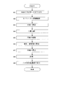
- 1 is a block diagram of a blood collection device and a measurement device of a blood collection measurement system according to an embodiment. It is the flowchart which showed the flow of the process regarding a series of quantitative analysis which concerns on an Example. It is the figure which represented the output of the detector signal typically. It is the figure which represented typically the mode of the plasma and blood cell which were plasma-separated.
- (A) is a schematic plan view of the groove
- (b) is a schematic sectional drawing of the groove
- FIG. 1 is a schematic perspective view of a blood collection device and a measurement device of the blood collection measurement system according to the embodiment
- FIG. 2 is a block diagram of the blood collection device and the measurement device of the blood collection measurement system according to the embodiment.
- blood will be described as an example of the liquid to be measured
- a blood collection measurement system will be described as an example of the liquid collection measurement system
- a blood collection device will be described as an example of the liquid collection device.
- the blood collection measurement system includes a blood collection device 10 that collects blood to be measured in time series, and radiation (for example, ⁇ ) contained in the collected blood. And a measuring device 40 that measures a line, a ⁇ -ray, and the like).
- blood after administration of a radiopharmaceutical into the body of a mouse is collected (ie, blood is collected), and the radiation contained in the blood is measured.
- plasma separation is performed, and radiation contained in the plasma and blood cells separated from each other is measured.
- Blood collection apparatus 10 corresponds to the liquid collection apparatus in the present invention
- measurement apparatus 40 corresponds to the measurement apparatus in the present invention.
- Blood collection apparatus 10 includes a microchip configured by stacking two glass substrates 11 and 12 vertically.
- the upper glass substrate 11 is subjected to a T-shaped groove process with a predetermined dimension, and the main flow path 13 and the side path 14 are formed by the groove formed by the groove process. Then, the upper glass substrate 11 and the glass substrate 12 are bonded to each other with the surface on which the groove is formed being inward. That is, the main flow path 13 and the side path 14 refer to a pipe portion formed of the glass substrate 12 and a groove formed with a predetermined dimension on the planar glass substrate 11.
- the glass substrate 11 corresponds to the substrate in the present invention
- the main flow path 13 corresponds to the flow path in the present invention.
- the material of the blood collection device 10 is not limited to glass, but may be any material that is optically transparent, such as acrylic, polycarbonate, COP (cycloolefin polymer).
- the upper glass substrate 11 and the glass substrate 12 may be bonded to each other with the groove-formed surface outside.
- a catheter 15 is disposed on the blood inlet side of the main flow path 13, and the main flow path 13 and the catheter 15 are connected via a connector 16.
- a microchip made of glass substrates 11 and 12 is installed in the immediate vicinity of the mouse, and a catheter 15 used for blood introduction is connected by the connector 16 described above, thereby preventing unnecessary blood from flowing out. In this way, blood is continuously fed into the main channel 13 via the catheter 15.
- a blood pipe 17 is disposed on the blood outlet side of the main flow path 13, and the main flow path 13 and the blood pipe 17 are connected via a connector 18.
- a bubble pipe 19 is disposed on the inlet side of the side path 14, and the side path 14 and the bubble pipe 19 are connected via a connector 20.
- the outlet side of the side path 14 is connected to the main channel 13 so as to be able to circulate, and bubbles are sent into the main channel 13 through the side path 14.
- a light source 21 and a photodiode 22 are disposed across the main flow path 13.
- the blood flowing through the main flow path 13 is irradiated with light from the light source 21, and the photodiode 22 detects light blocking by the blood, thereby measuring blood length information to be described later while optically monitoring (monitoring) the blood.
- the light source 21 and the photodiode 22 correspond to the optical measuring means in this invention.
- a dispenser 23 is connected to the downstream side of the blood pipe 17 described above.
- a disc (also referred to as “CD well”) 24 for receiving and storing blood dropped from the dispenser 23 is provided.
- a plurality of openings 25 for receiving the dropped blood are arranged radially on the center side of the disc 24.
- the circular plate 24 is grooved, and a plurality of U-shaped grooves 26 are formed radially by the grooves.
- Each U-shaped groove 26 is connected to the outer end of the above-described opening 25 on a one-to-one basis, and each U-shaped groove 26 is formed to extend in the radial direction of the disk 24. Yes.
- the disc 24 is formed so that blood can flow through the main flow path 13.
- the disc 24 corresponds to the flat plate in this invention.
- the measuring device 40 includes a reading unit 41.
- the reader 41 is provided with a cover for inserting the exposed imaging plate IP, and detects ⁇ + rays contained in the blood by reading the light excited from the imaging plate IP.
- the reading unit 41 includes a laser light source 42 and a photomultiplier tube (photomultiplier tube) 43, and a laser is applied from the laser light source 42 to the imaging plate IP.
- the photomultiplier tube 43 converts the light excited by the laser irradiation of the imaging plate IP into electrons and multiplies it, thereby detecting ⁇ + rays simultaneously two-dimensionally.
- the imaging plate IP and the reading unit 41 correspond to detection means in the present invention.
- the blood collection device 10 includes a pressure generator 30, a rotation drive unit 31, an imaging unit 32, an image processing unit 33, a groove, as shown in FIG. 2.
- a long / groove region calculation unit 34 and a volume calculation unit 35 are provided.
- the measuring device 40 includes an information calculating unit 44 in addition to the reading unit 41 described above.
- the blood collection device 10 and the measurement device 40 share a controller 50, an input unit 51, an output unit 52, and a memory unit 53.
- the pressure generator 30 corresponds to the taking-out means in the present invention
- the rotation driving unit 31 corresponds to the rotating means in the present invention
- the imaging unit 32 corresponds to the imaging means in the present invention
- the groove length / groove area calculation is performed.
- the unit 34 corresponds to the groove length / groove region calculating unit in the present invention
- the volume calculating unit 35 corresponds to the volume calculating unit in the present invention
- the information calculating unit 44 corresponds to the information calculating unit in the present invention.
- the pressure generator 30 operates the pressure of a gas (for example, air or argon), sends the gas to the main flow path 13 through the side path 14, and inserts the gas as a bubble at a specified predetermined interval. Then, the blood of the measurement object is separated and extracted in time series. That is, the bubbles serve as a separator in the present invention.
- a gas for example, air or argon
- the liquid to be measured is not limited to the gas, and the liquid to be measured is less likely to be mixed with the liquid to be measured (blood in this embodiment) or there is no possibility.
- a liquid other than that may be used as the separator.
- a liquid that does not mix with blood such as mineral oil or fluorine oil, may be used as the separator.
- the rotation drive unit 31 is configured by a motor, a turntable, etc., not shown, and rotates the turntable by rotating the motor to rotate the disk 24 placed on the turntable.
- the liquid to be measured (blood in this embodiment) is centrifuged using the centrifugal force of the disk 24 by the rotation drive unit 31.
- plasma separation is performed by centrifuging the blood to separate it into plasma and blood cells using the centrifugal force of the disc 24 by the rotation drive unit 31. become.
- the imaging unit 32 images the disk 24.
- a linear light source (not shown) having at least a length corresponding to the diameter of the disk 24 and a linear photodiode disposed opposite to the light source with the disk 24 interposed therebetween.
- a flat head scanner composed of an array (that is, a line sensor) (not shown) is employed.
- the disk 24 is imaged by scanning the disk 24 with a flat head scanner, and an image of the disk 24 is acquired.
- the image processing unit 33 performs various processes on the image of the disk 24 obtained by the imaging unit 32. For example, lag correction or dynamic range conversion may be performed.
- the groove length / groove region calculation unit 34 was centrifuged based on the difference in image density in the grooved U-shaped groove 26 (see FIG. 1) of the disk 24 imaged by the imaging unit 32. The groove length or groove area of each part of the liquid (blood in this embodiment) is obtained.
- the groove length / groove region calculation unit 34 obtains the groove length or groove region of each part of plasma and blood cells separated from plasma.
- the volume calculation unit 35 is based on the groove length of each part of the liquid (blood in this embodiment) obtained by the groove length / groove region calculation unit 34 and the cross-sectional area of the groove 26 (see FIG. 1), or the groove Based on the groove region of each part of the liquid (blood) and the depth of the groove 26 (see FIG. 1) obtained by the long / groove region calculation unit 34, the volume of each part is obtained.
- the groove length / groove region calculation unit 34 calculates the groove length of each part of plasma and blood cells and the cross-sectional area of the groove 26, or the groove Based on the groove region of each part of plasma and blood cells and the depth of the groove 26 obtained by the long / groove region calculation unit 34, the volume calculation unit 35 obtains the volume of each part.
- the information calculation unit 44 per unit volume based on the volume of the liquid (blood in this embodiment) obtained by the volume calculation unit 35 and the ⁇ + ray count information obtained by the imaging plate IP and the reading unit 41.
- the counting information of ⁇ + rays is obtained.
- the radiation count information is ⁇ + ray count (unit: [Bq])
- the radiation count information per unit volume is ⁇ + ray blood radioactivity concentration (unit: [Bq / ⁇ L]).
- the controller 50 comprehensively controls each part constituting the blood collection apparatus 10 and the measurement apparatus 40.
- the controller 50 includes a central processing unit (CPU).
- the input unit 51 inputs to the controller 50.
- the input unit 51 sends data and commands input by the operator to the controller 50.
- the input unit 51 includes a pointing device represented by a mouse, a keyboard, a joystick, a trackball, a touch panel, and the like.
- the output unit 52 outputs various data sent via the controller 50.
- the output unit 52 includes a display unit represented by a monitor, a printer, and the like.
- the memory unit 53 writes and stores various data sent via the controller 50.
- the memory unit 53 includes a storage medium represented by ROM (Read-only Memory), RAM (Random-Access Memory), and the like.
- ROM Read-only Memory
- RAM Random-Access Memory
- the groove region, the volume of each part obtained by the volume calculation unit 35, the blood radioactivity concentration obtained by the information calculation unit 44, and the like are written and stored in the RAM, and read from the RAM as necessary.
- the ROM stores a program for performing various quantitative analyzes in advance, and the controller 50 executes the program to perform quantitative analysis according to the program.
- the image processing unit 33, the groove length / groove region calculation unit 34, the volume calculation unit 35, and the information calculation unit 44 are, for example, a program stored in a ROM of a storage medium represented by the memory unit 53 described above or the input unit 51. This is realized by the controller 50 executing a command input by a pointing device represented by the above.
- FIG. 3 is a flowchart showing a flow of processing related to a series of quantitative analysis according to the embodiment
- FIG. 4 is a diagram schematically showing an output of a detector signal
- FIG. 5 is a diagram showing plasma separation.
- FIG. 6 is a diagram schematically showing the state of plasma and blood cells
- FIG. 6A is a schematic plan view of a disk groove
- FIG. 6B is a schematic cross-sectional view of a disk groove.
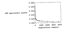
- FIG. 7 is a graph of blood radioactivity concentration.
- Step S1 Feeding blood into the main flow path A catheter 15 (see FIG. 1) is inserted into the mouse artery, and the arterial blood spontaneously released by the mouse blood pressure is passed through the catheter 15 through the main flow path 13 (FIG. 1 and FIG. 1). 2), blood is continuously fed into the main channel 13.
- an anticoagulant is introduced, or blood is fed after the anticoagulant is applied to the inner surface of the main channel 13 or the side channel 14 (see FIGS. 1 and 2) and coated.
- Step S2 Separation Control of Separator
- the separator is disposed opposite the light source 21 (see FIGS. 1 and 2) with the main flow path 13 in between. Since the light emitted from the light source 21 is incident on the photodiode 22 (see FIG. 1 and FIG. 2), the detector signal photoelectrically converted by the photodiode 22 becomes high level as shown in FIG. Output from the diode 22. Conversely, when blood is flowing through the main flow path 13, the light emitted from the light source 21 is blocked by the blood and blocked, so that no light enters the photodiode 22, as shown in FIG. The detector signal becomes a low level and is output from the photodiode 22.
- the photodiode 22 detects the light shielding by the blood, so that the blood length information is measured while optically monitoring the blood, and the separator ( That is, in this embodiment, the controller 50 (see FIG. 2) controls the volume of blood to be taken out by the pressure generator 30 (see FIG. 2) by controlling the interval between bubbles.
- the light source 21 and the photodiode 22 are linear optical systems (for example, the light source 21 is a linear light source disposed along the longitudinal direction of the main flow path 13 and a plurality of light sources.
- the light source 21 is a linear light source disposed along the longitudinal direction of the main flow path 13 and a plurality of light sources.
- each of the photodiodes 22 detects each distance (each of which is shown in FIG. 4).
- the output of the detector signal for the element number associated with the photodiode 22) is obtained.
- the interval between the detector signals that are at the low level is the length that the blood flows continuously, and the interval between the detector signals that are at the high level is the length of the separator between the blood and blood.
- the volume of blood to be taken out can be obtained from the blood interval (that is, the separator length). That is, the volume of blood to be taken out can be obtained by multiplying the blood interval by the cross-sectional area of the main flow path 13.
- the pressure adjustment to the pressure generator 30 or the side path 14 is performed in order to control the volume of blood to be taken out by the pressure generator 30 (see FIG. 2).
- the controller 30 controls the timing of feeding gas into the main flow path 13 (see FIGS. 1 and 2) via (see FIGS. 1 and 2). And thereby, the interval between the separators (bubbles) is controlled to control the volume of blood to be taken out.
- the interval between adjacent separators that is, the interval of blood to be taken out may be controlled.
- the separator interval may be controlled as described above.
- the blood space interval (length interval) or the separator space interval (length interval) is directly controlled.
- the volume of blood to be taken out may be controlled, and when the blood flow rate is high or when blood is taken out continuously as described above, as described above, the separator time interval (separator The volume of blood to be taken out may be controlled by controlling the cycle of the feeding timing.
- Step S3 Transfer to Disk A trace amount of blood taken out in step S2 is sent to the dispenser 23 (see FIGS. 1 and 2) via the blood pipe 17 (see FIGS. 1 and 2).
- the dispenser 23 drops each of the micro blood taken out into an opening 25 (see FIG. 1) of a disc (CD well) 24 (see FIGS. 1 and 2).
- the extracted trace blood is transferred to the disc 24.
- the number more than the blood collection frequency is prepared, and it uses.
- Step S4 Plasma Separation
- the controller 50 controls the rotation drive unit 31 (see FIG. 2).
- plasma separation is performed by rotating the disc 24 and separating it into plasma and blood cells.
- the outer end of the opening 25 (see FIG. 1) is opened and connected to the groove 26 (see FIG. 1) on a one-to-one basis, thereby smoothly separating blood during plasma separation.
- the groove 26 is U-shaped, the blood cells at the time of plasma separation are prevented from escaping out of the disk 24 by centrifugal force, and the bottom of the U-shape is separated after plasma separation as shown in FIG. Blood cell BH is allowed to settle.
- symbol BP of FIG. 5 shows plasma.
- Step S5 Imaging of disk
- the imaging part 32 (refer FIG. 2) images the plasma and blood cell by which plasma separation was carried out for every disk 24 (refer FIG. 1 and FIG. 2).
- the photodiode array of the flat head scanner acquires an optical image of the disk 24 separated into plasma and blood cells, and the optical image is obtained. Imaging is performed by obtaining an image of the disk 24.
- the image processing unit 33 (see FIG. 2) performs various processes on the image of the disk 24.
- the imaging unit 32 is not limited to an optical imaging unit, and for example, imaging may be performed by irradiating and detecting radiation.
- Step S6 Calculation of groove length and groove area
- a difference in absorbance appears on the image obtained by imaging plasma and blood cells. And can be easily identified.
- the groove length / groove region calculation unit 34 obtains the groove length or groove region of each part of plasma and blood cells. By converting the number of one-dimensional pixels having a difference in density into a groove length and converting the two-dimensional number of pixels into a groove region, the groove length or groove region of each part of plasma and blood cells is obtained.
- Step S7 Volume Calculation Based on the groove length of each part of plasma and blood cells and the cross-sectional area of the groove 26 (see FIG. 1) obtained by the groove length / groove region calculation unit 34 (see FIG. 2), Alternatively, the volume calculation unit 35 (see FIG. 2) obtains the volume of each part based on the groove region and the depth of the groove 26 of each part of plasma and blood cells obtained by the groove length / groove region calculation part 34.
- the length in the longitudinal direction of the groove 26 (including the opening 25), that is, the groove length is x, and is rectangular as shown in the sectional view of FIG.
- the depth of the groove 26 is d
- the length of the groove 26 in the short direction that is, the groove width is L, as shown in FIGS. 6 (a) and 6 (b).
- Step S8 Counting
- the disc 24 (see FIGS. 1 and 2) that has been plasma-separated into plasma and blood cells is stored as a sample by opening a cassette (not shown) on the imaging plate IP (see FIG. 1). (See) and close the cassette.
- the disk 24 is taken out from the cassette, and exposure is performed by irradiating the imaging plate IP with light. By this exposure, electrons are captured by lattice defects of the phosphor (not shown) of the imaging plate IP due to the ionizing ability of ⁇ + rays contained in the blood.
- the exposed imaging plate IP is taken out from the cassette and inserted into the cover portion of the reading unit 41 (see FIGS. 1 and 2) of the measuring device 40 (see FIGS. 1 and 2).
- the imaging plate IP (see FIG. 1) is irradiated with laser from the laser light source 42 (see FIGS. 1 and 2) of the reading unit 41 (see FIGS. 1 and 2).
- the trapped electrons are excited to the conductor by this irradiation and recombine with holes, and are excited as light from the phosphor.
- the photomultiplier tube 43 (see FIGS. 1 and 2) converts the light excited by the laser irradiation to the imaging plate IP into electrons and multiplies it, so that it is simultaneously detected as an electric pulse in two dimensions. And count. Note that after irradiating the imaging plate IP from the laser light source 42, the captured electrons are erased by irradiating the imaging plate IP with light from an erasing light source (not shown) for reuse.
- Step S9 Calculation of Radioactivity Concentration in Blood Plasma volume V p , blood cell volume V h obtained by volume calculation unit 35 (see FIG. 2), ⁇ obtained by imaging plate IP and reading unit 41 + based on the count information of the line (see FIG. 2) information calculating unit 44 blood radioactivity concentration which is count information on beta + lines per unit volume is obtained.
- FIG. 7 By rearranging the results of the blood radioactivity concentration by taking out time, a graph of the blood radioactivity concentration curve as shown in FIG. 7 is finally obtained.
- the horizontal axis in FIG. 7 is the extraction time, that is, the acquisition time (indicated as “Acquisition time” in FIG. 7), and the vertical axis in FIG. 7 is the blood radioactivity concentration (indicated as “PET equivalent counts” in FIG. 7).
- PET equivalent counts in FIG. 7
- the volume of the blood taken out depends on the cross-sectional area of the groove 26 (see FIGS. 1 and 2) of the disk 24 (see FIGS. 1 and 2) and the imaging unit 32 (see FIG. 2).
- the radiation counting accuracy (statistical accuracy) is determined by the exposure time to the imaging plate IP. In consideration of the attenuation of radiation and the required number of samplings, a plurality of disks 24 may be prepared and sequentially exposed with the imaging plate IP for imaging.
- the blood collection device 10 includes (a) a flow path (main flow path 13 in the present embodiment) and (b) a take-out means (pressure generator 30 in the present embodiment). Is provided in the middle of the path 13) at a specified predetermined interval, such as gas (air or argon in the present embodiment) or a liquid (measuring target) different from the above-described liquid to be measured (blood in this embodiment).
- a specified predetermined interval such as gas (air or argon in the present embodiment) or a liquid (measuring target) different from the above-described liquid to be measured (blood in this embodiment).
- the liquid is blood, mineral oil, fluorine-based oil, or the like
- the extraction means pressure generator 30
- the liquid (blood) described above is continuously fed into the flow path (main flow path 13) and inserted with the separator made of gas or liquid, so that the liquid (blood) with a minute volume of, for example, about 1 [ ⁇ L] is obtained. Can be taken out.
- the consumption of the liquid (blood) to be measured associated with the conventional cleaning liquid for each collection is suppressed, and the amount of collected liquid (blood collection in this embodiment) is minimized. Can be suppressed.
- the work of inserting the separator is excellent in high speed, it is possible to ensure the frequent collection of a short time, that is, frequent collection (blood collection in this embodiment). As a result, the collection amount (blood collection amount) of the liquid can be reduced to ensure the frequency of collection (blood collection).
- the main flow path 13 is preferably formed by grooving a flat glass substrate 11 with a predetermined dimension. That is, since the groove is processed with a predetermined dimension, if the groove length or the groove region of the liquid (blood in this embodiment) fed into the main channel 13 is known, the groove cut with the predetermined dimension is cut.
- the volume of the liquid (blood) sent into the main flow path 13 can be defined based on the area or the depth of the groove.
- the blood collection apparatus 10 preferably includes (c) optical measurement means (in this embodiment, the light source 21 and the photodiode 22).
- the optical measuring means (the light source 21 and the photodiode 22) described above optically monitors the liquid to be measured (blood in this embodiment) flowing through the flow path (main flow path 13 in this embodiment).
- the above-mentioned extraction means (in this embodiment, pressure generation)
- the volume of the liquid (blood) to be removed is controlled by the vessel 30).
- the flow rate of the liquid (blood), and hence the volume of the liquid (blood) can be controlled by the interval between the separators, and the amount of collected liquid (the amount of blood collected in this embodiment) can be minimized.
- a flat plate (disk 24 in this embodiment) and (e) a rotating means (rotation drive unit 31 in this embodiment) are provided, and the flat plate (disk 24) has a flow path (this embodiment). Then, a plurality of grooves formed in the radial direction are formed so that the liquid to be measured can flow through the main flow path 13) (in this embodiment, the liquid can be distributed by interposing the dispenser 23).
- the rotation means (rotation drive unit 31) rotates the flat plate (disk 24).
- the liquid can be centrifuged using the centrifugal force of the flat plate (disk 24) by the rotating means (rotation drive unit 31).
- the liquid is blood as in this embodiment, the blood is centrifuged to separate it into plasma and blood cells using the centrifugal force of the flat plate (disk 24) by the rotating means (rotation drive unit 31). It is possible to perform plasma separation.
- each part of the centrifuged liquid (plasma and blood cells when the liquid is blood as in this embodiment) is present separately.
- the flat plate (the disk 24 in this embodiment) is imaged.
- the volume of each part is obtained more accurately using the imaging result.
- imaging means imaging unit 32 in this embodiment
- groove length / groove area calculation means groove length / groove area calculation 34 in this embodiment
- volume calculation means volume calculation means.
- the liquid is blood as in the present embodiment
- plasma and blood cells appear as light and shade differences due to differences in absorbance or radioactivity concentration, and can be easily identified on the image.
- Centrifugation is performed based on the difference in image density (that is, the difference in absorbance or radioactivity concentration) in the grooved groove 26 of the flat plate (the disk 24 in this embodiment) imaged by the imaging means (imaging unit 32).
- the groove length / groove area calculating means (groove length / groove area calculating section 34) obtains the groove length or groove area of each part of the liquid (each part of plasma and blood cells in this embodiment).
- the volume calculating means (volume calculating part 35). Finds the volume of each part (plasma and blood cell parts) described above.
- the groove length or groove area of each part of liquid is obtained by the groove length / groove area calculating means (groove length / groove area calculating unit 34), the cross-sectional area of the groove 26 or the groove 26 Based on the depth, the volume of each part (plasma and each part of blood cells) can be determined.
- the liquid (blood in this embodiment) defined by the flow path (main flow path 13 in this embodiment) upstream from the flat plate (disk 24 in this embodiment) is transferred to the flat plate (disk 24).
- the image information (image of the image) of the flat plate (disk 24) imaged by the imaging means (imaging unit 32 in this embodiment) is considered. Since the volume of each part (each part of plasma and blood cells in the present embodiment) of the liquid contained in the flat plate (disk 24) is obtained anew using the density difference), each part (each part of plasma and blood cells) is determined. The volume can be determined even more accurately.
- the liquid collection device is a device for collecting blood, that is, the blood collection device 10.
- a detecting unit imaging plate IP and reading unit 41 in the present embodiment
- an information calculating unit information calculating unit 44 in the present embodiment
- the volume of the liquid (blood) obtained based on the information of the grooved groove 26 and the two-dimensional image information (in this embodiment) of light or radiation obtained by the detection means (imaging plate IP and reading unit 41).
- the information calculation means obtains information on light or radiation per unit volume (in the present embodiment, blood radioactivity concentration) based on the radiation count information). That is, the liquid (blood) that has already been transferred to the flat plate (disk 24) is obtained based on the image information on the flat plate (disk 24) and the information on the grooved grooves 26 on the flat plate (disk 24). The volume of the liquid (blood) does not increase or decrease thereafter, and information on light or radiation per unit volume (blood radioactivity concentration) is obtained based on the volume of the liquid (blood). Therefore, by using the image information of the flat plate (disk 24), the volume of liquid (blood) is not increased or decreased, and the information on light or radiation per unit volume (blood radioactivity concentration) can be accurately obtained. Further, the detection means (imaging plate IP and reading unit 41) can detect the two-dimensional simultaneous detection, thereby reducing the influence of light fading and radiation attenuation.
- the radiation counting information per unit volume (in the present embodiment, blood radioactivity concentration) is information.
- the calculation means in this embodiment, the information calculation unit 35) can be obtained accurately.
- the imaging plate IP and the reading unit 41 receive the radiation contained in the plasma and blood cells obtained by centrifuging the blood and separating the plasma into two-dimensional radiation information. And counting each part based on the volume of each part of the plasma and blood cells and the counting information of the radiation of each part obtained by the imaging plate IP and the reading part 41, respectively.
- Information (in this embodiment, the blood radioactivity concentration) is obtained by the information calculating means (in this embodiment, the information calculating section 35).
- the volume of each part of all plasma and blood cells on the disc 24 is obtained in parallel, and the count information (blood radioactivity concentration in this embodiment) per unit volume is obtained in parallel (that is, obtained simultaneously). It is possible.
- the detection time (measurement time) by the imaging plate IP can be extended, and there is also an effect that a low-concentration radiation dose can be measured with high statistical accuracy.
- the volume of the liquid (blood) obtained on the basis of the image information of the flat plate (disk 24 in this embodiment) and the information of the grooved groove 26 of the flat plate (disk 24) is There is no increase or decrease thereafter, and light or radiation information (in this embodiment, blood radioactivity concentration) per unit volume is obtained based on the volume of the liquid (blood). Therefore, by using the image information of the flat plate (disk 24), the volume of liquid (blood) is not increased or decreased, and the information on light or radiation per unit volume (blood radioactivity concentration) can be accurately obtained.
- the blood collection measurement system includes (a) a flow path (main flow path 13 in the present embodiment), (b) extraction means (pressure generator 30 in the present embodiment), It has. That is, at a specified predetermined interval, a gas (air or argon in this embodiment) or a liquid other than the liquid to be measured (blood in this embodiment) described above (if the liquid to be measured is blood) By inserting mineral oil, fluorine-based oil, or the like) as a separator, the extraction means (pressure generator 30) separates and extracts the liquid (blood) to be measured in time series.
- Each liquid (blood) taken out by the take-out means (pressure generator 30) is contained in the light (luminescence) contained in the liquid (blood) or the light generated from the fluorescent substance or in the liquid (blood) to be measured.
- the measuring device 40 provided in the system measures the radiation (in this embodiment, only radiation) that is present. In this way, as described in the blood collection device 10 according to the present embodiment, the measurement amount 40 according to the present embodiment is ensured by reducing the amount of collected liquid (blood collection amount) to ensure the frequency of collection (blood collection). As described above, information on light or radiation per unit volume (in this embodiment, blood radioactivity concentration) can be accurately obtained.
- the main flow path 13 described above is preferably formed by grooving a flat glass substrate 11 with a predetermined dimension.
- optical measurement means in this embodiment, the light source 21 and the photodiode 22
- the flat plate (disk 24) contains the liquid (blood) to be measured, and is the same as the flat plate having a predetermined dimension and a plurality of grooves, and the flow path (main flow path 13) is the same.
- the liquid (blood) to be measured is formed so as to be able to flow, and a plurality of grooves formed in the radial direction are provided.
- imaging means imaging section 32 in this embodiment
- groove length / groove area calculating means In the present embodiment, groove length / groove region calculation 34
- volume calculation means volume calculation unit 35 in the present embodiment
- the contrast of the image described in the blood collection device 10 corresponds to image information of a flat plate (in the present embodiment, the disk 24) in the blood collection measurement system
- the cross-sectional area or groove of the groove 26 described in the blood collection device 10 is the same.
- the depth corresponds to the groove information in the blood collection measurement system.
- the imaging plate IP and the reading unit 41 detects and counts.
- the liquid to be measured is blood
- the imaging plate IP and the reading unit 41 separately count the detected radiation, and count the volume of each part of plasma and blood cells, and the radiation count information of each part obtained by the imaging plate IP and the reading unit 41, respectively.
- the information calculation means obtains the count information (blood radioactivity concentration in this embodiment) of each unit per unit volume.
- the present invention is not limited to the above embodiment, and can be modified as follows.
- the liquid collection measuring system (the blood collection measuring system in the embodiment) includes the liquid collection device (the blood collection device 10 in the embodiment) and the measurement device (the measurement device 40 in the embodiment).
- the liquid collecting device alone or the measuring device alone may be used.
- the liquid is not limited to blood as long as it is a liquid to be measured.
- it may be a liquid containing a fluorescent agent or a mixed liquid used in an analyzer.
- the liquid collection device includes (c) optical measurement means (the light source 21 and the photodiode 22 in the embodiment).
- optical measurement means the light source 21 and the photodiode 22 in the embodiment.
- the light source 21 and the photodiode 22 have been described as an example of the optical measurement means.
- any means for measuring the liquid interval while optically monitoring the liquid to be measured can be used for the light source 21 and the photodiode 22.
- the light source 21 and the photodiode 22 are so-called “transmission type sensors” that are arranged to face each other with the main flow channel 13 interposed therebetween as shown in FIG.
- a so-called “reflective sensor” may be used in which light detection means typified by a photodiode is provided on the same side, and detection is performed using reflected light from blood.
- the centrifugal separation in order to apply the centrifugal separation of the liquid (blood in the embodiment) in the liquid collection device (blood collection device 10 in the embodiment), (d) a flat plate (disk 24 in the embodiment) And (e) the rotation means (rotation drive unit 31).
- the centrifugal separation when the centrifugal separation is not performed, it is not always necessary to provide the flat plate and the rotation means.
- the dispenser 23 shown in FIG. the flat plate is not limited to the circular plate 24 but may be a square plate, a polygonal plate, or the like, but it is preferable that the center of rotation has a center of gravity considering rotation.
- the liquid to be measured is formed to flow through the flow path (in the embodiment, the main flow path 13) for the flat plate (disk 24).
- the substrate (the glass substrate 11 in the embodiment) is configured to be detachable, and the flat plate (disk 24) is configured so that the flow channel (main flow channel 13) and the flat groove 26 are fitted when attached. May be formed so that the liquid to be measured can flow through the flow path (main flow path 13 in the embodiment).
- the imaging unit may be a radiation imaging unit including a radiation irradiation unit and a radiation detection unit.
- the radioactivity concentration is different in each part of the centrifuged liquid, and the different points are used.
- the liquid is blood, it appears as a difference in density on the image of plasma and blood cells due to the difference in radioactivity concentration, and can be easily identified on the image.
- a liquid containing a fluorescent agent may be used as described in the modification (2).
- a fluorescent substance that is a fluorescent agent is included in the liquid, and the measuring device measures light generated from the fluorescent substance with a CCD camera or the like. Therefore, the information of light per unit volume is accurately obtained.
- a two-dimensional radiation sensor such as a scintillator array and a photomultiplier or a semiconductor detector
- the light generated from the luminescent material may be measured in the same manner.
- the liquid collection measurement system in the embodiment described above, (a) the flow path (main flow path 13 in the embodiment) and (b) the extraction means (pressure generator 30) are provided.
- the configuration of the liquid collection device (blood collection device 10 in the embodiment) provided in the system is not particularly limited as long as the liquid to be measured is collected, and the flow collection device and the extraction unit are necessarily provided. There is no need. You may perform a quantitative analysis using the liquid extract
Abstract
Priority Applications (5)
| Application Number | Priority Date | Filing Date | Title |
|---|---|---|---|
| CN200880125368.3A CN101925821B (zh) | 2008-01-22 | 2008-01-22 | 测定装置及具有其的液体提取测定系统 |
| EP08703647.1A EP2239585B1 (fr) | 2008-01-22 | 2008-01-22 | Système de prélèvement et de mesure de liquide |
| PCT/JP2008/050803 WO2009093306A1 (fr) | 2008-01-22 | 2008-01-22 | Dispositif de prélèvement de liquide, dispositif de mesure et système de prélèvement/mesure de liquide équipé de ceux-ci |
| US12/863,968 US8358405B2 (en) | 2008-01-22 | 2008-01-22 | Measuring apparatus, and liquid collecting and measuring system having the same |
| JP2009550391A JP5066583B2 (ja) | 2008-01-22 | 2008-01-22 | 測定装置並びにそれらを備えた液体採取測定システム |
Applications Claiming Priority (1)
| Application Number | Priority Date | Filing Date | Title |
|---|---|---|---|
| PCT/JP2008/050803 WO2009093306A1 (fr) | 2008-01-22 | 2008-01-22 | Dispositif de prélèvement de liquide, dispositif de mesure et système de prélèvement/mesure de liquide équipé de ceux-ci |
Publications (1)
| Publication Number | Publication Date |
|---|---|
| WO2009093306A1 true WO2009093306A1 (fr) | 2009-07-30 |
Family
ID=40900824
Family Applications (1)
| Application Number | Title | Priority Date | Filing Date |
|---|---|---|---|
| PCT/JP2008/050803 WO2009093306A1 (fr) | 2008-01-22 | 2008-01-22 | Dispositif de prélèvement de liquide, dispositif de mesure et système de prélèvement/mesure de liquide équipé de ceux-ci |
Country Status (5)
| Country | Link |
|---|---|
| US (1) | US8358405B2 (fr) |
| EP (1) | EP2239585B1 (fr) |
| JP (1) | JP5066583B2 (fr) |
| CN (1) | CN101925821B (fr) |
| WO (1) | WO2009093306A1 (fr) |
Cited By (13)
| Publication number | Priority date | Publication date | Assignee | Title |
|---|---|---|---|---|
| JP2011075420A (ja) * | 2009-09-30 | 2011-04-14 | Shimadzu Corp | 遠心分離装置 |
| WO2011117952A1 (fr) * | 2010-03-24 | 2011-09-29 | 株式会社島津製作所 | Système de mesure |
| WO2011117953A1 (fr) * | 2010-03-24 | 2011-09-29 | 株式会社島津製作所 | Système de mesure |
| WO2013031240A1 (fr) * | 2011-08-31 | 2013-03-07 | 株式会社島津製作所 | Dispositif support pour l'instillation d'un liquide |
| JP2013061275A (ja) * | 2011-09-14 | 2013-04-04 | Shimadzu Corp | 測定システムに用いられる表示装置 |
| WO2013057762A1 (fr) | 2011-10-19 | 2013-04-25 | 株式会社島津製作所 | Dispositif d'affichage, procédé d'affichage et programme d'affichage, utilisés dans un système de mesure |
| JP2013101029A (ja) * | 2011-11-08 | 2013-05-23 | Shimadzu Corp | 測定システムに用いられる表示装置、表示方法並びに表示プログラム |
| WO2014021060A1 (fr) * | 2012-08-03 | 2014-02-06 | 株式会社 日立ハイテクノロジーズ | Système d'analyse et procédé d'analyse |
| WO2014033797A1 (fr) * | 2012-09-03 | 2014-03-06 | 株式会社島津製作所 | Procédé d'instillation de liquide |
| JP2014530358A (ja) * | 2011-09-25 | 2014-11-17 | セラノス, インコーポレイテッド | 多重分析のためのシステム及び方法 |
| JP2015232581A (ja) * | 2009-12-30 | 2015-12-24 | ライフスキャン・インコーポレイテッドLifescan,Inc. | 充填時間を使用してバイオセンサーの精度を改善するためのシステム、装置及び方法 |
| US9726658B2 (en) | 2014-04-25 | 2017-08-08 | Shimadzu Corporation | Display device, display method, and display program used in measurement system |
| JP2018049026A (ja) * | 2014-10-14 | 2018-03-29 | ベクトン・ディキンソン・アンド・カンパニーBecton, Dickinson And Company | オープンセル発泡体を用いた血液サンプルの管理 |
Families Citing this family (11)
| Publication number | Priority date | Publication date | Assignee | Title |
|---|---|---|---|---|
| CN103323610B (zh) | 2007-10-02 | 2016-12-28 | 赛拉诺斯股份有限公司 | 模块化现场护理装置及其应用 |
| TWI639703B (zh) | 2011-01-21 | 2018-11-01 | 賽瑞諾斯有限公司 | 樣本使用最大化之系統及方法 |
| US8475739B2 (en) | 2011-09-25 | 2013-07-02 | Theranos, Inc. | Systems and methods for fluid handling |
| US9664702B2 (en) | 2011-09-25 | 2017-05-30 | Theranos, Inc. | Fluid handling apparatus and configurations |
| US9632102B2 (en) | 2011-09-25 | 2017-04-25 | Theranos, Inc. | Systems and methods for multi-purpose analysis |
| US20140170735A1 (en) | 2011-09-25 | 2014-06-19 | Elizabeth A. Holmes | Systems and methods for multi-analysis |
| US9810704B2 (en) | 2013-02-18 | 2017-11-07 | Theranos, Inc. | Systems and methods for multi-analysis |
| US10012664B2 (en) | 2011-09-25 | 2018-07-03 | Theranos Ip Company, Llc | Systems and methods for fluid and component handling |
| US9460562B2 (en) | 2015-01-09 | 2016-10-04 | International Business Machines Corporation | Providing volume indicators based on received images of containers |
| JP7024461B2 (ja) * | 2018-02-01 | 2022-02-24 | 株式会社島津製作所 | マイクロ流路内に保持された検体の前処理方法、その前処理方法を実行するための前処理装置及びその前処理装置を備えた分析システム |
| JP6954473B2 (ja) * | 2018-07-23 | 2021-10-27 | 株式会社島津製作所 | マイクロ流体デバイス観察装置 |
Citations (3)
| Publication number | Priority date | Publication date | Assignee | Title |
|---|---|---|---|---|
| JPS56147013A (en) * | 1980-04-17 | 1981-11-14 | Kyoto Denshi Kogyo Kk | Detecting method for flow rate of liquid |
| JPH01307608A (ja) * | 1988-06-06 | 1989-12-12 | Hitachi Ltd | 流体量計測装置 |
| JP2004109082A (ja) * | 2002-09-20 | 2004-04-08 | Japan Science & Technology Corp | 血液分析装置及び血漿分離方法 |
Family Cites Families (8)
| Publication number | Priority date | Publication date | Assignee | Title |
|---|---|---|---|---|
| US3679367A (en) * | 1970-09-14 | 1972-07-25 | Technicon Instr | Apparatus for determining the pack volume of particulates in liquid mixtures |
| DE19542225B4 (de) * | 1995-11-01 | 2011-05-26 | L.U.M. Gmbh | Verfahren und Vorrichtung zur Bestimmung von rheologischen und mechanischen Stoffkenngrößen |
| US6388740B1 (en) * | 1999-06-22 | 2002-05-14 | Robert A. Levine | Method and apparatus for timing intermittent illumination of a sample tube positioned on a centrifuge platen and for calibrating a sample tube imaging system |
| JP2004294366A (ja) * | 2003-03-28 | 2004-10-21 | Seitai Kagaku Kenkyusho:Kk | ラジオ液体クロマトグラフ |
| KR100552706B1 (ko) * | 2004-03-12 | 2006-02-20 | 삼성전자주식회사 | 핵산 증폭 방법 및 장치 |
| JP4170947B2 (ja) * | 2004-04-09 | 2008-10-22 | 株式会社日立ハイテクノロジーズ | 生体試料成分検出法及びその装置 |
| WO2006005371A1 (fr) * | 2004-07-13 | 2006-01-19 | Commissariat A L'energie Atomique | Dispositif microfluidique destine a effectuer une pluralite de reactions et ses utilisations |
| EP1865305A1 (fr) * | 2005-03-31 | 2007-12-12 | Kabushiki Kaisha Toshiba | Dispositif de mesure de fluorescence, procédé de mesure de fluorescence, récipient pour mesure de fluorescence, et procédé de fabrication du récipient pour mesure de fluorescence |
-
2008
- 2008-01-22 JP JP2009550391A patent/JP5066583B2/ja not_active Expired - Fee Related
- 2008-01-22 CN CN200880125368.3A patent/CN101925821B/zh not_active Expired - Fee Related
- 2008-01-22 WO PCT/JP2008/050803 patent/WO2009093306A1/fr active Application Filing
- 2008-01-22 US US12/863,968 patent/US8358405B2/en not_active Expired - Fee Related
- 2008-01-22 EP EP08703647.1A patent/EP2239585B1/fr not_active Not-in-force
Patent Citations (3)
| Publication number | Priority date | Publication date | Assignee | Title |
|---|---|---|---|---|
| JPS56147013A (en) * | 1980-04-17 | 1981-11-14 | Kyoto Denshi Kogyo Kk | Detecting method for flow rate of liquid |
| JPH01307608A (ja) * | 1988-06-06 | 1989-12-12 | Hitachi Ltd | 流体量計測装置 |
| JP2004109082A (ja) * | 2002-09-20 | 2004-04-08 | Japan Science & Technology Corp | 血液分析装置及び血漿分離方法 |
Non-Patent Citations (3)
| Title |
|---|
| H. _M. WU; G. SUI; C. _C. LEE; M. L. PRINS; W. LADNO; H. _D. LIN; A. S. YU; M. E. PHELPS; S. _C: HUANG: "ln vivo quantitation of glucose metabolism in mice using small-animal PET and a microfluidic device", J NUCF MED, vol. 48, 2007, pages 837 - 845, XP055063843, DOI: doi:10.2967/jnumed.106.038182 |
| L. CONVERT; G. M. BRASSARD; J. CADORETTE; D. ROULEAU; E. CROTEAU; M. ARCHAMBAULT; R. FONTAINE; R. LECOMTE: "A microvolumetric ? blood counter for pharmacokinetic PET studies in small animals", IEEE NUCLEAR SCI, vol. 54, no. 1, 2007 |
| See also references of EP2239585A4 * |
Cited By (22)
| Publication number | Priority date | Publication date | Assignee | Title |
|---|---|---|---|---|
| JP2011075420A (ja) * | 2009-09-30 | 2011-04-14 | Shimadzu Corp | 遠心分離装置 |
| JP2015232581A (ja) * | 2009-12-30 | 2015-12-24 | ライフスキャン・インコーポレイテッドLifescan,Inc. | 充填時間を使用してバイオセンサーの精度を改善するためのシステム、装置及び方法 |
| JP5298237B2 (ja) * | 2010-03-24 | 2013-09-25 | 株式会社島津製作所 | 測定システム |
| WO2011117952A1 (fr) * | 2010-03-24 | 2011-09-29 | 株式会社島津製作所 | Système de mesure |
| WO2011117953A1 (fr) * | 2010-03-24 | 2011-09-29 | 株式会社島津製作所 | Système de mesure |
| EP2551664A1 (fr) * | 2010-03-24 | 2013-01-30 | Shimadzu Corporation | Système de mesure |
| US9498154B2 (en) | 2010-03-24 | 2016-11-22 | Shimadzu Corporation | Measuring system capable of separating liquid and determining boundary of separated liquid |
| EP2551664A4 (fr) * | 2010-03-24 | 2013-07-10 | Shimadzu Corp | Système de mesure |
| WO2013031240A1 (fr) * | 2011-08-31 | 2013-03-07 | 株式会社島津製作所 | Dispositif support pour l'instillation d'un liquide |
| JP2013061275A (ja) * | 2011-09-14 | 2013-04-04 | Shimadzu Corp | 測定システムに用いられる表示装置 |
| JP2014530358A (ja) * | 2011-09-25 | 2014-11-17 | セラノス, インコーポレイテッド | 多重分析のためのシステム及び方法 |
| US20140253594A1 (en) * | 2011-10-19 | 2014-09-11 | Shimadzu Corporation | Display apparatus, a display method and a display program for use in a measuring system |
| JPWO2013057762A1 (ja) * | 2011-10-19 | 2015-04-02 | 株式会社島津製作所 | 測定システムに用いられる表示装置、表示方法並びに表示プログラム |
| WO2013057762A1 (fr) | 2011-10-19 | 2013-04-25 | 株式会社島津製作所 | Dispositif d'affichage, procédé d'affichage et programme d'affichage, utilisés dans un système de mesure |
| JP2013101029A (ja) * | 2011-11-08 | 2013-05-23 | Shimadzu Corp | 測定システムに用いられる表示装置、表示方法並びに表示プログラム |
| WO2014021060A1 (fr) * | 2012-08-03 | 2014-02-06 | 株式会社 日立ハイテクノロジーズ | Système d'analyse et procédé d'analyse |
| WO2014033797A1 (fr) * | 2012-09-03 | 2014-03-06 | 株式会社島津製作所 | Procédé d'instillation de liquide |
| US9726658B2 (en) | 2014-04-25 | 2017-08-08 | Shimadzu Corporation | Display device, display method, and display program used in measurement system |
| JP2018049026A (ja) * | 2014-10-14 | 2018-03-29 | ベクトン・ディキンソン・アンド・カンパニーBecton, Dickinson And Company | オープンセル発泡体を用いた血液サンプルの管理 |
| JP2021051083A (ja) * | 2014-10-14 | 2021-04-01 | ベクトン・ディキンソン・アンド・カンパニーBecton, Dickinson And Company | オープンセル発泡体を用いた血液サンプルの管理 |
| US11298061B2 (en) | 2014-10-14 | 2022-04-12 | Becton, Dickinson And Company | Blood sample management using open cell foam |
| JP7203806B2 (ja) | 2014-10-14 | 2023-01-13 | ベクトン・ディキンソン・アンド・カンパニー | オープンセル発泡体を用いた血液サンプルの管理 |
Also Published As
| Publication number | Publication date |
|---|---|
| US20100294950A1 (en) | 2010-11-25 |
| EP2239585A4 (fr) | 2013-07-10 |
| CN101925821A (zh) | 2010-12-22 |
| CN101925821B (zh) | 2014-09-24 |
| JP5066583B2 (ja) | 2012-11-07 |
| EP2239585A1 (fr) | 2010-10-13 |
| JPWO2009093306A1 (ja) | 2011-05-26 |
| EP2239585B1 (fr) | 2016-11-30 |
| US8358405B2 (en) | 2013-01-22 |
Similar Documents
| Publication | Publication Date | Title |
|---|---|---|
| JP5066583B2 (ja) | 測定装置並びにそれらを備えた液体採取測定システム | |
| JP5564489B2 (ja) | 液体採取システムおよびその方法 | |
| JP5442849B2 (ja) | 測定システム | |
| US5827746A (en) | Method to determine the sedimentation of blood and relative device | |
| WO2009094761A1 (fr) | Appareil et procédé d'analyse d'urine | |
| KR20210138640A (ko) | 현장 진단 농도 분석기 | |
| JP5298237B2 (ja) | 測定システム | |
| JP2011075420A (ja) | 遠心分離装置 | |
| JP5776782B2 (ja) | 測定システムに用いられる表示装置、表示方法並びに表示プログラム | |
| KR20220018000A (ko) | 라인 부피 캘리브레이션 시스템 및 방법 | |
| JP6098315B2 (ja) | 光または放射線測定用容器並びに測定システム | |
| JP6218352B2 (ja) | 測定システムに用いられる表示装置、表示方法並びに表示プログラム | |
| JP5899829B2 (ja) | 測定システムに用いられる表示装置、表示方法並びに表示プログラム | |
| JP5724780B2 (ja) | 測定システムに用いられる表示装置 | |
| JP2014211308A (ja) | 液体滴下補助装置 | |
| JP2015152471A (ja) | 液体採取装置 | |
| KR20220116300A (ko) | 부유체를 갖는 액체의 분석을 위한 완벽한 방법 |
Legal Events
| Date | Code | Title | Description |
|---|---|---|---|
| WWE | Wipo information: entry into national phase |
Ref document number: 200880125368.3 Country of ref document: CN |
|
| 121 | Ep: the epo has been informed by wipo that ep was designated in this application |
Ref document number: 08703647 Country of ref document: EP Kind code of ref document: A1 |
|
| ENP | Entry into the national phase |
Ref document number: 2009550391 Country of ref document: JP Kind code of ref document: A |
|
| WWE | Wipo information: entry into national phase |
Ref document number: 12863968 Country of ref document: US |
|
| NENP | Non-entry into the national phase |
Ref country code: DE |
|
| REEP | Request for entry into the european phase |
Ref document number: 2008703647 Country of ref document: EP |
|
| WWE | Wipo information: entry into national phase |
Ref document number: 2008703647 Country of ref document: EP |