WO2009084542A1 - 髄内釘及びそれに用いられる制御部材 - Google Patents
髄内釘及びそれに用いられる制御部材 Download PDFInfo
- Publication number
- WO2009084542A1 WO2009084542A1 PCT/JP2008/073450 JP2008073450W WO2009084542A1 WO 2009084542 A1 WO2009084542 A1 WO 2009084542A1 JP 2008073450 W JP2008073450 W JP 2008073450W WO 2009084542 A1 WO2009084542 A1 WO 2009084542A1
- Authority
- WO
- WIPO (PCT)
- Prior art keywords
- control member
- holes
- intramedullary nail
- main body
- lag screw
- Prior art date
Links
Images


Classifications
-
- A—HUMAN NECESSITIES
- A61—MEDICAL OR VETERINARY SCIENCE; HYGIENE
- A61B—DIAGNOSIS; SURGERY; IDENTIFICATION
- A61B17/00—Surgical instruments, devices or methods, e.g. tourniquets
- A61B17/56—Surgical instruments or methods for treatment of bones or joints; Devices specially adapted therefor
- A61B17/58—Surgical instruments or methods for treatment of bones or joints; Devices specially adapted therefor for osteosynthesis, e.g. bone plates, screws, setting implements or the like
- A61B17/68—Internal fixation devices, including fasteners and spinal fixators, even if a part thereof projects from the skin
- A61B17/74—Devices for the head or neck or trochanter of the femur
- A61B17/742—Devices for the head or neck or trochanter of the femur having one or more longitudinal elements oriented along or parallel to the axis of the neck
- A61B17/744—Devices for the head or neck or trochanter of the femur having one or more longitudinal elements oriented along or parallel to the axis of the neck the longitudinal elements coupled to an intramedullary nail
Definitions
- the present invention relates to an intramedullary nail and a control member used therefor, and in particular, a rod-like main body having a plurality of through holes introduced into the intramedullary bone from one end of an elongated bone and intersecting with the axis thereof
- the present invention relates to an intramedullary nail or the like provided with a plurality of engaging members which are inserted into corresponding through holes of the main body and engageable with bones.
- Intramedullary nails are used for treatment of femoral fractures and the like. The following techniques are available for intramedullary nails.
- the intramedullary nail is inserted into the main body (intramedullar rod in Patent Document 1) inserted into the intramedullary bone from one end of the elongated bone in the thigh, and the inclined opening formed in the main body. It comprises an engaging member (neck screw in Patent Document 1 etc.) engaged with a bone, and an adjusting member (bore etc. in Patent Document 1 etc.) capable of determining the degree of fixation of the engaging member to the main body.
- the engaging member is formed with a groove along the extending direction. There are a plurality of types of adjustment members having different lengths, and one length can slide and engage with the groove to prevent rotation, while the other length strongly contacts the groove. Some are fixed so that they can not slide.
- Patent Document 3 Unlike Patent Documents 1 and 2, a plurality of through holes (a through hole and a sub through hole) are formed in the main body (intramedullar rod in Patent Document 3), and the engaging member (lag screw in Patent Document 3) is A plurality of holes are provided, and each of the holes is inserted into the corresponding through hole and the corresponding sub through hole.
- adjustment members of three types of length called so-called end caps are also provided. The two types of lengths are similar to those shown in Patent Document 1 etc., and when the shortest length is used, both rotation and sliding become free.
- the mechanism 100 including the adjusting member shown in FIGS. 12 and 13 has the elastic body 101 and is elastic in the contact direction which is the axial center direction of the main body.
- the present invention aims to provide an intramedullary nail and a control member used therefor, which can simultaneously control multiple engagement members when they are used.
- the invention according to claim 1 is a rod-like main body having a plurality of through holes which are introduced into the medulla from one end of the elongated bone and intersect with the axis, and each of the corresponding through holes of the main body
- the intramedullary nail provided with a plurality of engaging members which are inserted and engageable with the bone, holes are formed from one end of the main body to the respective through holes, and the main body is inserted from the holes
- the control mechanism includes a control member capable of simultaneously controlling the degree of fixation in relation to each of the main body.
- control mechanism includes an adjusting member which adjusts the degree of fixation controlled by the control member by being pushed in contact with the control member.
- the distance from the axis of the cross section toward the opening of the hole is large with respect to the axis at the outer surface thereof.
- the main body has a portion of an inner wall surface along the shape of the portion of the control member before the adjustment member is used, and the control is performed by using the adjustment member.
- a contact reaction occurs between the portion of the outer surface of the member and the portion of the inner wall surface of the main body, and the pressure generated from the inner wall surface of the control member is applied to the other engaging member passing therethrough to adjust the degree of fixation.
- the invention according to claim 4 relates to the shape of the other engaging member according to claim 3, characterized in that rotation is prevented by surface contact with the inner wall surface of the control member or contact at a plurality of places. It is
- the invention according to claim 5 is a rod-like main body having a plurality of through holes which are introduced into the medulla from one end of the elongated bone and intersect with the axis, and each of the corresponding through holes of the main body
- a member used for an intramedullary nail comprising a plurality of engaging members which are inserted and engageable with the bone, and a hole is formed from one end of the main body to the respective through holes,
- the plurality of engaging members are inserted through the holes and accommodated in the main body, one end of which is capable of being in contact with one of the plurality of engaging members and through which another engaging member can be inserted.
- the control member is capable of simultaneously controlling the degree of fixation in relation to each of the main bodies.
- the present invention it becomes possible to simultaneously control the degree of fixation of the plurality of engaging members in relation to the respective bodies, which has not been possible in the prior art, and one engaging member is rotated or slid. It is possible to prevent it from falling out. Therefore, a highly reliable intramedullary nail will be obtained during and after surgery.
- FIG. 2 is an end view in the axial direction showing the control member of FIG. 1 being housed in the intramedullary nail body
- FIG. 3 is an end view of the III-III line of FIG. 2; It is the figure which showed the state in which the main lag screw was penetrated from the state shown in FIG. It is the figure which showed the state in which the main lag screw was penetrated from the state shown in FIG. It is the figure which showed the state in which the sub lag screw was penetrated from the state shown in FIG. It is the figure which showed the state in which the sub lag screw was penetrated from the state shown in FIG. FIG.
- FIG. 7 is a view showing a state in which the cap is fitted to the opening 23 from the state shown in FIG. 6;
- FIG. 8 is a view showing a state in which the cap is fitted to the opening 23 from the state shown in FIG. 7;
- FIG. 9 is a view showing a state in which the cap 35 is screwed into the interior from the state shown in FIG. 8 and the control member 1 simultaneously controls the degree of fixation of the main lag screw 29 and the sub lag screw 33 to the main body 15 .
- 9 is a view showing a state in which the cap 35 is screwed into the interior from the state shown in FIG. 9 and the control member 1 simultaneously controls the fixing degree of the main lag screw 29 and the sub lag screw 33 to the main body 15 .
- It is a figure for demonstrating the conventional intramedullary nail. It is the partial cross section perspective view which expanded a part of FIG.
- FIG. 1 is a perspective view showing a control member of an intramedullary nail according to an embodiment of the present invention.
- the control member 1 referred to as a blocker for controlling the degree of fixation of the engagement member to the main body of the engagement member, which is referred to as a lag screw (not shown) in FIG. 1, has a generally cylindrical shape as a whole.
- a lag screw (not shown) in FIG. 1
- two protrusions 3a, 3b are formed to abut on the main lag screw.
- the protruding portion 3 a and the protruding portion 3 b are not in a position perpendicular to the direction in which the control member 1 extends, but are in an inclined positional relationship. This is because, as shown in FIG.
- the through hole is formed to be inclined in the main body, and the main lag screw is inserted through the through hole, and as a result of being pushed in, the protrusion 3a, This is because each of 3b corresponds.
- the groove engaging portion 5a is formed in the projecting portion 3a
- the groove engaging portion 5b is formed in the projecting portion 3b.
- the groove engaging portions 5a and 5b are fitted in the grooves formed in the main lag screw, and play a role of preventing the rotation of the lag screw.
- the shapes of the groove engaging portions 5a and 5b and the shapes of the projecting portions 3a and 3b are determined by the relationship with the shape (including the groove) of the lag screw. Therefore, the two protrusions 3a and the protrusions 3b need not necessarily be formed, that is, the number of protrusions may be one or three or more. Also, the groove engaging portions 5a and 5b do not have to be formed on all the projecting portions, and the groove engaging portions may be formed on the lag screw side and the grooves may be formed on the projecting portion side. Then, as described in the prior art, various techniques such as using an elastic body may be used.
- the central region of the control member 1 is not in a position perpendicular to the direction in which the control member 1 extends, with the openings on both sides being in the shape of a long hole so that the sub lag screw can be inserted.
- An inclined insertion path 7 is formed. Further, the upper end in FIG. 1 of the insertion path 7 corresponding to a position opposite to the protruding portions 3a and 3b is broken upward, and a crack 9 having a predetermined width is formed.
- the overhanging portion 11 has a shape in which the distance from the axial center 13 increases toward the upper side in FIG.
- FIG. 2 is an end view in the axial direction showing the control member of FIG. 1 stored in the intramedullary nail body
- FIG. 3 is an end view taken along line III-III of FIG.
- the intramedullary nail body 15 is formed with a through hole 17 and a through hole 19 as in FIG. 12.
- the main lag screw is inserted into the through hole 17, and the sub lag screw is inserted into the through hole 19.
- the intramedullary nail main body 15 is formed with a hole 21 which passes through the through hole 19 from the upper end side and is also connected to the through hole 17.
- the control member 1 of FIG. 1 is inserted from the opening 23 of the hole 21 with the projecting portions 3a and 3b facing down, and is stored as shown in FIGS.
- the shape of the hole 21 is shaped along the outer side in the state of the control member 1 shown in FIG.
- a recessed depression 25 having a shape along the shape of the overhang 11 is formed so as to turn around the upper end side. Further, in the hole 21, a screw groove 27 which is screwed to the uppermost end portion is formed. As described later, positioning is performed such that the sub lag screw can pass through the through hole 19 of the intramedullary nail main body 15 and can pass through the through path 7 of the control member 1.
- FIG. 4 is a view showing a state in which the main lag screw is inserted from the state shown in FIG. 2
- FIG. 5 is a view showing a state in which the main lag screw is inserted from the state shown in FIG.
- the main lag screw 29 is inserted.
- the main lag screw 29 is formed with four grooves 31a, 31b, 31c, 31d along the direction in which the outer periphery extends.
- the groove 31 d and the groove engaging portions 5 a and 5 b of the control member 1 are opposed to each other.
- the positional relationship between the groove 31d and the groove engaging portions 5a and 5b in this case is not in the state where the rotation of the main lag screw can be prevented in the state shown in FIGS. It may be a positional relationship in which the rotation of the main lag screw is blocked in the state.
- FIG. 6 is a view showing a state in which the auxiliary lag screw is inserted from the state shown in FIG. 4
- FIG. 7 is a view showing a state in which the auxiliary lag screw is inserted from the state shown in FIG.
- the auxiliary lag screw 33 is inserted.
- the auxiliary lag screw 33 here has a hexagonal cross section, and is disposed below the insertion path 7 of the control member 1.
- FIG. 8 is a view showing a state in which the cap is fitted to the opening 23 from the state shown in FIG. 6, and
- FIG. 9 is a view showing a state in which the cap is fitted to the opening 23 from the state shown in FIG.
- a screw groove 37 is formed on the side surface of the cap 35.
- the screw groove 37 is screwed into the screw groove 27 formed at the uppermost end of the control member 1.
- the holes 21 will be capped.
- FIG. 10 shows a state where the cap 35 is screwed into the interior from the state shown in FIG. 8 and the control member 1 simultaneously controls the fixing degree of the main lag screw 29 and the sub lag screw 33 to the main body 15 11 is a view
- FIG. 11 shows that the cap 35 is screwed in from the state shown in FIG. 9 and the control member 1 simultaneously controls the fixing degree of the main lag screw 29 and the sub lag screw 33 to the main body 15 It is the figure which showed the state.
- the main lag screw 29 can slide by the engagement between the groove 31 d and the groove engaging portions 5 a and 5 b, but rotation is blocked. become. Furthermore, a large pressure is applied between the groove 31 d and the groove engaging portions 5 a and 5 b (or the outer portions of the protruding portions 3 a and 3 b and the main lag screw 29), and the control member 1 makes the main lag screw 29 pass through the through hole 17. The pressure is applied so as to push the lower side, and as shown in FIGS. 10 and 11, the sliding is also disabled. Thus, the control member 1 controls the degree of fixation of the main lag screw 29 to the intramedullary nail body 15 by being pushed by the cap 35.
- the auxiliary lag screw 33 is as follows. When the cap 35 is pushed into the inside, the control member 1 descends downward while the overhanging portion 11 of the control member 1 and the hollow portion 25 of the hole 21 exert contact effect, and the sliding state continues. Since the recess 25 has a smaller cross-sectional area downward and the protrusion 11 has a larger cross-sectional area upward along with the sliding, the gap 9 on the upper side of the control member 1 is narrowed. The shape of the insertion path 7 also becomes narrower at the upper side as the As a result, first of all, since the cross-sectional shape of the sub lag screw 33 is a hexagon, the surface or the plurality of corners contact the inner wall surface of the insertion path 7 in such a manner as not to allow rotation.
- the sub lag screw 33 can slide but is prevented from rotating. Further, when the distance between the splits 9 is narrowed to make contact, the contact pressure between the outer peripheral surface of the sub lag screw 33 and the inner wall surface of the insertion path 7 becomes large, and finally, as shown in FIGS. As shown in FIG. 2, the sliding of the auxiliary lag screw 33 is also in an impossible state.
- the control member 1 also controls the degree of fixation of the secondary lag screw 33 to the intramedullary nail body 15 by being pushed by the cap 35.
- control member 1 simultaneously controls the fixing degree of the main lag screw 29 and the sub lag screw 33 to the intramedullary nail main body 15 as described above, it is not necessary to have the same fixing degree at the same timing. . That is, for example, at the same timing, the rotation of the sub lag screw may be blocked while the sliding of the main lag screw is blocked. Since the lower side of the control member 1 is further in contact with the main lag screw so as to prevent the sliding, the lower side of the control member 1 can not be lowered further, and the upper end side is also unable to move further. Even when sliding downward as it is, the upper end side of the control member is shaped so as to narrow toward the uppermost end, so that the distance between the splits 9 becomes narrow and the sub-lag The screw may be shaped so as not to slide.
- control member 1 does not have to be shaped to have symmetry, and the insertion path 7 is not limited to the above shape. That is, the wall surface of the control member 1 may press the sub lag screw into the wall surface of the control member or the through hole 19 of the intramedullary nail main body 15.
- control member 1 is formed so as to make the overhanging portion 11 turn around on the outer periphery, and the depression portion 25 is also made to turn around correspondingly. It is also good.
- the auxiliary lag screw is a hexagon, but in addition to the other polygons, for example, if the insertion path is not an ellipse but a square, it may Depending on the shape of the ellipse, in addition to rotation, it is impossible to slide so that a pair of flat portions can be made to slide and it can not slide, so that it is a combination of curved portions such as a pair of arcs. It may be.
- the shape of the uppermost end of the overhanging portion 11 and the uppermost end of the recess 25 is Although it is a structure which is hard to come out of opening 23 from relation, it is not limited to such a structure. That is, for example, the recess side may not have a shape narrowed toward the opening but may have an open cross-section having the same cross-sectional area or an increase in cross-sectional area. You may
- the cap as the adjusting member is adjusted to control the degree of fixation by the control member, but the center of the lower surface of the cap is made to project and contact / engagement between the projecting portion and the sub lag screw
- control of the degree of fixation may also be performed.
Landscapes
- Health & Medical Sciences (AREA)
- Orthopedic Medicine & Surgery (AREA)
- Surgery (AREA)
- Life Sciences & Earth Sciences (AREA)
- Heart & Thoracic Surgery (AREA)
- Nuclear Medicine, Radiotherapy & Molecular Imaging (AREA)
- Engineering & Computer Science (AREA)
- Biomedical Technology (AREA)
- Neurology (AREA)
- Medical Informatics (AREA)
- Molecular Biology (AREA)
- Animal Behavior & Ethology (AREA)
- General Health & Medical Sciences (AREA)
- Public Health (AREA)
- Veterinary Medicine (AREA)
- Surgical Instruments (AREA)
Abstract
複数の係合部材が使用された場合においてそれらを本体に対して同時に制御することが可能な髄内釘等を提供する。髄内釘は、延びた骨の一端部から髄内に導入されてその軸線に対して交差する複数の貫通孔を有する棒状の本体と、それぞれが本体の対応する各貫通孔に挿通されて骨に係合可能な複数の係合部材とを備える。本体の一方端から各貫通孔に繋がる孔が形成されており、髄内釘は、孔から挿入されて本体内部に収納される部材であって、その一端部が複数の係合部材の一つに接触可能であるとともに他の係合部材が挿通できる形状をしており、複数の係合部材のそれぞれの本体との関係における固定度を同時に制御することが可能な制御部材1を含む制御機構を備える。
Description
本発明は、髄内釘及びそれに用いられる制御部材に関し、特に、延びた骨の一端部から髄内に導入されてその軸線に対して交差する複数の貫通孔を有する棒状の本体と、それぞれが本体の対応する各貫通孔に挿通されて骨に係合可能な複数の係合部材とを備えた髄内釘等に関する。
髄内釘は、大腿部の骨折などの治療のために用いられる。髄内釘に関しては下記のような技術がある。
まず、特許文献1、特許文献2に記載の技術について説明する。髄内釘は、大腿部における延びた骨の一端部から髄内に導入される本体(特許文献1等では髄内棒)と、本体に形成さえた傾斜開口を挿通して大腿部の骨に係合する係合部材(特許文献1等ではネックねじ)と、係合部材の本体に対する固定度を決定できる調整部材(特許文献1等ではボア等)とを備える。係合部材には、延びる方向に沿った溝が形成されている。調整部材は、長さが異なる複数種類があって、ある一つの長さでは上記溝に摺動可能で係合して回転が防止されるもののほか、他の長さでは上記溝に強く圧接して摺動ができないように固定されるものがある。
次に、特許文献3に記載の技術について説明する。特許文献1、2とは異なり、本体(特許文献3では髄内ロッド)には貫通孔と副貫通孔という複数の貫通孔が形成されており、係合部材(特許文献3ではラグスクリュー)が複数備えられ、それぞれが対応する上記貫通孔と副貫通孔に挿通される。また、所謂エンドキャップと言われる3種類の長さの調整部材も備えられる。2種類の長さについては、特許文献1等において示されているものと同様であり、長さが最も短いものが使用されるときには回転も摺動もフリーな状態となる。
さらに、特許文献4、特許文献5に示されているように、図12及び図13に示す調節部材を含む機構100が弾性体101を有して本体の軸心方向である当接方向に弾性を有するように工夫されているものもある。
しかしながら、特許文献1~5に記載の技術では、いずれにおいても、本体の複数の貫通孔のそれぞれに係合部材が挿通できたとしても、1つの係合部材の本体に対する固定度を制御しているものであった。すなわち、本体の複数の貫通孔のそれぞれに係合部材が挿通された状態において、同時に、複数の係合部材の本体に対する固定度を制御できてはいなかった。そのため、複数のうちの一つの係合部材が回転或いはスライドしてしまい、抜けてしまうという可能性もあった。
ゆえに、本発明は、複数の係合部材が使用された場合においてそれらを本体に対して同時に制御することが可能な髄内釘及びそれに用いられる制御部材を提供することを目的とする。
請求項1に係る発明は、延びた骨の一端部から髄内に導入されてその軸線に対して交差する複数の貫通孔を有する棒状の本体と、それぞれが前記本体の対応する各貫通孔に挿通されて前記骨に係合可能な複数の係合部材とを備えた髄内釘において、前記本体の一方端から前記各貫通孔に繋がる孔が形成されており、前記孔から挿入されて本体内部に収納される部材であって、その一端部が前記複数の係合部材の一つに接触可能であるとともに他の係合部材が挿通できる形状をしており、前記複数の係合部材のそれぞれの前記本体との関係における固定度を同時に制御することが可能な制御部材を含む制御機構を備える。
請求項2に係る発明は、請求項1において、前記制御機構が、前記制御部材に接触して押し込まれることにより前記制御部材が制御する固定度を調整する調整部材を含むものである。
請求項3に係る発明は、請求項2において、前記制御部材が、収納時において、その外側面に、前記軸心に対して前記孔の開口に向かって断面の前記軸心からの距離が大きくなる部分を有し、前記本体が、前記調整部材が使用される前の状態において、前記制御部材の部分の形状に沿う内壁面の部分を有し、前記調整部材が使用されることにより前記制御部材の外側面の部分と前記本体の内壁面の部分との間に接触抗力が生じ、前記制御部材の内壁面から生じる圧力を前記挿通している他の係合部材に与えて固定度が調整されることを特徴とするものである。
請求項4に係る発明は、請求項3において、前記他の係合部材の形状に関し、前記制御部材の内壁面に面接触又は複数箇所による接触によって回転が防止される形状であることを特徴とするものである。
請求項5に係る発明は、延びた骨の一端部から髄内に導入されてその軸線に対して交差する複数の貫通孔を有する棒状の本体と、それぞれが前記本体の対応する各貫通孔に挿通されて前記骨に係合可能な複数の係合部材とを備えた髄内釘に用いられる部材であって、前記本体の一方端から前記各貫通孔に繋がる孔が形成されており、前記孔から挿入されて本体内部に収納され、その一端部が前記複数の係合部材の一つに接触可能であるとともに他の係合部材が挿通できる形状をしており、前記複数の係合部材のそれぞれの前記本体との関係における固定度を同時に制御することが可能な制御部材である。
本発明によれば、従来においてはできなかった、複数の係合部材のそれぞれの本体との関係における固定度を同時に制御することが可能となり、複数のうちの一つの係合部材が回転或いはスライドしてしまい、抜けてしまうということを防止できる。したがって、術中、術後において信頼度の高い髄内釘が得られることになる。
1 制御部材
11 張出部
25 窪み部
15 髄内釘本体
21 孔
29 主ラグスクリュー
33 副ラグスクリュー
11 張出部
25 窪み部
15 髄内釘本体
21 孔
29 主ラグスクリュー
33 副ラグスクリュー
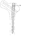
図1は、本発明の実施の形態に係る髄内釘の制御部材を示した斜視図である。
図1では図示を省略したラグスクリューと言われる係合部材の本体に対する固定度を制御するブロッカーと言われる制御部材1は、全体としては略円柱状をなしている。制御部材1の一方端側は、主たるラグスクリューに当接するように2つの突出部3a,3bが形成されている。突出部3aと突出部3bとは、制御部材1が延びている方向に対して垂直方向の位置ではなく、傾斜している位置関係になっている。これは、図12において示しているように本体には貫通孔が傾斜して形成されており、それを主ラグスクリューが挿通しており、押し込まれた結果、この主ラグスクリューに突出部3a,3bのそれぞれが対応するためである。ここで、突出部3aには溝係合部5aが形成され、突出部3bには溝係合部5bが形成されている。溝係合部5a,5bは主ラグスクリューに形成された溝に嵌められる形になり、ラグスクリューの回転を防止する役割を果たすものである。
なお、溝係合部5a,5bの形状、突出部3a,3bの形状についてはラグスクリューの形状(溝を含む)との関係により定まるものである。したがって、必ずしも二つの突出部3aと突出部3bとを形成する必要はなく、すなわち突出部の数は一つでも三つ以上でもよい。また、溝係合部5a,5bについても、全ての突出部に形成される必要もなく、ラグスクリュー側に溝係合部を形成して突出部側に溝を形成してもよい。そして、従来の技術で説明したように、弾性体を用いるなどの各種の技術が用いられればよい。
制御部材1の中央域には、副ラグスクリューを挿通させることが可能なように両側の開口が長穴の形状をなして制御部材1が延びている方向に対して垂直方向の位置ではなく、傾斜する挿通路7が形成されている。また、突出部3a,3bとは逆の位置に相当する挿通路7の図1における上端は上方に向かって割れており、所定幅の割れ目9が形成されている。
また、制御部材1の挿通路7の上に位置するが、その外側面には割れ目9の部分を除いて一回りする張出部11が形成されている。張出部11は、図1における上方に向けて軸心13からの距離が大きくなって張り出す形をしている。
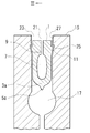
図2は図1の制御部材が髄内釘本体に収納された状態を示す軸方向での端面図であり、図3は図2のIII-IIIライン端面図である。
図2及び図3を参照して、髄内釘本体15には、図12と同様に、貫通孔17と貫通孔19が形成されている。貫通孔17には主ラグスクリューが挿通され、貫通孔19には副ラグスクリューが挿通される。髄内釘本体15には、上端側から貫通孔19を通過して貫通孔17へも繋がる孔21が形成されている。図1の制御部材1はこの孔21の開口23から突出部3a,3bを下にして挿入され、図2及び図3に示したように収納される。孔21の形状は、図2に示す制御部材1の状態において、外側面に沿った形をしている。すなわち、孔21には、張出部11の形状に沿った形の凹んだ窪み部25が上端側に一回りするように形成されている。また、孔21には、最上端部に螺合するネジ溝27が形成されている。なお、後述するように、副ラグスクリューが髄内釘本体15の貫通孔19を挿通するとともに制御部材1の挿通路7を挿通することができるような位置決めが行われる。
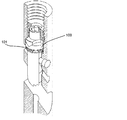
図4は図2に示した状態から主ラグスクリューが挿通された状態を示した図であり、図5は図3に示した状態から主ラグスクリューが挿通された状態を示した図である。
図4及び図5に示すように、主ラグスクリュー29が挿通される。主ラグスクリュー29には、外周の延びる方向に沿って4つの溝31a,31b,31c,31dが形成されている。図4では、溝31dと制御部材1の溝係合部5a,5bとが対向している。なお、ここでの溝31dと溝係合部5a,5bとの位置関係について、図4及び図5に示した状態においては主ラグスクリューの回転を防止できる状態にはないものとしておくが、この状態において主ラグスクリューの回転が阻止される位置関係であっても構わない。
図6は図4に示した状態から副ラグスクリューが挿通された状態を示した図であり、図7は図5に示した状態から副ラグスクリューが挿通された状態を示した図である。
図6及び図7に示すように、副ラグスクリュー33が挿通される。ここでの副ラグスクリュー33は、断面が6角形をしており、制御部材1の挿通路7の下方に配置される。
図8は図6に示した状態からキャップが開口23に嵌められる状態を示した図であり、図9は図7に示した状態からキャップが開口23に嵌められる状態を示した図である。
図8及び図9に示すように、キャップ35には側面に制御部材1の最上端部に形成されたネジ溝27に螺合するネジ溝37が形成されており、これらが互いに螺合して孔21は蓋がなされることになる。
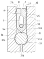
図10は図8に示した状態からキャップ35が螺合により内部に入っていき制御部材1が主ラグスクリュー29及び副ラグスクリュー33を本体15に対する固定度を同時に制御している状態を示した図であり、図11は図9に示した状態からキャップ35が螺合により内部に入っていき制御部材1が主ラグスクリュー29及び副ラグスクリュー33を本体15に対する固定度を同時に制御している状態を示した図である。
図8及び図9に示した状態では、主ラグスクリュー29も副ラグスクリュー33も回転・摺動可能であったとする。以下、制御部材1が主ラグスクリュー29の髄内釘本体15に対する固定度を制御することを説明し、次に副ラグスクリュー33の髄内釘本体15に対する固定度を制御することを説明する。
この状態においてキャップ35が螺合により内部に入っていくと、主ラグスクリュー29は、溝31dと溝係合部5a,5bとの係合により摺動は可能であるが回転が阻止された状態になる。さらには、溝31dと溝係合部5a,5b(或いは突出部3a,3bと主ラグスクリュー29の外周)との間に大きな圧力が加わり、制御部材1が主ラグスクリュー29を貫通孔17の下方側に押し込むように圧接し、図10及び図11に示すように摺動も不可の状態にする。このように、制御部材1は、キャップ35によって押し込まれることにより、主ラグスクリュー29の髄内釘本体15に対する固定度を制御する。
副ラグスクリュー33については、以下のようになる。キャップ35が内部に押し込まれていくと、制御部材1の張出部11と孔21の窪み部25とが接触効力を生じながら制御部材1が下方に下がっていって摺動状態が続く。その摺動に伴い、窪み部25は下方側向かって断面積が小さく、張出部11は上方側向かって断面積が大きいことから、制御部材1の上部側の割れ目9はその間隔を狭くしていくとともに、挿通路7の形状も上方側が狭くなっていく。その結果、まずは副ラグスクリュー33の断面形状が六角形であることからその面或いは複数の角が挿通路7の内壁面に回転を不可とする形で接触する。これにより、副ラグスクリュー33は、摺動は可能であるが、回転が阻止された状態になる。さらに割れ目9の間隔が狭くなって接触するような状態になると、副ラグスクリュー33の外周面と挿通路7の内壁面との間の接触圧力が大きくなり、最終的に、図10及び図11に示すように副ラグスクリュー33の摺動も不可の状態となる。このように、制御部材1は、キャップ35によって押し込まれることにより、副ラグスクリュー33の髄内釘本体15に対する固定度をも制御する。
なお、制御部材1は、上記したように主ラグスクリュー29と副ラグスクリュー33との髄内釘本体15に対する固定度を同時に制御するが、同じタイミングで同じ固定度になることまでは必要ではない。すなわち、例えば、同じタイミングで、主ラグスクリューの摺動が阻止されている状態において副ラグスクリューの回転が阻止されている状態であってもよい。そして、その状態であったとして、その後、さらに制御部材1の下側側が主ラグスクリューに摺動を阻止する状態になるほど当接していることからさらに下方に下がることが不可であって上端側もそのまま下方へ摺動しながらの下がらない場合においても、制御部材の上端側が最上端に向かって狭めるような形状にしておく等して、割れ目9の間隔が狭くなるような状態になって副ラグスクリューの摺動が行われないように形状にしてもよい。
また、制御部材1は対称性があるような形にする必要はなく、挿通路7についても上記の形状に限られない。すなわち、制御部材1の壁面が副ラグスクリューを制御部材の壁面或いは髄内釘本体15の貫通孔19に圧接する場合であってもよい。
さらに、上記では、制御部材1については、張出部11を外周に一回りするように形成し、窪み部25もそれに対応させて一回りするように形成したが、それぞれが一部であってもよい。
さらに、上記では、副ラグスクリューを六角形としたが、他の多角形のほか、制御部材1の形状との関係から、例えば挿通路が楕円ではなく四角形であれば、要求される固定度にもよるが楕円のほか、回転は不可で摺動可能なためには一対の平面状部分をなして摺動も不可なためには一対の円弧のような曲線状部分の組み合わせと言った形状であってもよい。
さらに、上記では、制御部材1が髄内釘本体15の内部である孔21に挿入されて収納された後は、張出部11の最も張り出した上端と窪み部25の最上端との形状の関係から、開口23から抜け難い構造になっているが、このような構造に限定されない。すなわち、例えば、窪み部側は開口に向けて絞られた形状でなく断面積が同一或いはさらに断面積が大きくなる開放する形状であってもよく、孔21側を内側に突出させて抜け難い構造にしてもよい。
さらに、上記では、調整部材としてのキャップは制御部材による固定度を制御することを調整するものとしたが、キャップの下面の中央を突出させて、その突出部分と副ラグスクリューとの接触・係合を可能とし、これによる固定度の制御もさらに行ってもよい。
Claims (5)
- 延びた骨の一端部から髄内に導入されてその軸線に対して交差する複数の貫通孔を有する棒状の本体と、それぞれが前記本体の対応する各貫通孔に挿通されて前記骨に係合可能な複数の係合部材とを備えた髄内釘において、
前記本体の一方端から前記各貫通孔に繋がる孔が形成されており、
前記孔から挿入されて本体内部に収納される部材であって、その一端部が前記複数の係合部材の一つに接触可能であるとともに他の係合部材が挿通できる形状をしており、前記複数の係合部材のそれぞれの前記本体との関係における固定度を同時に制御することが可能な制御部材を含む制御機構を備えた、髄内釘。 - 前記制御機構は、前記制御部材に接触して押し込まれることにより前記制御部材が制御する固定度を調整する調整部材を含む、請求項1記載の髄内釘。
- 前記制御部材は、収納時において、その外側面に、前記軸心に対して前記孔の開口に向かって断面の前記軸心からの距離が大きくなる部分を有し、
前記本体は、前記調整部材が使用される前の状態において、前記制御部材の部分の形状に沿う内壁面の部分を有し、
前記調整部材が使用されることにより前記制御部材の外側面の部分と前記本体の内壁面の部分との間に接触抗力が生じ、前記制御部材の内壁面から生じる圧力を前記挿通している他の係合部材に与えて固定度が調整されることを特徴とする、請求項2記載の髄内釘。 - 前記他の係合部材の形状に関し、前記制御部材の内壁面に面接触又は複数箇所による接触によって回転が防止される形状であることを特徴とする、請求項3記載の髄内釘。
- 延びた骨の一端部から髄内に導入されてその軸線に対して交差する複数の貫通孔を有する棒状の本体と、それぞれが前記本体の対応する各貫通孔に挿通されて前記骨に係合可能な複数の係合部材とを備えた髄内釘に用いられる部材であって、
前記本体の一方端から前記各貫通孔に繋がる孔が形成されており、
前記孔から挿入されて本体内部に収納され、その一端部が前記複数の係合部材の一つに接触可能であるとともに他の係合部材が挿通できる形状をしており、前記複数の係合部材のそれぞれの前記本体との関係における固定度を同時に制御することが可能な制御部材。
Priority Applications (1)
| Application Number | Priority Date | Filing Date | Title |
|---|---|---|---|
| EP08868517.7A EP2253285A4 (en) | 2007-12-28 | 2008-12-24 | MEDULINAL NAIL, AND CONTROL MEMBER USED IN THE NAIL |
Applications Claiming Priority (2)
| Application Number | Priority Date | Filing Date | Title |
|---|---|---|---|
| JP2007338714A JP4374050B2 (ja) | 2007-12-28 | 2007-12-28 | 髄内釘及びそれに用いられる制御部材 |
| JP2007-338714 | 2007-12-28 |
Publications (1)
| Publication Number | Publication Date |
|---|---|
| WO2009084542A1 true WO2009084542A1 (ja) | 2009-07-09 |
Family
ID=40824256
Family Applications (1)
| Application Number | Title | Priority Date | Filing Date |
|---|---|---|---|
| PCT/JP2008/073450 WO2009084542A1 (ja) | 2007-12-28 | 2008-12-24 | 髄内釘及びそれに用いられる制御部材 |
Country Status (3)
| Country | Link |
|---|---|
| EP (1) | EP2253285A4 (ja) |
| JP (1) | JP4374050B2 (ja) |
| WO (1) | WO2009084542A1 (ja) |
Families Citing this family (6)
| Publication number | Priority date | Publication date | Assignee | Title |
|---|---|---|---|---|
| JP6058958B2 (ja) * | 2012-09-24 | 2017-01-11 | 株式会社ホムズ技研 | 髄内固定システム |
| WO2015052841A1 (ja) * | 2013-10-11 | 2015-04-16 | プロスパー株式会社 | 骨接合具および骨接合術 |
| ES2737225T3 (es) | 2015-05-22 | 2020-01-10 | Stryker European Holdings I Llc | Sistema de implante para fijación de hueso |
| JP6434477B2 (ja) * | 2016-12-08 | 2018-12-05 | 株式会社ホムズ技研 | 髄内固定システム |
| JP7052980B2 (ja) * | 2017-06-16 | 2022-04-12 | 株式会社ホムズ技研 | 骨固定装置 |
| US11857228B2 (en) | 2020-03-06 | 2024-01-02 | Stryker European Operations Limited | Set screw for femoral nail |
Citations (5)
| Publication number | Priority date | Publication date | Assignee | Title |
|---|---|---|---|---|
| JPH09164151A (ja) | 1987-12-14 | 1997-06-24 | Howmedica Internatl Inc | 骨髄内転子間骨折固定装置 |
| JPH11318931A (ja) * | 1998-05-20 | 1999-11-24 | Ikufumi Yamada | 遠位横止め抜釘の容易な髄内釘 |
| JP2000342596A (ja) | 1999-06-07 | 2000-12-12 | Homuzu Giken:Kk | 髄内釘 |
| JP2005279140A (ja) | 2004-03-31 | 2005-10-13 | Homuzu Giken:Kk | 髄内釘 |
| JP2005278819A (ja) | 2004-03-29 | 2005-10-13 | Homuzu Giken:Kk | 髄内釘 |
Family Cites Families (3)
| Publication number | Priority date | Publication date | Assignee | Title |
|---|---|---|---|---|
| US6221074B1 (en) * | 1999-06-10 | 2001-04-24 | Orthodyne, Inc. | Femoral intramedullary rod system |
| JP4278289B2 (ja) * | 2000-07-27 | 2009-06-10 | 有限会社ケイオーアイ | 髄内釘 |
| US8092454B2 (en) * | 2004-03-11 | 2012-01-10 | Sohngen Gary W | Fixation instrument for treating a bone fracture |
-
2007
- 2007-12-28 JP JP2007338714A patent/JP4374050B2/ja active Active
-
2008
- 2008-12-24 WO PCT/JP2008/073450 patent/WO2009084542A1/ja active Application Filing
- 2008-12-24 EP EP08868517.7A patent/EP2253285A4/en not_active Withdrawn
Patent Citations (6)
| Publication number | Priority date | Publication date | Assignee | Title |
|---|---|---|---|---|
| JPH09164151A (ja) | 1987-12-14 | 1997-06-24 | Howmedica Internatl Inc | 骨髄内転子間骨折固定装置 |
| JPH1066698A (ja) | 1987-12-14 | 1998-03-10 | Howmedica Internatl Inc | 転子間骨折固定器具 |
| JPH11318931A (ja) * | 1998-05-20 | 1999-11-24 | Ikufumi Yamada | 遠位横止め抜釘の容易な髄内釘 |
| JP2000342596A (ja) | 1999-06-07 | 2000-12-12 | Homuzu Giken:Kk | 髄内釘 |
| JP2005278819A (ja) | 2004-03-29 | 2005-10-13 | Homuzu Giken:Kk | 髄内釘 |
| JP2005279140A (ja) | 2004-03-31 | 2005-10-13 | Homuzu Giken:Kk | 髄内釘 |
Non-Patent Citations (1)
| Title |
|---|
| See also references of EP2253285A4 * |
Also Published As
| Publication number | Publication date |
|---|---|
| JP4374050B2 (ja) | 2009-12-02 |
| EP2253285A4 (en) | 2013-10-02 |
| JP2009153939A (ja) | 2009-07-16 |
| EP2253285A1 (en) | 2010-11-24 |
Similar Documents
| Publication | Publication Date | Title |
|---|---|---|
| WO2009084542A1 (ja) | 髄内釘及びそれに用いられる制御部材 | |
| US8690925B2 (en) | Locking device for locking a rod-shaped element in a receiving part of a bone anchor and bone anchor with such a locking device | |
| US7686834B2 (en) | Anchoring member with safety ring | |
| AU2016341736B2 (en) | Surgical screw and fusion device using same | |
| US8771320B2 (en) | Locking assembly for a polyaxial bone anchoring device | |
| ES2565234T3 (es) | Sistema de fijación de fracturas | |
| US20160361096A1 (en) | Pedicle screw with tulip | |
| US10258397B2 (en) | Bone anchor and bone anchoring assembly comprising the same | |
| US8034054B2 (en) | Intramedullary bone device | |
| US9498253B2 (en) | Polyaxial bone anchoring device | |
| US9339302B2 (en) | Polyaxial bone anchoring device | |
| JP2005040586A (ja) | 骨接合プレートまたは類似のインプラントおよび球状ソケット | |
| JPH078505A (ja) | 椎骨継手 | |
| JP7426251B2 (ja) | ロッドを骨または椎骨に固定するための固定アセンブリ | |
| JP2016514506A (ja) | 脊柱安定化システム及び脊柱安定化システムのための外科用固締要素 | |
| EP3437576B1 (en) | Stabilization device for bones or vertebrae | |
| US9468481B2 (en) | Anti-backout mechanism for orthopedic devices | |
| US10667828B2 (en) | Instrument guide assembly for a bone plate and kit of a bone plate with such an instrument guide assembly | |
| KR20220115923A (ko) | 패스너들을 갖는 뼈 고정 시스템 및 패스너들을 결합 해제시키기 위한 제거 도구 | |
| JP6074259B2 (ja) | 髄内固定システム | |
| US11259850B2 (en) | Femur fixation apparatus | |
| ES2523021T3 (es) | Sistema médico y partes del sistema para ajustar espacialmente un dispositivo de direccionamiento con respecto a un implante corporal | |
| EP3468485B1 (en) | Bone screw |
Legal Events
| Date | Code | Title | Description |
|---|---|---|---|
| DPE2 | Request for preliminary examination filed before expiration of 19th month from priority date (pct application filed from 20040101) | ||
| 121 | Ep: the epo has been informed by wipo that ep was designated in this application |
Ref document number: 08868517 Country of ref document: EP Kind code of ref document: A1 |
|
| NENP | Non-entry into the national phase |
Ref country code: DE |
|
| WWE | Wipo information: entry into national phase |
Ref document number: 2008868517 Country of ref document: EP |