WO2009000527A1 - Representation system - Google Patents
Representation system Download PDFInfo
- Publication number
- WO2009000527A1 WO2009000527A1 PCT/EP2008/005171 EP2008005171W WO2009000527A1 WO 2009000527 A1 WO2009000527 A1 WO 2009000527A1 EP 2008005171 W EP2008005171 W EP 2008005171W WO 2009000527 A1 WO2009000527 A1 WO 2009000527A1
- Authority
- WO
- WIPO (PCT)
- Prior art keywords
- viewing
- image
- grid
- given
- motif image
- Prior art date
Links
Classifications
-
- B—PERFORMING OPERATIONS; TRANSPORTING
- B42—BOOKBINDING; ALBUMS; FILES; SPECIAL PRINTED MATTER
- B42D—BOOKS; BOOK COVERS; LOOSE LEAVES; PRINTED MATTER CHARACTERISED BY IDENTIFICATION OR SECURITY FEATURES; PRINTED MATTER OF SPECIAL FORMAT OR STYLE NOT OTHERWISE PROVIDED FOR; DEVICES FOR USE THEREWITH AND NOT OTHERWISE PROVIDED FOR; MOVABLE-STRIP WRITING OR READING APPARATUS
- B42D25/00—Information-bearing cards or sheet-like structures characterised by identification or security features; Manufacture thereof
- B42D25/20—Information-bearing cards or sheet-like structures characterised by identification or security features; Manufacture thereof characterised by a particular use or purpose
- B42D25/29—Securities; Bank notes
-
- B—PERFORMING OPERATIONS; TRANSPORTING
- B42—BOOKBINDING; ALBUMS; FILES; SPECIAL PRINTED MATTER
- B42D—BOOKS; BOOK COVERS; LOOSE LEAVES; PRINTED MATTER CHARACTERISED BY IDENTIFICATION OR SECURITY FEATURES; PRINTED MATTER OF SPECIAL FORMAT OR STYLE NOT OTHERWISE PROVIDED FOR; DEVICES FOR USE THEREWITH AND NOT OTHERWISE PROVIDED FOR; MOVABLE-STRIP WRITING OR READING APPARATUS
- B42D25/00—Information-bearing cards or sheet-like structures characterised by identification or security features; Manufacture thereof
- B42D25/20—Information-bearing cards or sheet-like structures characterised by identification or security features; Manufacture thereof characterised by a particular use or purpose
- B42D25/23—Identity cards
-
- B—PERFORMING OPERATIONS; TRANSPORTING
- B42—BOOKBINDING; ALBUMS; FILES; SPECIAL PRINTED MATTER
- B42D—BOOKS; BOOK COVERS; LOOSE LEAVES; PRINTED MATTER CHARACTERISED BY IDENTIFICATION OR SECURITY FEATURES; PRINTED MATTER OF SPECIAL FORMAT OR STYLE NOT OTHERWISE PROVIDED FOR; DEVICES FOR USE THEREWITH AND NOT OTHERWISE PROVIDED FOR; MOVABLE-STRIP WRITING OR READING APPARATUS
- B42D25/00—Information-bearing cards or sheet-like structures characterised by identification or security features; Manufacture thereof
- B42D25/30—Identification or security features, e.g. for preventing forgery
- B42D25/324—Reliefs
-
- B—PERFORMING OPERATIONS; TRANSPORTING
- B42—BOOKBINDING; ALBUMS; FILES; SPECIAL PRINTED MATTER
- B42D—BOOKS; BOOK COVERS; LOOSE LEAVES; PRINTED MATTER CHARACTERISED BY IDENTIFICATION OR SECURITY FEATURES; PRINTED MATTER OF SPECIAL FORMAT OR STYLE NOT OTHERWISE PROVIDED FOR; DEVICES FOR USE THEREWITH AND NOT OTHERWISE PROVIDED FOR; MOVABLE-STRIP WRITING OR READING APPARATUS
- B42D25/00—Information-bearing cards or sheet-like structures characterised by identification or security features; Manufacture thereof
- B42D25/30—Identification or security features, e.g. for preventing forgery
- B42D25/342—Moiré effects
-
- B—PERFORMING OPERATIONS; TRANSPORTING
- B44—DECORATIVE ARTS
- B44F—SPECIAL DESIGNS OR PICTURES
- B44F1/00—Designs or pictures characterised by special or unusual light effects
- B44F1/08—Designs or pictures characterised by special or unusual light effects characterised by colour effects
- B44F1/10—Changing, amusing, or secret pictures
-
- B—PERFORMING OPERATIONS; TRANSPORTING
- B44—DECORATIVE ARTS
- B44F—SPECIAL DESIGNS OR PICTURES
- B44F7/00—Designs imitating three-dimensional effects
-
- B42D2035/20—
Definitions
- the invention relates to a representation arrangement for security papers, documents of value, electronic display devices or other data carriers for representing one or more predetermined three-dimensional Kör per (s).
- Data carriers such as valuables or identity documents, but also other objects of value, such as branded articles, are often provided with security elements for the purpose of security, which permit verification of the authenticity of the data carrier and at the same time serve as protection against unauthorized reproduction.
- Data carriers in the context of the present invention are in particular banknotes, stocks, bonds, certificates, vouchers, checks, high-quality admission tickets, but also other forgery-prone papers, such as passports and other identity documents, credit cards, health cards and product security elements such as labels, seals, packaging and the like.
- the term "data carrier” in the following includes all such objects, documents and product protection means.
- the security elements may be in the form of, for example, a security thread embedded in a banknote, a tearing thread for product packaging, an applied security strip, a cover sheet for a banknote with a through opening or a self-supporting transfer element, such as a patch or label after its manufacture is applied to a document of value.
- Security elements with optically variable elements which give the viewer a different image impression at different viewing angles, play a special role, since they can not be reproduced even with high-quality color copying machines.
- security elements can be equipped with security features in the form of diffraction-optically active microstructures or nanostructures, such as with conventional embossing holograms or other hologram-like diffraction structures, as described, for example, in the publications EP 0 330 733 A1 or EP 0 064 067 A1.
- US Pat. No. 5,712,731 A discloses the use of a moire magnification arrangement as a security feature.
- the security device described therein has a regular array of substantially identical printed microimages of up to 250 ⁇ m in size and a regular two-dimensional array of substantially identical spherical microlenses.
- the microlens arrangement has essentially the same pitch as the microimage arrangement. If the micro-image arrangement is viewed by the microlens array, then in the areas in which the two arrangements are substantially in register, one or more enlarged versions of the microimages are generated for the viewer.
- moire magnification thereafter refers to a phenomenon that occurs when viewing a raster of identical image objects through a lenticular grid of approximately the same pitch. As with any pair of similar rasters, this results in a moire pattern, which in this case is magnified and optionally rotated image of the repeated elements of the image grid appears.
- the present invention seeks to avoid the disadvantages of the prior art and in particular to provide a generictechnischsan extract that offers a lot of leeway in the design of the motif images to be considered.
- a generic representation arrangement includes a raster image arrangement for displaying a given three-dimensional body, which is given by a body function f (x, y, z)
- a viewing grid of a plurality of viewing elements for displaying the predetermined body when viewing the motif image using the viewing grid
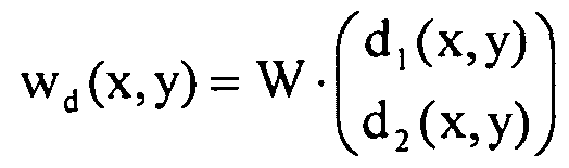
- magnification term V (x, y, x m , ym) is either a scalar
- V (x, y, x m, y m) f Z ⁇ (x 'y' Xn "ym) - ll is connected to the effective distance
- the vector (d (x, y), C2 (x, y)) with 0 ⁇ c, (x, y), c 2 (x, y) ⁇ 1 indicates the relative position of the center of the viewing elements within the cells of the motif image .
- the vector (Ci 1 (X 7 Y), d 2 (x, y)) with 0 ⁇ d, (x, y), d 2 (x, y) ⁇ 1 represents a shift of the cell boundaries in the motif image
- g (x, y) is a mask function for adjusting the visibility of the body.
- magnification term V can represent either a scalar or a matrix, so that no unique name with lowercase or uppercase letters is possible. In the context, however, it always becomes clear whether a scalar, a matrix, or both alternatives come into question.
- the invention generally relates to the generation of three-dimensional images and to three-dimensional images with varying image contents when the direction of viewing changes.
- the three-dimensional images are referred to as body in the context of this description.
- body refers in particular to sets of points, line systems or patches in three-dimensional space, by which three-dimensional "bodies” are described by mathematical means.
- more than one value can be considered, from which a value is formed or selected according to rules to be determined becomes. This selection can be made, for example, by specifying an additional characteristic function, as explained below using the example of an opaque body and a transparency step function given in addition to the body function f.
- the representation arrangement according to the invention contains a raster image arrangement in which a motif (or the predetermined body) appears to float individually or not necessarily as an array in front of or behind the image plane or penetrates it.
- the illustrated three-dimensional image moves in tilting of the security element, which is formed by the superimposed motif image and the viewing grid in predetermined by the magnification and movement matrix A directions.
- the motif image is not produced photographically, not even by an exposure grating, but mathematically constructed with a modulo algorithm, whereby a variety of different magnification and motion effects can be generated, which are described in more detail below.
- the image to be represented consists of individual motifs which are periodically arranged in a grid.
- the motif image to be viewed through the lenses represents a greatly reduced version of the image to be displayed, with the area associated with each individual motif corresponding at most to approximately one lens cell. Due to the small size of the lens cells, only relatively simple entities can be considered as individual motifs.
- the illustrated three-dimensional image is generally a single image, and does not necessarily have to be composed of a grid of periodically repeated individual motifs.
- the three-dimensional image depicted may represent a complex, high-resolution image frame.
- the name component "moire” is used for embodiments in which the moiré effect is involved, in the use of the name component “modulo” a moiré effect is not necessarily involved.
- the name component “Mapping” indicates any illustrations, while the name component “Magnifier” indicates that not any illustrations but only enlargements are involved.
- the expression s mod W represents a reduction of the vector s into the fundamental mesh of the lattice described by the matrix W (the "phase" of FIG Vector s inside the grid W).
- a transparency step function t (x, y, z) is given, where t (x, y, z) is equal to 1 when the body f (x, y, z) obscures the background at the location (x, y, z) and otherwise equals 0.
- t x, y, z
- the smallest value for z.sub.k (x, y, Xm, ym) is taken for which t (x, y, z.sub.k) is not equal to zero in order to view the front of the body from the outside ,
- the largest value for which t (x, y, z ⁇ ) is not equal to zero can also be taken.
- a deeply-reversed (pseudoscopic) image emerges, in which the back of the body is viewed from the inside.
- the values z.sub.k (x, y, Xm, ym) may assume positive or negative values, or be 0, depending on the position of the body with respect to the drawing plane (penetrating behind or in front of the drawing plane or the drawing plane).
- a generic representation arrangement includes a raster image arrangement for displaying a predetermined three-dimensional body by a height profile with a two-dimensional representation of the body f (x, y) and a height function z (x, y) is given, which contains height / depth information for each point (x, y) of the given body
- a viewing grid of a plurality of viewing elements for displaying the predetermined body when viewing the motif image using the viewing grid
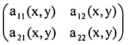
- V (x, y) (A (x, y) - I), where the matrix A (x, y) Describes a desired magnification and movement behavior of the given body, and I is the unit matrix,
- d2 (x, y)) with 0 ⁇ d, (x, y), d 2 (x, y) ⁇ 1 represents a shift of the cell boundaries in the motif image
- - g (x> y) is eme mask function for adjusting the visibility of the body.
- This elevation profile model uses a two-dimensional drawing f (x, y) of a body to simplify the calculation of the motif image, wherein an additional z-coordinate z is applied to each point x, y of the two-dimensional image of the body (x, y) indicates height / depth information for that point.
- the two-dimensional drawing f (x, y) is a brightness distribution (grayscale image), a color distribution (color image), a binary distribution (line drawing) or a distribution of other image characteristics such as transparency, reflectivity, density or the like.
- the illustrated body moves in this variant when viewed with eye relief in the x-direction and tilting of the array in the x direction in the direction of ⁇ i to the x-axis. When tilting in the y direction, there is no movement.
- the viewing grid can also be a split screen, cylindrical lens grid or cylinder cavity mirror grid, the unit cell through given with the gap or cylinder axis distance d.
- the cylindrical lens axis lies in the y-direction.
- the pattern hereby generated for the print or embossed image to be created behind a lenticular screen W can be viewed not only with the slit diaphragm or cylindrical lens array with axis in the direction ⁇ , but also with a pinhole or lens array
- ß can be arbitrary.
- Another variant describes an orthoparallactic 3D effect.
- Z 1 can be positive or negative or even 0.
- f j (x, y) is the image function of the j-th intersection, and the transparency step function t j (x, y) equals 1 if the intersection j obscures objects behind it (x, y) and is otherwise equal to 0.
- the representation arrangement contains
- a motif image which is divided into a plurality of cells, in each of which imaged areas of the predetermined body are arranged, and
- a viewing grid of a plurality of viewing elements for displaying the predetermined body when viewing the motif image using the viewing grid
- the vector (ci (x, y), C2 (x, y)) with 0 ⁇ c, (x, y), c 2 (x, y) ⁇ 1 indicates the relative position of the center of the viewing elements within the cells of the motif image .
- the vector (di (x, y), d2 (x, y)) with O ⁇ d, (x, y), d 2 (x, y) ⁇ 1 represents a shift of the cell boundaries in the motif image
- g (x, y) is a mask function for adjusting the visibility of the body.
- Z j > Z 1-1 lie.
- fj (x, y) is the image function of the jth section which can indicate a brightness distribution (grayscale image), a color distribution (color image), a binary distribution (line drawing) or other image properties such as transparency, reflectivity, density or the like ,
- the transparency step function t j (x, y) is equal to 1 if the section j obscures objects lying behind it at the point (x, y) and otherwise equals 0.
- the viewing grid can also be a split screen or cylinder lens grid with the gap or cylinder axis spacing be d. If the cylindrical lens axis lies in the y direction, the unit cell of the viewing grid is through given.
- the motif image with a pinhole diaphragm can also be used here.
- the viewing elements of the viewing grid are preferably arranged periodically or locally periodically, with the local period parameters preferably changing only slowly in relation to the periodicity length in the latter case.
- the periodicity length or the local periodicity length is preferably between 3 ⁇ m and 50 ⁇ m, preferably between 5 ⁇ m and 30 ⁇ m, particularly preferably between about 10 ⁇ m and about 20 ⁇ m.
- An abrupt change in the periodicity length is also possible if it was previously kept constant or nearly constant over a length which is large in comparison to the periodicity length, for example for more than 20, 50 or 100 periodicity lengths.
- the viewing elements can be formed in all aspects of the invention by non-cylindrical microlenses, in particular by microlenses with a circular or polygonal limited base surface, or by elongated cylindrical lenses whose extension in the longitudinal direction more than 250 microns, preferably more than 300 microns, more preferably more than 500 ⁇ m and in particular more than 1 mm.
- the viewing elements are provided by pinhole apertures, slotted apertures, apertured apertured or slotted apertures, aspherical lenses, Fresnel lenses, GRIN (Gradient Refraction Index) lenses, zonal plates, holographic lenses, concave mirrors, Fresnel mirrors, zone mirrors or other elements focussing or hiding effect formed.
- the carrier of the image function it is provided that the carrier of the image function
- the illustrated three-dimensional image has, in advantageous embodiments, no periodicity, ie is a representation of a single 3D motif.
- the viewing grid and the motif image of the presentation arrangement are firmly connected to one another and thus form a security element with a viewing grid and motif image arranged at a distance one above the other.
- the motif image and the viewing grid are advantageously arranged on opposite surfaces of an optical spacer layer.
- the security element may be, in particular, a security thread, a tear thread, a security tape, a security strip, a patch or a label for application to a security paper, value document or the like.
- the total thickness of the security element is preferably below 50 ⁇ m, preferably below 30 ⁇ m and particularly preferably below 20 ⁇ m.
- the viewing grid and the motif image of the presentation arrangement are thus attached to one another. arranged at different locations of a data carrier that the viewing grid and the motif image for self-authentication are superimposed and form a security element in the superimposed state.
- the viewing grid and the motif image can be superimposed in particular by bending, folding, bending or folding the data carrier.
- the motif image is displayed by an electronic display device and the viewing grid for viewing the displayed motif image is firmly connected to the electronic display device.
- the viewing grid can also be a separate viewing grid, which can be brought onto or in front of the electronic display device for viewing the displayed motif image.
- the security element can thus be formed both as a permanent security element by a viewing grid and motif image fixedly connected to one another, as well as by a spatially separated viewing grid and an associated motif image, wherein the two elements form a temporarily present security element when superimposed.
- Statements in the description about the movement behavior or the visual impression of the security element relate both to firmly connected permanent security elements and to superimposed temporary security elements.
- the cell boundaries in the motif image may advantageously be spatially independent, so that the vector (di (x, y), d2 (x, y)) occurring in the image function m (x, y) is constant.
- the cell boundaries in the motif image may also be spatially dependent.
- the motif image may have two or more subareas with different, each constant cell grid.
- a location-dependent vector (d 1 (x, y) / d 2 (x, y)) can also be used to define the outline of the cells in the motif image. For example, instead of parallelogram-shaped cells, it is also possible to use cells with a different uniform shape that match one another in such a way that the area of the motif image is filled up completely (tiling of the surface of the motif image).
- the location-dependent vector (di (x, y), d2 (x, y))
- the cell shape can be set as desired. As a result, the designer has particular influence on which viewing angles subject jumps occur.
- the motif image can also be subdivided into different regions, in which the cells each have identical shape, while the cell shapes differ in the different regions. This causes parts of the motif, which are assigned to different areas, to jump at different tilt angles when tilting the security element. If the areas with different cells are large enough that they can be seen with the naked eye, additional visible information can be accommodated in the security element in this way. On the other hand, if the areas are microscopic, ie can only be seen with magnifying aids, additional hidden information can be accommodated in the security element in this way, which can serve as a higher-level security feature.
- a location-dependent vector (d 1 (x, y), d 2 (x, y)) can also be used to generate cells, all of which are mutually different in shape differ. As a result, it is possible to generate a completely individual security feature that can be tested, for example, by means of a microscope.
- the mask function g occurring in the image function m (x, y) of all variants of the invention is advantageously identical in many cases. 1.
- the mask function g is zero in subareas, in particular in edge regions of the cells of the motif image, and then limited the solid angle area under which the three-dimensional image can be seen.
- the mask function can also describe an image field limitation in which the three-dimensional image is not visible, as explained in more detail below.
- the relative position of the center of the viewing elements within the cells of the motif image is location-independent, ie the vector (ci (x, y), C2 (x, y)) is constant. In other embodiments, however, it may also be appropriate to make the relative position of the center of the viewing elements within the cells of the motif image location-dependent, as explained in more detail below.
- the motif image for enhancing the three-dimensional visual impression is filled with Fresnel structures, blazed gratings or other optically active structures.
- a viewing grid of a plurality of viewing elements for displaying the predetermined bodies when viewing the motif image using the viewing grid
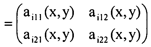
- I a l21 (x, y, x m , y m ) a l22 (x, y, x m , y m ) J describe the desired magnification and movement behavior of the given body fi and I is the unit matrix,
- gi (x, y) are mask functions for adjusting the visibility of the body fi.
- ZiK (X z Y z Xm Z Ym) ie the z coordinate of a common point of the visual line with the body i u , more than one value can be considered, from which a value is formed or selected according to rules to be determined.
- a transparency step function (characteristic function) ti (x, y, z) may be given, where ti (x, y, z) is equal to 1 when the body fi (x, y, z) at the location (x, y, z) obscures the background and otherwise equals 0.
- the values Zi ⁇ (x, y, Xm, ym) may, depending on the position of the body in relation to the plane of the drawing (penetrating behind or in front of the drawing plane or the drawing plane), either assume positive or negative values or be zero.
- ti (x, y, z) is equal to 1 when the body fi (FIG. x, y, z) obscures the background at the location (x, y, z) and otherwise equals 0.
- the smallest value for Zi ⁇ (x, y, Xm, ym) for which ti (x, y, z ⁇ ) is not equal to zero is the body front side of the body to look at fi from the outside.
- the largest value can also be taken for which ti (x, y, z ⁇ ) is not equal to zero in order to view the body back of the body fi from the inside.
- a depiction arrangement according to a fifth aspect of the invention corresponding to the elevation profile model of the second aspect of the invention contains a raster image arrangement for depicting a plurality of predefined objects.
- a viewing grid of a plurality of viewing elements for displaying the predetermined bodies when viewing the motif image using the viewing grid
- magnification terms Vi (x, y) are either scalars
- each a desired magnification describe the behavior and movement behavior of the given body fi and I is the unit matrix
- a representation arrangement according to a sixth aspect of the invention corresponding to the sectional plane model of the third aspect of the invention comprises a raster image arrangement for representing a plurality (N ⁇ l) of the invention.
- a viewing grid of a plurality of viewing elements for displaying the predetermined bodies when viewing the motif image using the viewing grid
- m (x, y) F (h u, u h, ..., h ln ⁇ , h 2], h 22, ... h 2ni, ..., h m, h N2, ..., h NnN ) / with the descriptive functions
- Zi j is minimum or maximum
- 2 described and in the matrix W w 22.
- the vectors (dii (x, y), di2 (x, y)) with O ⁇ (I 11 (X, y), d l2 (x, y) ⁇ 1 represent respectively a shift of the cell boundaries in the motif image
- gi j (x, y) are mask functions for adjusting the visibility of the body fi.
- All embodiments made in the first three aspects of the invention for individual bodies f also apply to the plurality of bodies U of the more general raster image arrangements of the fourth to sixth aspects of the invention.
- at least one (or all) of the descriptive functions of the fourth, fifth or sixth aspect of the invention may be designed as indicated above for the image function m (x, y) of the first, second or third aspect of the invention.
- the raster image arrangement represents a change picture, a motion picture or a morph picture.
- the mask functions gi or gi j can in this case in particular define a strip-like or checkerboard-like change of the visibility of the body fi.
- An image sequence can advantageously take place when tilting along a predetermined direction; in this case it is useful to use stripe-like mask functions gi and g ,, respectively, ie mask functions which are nonzero for each i only in a strip traveling within the unit cell. In the general case, however, it is also possible to select mask functions which allow a sequence of images to take place by means of curved, meandering or spiral tilting movements.
- the invention While in alternating images (tilt images) or other motion pictures ideally only one three-dimensional image is simultaneously visible, the invention also includes designs in which for the viewer two or more three-dimensional images (body) fi are visible at the same time.
- the master function F advantageously represents the sum function, the maximum function, an OR link, an XOR link or another logical link.
- the motif image is present in particular in an embossed or printed layer.
- the security element has in all aspects an opaque cover layer for covering the raster image arrangement by area.
- This cover layer is advantageously in the form of patterns, characters or codes before and / or has recesses in the form of patterns, characters or codes.
- the spacer layer may comprise, for example, a plastic film and / or a lacquer layer.
- the permanent security element itself in all aspects of the invention preferably represents a security thread, a tear thread, a security strip, a security strip, a patch or a label for application to a security paper, document of value or the like.
- the security element can form a transparent or recessed area Span the disk. Different appearances can be realized on different sides of the data carrier. Also two-sided designs come into question, in which both sides of a motif image viewing grid are arranged.
- the raster image arrangements according to the invention can be combined with other security features, for example with diffractive structures, with hologram structures in all variants, metallized or non-metallized, with sub-wavelength structures, metallized or non-metallized, with subwavelength gratings, with layer systems which show a color change on tilting, semitransparent or opaque , with diffractive optical elements, with refractive optical elements, such as prism beam shaper, with special hole shapes, with safety features with specifically adjusted electrical conductivity, with incorporated materials with magnetic coding, with substances with phosphorescent, fluorescent or luminescent effect, with safety features based on liquid crystals, with matt structures, with micromirrors, with elements with a louvre effect or with sawtooth structures.
- Further security features with which the inventive grid tersentan angelen can be combined, are given in the document WO 2005/052650 A2 on pages 71 to 73; These are included in the present description.
- the image contents of individual cells of the motif image can be interchanged with one another after the determination of the image function m (x, y).
- the invention also includes methods for producing the representational arrangements according to the first to sixth aspects of the invention, in which a motif image is calculated from one or more predetermined three-dimensional bodies.
- a motif image is calculated from one or more predetermined three-dimensional bodies.
- the procedure and the required mathematical relationships for the general perspective, the height profile model and the sectional plane model have already been indicated above and are also explained in more detail by the following exemplary embodiments.
- the size of the motif picture elements and the viewing elements is within the scope of the invention typically about 5 to 50 microns, so that the influence of modulo magnification on the thickness of the security elements can be kept low.
- the production of such small lens arrays and such small images is described for example in the document DE 10 2005 028162 A1, the disclosure of which is incorporated in the present application in this respect.
- a typical procedure is as follows: For the production of microstructures (microlenses, micromirrors, microimage elements), techniques of semiconductor structuring can be used, for example photolithography or electron beam lithography.
- a particularly suitable method is to expose the structures in photoresist by means of a focused laser beam. Subsequently, the structures, which may have binary or more complex three-dimensional cross-sectional profiles, are exposed with a developer.
- laser ablation can be used.
- the original obtained in one of these ways can be further processed into a stamping tool with the aid of which the structures can be duplicated, for example, by embossing in UV varnish, thermoplastic embossing or by the microtip printing technique described in document WO 2008/00350 A1.
- the latter technique is a micro-gravure technique that combines the advantages of printing and embossing technologies. Details of this micro-gravure printing process and the associated advantages can be found in the publication WO 2008/00350 A1, the disclosure content of which is incorporated in the present application in this respect.
- embossed with metal stamping structures coloring by metallic nanostructures, embossing in colored UV varnish, micro gravure printing according to the document WO 2008/00350 Al, coloring the embossed structures and then scraping the embossed film, or the method described in German Patent Application 10 2007062089.8 for the selective transfer of an imprint material to elevations or depressions of an embossed structure.
- the subject image may be written directly into a photosensitive layer with a focused laser beam.
- the microlens array can also be made by laser ablation or grayscale lithography. Alternatively, a binary exposure can be carried out, wherein the lens shape is formed only later by melting of the photoresist ("thermal reflow") .On the original, as in the case of the microstructure array, an embossing tool can be produced with the aid of which mass production can take place, for example by embossing in UV varnish or thermoplastic embossing.
- the size of the images and lenses to be inserted is about 50 up to 1000 ⁇ m.
- the motif images to be introduced can be printed in color using conventional printing methods, such as offset printing, gravure printing, letterpress printing, screen printing, or digital printing methods, such as ink jet printing or laser printing.
- the modulo-magnifier principle or modulo-mapping principle according to the invention can also be used in the case of three-dimensional computer and television Images that are generally displayed on an electronic display device.
- the size of the images to be introduced and the size of the lenses in the lens array to be mounted in front of the screen in this case is about 50 to 500 microns.
- the screen resolution should be at least an order of magnitude better, so that high-resolution screens are required for this application.
- the invention also includes a security paper for the production of security or value documents, such as banknotes, checks, identity cards, documents or the like, with a representation arrangement of the type described above.
- the invention further includes a data carrier, in particular a branded article, a value document, a decorative article, such as a package, postcards or the like with a representation arrangement of the type described above.
- the viewing grid and / or the motif image of the presentation arrangement can be arranged over the entire surface, on partial surfaces or in a window region of the data carrier.
- the invention also relates to an electronic display device having an electronic display device, in particular a computer or television screen, a control device and a display device of the type described above.
- the control device is designed and configured to display the motif image of the display device on the electronic display device.
- FIG. 1 is a schematic representation of a banknote with an embedded security thread and a glued transfer element
- FIG. 3 schematically shows a side view of a body to be displayed in space, which is to be shown in perspective in a scene image plane, and
- Fig. 1 shows a schematic representation of a banknote 10, which is provided with two security elements 12 and 16 according to embodiments of the invention.
- the first security element represents a security thread 12 that emerges in certain window regions 14 on the surface of the banknote 10 while it is embedded in the intervening areas inside the banknote 10.
- the second security element is formed by a glued transfer element 16 of any shape.
- the security element 16 can also be designed in the form of a cover film, which is arranged over a window area or a through opening of the banknote.
- the security element may be designed for viewing in supervision, review or viewing both in supervision and in review.
- Both the security thread 12 and the transfer element 16 may include a modulo magnification arrangement according to an embodiment of the invention.
- the mode of operation and the production method according to the invention for such arrangements will be described in more detail below with reference to the transfer element 16.
- the transfer element 16 includes a carrier 20 in the form of a transparent plastic film, in the embodiment of an approximately 20 micron thick polyethylene terephthalate (PET) - film.
- the upper side of the carrier film 20 is provided with a grid-like arrangement of microlenses 22 which form on the surface of the carrier film a two-dimensional Bravais grid with a preselected symmetry.
- the Bravais lattice may have hexagonal lattice symmetry.
- other, in particular lower symmetries and thus more general forms, such as the symmetry of a parallelogram grating are also possible.
- the spacing of adjacent microlenses 22 is preferably chosen as small as possible in order to ensure the highest possible area coverage and thus a high-contrast representation.
- the spherically or aspherically configured microlenses 22 preferably have a diameter between 5 .mu.m and 50 .mu.m and in particular a diameter between only 10 .mu.m and 35 .mu.m and are therefore not visible to the naked eye. It is understood that in other designs, larger or smaller dimensions come into question.
- the microlenses can have a diameter of between 50 ⁇ m and 5 mm for decorative purposes, while dimensions of less than 5 ⁇ m can also be used for modulo magnification arrangements which can only be deciphered with a magnifying glass or a microscope.
- a motif layer 26 is arranged, which contains a divided into a plurality of cells 24 motif image with Motivlag- elements 28.
- the optical thickness of the carrier film 20 and the focal length of the microlenses 22 are coordinated so that the motif layer 26 is located approximately at a distance of the lens focal length.
- the carrier film 20 thus forms a optical spacer layer, which ensures a desired, constant distance of the microlenses 22 and the motif layer 26 with the motif image.
- FIG. 3 shows very diagrammatically a side view of a body 30 in space, which is to be shown in perspective in the motif image plane 32, which is also referred to below as the drawing plane.
- the body 30 is generally described by a body function f (x, y, z) and a transparency step function t (x, y, z), where the z-axis is perpendicular to the plane of the drawing spanned by the x and y axes 32 stands.
- the body function f (x, y, z) indicates a characteristic property of the body at the point (x, y, z), for example a brightness distribution, a color distribution, a binary distribution or other body properties, such as transparency, reflectivity, density or similar. In general, therefore, it can represent not only a scalar function but also a vector-valued function of the location coordinates x, y and z.
- the transparency step function t (x, y, z) is equal to 1 if the body obscures the background at the point (x, y, z) and is otherwise, ie in particular if the body is at the point (x, y, z).
- y, z) is transparent or absent, equal to 0.
- the three-dimensional image to be displayed may comprise not only a single object but also a plurality of three-dimensional objects which need not necessarily be related.
- body used in this description is used in the sense of any three-dimensional structure and includes structures with one or more separate three-dimensional objects.
- the arrangement of the microlenses in the lens plane 34 is described by a two-dimensional Bravais grating whose unit cell is indicated by vectors wi and W2 (with the components w,, w 21 and w n , W 11, respectively).
- the unit cell may be indicated in matrix form by a lenticular array W:
- the lenticular matrix W is often referred to simply as a lens matrix or lenticular array hereinafter.
- the term pupil plane is also used below.
- the positions x m , y m in the pupil plane designated below as pupil positions represent the grid points of the W grid in the lens plane 34.
- lens plane 34 instead of lenses 22, it is also possible, for example, to use pinholes on the principle of the pinhole camera.
- lenses and imaging systems such as aspherical lenses, cylindrical lenses, slit diaphragms, mirrored apertured or slit diaphragms, Fresnel lenses, GRIN lenses (Gradient Refraction Index), zone plates (diffractive lenses), holographic lenses, concave mirrors, Fresnel mirrors, zone mirrors and other elements with focussing or also fading effect, can be used as viewing elements in the viewing grid.
- elements with focussing effect are used as viewing elements in the viewing grid.
- elements with ausblendender effect are used as viewing elements in the viewing grid.
- the observer gazes through the motif image which in this case is partially transparent, onto the underlying mirror array and sees the individual small mirrors as bright or dark points from which the image to be displayed is built.
- the motif image is generally so finely structured that it can only be seen as a veil.
- the formulas described for the relationships between the image to be displayed and the motif image apply, even if this is not mentioned in detail, not only for lenticular, but also for mirror grid. It is understood that in the inventive use of concave mirrors in place of the lens focal length, the mirror focal length occurs.
- the viewing direction from below is to be considered in FIG. 2, and in FIG. 3 the planes 32 and 34 are interchanged with one another in the case of the mirror array arrangement.
- the description of the invention is based on lens grids, which are representative of all other viewing grids used in the invention.
- e denotes the lens focal length (in general, the lens data and the refractive index of the medium between the lens grid and the motif grid are taken into account in the effective distance e).
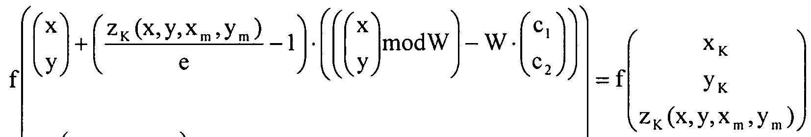
- a point (x ⁇ , y ⁇ , z ⁇ ) of the body 30 in space is projected in perspective in the plane of the drawing 32 with the pupil position (x m , y m , 0).
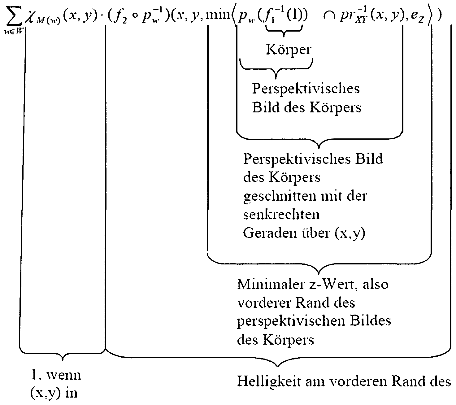
- the motif image in the motif plane 32 which generates a representation of the desired body when viewed through the lenticular grid W arranged in the lens plane 34, is represented by an image function m (x , y), which according to the invention is given by:
- the vector (ci, C 2 ), which in the general case can be location-dependent, that is by (ci (x, y), c 2 (x, y)) with 0 ⁇ c, (x, y), c 2 (x , y) ⁇ 1, indicates the relative position of the center of the viewing elements within the cells of the motif image.
- the coefficients of A are chosen such that the raster image arrangement represents the predetermined body.
- the height profile is based on a two-dimensional drawing f (x, y) of a body, for each point x, y of the two-dimensional image of the body an additional z-coordinate z (x, y ) indicates how far this point in the real body is from the drawing plane 32.
- z (x, y) can assume both positive and negative values.
- Fig. 4 (a) shows a two-dimensional representation 40 of a cube in central projection, wherein at each pixel (x, y) a gray value f (x, y) is given.
- the two-dimensional representation f (x, y) can also be a fantasy image; what is important is that each pixel has a height in addition to the gray (or more general color, transparency, reflectivity, density, etc.) information - / depth information z (x, y) is assigned.
- Such a height representation 42 is shown schematically in gray coding in FIG. 4 (b), whereby pixels of the cube lying in front are shown in white and pixels in the background in gray or black.
- FIG. 4 (c) shows the computation function m (x, y) of the motif image 44 calculated in this way, and the matching scaling when viewed with a lenticular grid the representation of a behind the plane of three-dimensional appearing cube generated.
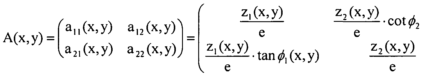
- magnification and motion matrix A (x, y) in the general case by
- the height functions z; i (x, y) and Z2 (x, y) of the displayed body merge into one another.
- the consideration is also possible with a suitable cylindrical lens grid, for example with a split screen or cylindrical lens grid, the unit cell through given with the gap or cylinder axis distance d, or with a fd O ⁇
- Aperture or lens array with W with d 2 , ß arbitrary.
- the pattern hereby generated for the print or embossed image to be created behind a lenticular screen W can be viewed not only with the slit diaphragm or cylindrical lens array with axis in the direction ⁇ , but also with a pinhole or lens array
- W , where d 2 , ß can be arbitrary.
- the arrangement has an orthoparallactic 3D effect, in which the body, in conventional observation (eye distance direction in x-axis), Direction) and when tilting the arrangement in the x-direction perpendicular to the x-axis moves.
- the body When rotated by 90 ° viewing (eye distance direction in y-direction) and tilting the arrangement in the y-direction, the body moves in the direction of ⁇ 2 to the x-axis.
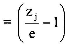
- a three-dimensional effect comes about here in normal observation (eye distance direction in x-direction) only by movement.
- j 1
- the A, matrix must then be chosen such that the upper left coefficient is equal to z ⁇ / e.
- f j (x, y) is the image function of the jth section, which is a brightness distribution (grayscale image), a color distribution (color image), a binary distribution (line drawing) or other image properties, such as transparency, reflectivity, density or the like , can specify.
- the transparency step function t, (x, y) is equal to 1 if the section j obscures underlying objects at the point (x, y) and is otherwise equal to 0.
- a woodcut or copper engraving 3D image is obtained, for example, if the sections f j , t j are described by several function values in the following way:
- magnification and motion matrix is given by. In all viewing directions, all eye distance directions, and when rotating the assembly, the depth remains unchanged.
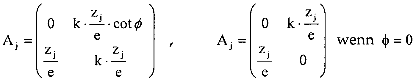
- a change factor k other than 0 is specified so that the magnification and motion matrix A j is the shape
- the depth impression of the illustrated body changes by the change factor k.
- a change factor k other than 0 and two angles ⁇ i and ⁇ 2 are given, so that the magnification and motion matrix A 1 is the
- the body moves in the direction ⁇ i to the x-axis, rotated by 90 ° (eye distance direction in y-direction) and tilting of the arrangement in y- direction.
- Direction is moving the body in the direction of ⁇ j> 2 to the x-axis and is stretched by the factor k in the depth dimension.
- the consideration is also possible with a suitable cylindrical lens grid, for example with a split screen or cylindrical lens grid, the unit cell through given with the gap or cylinder axis distance d.
- magnification and motion matrix Aj is the shape
- the vertical tilting tilts the body in the direction of ⁇ to the x-axis.
- the body shown always moves independently of the tilt direction in the direction ⁇ i to the x-axis.
- the image function m (x, y) is generally given by x.
- m (x, y) f
- the magnification term V (x, y) is generally a matrix
- V (x, y) Desired enlargement and movement behavior of the given body 15 describes and I is the unitary matrix.
- the magnification term is a scalar
- the vector (ci (x, y), C2 (x, y)) with 0 ⁇ c, (x, y), c 2 (x, y) ⁇ 1 gives the relative position of the center of the observation elements within the Cells of the motif image.
- the vector d2 (x, y)) Mito ⁇ d (x, y), d 2 (x, y) ⁇ 1 illustrates a shift of the cell boundaries in the motif image
- g (x, y) is a mask function for adjusting the visibility of the body.
- an angle constraint may be desirable when viewing the motif images, i.
- the illustrated three-dimensional image should not be visible from all directions or even be recognized only in a small solid angle range.
- Such an angle limitation may be particularly advantageous in combination with the alternating images described below, since the switching over from one motif to another is generally not simultaneously perceived by both eyes. This can lead to an unwanted double image being seen as a superimposition of adjacent image motifs during the switchover. If, however, the individual images are bordered by an edge of suitable width, such a visually undesirable overlay can be suppressed.
- mask functions can also define areas in which the three-dimensional image is not visible as a field constraint.
- the embodiments with adjacent images mentioned below can be described by such macroscopic mask functions.
- a masking function for image field limitation is given by 1 in areas where the 3D image should be visible
- the vector (d 1 (x, y) / d 2 (x, y)) was identical to zero, the cell boundaries were uniformly distributed over the entire area. In some embodiments, however, it may also be advantageous to shift the grid of the cells in the motif plane in a location-dependent manner in order to achieve special optical effects when changing the viewing direction.
- the image function m (x, y) is then in the form
- the vector (C 1 (x, y), C 2 (x, y)) may also be a function of the location.
- the image function m (x, y) is then in the form with 0 ⁇ c, (x, y), c 2 (x, y) ⁇ 1.
- the vector (d 1 (x, y) / d 2 (x, y)) not equal to zero and the motion matrix A (x, y) be location-dependent, so that for g ⁇ 1 the following general results:
- the vector (c; ⁇ (x, y), C2 (x, y)) describes the position of the cells in the motif image plane relative to the lens array W, wherein the raster of the lens centers can be considered as the reference point set. If the vector (C 1 (x, y), C 2 (x, y)) is a function of the location, this means that changes in (C 1 (x, y), C 2 (x, y)) are in one Changing the relative positioning between the cells in the scene image plane and the lenses, which leads to fluctuations in the periodicity of the motif picture elements.
- a location dependency of the vector (ci (x, y), C2 (x, y)) can be advantageously used if a film web is used which carries a lens embossing on the front side with a homogeneous homogeneous pattern W. If a modulo magnification arrangement with location-independent (C 1 (X 1), C 2 (x, y)) is imprinted on the rear side, it is left to chance, under which viewing angles one recognizes which features, if no exact registration between foreground and and backside embossing is possible.
- the three-dimensional image should not only be visible when viewed through a normal hole / lenticular grid, but also when viewed through a slit grid or cylindrical lens grid, wherein a three-dimensional image can be given in particular a non-periodically repeating individual image.
- the slit or cylindrical lens grid is described by:
- the matching matrix A with no magnification or distortion in the y-direction, is then:
- the matrix (A-1) in the relationship (A-1) W acts only on the first row of W, so that W can represent an infinitely long cylinder.
- Cell W fits, and is so large that the pattern to be created in the cells does not show complete coherent images.
- the pattern produced in this way can not be used only with the slit or cylindrical lens
- Array W view, but also with a pinhole
- the modulo magnification arrangement usually represents a single three-dimensional image (body) when viewed.
- the invention also encompasses configurations in which several three-dimensional images are displayed simultaneously or alternately.
- the three-dimensional images can in particular have different movement behavior when tilting the arrangement.
- three-dimensional images shown in alternation these can merge into one another in particular when tilting the arrangement.
- the different images can be independent of each other or content related to each other and represent, for example, a movement.
- the image function m (x, y) is then generally given by
- the vectors (c ⁇ (x, y), Ci2 (x, y)) with 0 ⁇ c ,, (x, y), c l2 (x, y) ⁇ 1 give the relative position of the center of the body for the body fi Viewing elements within the cells i of the motif image.
- the vectors (dn (x, y), di2 (x, y)) with O ⁇ d ,, (x, y), dl2 (x, y) ⁇ 1 represent respectively a shift of the cell boundaries in the motif image, and gi ( X / y) are mask functions for adjusting the visibility of the body fi.
- a simple example of multi-dimensional image (body) designs is a simple tilt image in which two three-dimensional bodies fi ( ⁇ , y) and f2 ( ⁇ , y) alternate as the security element is tilted in a similar manner. Under which viewing angles the change between the two bodies takes place is defined by the mask functions g ⁇ and g2. In order to prevent - even at observation with only one eye - both images can be seen simultaneously, the carriers of the functions g ⁇ and g2 are chosen disjointly.
- Master function F is the sum function. This results in the image function of the motif image m (x, y):
- the boundaries between the image areas in the motif image have been set at 0.5, so that the area sections belonging to the two images f and / 2 are the same size.
- the limits can be chosen arbitrarily in the general case.
- the location of the borders determines the solid angle ranges from which the two three-dimensional images can be seen.
- the images shown can also alternate in strips, for example by using the following mask functions: w u , w 21 ) + t 2 (w 12 , w 22 ) with 0 ⁇ t, ⁇ 0.5 and X 1
- a change of image information occurs when the security element is tilted along the direction indicated by the vector (w n , W 21 ), whereas tilting along the second vector (w 12 , W 22 ) results in no image change.
- the border was chosen at 0.5, ie the area of the motif image was divided into strips of equal width, which alternately contain the information of the two three-dimensional images.
- the boundary between the stripes can of course be arbitrarily set.
- modulo-morphing or modulo-cinema the various three-dimensional images are directly related, wherein in the case of modulo morphing, a starting image is transformed into a final image over a defined number of intermediate stages, and preferably simple sequences of motion are displayed in the modulo-cinema become.
- the three-dimensional images are in the elevation profile model through images
- the stripe width can be selected irregularly.
- linear tilting movement it is expedient to retrieve the image sequence by tilting along one direction (linear tilting movement), this is not absolutely necessary.
- the morphing or movement effects can also be played, for example, by meander-shaped or spiral-shaped tilting movements.
- the relative phase of each displayed image can be set individually, as expressed by the coefficients Ci j in the general formula for m (x, y).
- the relative phase controls in which viewing directions the motifs can be recognized. If, for the sake of simplicity, the unit function is selected for the mask functions gi, the cell boundaries in the motif image are not spatially dependent, and if the master function F is the sum function, then a series of superimposed three-dimensional images f ,:
- the use of the sum function as a master function corresponds to an addition of the gray, color, transparency or density values depending on the character of the image function f, the resulting image values typically being set to the maximum value when the maximum value range is exceeded.
- functions other than the sum function for the master function F for example an OR link, an exclusive-OR (XOR) link or the maximum function.
- functions other than the sum function for the master function F for example an OR link, an exclusive-OR (XOR) link or the maximum function.
- Other possibilities are to select the signal with the lowest value of function or, as above, to form the sum of all function values meeting at a certain point. If there is a maximum upper limit, for example the maximum exposure intensity of a laser exposure, then one can cut off the sum at this maximum value.
- All embodiments discussed in the context of this description can also be arranged side by side or in one another, for example as exchangeable images or as superimposed images.
- the boundaries between The image parts do not have to run in a straight line, but can be designed as desired. In particular, the boundaries may be chosen to represent the outlines of symbols or lettering, patterns, shapes of any kind, plants, animals or humans.
- the juxtaposed or nested image parts are considered in preferred embodiments with a uniform lens array.
- the magnification and movement matrix A of the different image parts may also differ, for example in order to allow specific movement effects of the individual magnified motifs. It may be advantageous to control the phase relationship between the image parts so that the enlarged motifs appear at a defined distance from each other.
- the microstructure plane can be calculated to render a three-dimensional object when viewed using a lenticular grid. This is basically based on the fact that the magnification factor is location-dependent, which means that the motive fragments in the different cells can have different sizes.
- This three-dimensional appearance can be enhanced by filling surfaces of different inclinations with blazed gratings whose parameters differ from each other.
- a blaze grating is defined by specifying the parameters azimuth angle ⁇ , period d and slope a.
- Fresnel structures for the visual appearance of a three-dimensional structure is the Reflection of the incident light at the surface of the structure crucial. Since the volume of the body is not critical to this effect, it can be eliminated using a simple algorithm. Round surfaces can be approximated by a large number of small flat surfaces.
- the period d of the saw teeth is sufficiently large in order to largely avoid the formation of colored diffraction effects.
- This development of the invention is thus based on combining two methods for generating three-dimensional structures with one another: location-dependent magnification factor and filling with Fresnel structures, blazed gratings or other optically active structures, such as sub-wavelength structures.
- each of the three sides is assigned a blaze grating, which differ in their azimuth angle.
- the azimuth angles are 0 °, 120 ° and 240 °.
- All surface areas representing side 1 of the pyramid are equipped with the blaze grating with azimuth 0 ° - regardless of their size defined by the location-dependent A matrix.
- pages 2 and 3 of the pyramid are used: they are filled with blaze gratings with azimuth angle 120 ° (page 2) or 240 ° (page 3).
- Another possibility is the use of light-absorbing structures. Instead of blaze grids, it is also possible to use structures that not only reflect light, but also absorb it to a greater extent. This is usually the case when the aspect ratio depth / width (period or quasi-period) is relatively high, for example 1/1 or 2/1 or higher.
- the period or quasi-period can range from sub-wavelength structures to microstructures - this also depends on the size of the cells. How dark a surface should appear can be regulated, for example, via the surface density of the structures or the aspect ratio. Surfaces of different inclinations can be assigned structures with different absorption properties.
- the lens elements or generally the viewing elements
- the lens elements need not be arranged in the form of a regular grid, but may be distributed at random in the space with different distances.
- the motif image designed for viewing with such a general viewing element arrangement can then no longer be described in the modulo notation, but is the following relationship
- prxY R 3 -> R 2
- pr ⁇ (x, y, z) (x, y) is the projection on XY plane
- X A ( ⁇ ) ⁇ [ n 0 otherwise and the lattice lattice W - ⁇ w,, w 2 , w 3 , ... ⁇ is given by any discrete subset of R 3 .
Abstract
Description


Claims


Priority Applications (4)
| Application Number | Priority Date | Filing Date | Title |
|---|---|---|---|
| EP08759341.4A EP2164711B1 (en) | 2007-06-25 | 2008-06-25 | Representation system |
| US12/665,843 US8878844B2 (en) | 2007-06-25 | 2008-06-25 | Representation system |
| AU2008267365A AU2008267365B2 (en) | 2007-06-25 | 2008-06-25 | Depiction Arrangement |
| CN2008800218663A CN101687427B (en) | 2007-06-25 | 2008-06-25 | Representation system |
Applications Claiming Priority (2)
| Application Number | Priority Date | Filing Date | Title |
|---|---|---|---|
| DE102007029204A DE102007029204A1 (en) | 2007-06-25 | 2007-06-25 | security element |
| DE102007029204.1 | 2007-06-25 |
Publications (1)
| Publication Number | Publication Date |
|---|---|
| WO2009000527A1 true WO2009000527A1 (en) | 2008-12-31 |
Family
ID=39929951
Family Applications (2)
| Application Number | Title | Priority Date | Filing Date |
|---|---|---|---|
| PCT/EP2008/005171 WO2009000527A1 (en) | 2007-06-25 | 2008-06-25 | Representation system |
| PCT/EP2008/005174 WO2009000530A2 (en) | 2007-06-25 | 2008-06-25 | Security element having a magnified, three-dimensional moiré image |
Family Applications After (1)
| Application Number | Title | Priority Date | Filing Date |
|---|---|---|---|
| PCT/EP2008/005174 WO2009000530A2 (en) | 2007-06-25 | 2008-06-25 | Security element having a magnified, three-dimensional moiré image |
Country Status (7)
| Country | Link |
|---|---|
| US (2) | US8400495B2 (en) |
| EP (2) | EP2164711B1 (en) |
| CN (2) | CN101711203B (en) |
| AU (2) | AU2008267365B2 (en) |
| DE (1) | DE102007029204A1 (en) |
| RU (2) | RU2466875C2 (en) |
| WO (2) | WO2009000527A1 (en) |
Cited By (41)
| Publication number | Priority date | Publication date | Assignee | Title |
|---|---|---|---|---|
| DE102008053099A1 (en) | 2008-10-24 | 2010-04-29 | Giesecke & Devrient Gmbh | Security element with pressure-sensitive appearance |
| DE102008062475A1 (en) | 2008-12-16 | 2010-06-17 | Giesecke & Devrient Gmbh | Security element and security paper |
| WO2011015384A1 (en) | 2009-08-04 | 2011-02-10 | Giesecke & Devrient Gmbh | Security arrangement |
| WO2011066991A2 (en) | 2009-12-04 | 2011-06-09 | Giesecke & Devrient Gmbh | Security element, value document comprising such a security element and method for producing such a security element |
| WO2011138039A1 (en) | 2010-05-07 | 2011-11-10 | Giesecke & Devrient Gmbh | Method for producing a mictostructure on a carrier |
| WO2011163298A1 (en) | 2010-06-22 | 2011-12-29 | Visual Physics, Llc | An optical system demonstrating improved resistance to optically degrading external effects |
| DE102010025775A1 (en) | 2010-07-01 | 2012-01-05 | Giesecke & Devrient Gmbh | Security element and value document with such a security element |
| DE102010055689A1 (en) | 2010-12-22 | 2012-06-28 | Giesecke & Devrient Gmbh | Micro-optical viewing arrangement |
| DE102011010127A1 (en) | 2011-02-02 | 2012-08-02 | Giesecke & Devrient Gmbh | Authenticity assurance of value documents by means of photochromic dyes |
| DE102011114750A1 (en) | 2011-09-29 | 2013-04-04 | Giesecke & Devrient Gmbh | Process for producing a microstructure support |
| DE102011115125A1 (en) | 2011-10-07 | 2013-04-11 | Giesecke & Devrient Gmbh | Method for producing micro-optical display assembly for displaying multicolor subject, involves providing carrier material with main surface and with another main surface, where former main surface has focusing element grid |
| US8490879B2 (en) | 2008-07-09 | 2013-07-23 | Giesecke & Devrient Gmbh | Security element |
| US8526085B2 (en) | 2007-08-22 | 2013-09-03 | Giesecke & Devrient Gmbh | Grid image |
| US8534710B2 (en) | 2008-07-02 | 2013-09-17 | Giesecke & Devrient Gmbh | Security element and method for manufacturing the same |
| EP2660067A1 (en) | 2012-05-04 | 2013-11-06 | Giesecke & Devrient GmbH | Security documents having a protective coating and a method for their preparation |
| US8603615B2 (en) | 2007-07-23 | 2013-12-10 | Giesecke & Devrient Gmbh | Security element |
| US8702906B2 (en) | 2006-12-12 | 2014-04-22 | Giesecke & Devrient Gmbh | Dewatering screen and method for manufacturing the same |
| US8773763B2 (en) | 2003-11-21 | 2014-07-08 | Visual Physics, Llc | Tamper indicating optical security device |
| US8878844B2 (en) | 2007-06-25 | 2014-11-04 | Giesecke & Devrient Gmbh | Representation system |
| US8906184B2 (en) | 2008-04-02 | 2014-12-09 | Giesecke & Devrient Gmbh | Method for producing a micro-optical display arrangement |
| US8998264B2 (en) | 2009-07-31 | 2015-04-07 | Giesecke & Devrient Gmbh | Identification document having a personalized visual identifier and method for production thereof |
| US9004540B2 (en) | 2007-12-21 | 2015-04-14 | Giesecke & Devrient Gmbh | Security element |
| US9297941B2 (en) | 2011-07-21 | 2016-03-29 | Giesecke & Deverient Gmbh | Optically variable element, in particular security element |
| US9308774B2 (en) | 2008-06-12 | 2016-04-12 | Giesecke & Devrient Gmbh | Security element comprising a screened layer |
| US9333787B2 (en) | 2011-01-28 | 2016-05-10 | Visual Physics, Llc | Laser marked device |
| US9399366B2 (en) | 2008-06-23 | 2016-07-26 | Giesecke & Devrient Gmbh | Security element |
| US9415622B2 (en) | 2008-06-12 | 2016-08-16 | Giesecke & Devrient Gmbh | Security element with optically variable element |
| US9827802B2 (en) | 2009-12-04 | 2017-11-28 | Giesecke+Devrient Currency Technology Gmbh | Security element, value document comprising such a security element, and method for producing such a security element |
| US9873281B2 (en) | 2013-06-13 | 2018-01-23 | Visual Physics, Llc | Single layer image projection film |
| US10173405B2 (en) | 2012-08-17 | 2019-01-08 | Visual Physics, Llc | Process for transferring microstructures to a final substrate |
| US10173453B2 (en) | 2013-03-15 | 2019-01-08 | Visual Physics, Llc | Optical security device |
| US10189292B2 (en) | 2015-02-11 | 2019-01-29 | Crane & Co., Inc. | Method for the surface application of a security device to a substrate |
| US10195890B2 (en) | 2014-09-16 | 2019-02-05 | Crane Security Technologies, Inc. | Secure lens layer |
| EP3319813B1 (en) | 2015-07-10 | 2019-08-28 | De La Rue International Limited | Security documents and security devices and method of their manufaturing |
| US10434812B2 (en) | 2014-03-27 | 2019-10-08 | Visual Physics, Llc | Optical device that produces flicker-like optical effects |
| US10525759B2 (en) | 2005-12-21 | 2020-01-07 | Giesecke+Devrient Currency Technology Gmbh.. | Visually variable security element and method for production thereof |
| US10625532B2 (en) | 2007-06-25 | 2020-04-21 | Giesecke+Devrient Currency Technology Gmbh | Security element |
| US10766292B2 (en) | 2014-03-27 | 2020-09-08 | Crane & Co., Inc. | Optical device that provides flicker-like optical effects |
| US10800203B2 (en) | 2014-07-17 | 2020-10-13 | Visual Physics, Llc | Polymeric sheet material for use in making polymeric security documents such as banknotes |
| US10890692B2 (en) | 2011-08-19 | 2021-01-12 | Visual Physics, Llc | Optionally transferable optical system with a reduced thickness |
| US11590791B2 (en) | 2017-02-10 | 2023-02-28 | Crane & Co., Inc. | Machine-readable optical security device |
Families Citing this family (52)
| Publication number | Priority date | Publication date | Assignee | Title |
|---|---|---|---|---|
| DE102005022018A1 (en) * | 2005-05-12 | 2006-11-16 | Giesecke & Devrient Gmbh | Security paper and process for its production |
| DE102007061827A1 (en) * | 2007-12-20 | 2009-06-25 | Giesecke & Devrient Gmbh | Security element and method for its production |
| DE102007061828A1 (en) * | 2007-12-20 | 2009-06-25 | Giesecke & Devrient Gmbh | Security element and method for its production |
| DE102007062089A1 (en) | 2007-12-21 | 2009-07-02 | Giesecke & Devrient Gmbh | Method for creating a microstructure |
| DE102008008685A1 (en) * | 2008-02-12 | 2009-08-13 | Giesecke & Devrient Gmbh | Security element and method for its production |
| DE102008009296A1 (en) * | 2008-02-15 | 2009-08-20 | Giesecke & Devrient Gmbh | Security element and method for its production |
| DE102008013167A1 (en) | 2008-03-07 | 2009-09-10 | Giesecke & Devrient Gmbh | Security element and method for its production |
| DE102008046511A1 (en) | 2008-09-10 | 2010-03-11 | Giesecke & Devrient Gmbh | representation arrangement |
| EP2233314A1 (en) * | 2009-03-26 | 2010-09-29 | CSEM Centre Suisse d'Electronique et de Microtechnique SA - Recherche et Développement | Authentication item and system for packaged articles and method for the manufacturing of the authentication item |
| DE102009033221A1 (en) * | 2009-07-14 | 2011-01-27 | Human Bios Gmbh | Security element for marking or identification of objects and living beings |
| DE102009041583A1 (en) | 2009-09-15 | 2011-03-17 | Giesecke & Devrient Gmbh | Thin-film element with interference layer structure |
| DE102009042022A1 (en) | 2009-09-21 | 2011-03-24 | Giesecke & Devrient Gmbh | Elongated security element with machine-readable magnetic areas |
| GB201003397D0 (en) | 2010-03-01 | 2010-04-14 | Rue De Int Ltd | Moire magnification security device |
| DE112011100983T5 (en) * | 2010-03-24 | 2013-04-11 | Securency International Pty Ltd. | Security document with integrated security device and manufacturing process |
| DE102010048262A1 (en) | 2010-10-12 | 2012-04-12 | Giesecke & Devrient Gmbh | presentation element |
| DE102010048772A1 (en) * | 2010-10-13 | 2012-04-19 | Bundesdruckerei Gmbh | A method of producing a security document having a viewing angle dependent security feature and security document |
| KR20120053430A (en) * | 2010-11-17 | 2012-05-25 | 삼성전자주식회사 | Device and method for providing image effect in wireless terminal |
| CH701875A3 (en) | 2011-01-18 | 2011-11-30 | Trueb Ag | Method for producing a multilayer data carrier and data carrier produced by this method. |
| DE102011101635A1 (en) * | 2011-05-16 | 2012-11-22 | Giesecke & Devrient Gmbh | Two-dimensionally periodic, color-filtering grid |
| JP2014528850A (en) | 2011-06-28 | 2014-10-30 | ビジュアル フィジクス エルエルシー | Low curl or no curl optical film-paper laminate |
| DE102011112554A1 (en) * | 2011-09-06 | 2013-03-07 | Giesecke & Devrient Gmbh | Method for producing a security paper and microlens thread |
| RU2605372C9 (en) | 2011-09-26 | 2017-05-24 | Крейн Секьюрити Текнолоджис, Инк. | Method for producing composite web and security devices made from composite web |
| AU2012325669A1 (en) * | 2011-10-19 | 2014-05-29 | Ccl Secure Pty Ltd | Security device |
| AU2013251640C1 (en) | 2012-04-25 | 2018-01-25 | Visual Physics, Llc | Security device for projecting a collection of synthetic images |
| WO2013188518A1 (en) | 2012-06-13 | 2013-12-19 | Visual Physics, Llc | Micro-optic material with improved abrasion resistance |
| JP6061552B2 (en) * | 2012-08-23 | 2017-01-18 | キヤノン株式会社 | Head-mounted image display device |
| US9132690B2 (en) * | 2012-09-05 | 2015-09-15 | Lumenco, Llc | Pixel mapping, arranging, and imaging for round and square-based micro lens arrays to achieve full volume 3D and multi-directional motion |
| NL2010045C2 (en) | 2012-12-21 | 2014-06-24 | Morpho B V | Identity document comprising a ghost image based on a two- dimensional image. |
| RU2510689C1 (en) * | 2013-04-04 | 2014-04-10 | Федеральное Государственное Унитарное Предприятие "Гознак" (Фгуп "Гознак") | Multilayer polymer material with raster structure |
| RU2528646C1 (en) | 2013-06-28 | 2014-09-20 | Федеральное Государственное Унитарное Предприятие "Гознак" (Фгуп "Гознак") | Multilayer article having security element on surface of paper or polymer carrier, article authentication method |
| RU2528252C1 (en) | 2013-07-08 | 2014-09-10 | Федеральное Государственное Унитарное Предприятие "Гознак" (Фгуп "Гознак") | Multilayer document on paper or polymer substrate and method of determining its authenticity |
| CN103862997A (en) * | 2014-01-26 | 2014-06-18 | 张靖 | Decorating part with dynamic image effect |
| EP2908341B1 (en) * | 2014-02-18 | 2018-07-11 | ams AG | Semiconductor device with surface integrated focusing element |
| RU2573879C2 (en) * | 2014-03-18 | 2016-01-27 | Федеральное Государственное Унитарное Предприятие "Гознак" (Фгуп "Гознак") | Counterfeit-protected multilayer data medium |
| CN104118236B (en) * | 2014-07-10 | 2016-08-24 | 中钞特种防伪科技有限公司 | The micro-reflecting element array optical Security element of a kind of focusing and valuables |
| CN104191860B (en) * | 2014-08-27 | 2016-06-22 | 苏州大学 | Colored dynamic solid moir é pattern thin film based on micro-printing and preparation method thereof |
| RU2596949C2 (en) * | 2014-09-18 | 2016-09-10 | Общество с ограниченной ответственностью "Полиграф-защита СПб" | Contact-droplet hgh printing method micro lenses on a flat information carrier and protective element on a flat carrier information |
| RU2596948C2 (en) * | 2014-09-18 | 2016-09-10 | Общество с ограниченной ответственностью "Полиграф-защита СПб" | Raster-moire optical system |
| CN104773003B (en) * | 2015-04-17 | 2019-12-10 | 中钞油墨有限公司 | Printing stock printed with pattern for enhancing dynamic optical variation anti-counterfeiting effect and manufacturing method thereof |
| GB2549215B (en) * | 2015-06-10 | 2018-07-25 | De La Rue Int Ltd | Security devices and methods of manufacture thereof |
| DE102015218829B4 (en) | 2015-09-30 | 2018-08-16 | Bayerische Motoren Werke Aktiengesellschaft | An image forming apparatus and method of making an array of imaging elements |
| US10189294B2 (en) | 2015-12-03 | 2019-01-29 | Lumenco, Llc | Arrays of individually oriented micro mirrors for use in imaging security devices for currency and brand authentication |
| DE102016007784A1 (en) * | 2016-06-24 | 2017-12-28 | Giesecke+Devrient Currency Technology Gmbh | Optically variable security element |
| GB201612290D0 (en) * | 2016-07-15 | 2016-08-31 | La Rue Int De Ltd | Methods of manufacturing a secuirty device |
| DE102016221918A1 (en) | 2016-11-09 | 2018-05-09 | Bayerische Motoren Werke Aktiengesellschaft | Lighting device, in particular for a motor vehicle |
| EA030058B1 (en) * | 2017-03-15 | 2018-06-29 | Общество С Ограниченной Ответственностью "Центр Компьютерной Голографии" | Microoptical system for formation of visual images with kinematic motion effects |
| DE102017004585A1 (en) * | 2017-05-12 | 2018-11-15 | Giesecke+Devrient Currency Technology Gmbh | Security element with micro-reflectors |
| JP6804389B2 (en) * | 2017-05-30 | 2020-12-23 | 株式会社ニューフレアテクノロジー | Drawing device and drawing method |
| DE102017006421A1 (en) * | 2017-07-07 | 2019-01-10 | Giesecke+Devrient Currency Technology Gmbh | Optically variable safety arrangement |
| RU188364U1 (en) * | 2018-08-01 | 2019-04-09 | Общество с Ограниченной Ответственностью (ООО) "МИДИ ПРИНТ" | STICKER |
| DE102018010078A1 (en) * | 2018-12-20 | 2020-06-25 | Giesecke+Devrient Currency Technology Gmbh | Optically variable security element |
| CN110133847B (en) * | 2019-04-29 | 2020-10-16 | 中国科学院光电技术研究所 | Design method for non-array dynamic display anti-counterfeiting pattern based on microstructure |
Citations (4)
| Publication number | Priority date | Publication date | Assignee | Title |
|---|---|---|---|---|
| US5712731A (en) * | 1993-05-11 | 1998-01-27 | Thomas De La Rue Limited | Security device for security documents such as bank notes and credit cards |
| GB2362493A (en) * | 2000-04-04 | 2001-11-21 | Floating Images Ltd | Display device with apparent depth of field |
| WO2006029745A1 (en) * | 2004-09-15 | 2006-03-23 | Ovd Kinegram Ag | Security document with transparent windows |
| WO2006087138A1 (en) * | 2005-02-18 | 2006-08-24 | Giesecke & Devrient Gmbh | Security element and method for the production thereof |
Family Cites Families (88)
| Publication number | Priority date | Publication date | Assignee | Title |
|---|---|---|---|---|
| US1475430A (en) * | 1922-02-27 | 1923-11-27 | Curwen John Spedding | Advertising device or toy |
| EP0064067B2 (en) | 1980-11-05 | 2002-03-27 | McGREW, Stephen Paul | Method for generating a diffractive graphical composition |
| ATE84751T1 (en) * | 1985-10-15 | 1993-02-15 | Gao Ges Automation Org | MEDIA WITH AN OPTICAL MARK OF AUTHENTICATION, METHODS OF MAKING AND VERIFYING THE MEDIA. |
| DE3602563C1 (en) | 1986-01-29 | 1987-04-16 | Deutsche Bundesbank | Security paper with optically active structures generating a moiré effect |
| DE3609090A1 (en) | 1986-03-18 | 1987-09-24 | Gao Ges Automation Org | SECURITY PAPER WITH SECURED THREAD STORED IN IT AND METHOD FOR THE PRODUCTION THEREOF |
| EP0330733B1 (en) | 1988-03-04 | 1994-01-26 | GAO Gesellschaft für Automation und Organisation mbH | Thread- or strip-like security element to be included in a security document, and a method of manufacturing same |
| JP2761861B2 (en) * | 1996-02-06 | 1998-06-04 | 明和グラビア株式会社 | Decorative sheet |
| JP3338860B2 (en) | 1996-07-17 | 2002-10-28 | ヤマックス株式会社 | Decorative pattern |
| US5772250A (en) | 1997-04-11 | 1998-06-30 | Eastman Kodak Company | Copy restrictive color-reversal documents |
| DE19739193B4 (en) | 1997-09-08 | 2006-08-03 | Giesecke & Devrient Gmbh | Method for producing security films for securities |
| JP3131771B2 (en) | 1997-12-26 | 2001-02-05 | 明和グラビア株式会社 | Decorative sheet with three-dimensional effect |
| US6483644B1 (en) * | 1998-08-07 | 2002-11-19 | Phil Gottfried | Integral image, method and device |
| JP3505617B2 (en) | 1999-06-09 | 2004-03-08 | ヤマックス株式会社 | Virtual image appearance decoration |
| DE19949542C2 (en) | 1999-10-14 | 2002-07-11 | Orga Kartensysteme Gmbh | Process for the production of micro-writing on data carriers, in particular plastic cards |
| US7068434B2 (en) | 2000-02-22 | 2006-06-27 | 3M Innovative Properties Company | Sheeting with composite image that floats |
| US6288842B1 (en) * | 2000-02-22 | 2001-09-11 | 3M Innovative Properties | Sheeting with composite image that floats |
| US6450540B1 (en) * | 2000-11-15 | 2002-09-17 | Technology Tree Co., Ltd | Printed matter displaying various colors according to view angle |
| JP2003039583A (en) * | 2001-07-27 | 2003-02-13 | Meiwa Gravure Co Ltd | Decorative sheet |
| JP2003120500A (en) | 2001-10-10 | 2003-04-23 | Maeda Seikan Kk | Wind mill with vertical axis having guide plate for small power |
| US7751608B2 (en) * | 2004-06-30 | 2010-07-06 | Ecole Polytechnique Federale De Lausanne (Epfl) | Model-based synthesis of band moire images for authenticating security documents and valuable products |
| US7194105B2 (en) | 2002-10-16 | 2007-03-20 | Hersch Roger D | Authentication of documents and articles by moiré patterns |
| DE10254500B4 (en) * | 2002-11-22 | 2006-03-16 | Ovd Kinegram Ag | Optically variable element and its use |
| DE10325146A1 (en) * | 2003-05-30 | 2004-12-16 | X3D Technologies Gmbh | Method and arrangement for spatial representation |
| EP1695121B1 (en) | 2003-11-21 | 2014-06-04 | Visual Physics, LLC | Micro-optic security and image presentation system |
| DE102004007379B3 (en) | 2004-02-16 | 2005-09-01 | Ovd Kinegram Ag | Valuable object with moiré pattern |
| WO2005106601A2 (en) | 2004-04-30 | 2005-11-10 | De La Rue International Limited | Arrays of microlenses and arrays of microimages on transparent security substrates |
| DE102004021247A1 (en) * | 2004-04-30 | 2005-11-24 | Giesecke & Devrient Gmbh | Security element and method for its production |
| DE102004021246A1 (en) | 2004-04-30 | 2005-11-24 | Giesecke & Devrient Gmbh | Security element and method for its production |
| DE102004039355A1 (en) | 2004-08-12 | 2006-02-23 | Giesecke & Devrient Gmbh | Security element and method for its production |
| EP2123471B1 (en) * | 2004-04-30 | 2015-07-08 | Giesecke & Devrient GmbH | Safety element and method for its production |
| US7808605B2 (en) | 2004-04-30 | 2010-10-05 | Giesecke & Devrient Gmbh | Sheeting and methods for the production thereof |
| DE102004022079A1 (en) | 2004-05-05 | 2005-11-24 | Giesecke & Devrient Gmbh | Value document with serial number |
| DE102004022080A1 (en) | 2004-05-05 | 2005-11-24 | Giesecke & Devrient Gmbh | Value document with visually recognizable markings |
| DE102004031879B4 (en) * | 2004-06-30 | 2017-11-02 | Ovd Kinegram Ag | Security document for RF identification |
| DE102004035979A1 (en) * | 2004-07-14 | 2006-02-02 | Giesecke & Devrient Gmbh | Security element and method for its production |
| DE102004038542A1 (en) * | 2004-08-06 | 2006-02-23 | Giesecke & Devrient Gmbh | Data carrier with security element and method for its production |
| CA2577208C (en) | 2004-08-12 | 2015-10-13 | Giesecke & Devrient Gmbh | Security element having a substrate |
| DE102004049118A1 (en) | 2004-10-07 | 2006-04-13 | Giesecke & Devrient Gmbh | Security element and method for its production |
| DE102004056553B4 (en) | 2004-11-23 | 2013-03-14 | Giesecke & Devrient Gmbh | Security arrangement for security documents and method for producing the security documents |
| DE102004059798A1 (en) * | 2004-12-10 | 2006-06-29 | Ovd Kinegram Ag | Optically variable element with electrically active layer |
| DE102004063217A1 (en) * | 2004-12-29 | 2006-07-13 | Giesecke & Devrient Gmbh | Security feature for value documents |
| DE102005045566A1 (en) | 2005-03-23 | 2006-09-28 | Giesecke & Devrient Gmbh | Multi-layer security paper |
| DE102005022018A1 (en) | 2005-05-12 | 2006-11-16 | Giesecke & Devrient Gmbh | Security paper and process for its production |
| EP1893074B2 (en) * | 2005-05-18 | 2017-06-14 | Visual Physics, LLC | Image presentation and micro-optic security system |
| DE102005025095A1 (en) * | 2005-06-01 | 2006-12-07 | Giesecke & Devrient Gmbh | Data carrier and method for its production |
| DE102005032815A1 (en) | 2005-07-12 | 2007-01-18 | Giesecke & Devrient Gmbh | Method for producing a security paper, paper screen and forming element for paper screen |
| EP1905613A4 (en) * | 2005-07-12 | 2013-08-21 | Grapac Japan Co Inc | Stereoscopic sheet structure |
| DE102005032997A1 (en) * | 2005-07-14 | 2007-01-18 | Giesecke & Devrient Gmbh | Lattice image and method for its production |
| US7487915B2 (en) | 2005-09-09 | 2009-02-10 | Graphic Security Systems Corporation | Reflective decoders for use in decoding optically encoded images |
| DE102005052562A1 (en) | 2005-11-02 | 2007-05-03 | Giesecke & Devrient Gmbh | Method for production of safety element with optically variable structure, involves providing substrate with marking structure with many flat markings and relief structure with many reflex relief elements |
| DE102005061749A1 (en) | 2005-12-21 | 2007-07-05 | Giesecke & Devrient Gmbh | Optically variable security element for making valuable objects safe has an achromatic reflecting micro-structure taking the form of a mosaic made from achromatic reflecting mosaic elements |
| DE102005062132A1 (en) | 2005-12-23 | 2007-07-05 | Giesecke & Devrient Gmbh | Security unit e.g. seal, for e.g. valuable document, has motive image with planar periodic arrangement of micro motive units, and periodic arrangement of lens for moire magnified observation of motive units |
| DE102006005000B4 (en) | 2006-02-01 | 2016-05-04 | Ovd Kinegram Ag | Multi-layer body with microlens arrangement |
| DE102006006501A1 (en) | 2006-02-13 | 2007-08-16 | Giesecke & Devrient Gmbh | Security element with an optically variable structure |
| DE102006015023A1 (en) | 2006-03-31 | 2007-10-04 | Giesecke & Devrient Gmbh | Security element for security papers, value documents, has relief structure, which is formed on basis of cholesteric, liquid crystalline polymer material and top layer contains reflecting or high-refracting layer |
| DE102006023084B4 (en) | 2006-05-16 | 2019-07-18 | Leonhard Kurz Stiftung & Co. Kg | Value document with security element |
| DE102006029536B4 (en) | 2006-06-26 | 2011-05-05 | Ovd Kinegram Ag | Multi-layer body with microlenses and process for its preparation |
| DE102006029852A1 (en) | 2006-06-27 | 2008-01-03 | Giesecke & Devrient Gmbh | Method of applying a microstructure, mold and microstructured article |
| DE102006029850A1 (en) * | 2006-06-27 | 2008-01-03 | Giesecke & Devrient Gmbh | security element |
| MX2009000185A (en) | 2006-06-28 | 2009-07-03 | Visual Physics Llc | Micro-optic security and image presentation system. |
| DE102006039305A1 (en) * | 2006-07-21 | 2008-01-24 | Giesecke & Devrient Gmbh | Security thread with optically variable security feature |
| DE102006050047A1 (en) | 2006-10-24 | 2008-04-30 | Giesecke & Devrient Gmbh | Transparent security element for security papers, data carrier, particularly valuable documents such as bank note, identification card and for falsification of goods, has transparent substrate and marking layer applied on substrate |
| DE102006055680A1 (en) | 2006-11-23 | 2008-05-29 | Giesecke & Devrient Gmbh | Security element with metallization |
| DE102006058513A1 (en) * | 2006-12-12 | 2008-06-19 | Giesecke & Devrient Gmbh | Drainage screen and process for its production |
| DE102007005414A1 (en) | 2007-01-30 | 2008-08-07 | Ovd Kinegram Ag | Security element for securing value documents |
| DE102007029203A1 (en) | 2007-06-25 | 2009-01-08 | Giesecke & Devrient Gmbh | security element |
| DE102007029204A1 (en) | 2007-06-25 | 2009-01-08 | Giesecke & Devrient Gmbh | security element |
| DE102007034716A1 (en) | 2007-07-23 | 2009-01-29 | Giesecke & Devrient Gmbh | security element |
| DE102007039591A1 (en) * | 2007-08-22 | 2009-02-26 | Giesecke & Devrient Gmbh | grid image |
| CA2702654C (en) * | 2007-09-03 | 2017-03-14 | National Printing Bureau, Incorporated Administrative Agency | Anti-counterfeit printed matter |
| DE102007061827A1 (en) | 2007-12-20 | 2009-06-25 | Giesecke & Devrient Gmbh | Security element and method for its production |
| DE102007061828A1 (en) | 2007-12-20 | 2009-06-25 | Giesecke & Devrient Gmbh | Security element and method for its production |
| DE102007061979A1 (en) | 2007-12-21 | 2009-06-25 | Giesecke & Devrient Gmbh | security element |
| DE102007062089A1 (en) | 2007-12-21 | 2009-07-02 | Giesecke & Devrient Gmbh | Method for creating a microstructure |
| CN101945797B (en) * | 2008-02-12 | 2013-01-30 | 株式会社捷太格特 | Vehicle steering device |
| DE102008008685A1 (en) | 2008-02-12 | 2009-08-13 | Giesecke & Devrient Gmbh | Security element and method for its production |
| DE102008009296A1 (en) | 2008-02-15 | 2009-08-20 | Giesecke & Devrient Gmbh | Security element and method for its production |
| DE102008013167A1 (en) * | 2008-03-07 | 2009-09-10 | Giesecke & Devrient Gmbh | Security element and method for its production |
| DE102008016795A1 (en) | 2008-04-02 | 2009-10-08 | Giesecke & Devrient Gmbh | Method for producing a micro-optical moiré magnification arrangement |
| DE102008028187A1 (en) | 2008-06-12 | 2009-12-17 | Giesecke & Devrient Gmbh | Security element with optically variable element. |
| DE102008027952A1 (en) | 2008-06-12 | 2009-12-17 | Giesecke & Devrient Gmbh | Security element with screened layer of raster elements |
| DE102008029638A1 (en) | 2008-06-23 | 2009-12-24 | Giesecke & Devrient Gmbh | security element |
| DE102008031325A1 (en) | 2008-07-02 | 2010-01-07 | Giesecke & Devrient Gmbh | Security element and method for its production |
| DE102008032224A1 (en) | 2008-07-09 | 2010-01-14 | Giesecke & Devrient Gmbh | security element |
| DE102008046511A1 (en) | 2008-09-10 | 2010-03-11 | Giesecke & Devrient Gmbh | representation arrangement |
| DE102009035413A1 (en) | 2009-07-31 | 2011-02-03 | Giesecke & Devrient Gmbh | Identification document with a personalized visual identification and method for its production |
| DE102009041583A1 (en) | 2009-09-15 | 2011-03-17 | Giesecke & Devrient Gmbh | Thin-film element with interference layer structure |
| DE102009042022A1 (en) | 2009-09-21 | 2011-03-24 | Giesecke & Devrient Gmbh | Elongated security element with machine-readable magnetic areas |
-
2007
- 2007-06-25 DE DE102007029204A patent/DE102007029204A1/en not_active Withdrawn
-
2008
- 2008-06-25 WO PCT/EP2008/005171 patent/WO2009000527A1/en active Search and Examination
- 2008-06-25 CN CN2008800218678A patent/CN101711203B/en active Active
- 2008-06-25 AU AU2008267365A patent/AU2008267365B2/en active Active
- 2008-06-25 EP EP08759341.4A patent/EP2164711B1/en active Active
- 2008-06-25 CN CN2008800218663A patent/CN101687427B/en active Active
- 2008-06-25 RU RU2010101424/12A patent/RU2466875C2/en active
- 2008-06-25 WO PCT/EP2008/005174 patent/WO2009000530A2/en active Application Filing
- 2008-06-25 AU AU2008267368A patent/AU2008267368B2/en active Active
- 2008-06-25 EP EP08759342.2A patent/EP2164713B1/en active Active
- 2008-06-25 US US12/665,834 patent/US8400495B2/en active Active
- 2008-06-25 RU RU2010101423/12A patent/RU2466030C2/en active
- 2008-06-25 US US12/665,843 patent/US8878844B2/en active Active
Patent Citations (4)
| Publication number | Priority date | Publication date | Assignee | Title |
|---|---|---|---|---|
| US5712731A (en) * | 1993-05-11 | 1998-01-27 | Thomas De La Rue Limited | Security device for security documents such as bank notes and credit cards |
| GB2362493A (en) * | 2000-04-04 | 2001-11-21 | Floating Images Ltd | Display device with apparent depth of field |
| WO2006029745A1 (en) * | 2004-09-15 | 2006-03-23 | Ovd Kinegram Ag | Security document with transparent windows |
| WO2006087138A1 (en) * | 2005-02-18 | 2006-08-24 | Giesecke & Devrient Gmbh | Security element and method for the production thereof |
Cited By (59)
| Publication number | Priority date | Publication date | Assignee | Title |
|---|---|---|---|---|
| US8867134B2 (en) | 2003-11-21 | 2014-10-21 | Visual Physics, Llc | Optical system demonstrating improved resistance to optically degrading external effects |
| US8773763B2 (en) | 2003-11-21 | 2014-07-08 | Visual Physics, Llc | Tamper indicating optical security device |
| US10525759B2 (en) | 2005-12-21 | 2020-01-07 | Giesecke+Devrient Currency Technology Gmbh.. | Visually variable security element and method for production thereof |
| US8702906B2 (en) | 2006-12-12 | 2014-04-22 | Giesecke & Devrient Gmbh | Dewatering screen and method for manufacturing the same |
| US8878844B2 (en) | 2007-06-25 | 2014-11-04 | Giesecke & Devrient Gmbh | Representation system |
| US10625532B2 (en) | 2007-06-25 | 2020-04-21 | Giesecke+Devrient Currency Technology Gmbh | Security element |
| US8603615B2 (en) | 2007-07-23 | 2013-12-10 | Giesecke & Devrient Gmbh | Security element |
| US8526085B2 (en) | 2007-08-22 | 2013-09-03 | Giesecke & Devrient Gmbh | Grid image |
| US9004540B2 (en) | 2007-12-21 | 2015-04-14 | Giesecke & Devrient Gmbh | Security element |
| US8906184B2 (en) | 2008-04-02 | 2014-12-09 | Giesecke & Devrient Gmbh | Method for producing a micro-optical display arrangement |
| US9308774B2 (en) | 2008-06-12 | 2016-04-12 | Giesecke & Devrient Gmbh | Security element comprising a screened layer |
| US9415622B2 (en) | 2008-06-12 | 2016-08-16 | Giesecke & Devrient Gmbh | Security element with optically variable element |
| US9399366B2 (en) | 2008-06-23 | 2016-07-26 | Giesecke & Devrient Gmbh | Security element |
| US8534710B2 (en) | 2008-07-02 | 2013-09-17 | Giesecke & Devrient Gmbh | Security element and method for manufacturing the same |
| US8490879B2 (en) | 2008-07-09 | 2013-07-23 | Giesecke & Devrient Gmbh | Security element |
| DE102008053099A1 (en) | 2008-10-24 | 2010-04-29 | Giesecke & Devrient Gmbh | Security element with pressure-sensitive appearance |
| DE102008062475A1 (en) | 2008-12-16 | 2010-06-17 | Giesecke & Devrient Gmbh | Security element and security paper |
| US8998264B2 (en) | 2009-07-31 | 2015-04-07 | Giesecke & Devrient Gmbh | Identification document having a personalized visual identifier and method for production thereof |
| WO2011015384A1 (en) | 2009-08-04 | 2011-02-10 | Giesecke & Devrient Gmbh | Security arrangement |
| EP3851290A1 (en) | 2009-12-04 | 2021-07-21 | Giesecke+Devrient Currency Technology GmbH | Security element, valuable document comprising such a security element and method for producing such a security element |
| US9827802B2 (en) | 2009-12-04 | 2017-11-28 | Giesecke+Devrient Currency Technology Gmbh | Security element, value document comprising such a security element, and method for producing such a security element |
| EP3216620A1 (en) | 2009-12-04 | 2017-09-13 | Giesecke+Devrient Currency Technology GmbH | Security element, valuable document comprising such a security element and method for producing such a security element |
| US9176266B2 (en) | 2009-12-04 | 2015-11-03 | Giesecke & Devrient Gmbh | Security element, value document comprising such a security element and method for producing such a security element |
| US10525758B2 (en) | 2009-12-04 | 2020-01-07 | Giesecke+Devrient Currency Technology Gmbh | Security element, value document comprising such a security element, and method for producing such a security element |
| WO2011066991A2 (en) | 2009-12-04 | 2011-06-09 | Giesecke & Devrient Gmbh | Security element, value document comprising such a security element and method for producing such a security element |
| DE102010019766A1 (en) | 2010-05-07 | 2011-11-10 | Giesecke & Devrient Gmbh | Method for producing a microstructure on a support |
| US8964296B2 (en) | 2010-05-07 | 2015-02-24 | Giesecke & Devrient Gmbh | Method for producing a microstructure on a carrier |
| WO2011138039A1 (en) | 2010-05-07 | 2011-11-10 | Giesecke & Devrient Gmbh | Method for producing a mictostructure on a carrier |
| EP3222436A1 (en) | 2010-05-07 | 2017-09-27 | Giesecke+Devrient Currency Technology GmbH | Security element with a microstructure on a glue layer |
| WO2011163298A1 (en) | 2010-06-22 | 2011-12-29 | Visual Physics, Llc | An optical system demonstrating improved resistance to optically degrading external effects |
| WO2012000669A1 (en) | 2010-07-01 | 2012-01-05 | Giesecke & Devrient Gmbh | Security element, and value document comprising such a security element |
| US10870305B2 (en) | 2010-07-01 | 2020-12-22 | Giesecke+Devrient Currency Technology Gmbh | Security element as well as value document having such a security element |
| DE102010025775A1 (en) | 2010-07-01 | 2012-01-05 | Giesecke & Devrient Gmbh | Security element and value document with such a security element |
| WO2012084211A1 (en) | 2010-12-22 | 2012-06-28 | Giesecke & Devrient Gmbh | Micro-optical inspection arrangement |
| DE102010055689A1 (en) | 2010-12-22 | 2012-06-28 | Giesecke & Devrient Gmbh | Micro-optical viewing arrangement |
| US10046585B2 (en) | 2010-12-22 | 2018-08-14 | Giesecke+Devrient Currency Technology Gmbh | Micro-optic viewing arrangement |
| US9333787B2 (en) | 2011-01-28 | 2016-05-10 | Visual Physics, Llc | Laser marked device |
| DE102011010127A1 (en) | 2011-02-02 | 2012-08-02 | Giesecke & Devrient Gmbh | Authenticity assurance of value documents by means of photochromic dyes |
| US9297941B2 (en) | 2011-07-21 | 2016-03-29 | Giesecke & Deverient Gmbh | Optically variable element, in particular security element |
| US10890692B2 (en) | 2011-08-19 | 2021-01-12 | Visual Physics, Llc | Optionally transferable optical system with a reduced thickness |
| WO2013045073A1 (en) | 2011-09-29 | 2013-04-04 | Giesecke & Devrient Gmbh | Method for producing a microstructure support |
| DE102011114750A1 (en) | 2011-09-29 | 2013-04-04 | Giesecke & Devrient Gmbh | Process for producing a microstructure support |
| DE102011115125B4 (en) | 2011-10-07 | 2021-10-07 | Giesecke+Devrient Currency Technology Gmbh | Manufacture of a micro-optical display arrangement |
| DE102011115125A1 (en) | 2011-10-07 | 2013-04-11 | Giesecke & Devrient Gmbh | Method for producing micro-optical display assembly for displaying multicolor subject, involves providing carrier material with main surface and with another main surface, where former main surface has focusing element grid |
| EP2660067A1 (en) | 2012-05-04 | 2013-11-06 | Giesecke & Devrient GmbH | Security documents having a protective coating and a method for their preparation |
| DE102012008932A1 (en) | 2012-05-04 | 2013-11-07 | Giesecke & Devrient Gmbh | Value documents with protective coating and process for their production |
| US10899120B2 (en) | 2012-08-17 | 2021-01-26 | Visual Physics, Llc | Process for transferring microstructures to a final substrate |
| US10173405B2 (en) | 2012-08-17 | 2019-01-08 | Visual Physics, Llc | Process for transferring microstructures to a final substrate |
| US10173453B2 (en) | 2013-03-15 | 2019-01-08 | Visual Physics, Llc | Optical security device |
| US10787018B2 (en) | 2013-03-15 | 2020-09-29 | Visual Physics, Llc | Optical security device |
| US9873281B2 (en) | 2013-06-13 | 2018-01-23 | Visual Physics, Llc | Single layer image projection film |
| US10434812B2 (en) | 2014-03-27 | 2019-10-08 | Visual Physics, Llc | Optical device that produces flicker-like optical effects |
| US10766292B2 (en) | 2014-03-27 | 2020-09-08 | Crane & Co., Inc. | Optical device that provides flicker-like optical effects |
| US11446950B2 (en) | 2014-03-27 | 2022-09-20 | Visual Physics, Llc | Optical device that produces flicker-like optical effects |
| US10800203B2 (en) | 2014-07-17 | 2020-10-13 | Visual Physics, Llc | Polymeric sheet material for use in making polymeric security documents such as banknotes |
| US10195890B2 (en) | 2014-09-16 | 2019-02-05 | Crane Security Technologies, Inc. | Secure lens layer |
| US10189292B2 (en) | 2015-02-11 | 2019-01-29 | Crane & Co., Inc. | Method for the surface application of a security device to a substrate |
| EP3319813B1 (en) | 2015-07-10 | 2019-08-28 | De La Rue International Limited | Security documents and security devices and method of their manufaturing |
| US11590791B2 (en) | 2017-02-10 | 2023-02-28 | Crane & Co., Inc. | Machine-readable optical security device |
Also Published As
| Publication number | Publication date |
|---|---|
| RU2010101423A (en) | 2011-07-27 |
| AU2008267368B2 (en) | 2013-04-18 |
| CN101711203B (en) | 2013-03-13 |
| RU2466875C2 (en) | 2012-11-20 |
| CN101711203A (en) | 2010-05-19 |
| RU2010101424A (en) | 2011-07-27 |
| EP2164711A1 (en) | 2010-03-24 |
| EP2164713A2 (en) | 2010-03-24 |
| US20100208036A1 (en) | 2010-08-19 |
| CN101687427A (en) | 2010-03-31 |
| US20100177094A1 (en) | 2010-07-15 |
| WO2009000530A2 (en) | 2008-12-31 |
| CN101687427B (en) | 2012-01-18 |
| DE102007029204A1 (en) | 2009-01-08 |
| RU2466030C2 (en) | 2012-11-10 |
| US8878844B2 (en) | 2014-11-04 |
| EP2164711B1 (en) | 2016-06-01 |
| EP2164713B1 (en) | 2016-04-06 |
| WO2009000530A3 (en) | 2009-04-30 |
| US8400495B2 (en) | 2013-03-19 |
| AU2008267365A1 (en) | 2008-12-31 |
| AU2008267368A1 (en) | 2008-12-31 |
| AU2008267365B2 (en) | 2013-04-04 |
Similar Documents
| Publication | Publication Date | Title |
|---|---|---|
| EP2164711B1 (en) | Representation system | |
| EP2164712B1 (en) | Representation system | |
| EP2331343B1 (en) | Representation system | |
| EP2507068B1 (en) | Security element, value document comprising such a security element and method for producing such a security element | |
| EP3401117B1 (en) | Security element, and value document comprising such a security element | |
| EP1965990B1 (en) | Security element | |
| EP2435254B1 (en) | Security element, security system, and production method therefor | |
| EP2385902B1 (en) | Security element and security paper | |
| EP2934904B1 (en) | Security element with a lenticular image | |
| DE112017001373T5 (en) | Micro-optical device with double-sided optical effect | |
| EP2889152A1 (en) | Security element for displaying at least one optically variable item of information | |
| EP3621819A1 (en) | Security element having a micromirror arrangement for producing an optically variable effect and production method for the security element | |
| EP3242801A1 (en) | Method for producing security elements, and security elements | |
| DE102010053679B4 (en) | Security element for card-shaped data carriers and method for its production | |
| DE102009004251B3 (en) | Security element and method for producing a security element |
Legal Events
| Date | Code | Title | Description |
|---|---|---|---|
| WWE | Wipo information: entry into national phase |
Ref document number: 200880021866.3 Country of ref document: CN |
|
| 121 | Ep: the epo has been informed by wipo that ep was designated in this application |
Ref document number: 08759341 Country of ref document: EP Kind code of ref document: A1 |
|
| DPE1 | Request for preliminary examination filed after expiration of 19th month from priority date (pct application filed from 20040101) | ||
| WWE | Wipo information: entry into national phase |
Ref document number: 12665843 Country of ref document: US |
|
| NENP | Non-entry into the national phase |
Ref country code: DE |
|
| WWE | Wipo information: entry into national phase |
Ref document number: 2008267365 Country of ref document: AU Ref document number: 2008759341 Country of ref document: EP |
|
| WWE | Wipo information: entry into national phase |
Ref document number: 2010101424 Country of ref document: RU |
|
| DPE1 | Request for preliminary examination filed after expiration of 19th month from priority date (pct application filed from 20040101) | ||
| ENP | Entry into the national phase |
Ref document number: 2008267365 Country of ref document: AU Date of ref document: 20080625 Kind code of ref document: A |