EP2164711B1 - Representation system - Google Patents
Representation system Download PDFInfo
- Publication number
- EP2164711B1 EP2164711B1 EP08759341.4A EP08759341A EP2164711B1 EP 2164711 B1 EP2164711 B1 EP 2164711B1 EP 08759341 A EP08759341 A EP 08759341A EP 2164711 B1 EP2164711 B1 EP 2164711B1
- Authority
- EP
- European Patent Office
- Prior art keywords
- image
- viewing
- solid
- grid
- motif image
- Prior art date
- Legal status (The legal status is an assumption and is not a legal conclusion. Google has not performed a legal analysis and makes no representation as to the accuracy of the status listed.)
- Active
Links
- 239000011159 matrix material Substances 0.000 claims description 107
- 239000007787 solid Substances 0.000 claims description 79
- 239000013598 vector Substances 0.000 claims description 65
- 230000033001 locomotion Effects 0.000 claims description 54
- 238000009826 distribution Methods 0.000 claims description 33
- 230000008859 change Effects 0.000 claims description 25
- 230000001419 dependent effect Effects 0.000 claims description 15
- 238000002310 reflectometry Methods 0.000 claims description 12
- 239000000969 carrier Substances 0.000 claims description 11
- 238000004519 manufacturing process Methods 0.000 claims description 8
- 230000000007 visual effect Effects 0.000 claims description 7
- 238000005452 bending Methods 0.000 claims description 3
- 238000000926 separation method Methods 0.000 claims 10
- 238000006073 displacement reaction Methods 0.000 claims 6
- 230000001747 exhibiting effect Effects 0.000 claims 6
- 210000004027 cell Anatomy 0.000 description 80
- 230000000694 effects Effects 0.000 description 20
- 238000000034 method Methods 0.000 description 16
- 239000010408 film Substances 0.000 description 12
- 238000004049 embossing Methods 0.000 description 10
- 238000011161 development Methods 0.000 description 9
- 230000018109 developmental process Effects 0.000 description 9
- 230000003287 optical effect Effects 0.000 description 9
- 238000012546 transfer Methods 0.000 description 7
- 239000000047 product Substances 0.000 description 6
- 238000013461 design Methods 0.000 description 5
- 238000004364 calculation method Methods 0.000 description 4
- 238000013507 mapping Methods 0.000 description 4
- 210000001747 pupil Anatomy 0.000 description 4
- 125000006850 spacer group Chemical group 0.000 description 4
- 238000003491 array Methods 0.000 description 3
- 230000008901 benefit Effects 0.000 description 3
- 238000005520 cutting process Methods 0.000 description 3
- 238000005034 decoration Methods 0.000 description 3
- 238000007646 gravure printing Methods 0.000 description 3
- 239000004922 lacquer Substances 0.000 description 3
- 230000000149 penetrating effect Effects 0.000 description 3
- 238000007639 printing Methods 0.000 description 3
- 101100457838 Caenorhabditis elegans mod-1 gene Proteins 0.000 description 2
- 101150110972 ME1 gene Proteins 0.000 description 2
- 238000004040 coloring Methods 0.000 description 2
- 239000012634 fragment Substances 0.000 description 2
- 230000001965 increasing effect Effects 0.000 description 2
- 238000000608 laser ablation Methods 0.000 description 2
- 210000003644 lens cell Anatomy 0.000 description 2
- 230000000873 masking effect Effects 0.000 description 2
- 239000000463 material Substances 0.000 description 2
- 229910052751 metal Inorganic materials 0.000 description 2
- 239000002184 metal Substances 0.000 description 2
- 239000002086 nanomaterial Substances 0.000 description 2
- 238000004806 packaging method and process Methods 0.000 description 2
- 229920002120 photoresistant polymer Polymers 0.000 description 2
- 239000002985 plastic film Substances 0.000 description 2
- 229920000139 polyethylene terephthalate Polymers 0.000 description 2
- 239000005020 polyethylene terephthalate Substances 0.000 description 2
- 238000012552 review Methods 0.000 description 2
- 229920001169 thermoplastic Polymers 0.000 description 2
- 239000004416 thermosoftening plastic Substances 0.000 description 2
- RYGMFSIKBFXOCR-UHFFFAOYSA-N Copper Chemical compound [Cu] RYGMFSIKBFXOCR-UHFFFAOYSA-N 0.000 description 1
- 241001465754 Metazoa Species 0.000 description 1
- 238000010521 absorption reaction Methods 0.000 description 1
- 230000006978 adaptation Effects 0.000 description 1
- 229910052782 aluminium Inorganic materials 0.000 description 1
- XAGFODPZIPBFFR-UHFFFAOYSA-N aluminium Chemical compound [Al] XAGFODPZIPBFFR-UHFFFAOYSA-N 0.000 description 1
- 230000000712 assembly Effects 0.000 description 1
- 238000000429 assembly Methods 0.000 description 1
- 230000015572 biosynthetic process Effects 0.000 description 1
- 230000001427 coherent effect Effects 0.000 description 1
- 229910052802 copper Inorganic materials 0.000 description 1
- 239000010949 copper Substances 0.000 description 1
- 239000013039 cover film Substances 0.000 description 1
- 238000000609 electron-beam lithography Methods 0.000 description 1
- 238000005516 engineering process Methods 0.000 description 1
- 230000002708 enhancing effect Effects 0.000 description 1
- 238000005562 fading Methods 0.000 description 1
- 239000012467 final product Substances 0.000 description 1
- 239000011521 glass Substances 0.000 description 1
- 230000036541 health Effects 0.000 description 1
- 238000003384 imaging method Methods 0.000 description 1
- 238000007641 inkjet printing Methods 0.000 description 1
- 238000007648 laser printing Methods 0.000 description 1
- 238000007644 letterpress printing Methods 0.000 description 1
- 239000004973 liquid crystal related substance Substances 0.000 description 1
- 238000001459 lithography Methods 0.000 description 1
- 238000002844 melting Methods 0.000 description 1
- 230000008018 melting Effects 0.000 description 1
- 238000002156 mixing Methods 0.000 description 1
- 238000007645 offset printing Methods 0.000 description 1
- 230000001151 other effect Effects 0.000 description 1
- 238000000206 photolithography Methods 0.000 description 1
- 229920003023 plastic Polymers 0.000 description 1
- 229920006255 plastic film Polymers 0.000 description 1
- -1 polyethylene terephthalate Polymers 0.000 description 1
- 230000008569 process Effects 0.000 description 1
- 230000009467 reduction Effects 0.000 description 1
- 230000001105 regulatory effect Effects 0.000 description 1
- 238000007650 screen-printing Methods 0.000 description 1
- 239000004065 semiconductor Substances 0.000 description 1
- 239000000126 substance Substances 0.000 description 1
- 238000007740 vapor deposition Methods 0.000 description 1
- 239000002966 varnish Substances 0.000 description 1
- 238000012795 verification Methods 0.000 description 1
Images


Classifications
-
- B—PERFORMING OPERATIONS; TRANSPORTING
- B42—BOOKBINDING; ALBUMS; FILES; SPECIAL PRINTED MATTER
- B42D—BOOKS; BOOK COVERS; LOOSE LEAVES; PRINTED MATTER CHARACTERISED BY IDENTIFICATION OR SECURITY FEATURES; PRINTED MATTER OF SPECIAL FORMAT OR STYLE NOT OTHERWISE PROVIDED FOR; DEVICES FOR USE THEREWITH AND NOT OTHERWISE PROVIDED FOR; MOVABLE-STRIP WRITING OR READING APPARATUS
- B42D25/00—Information-bearing cards or sheet-like structures characterised by identification or security features; Manufacture thereof
- B42D25/20—Information-bearing cards or sheet-like structures characterised by identification or security features; Manufacture thereof characterised by a particular use or purpose
- B42D25/29—Securities; Bank notes
-
- B—PERFORMING OPERATIONS; TRANSPORTING
- B44—DECORATIVE ARTS
- B44F—SPECIAL DESIGNS OR PICTURES
- B44F1/00—Designs or pictures characterised by special or unusual light effects
- B44F1/08—Designs or pictures characterised by special or unusual light effects characterised by colour effects
- B44F1/10—Changing, amusing, or secret pictures
-
- B—PERFORMING OPERATIONS; TRANSPORTING
- B42—BOOKBINDING; ALBUMS; FILES; SPECIAL PRINTED MATTER
- B42D—BOOKS; BOOK COVERS; LOOSE LEAVES; PRINTED MATTER CHARACTERISED BY IDENTIFICATION OR SECURITY FEATURES; PRINTED MATTER OF SPECIAL FORMAT OR STYLE NOT OTHERWISE PROVIDED FOR; DEVICES FOR USE THEREWITH AND NOT OTHERWISE PROVIDED FOR; MOVABLE-STRIP WRITING OR READING APPARATUS
- B42D25/00—Information-bearing cards or sheet-like structures characterised by identification or security features; Manufacture thereof
- B42D25/20—Information-bearing cards or sheet-like structures characterised by identification or security features; Manufacture thereof characterised by a particular use or purpose
- B42D25/23—Identity cards
-
- B—PERFORMING OPERATIONS; TRANSPORTING
- B42—BOOKBINDING; ALBUMS; FILES; SPECIAL PRINTED MATTER
- B42D—BOOKS; BOOK COVERS; LOOSE LEAVES; PRINTED MATTER CHARACTERISED BY IDENTIFICATION OR SECURITY FEATURES; PRINTED MATTER OF SPECIAL FORMAT OR STYLE NOT OTHERWISE PROVIDED FOR; DEVICES FOR USE THEREWITH AND NOT OTHERWISE PROVIDED FOR; MOVABLE-STRIP WRITING OR READING APPARATUS
- B42D25/00—Information-bearing cards or sheet-like structures characterised by identification or security features; Manufacture thereof
- B42D25/30—Identification or security features, e.g. for preventing forgery
- B42D25/324—Reliefs
-
- B—PERFORMING OPERATIONS; TRANSPORTING
- B42—BOOKBINDING; ALBUMS; FILES; SPECIAL PRINTED MATTER
- B42D—BOOKS; BOOK COVERS; LOOSE LEAVES; PRINTED MATTER CHARACTERISED BY IDENTIFICATION OR SECURITY FEATURES; PRINTED MATTER OF SPECIAL FORMAT OR STYLE NOT OTHERWISE PROVIDED FOR; DEVICES FOR USE THEREWITH AND NOT OTHERWISE PROVIDED FOR; MOVABLE-STRIP WRITING OR READING APPARATUS
- B42D25/00—Information-bearing cards or sheet-like structures characterised by identification or security features; Manufacture thereof
- B42D25/30—Identification or security features, e.g. for preventing forgery
- B42D25/342—Moiré effects
-
- B—PERFORMING OPERATIONS; TRANSPORTING
- B44—DECORATIVE ARTS
- B44F—SPECIAL DESIGNS OR PICTURES
- B44F7/00—Designs imitating three-dimensional effects
-
- B42D2035/20—
Definitions
- the invention relates to a representation arrangement for security papers, value documents, electronic display devices or other data carriers for representing one or more predetermined three-dimensional body (s).
- Data carriers such as valuables or identity documents, but also other valuables, such as branded goods, are often provided with security elements for the purpose of security, which permit verification of the authenticity of the data carrier and at the same time serve as protection against unauthorized reproduction.
- Data carriers in the context of the present invention are in particular banknotes, stocks, bonds, certificates, vouchers, checks, high-quality admission tickets, but also other forgery-prone papers, such as passports and other identity documents, credit cards, health cards and product security elements such as labels, seals, packaging and the like.
- the term "data carrier” in the following includes all such objects, documents and product protection means.
- the security elements may be in the form of, for example, a security thread embedded in a banknote, a tearing thread for product packaging, an applied security strip, a cover sheet for a banknote having a through opening or a self-supporting transfer element, such as a patch or label after its manufacture is applied to a document of value.
- Security elements with optically variable elements which give the viewer a different image impression at different viewing angles, play a special role, since they can not be reproduced even with high-quality color copying machines.
- the security elements can be equipped with security features in the form of diffractive optical effective micro- or nanostructures, such as with conventional embossed holograms or other hologram-like diffraction structures, as described for example in the publications EP 0 330 733 A1 or EP 0 064 067 A1 are described.
- the security device described therein has a regular array of substantially identical printed microimages of up to 250 ⁇ m in size and a regular two-dimensional array of substantially identical spherical microlenses.
- the microlens array has substantially the same pitch as the microimage array.
- moiré magnification thereafter refers to a phenomenon that occurs when viewing a raster of identical image objects through a lenticular of approximately the same pitch. As with any pair of similar rasters, this results in a moiré pattern, which in this case appears as an enlarged and possibly rotated image of the repeated elements of the image raster.
- the present invention seeks to avoid the disadvantages of the prior art and in particular to provide a generic embarrassedsan Aunt that offers a lot of leeway in the design of the motif images to be considered.
- magnification term V can represent either a scalar or a matrix, so that no unique name with lowercase or uppercase letters is possible. In the context, however, it always becomes clear whether a scalar, a matrix, or both alternatives come into question.
- the invention generally relates to the generation of three-dimensional images and to three-dimensional images with varying image contents when the viewing direction is changed.
- the three-dimensional images are referred to as body in the context of this description.
- body refers in particular to point sets, line systems or patches in three-dimensional space, by which three-dimensional "bodies” are described by mathematical means.
- z k (x, y, x m , y m ), ie the z coordinate of a common point of the visual line with the body, more than one value can be considered, from which a value is formed or selected according to rules to be determined becomes. This selection can be made, for example, by specifying an additional characteristic function, as explained below using the example of an opaque body and a transparency step function given in addition to the body function f.
- the representation arrangement according to the invention contains a raster image arrangement in which a motif (or the predetermined body) appears to float individually or not necessarily as an array in front of or behind the image plane or penetrates it.
- the illustrated three-dimensional image moves in tilting the security element, which is formed by the superimposed motif image and the viewing grid, in predetermined by the magnification and movement matrix A directions.
- the motif image is not produced photographically, not even by an exposure grating, but is mathematically constructed with a modulo algorithm, whereby a variety of different magnification and motion effects can be generated, which are described in more detail below.
- the image to be displayed consists of individual motifs which are arranged periodically in a grid.
- the motif image to be viewed through the lenses represents a greatly reduced version of the image to be displayed, with the area associated with each individual motif corresponding at most to approximately one lens cell. Due to the small size of the lens cells, only relatively simple entities can be considered as individual motifs.
- the illustrated three-dimensional image in the "modulo mapping" described here is generally a single image; it does not necessarily have to be composed of a grid of periodically repeated individual motifs.
- the illustrated three-dimensional image may represent a complex, high-resolution frame.
- the name component "Moiré” is used for embodiments in which the moiré effect is involved, in the use of the name component “modulo” a moiré effect is not necessarily involved.
- the name component “Mapping” indicates any illustrations, while the name component “Magnifier” indicates that not any illustrations but only enlargements are involved.
- the expression s mod W as a natural extension of the usual scalar modulo operation represents a reduction of the vector s into the fundamental mesh of the lattice described by the matrix W (the "phase" of the vector s within the grid W).
- a transparency step function t (x, y, z) is given, where t (x, y, z) is equal to 1 when the body f (FIG. x, y, z) obscures the background at the location (x, y, z) and otherwise equals 0.
- the smallest value for z k (x, y, x m , y m ) for which t (x, y, z K ) is not equal to zero is the body front side to look at from the outside.
- the values z k (x, y, x m , y m ) can assume positive or negative values or also be 0 depending on the position of the body with respect to the plane of the drawing (penetrating behind or in front of the plane of the drawing or the plane of the drawing).
- This elevation profile model uses a two-dimensional drawing f (x, y) of a body to simplify the calculation of the motif image, with an additional z coordinate z (x, y) for each point x, y of the two-dimensional image of the body , y) indicates height / depth information for this point.
- the two-dimensional drawing f (x, y) is a brightness distribution (grayscale image), a color distribution (color image), a binary distribution (line drawing) or a distribution of other image characteristics such as transparency, reflectivity, density or the like.
- a x y z 1 x y e 0 z 1 x y e ⁇ tan ⁇ 1 1 given.
- the illustrated body moves in this variant, when viewed with eye relief in the x-direction and tilting of the array in the x-direction in the direction of ⁇ 1 to the x-axis. When tilting in the y direction, there is no movement.
- the cylindrical lens axis lies in the y-direction.
- d 2 , ⁇ can be arbitrary.
- Another variant describes an orthoparallactic 3D effect.
- the body moves in the direction of ⁇ 2 to the x-axis.
- the index j is selected, the smallest index is taken for which t j x K y K is not equal to zero, you get an image that shows the front of the body from the outside. In contrast, the largest index is taken for the t j x K y K is not equal to zero, we obtain a deeply reversed (pseudoscopic) image showing the back of the body from the inside.
- fj (x, y) is the image function of the jth section which can indicate a brightness distribution (grayscale image), a color distribution (color image), a binary distribution (line drawing) or other image properties such as transparency, reflectivity, density or the like ,
- the transparency step function t j (x, y) is equal to 1 if the cut j at the location (x, y) obscures objects behind it and is otherwise equal to 0.
- a j z j e k ⁇ z j e ⁇ cot ⁇ 2 z j e ⁇ tan ⁇ 1 k ⁇ z j e given, so that the body shown when viewed with eye relief in the x-direction and tilting the array in the x-direction in the direction of ⁇ 1 to the x-axis moves and when viewed with eye relief in the y-direction and tilting of the array in the y-direction moved in the direction of ⁇ 2 to the x-axis and is stretched by the change factor k in the depth dimension.
- the shape of W and A obtained by rotation through an angle ⁇ has already been explicitly stated above.
- a j 0 k ⁇ z j e ⁇ cot ⁇ z j e k ⁇ z j e .
- a j z j e k ⁇ z j e ⁇ cot ⁇ 1 z j e ⁇ tan ⁇ 1 k ⁇ z j e given, so that the body shown always moves independently of the tilting direction in the direction of ⁇ 1 to the x-axis.
- the viewing elements of the viewing grid are preferably arranged periodically or locally periodically, with the local period parameters preferably changing only slowly in relation to the periodicity length in the latter case.
- the periodicity length or the local periodicity length is preferably between 3 ⁇ m and 50 ⁇ m, preferably between 5 ⁇ m and 30 ⁇ m, particularly preferably between about 10 ⁇ m and about 20 ⁇ m.
- An abrupt change in the periodicity length is also possible if it was previously kept constant or nearly constant over a length which is large in comparison to the periodicity length, for example for more than 20, 50 or 100 periodicity lengths.
- the viewing elements can be formed in all aspects of the invention by non-cylindrical microlenses, in particular by microlenses with a circular or polygonal limited base surface, or by elongated cylindrical lenses whose extension in the longitudinal direction more than 250 microns, preferably more than 300 microns, more preferably more than 500 ⁇ m and in particular more than 1 mm.
- the viewing elements are pinhole apertures, slotted apertures, apertured apertured or slit apertures, aspheric lenses, Fresnel lenses, GRIN (Gradient Refraction Index) lenses, zone plates, holographic lenses, concave mirrors, Fresnel mirrors, zone mirrors, or other focusing or focusing elements also formed with a masking effect.
- aspheric lenses Fresnel lenses
- GRIN Gradient Refraction Index
- the carrier of the image function f A - I ⁇ x y is greater than the unit cell of the viewing grid W.
- the carrier of a function referred to in the usual way, the closed envelope of the area in which the function is not zero.
- the carriers of the sectional images f j A - I ⁇ x y preferably larger than the unit cell of the viewing grid W.
- the illustrated three-dimensional image has, in advantageous embodiments, no periodicity, ie is a representation of a single 3D motif.
- the viewing grid and the motif image of the presentation arrangement are firmly connected to one another and thus form a security element with a viewing grid and motif image arranged at a distance one above the other.
- the motif image and the viewing grid are advantageously arranged on opposite surfaces of an optical spacer layer.
- the security element may in particular be a security thread, a tear thread, a security tape, a security strip, a patch or a label for application to a security paper, value document or the like.
- the total thickness of the security element is preferably below 50 ⁇ m, preferably below 30 ⁇ m and particularly preferably below 20 ⁇ m.
- the viewing grid and the motif image of the presentation arrangement are at different Positioning a disk arranged that the viewing grid and the motif image for self-authentication are superimposed and form a security element in the superimposed state.
- the viewing grid and the motif image are superimposed in particular by bending, folding, bending or folding the data carrier.
- the motif image is displayed by an electronic display device and the viewing grid for viewing the displayed motif image is firmly connected to the electronic display device.
- the viewing grid can also be a separate viewing grid, which can be brought onto or in front of the electronic display device for viewing the displayed motif image.
- the security element can thus be formed both as a permanent security element by a viewing grid and motif image fixedly connected to one another, as well as by a spatially separated viewing grid and an associated motif image, wherein the two elements form a temporarily present security element when superimposed.
- Statements in the description about the movement behavior or the visual impression of the security element relate both to firmly connected permanent security elements and to superimposed temporary security elements.
- the cell boundaries in the motif image may advantageously be spatially independent, so that the vector (d 1 (x, y), d 2 (x, y)) occurring in the image function m (x, y) is constant.
- the cell boundaries in the motif image may also be spatially dependent.
- the motif image may have two or more subregions with different, each constant cell grid.
- a location-dependent vector (d 1 (x, y), d 2 (x, y)) can also be used to define the outline of the cells in the motif image. For example, instead of parallelogram-shaped cells, it is also possible to use cells with a different uniform shape which match one another in such a way that the area of the motif image is filled up completely (tiling of the surface of the motif image). By choosing the location-dependent vector (d 1 (x, y), d 2 (x, y)), the cell shape can be set as desired. As a result, the designer has particular influence on which viewing angles subject jumps occur.
- the motif image can also be subdivided into different regions, in which the cells each have identical shape, while the cell shapes differ in the different regions. This causes parts of the motif, which are assigned to different areas, to jump at different tilt angles when tilting the security element. If the areas with different cells are large enough that they are visible to the naked eye, additional visible information can be accommodated in the security element in this way. On the other hand, if the areas are microscopic, ie can only be seen with magnifying aids, additional hidden information can be accommodated in the security element in this way, which can serve as a higher-level security feature.
- a location-dependent vector (d 1 (x, y), d 2 (x, y)) can also be used to generate cells, all of which are mutually different in shape differ. As a result, it is possible to generate a completely individual security feature that can be tested, for example, by means of a microscope.
- the relative position of the center of the viewing elements within the cells of the motif image is location-independent, ie the vector (c 1 (x, y), c 2 (x, y)) is constant. In other embodiments, however, it may also be appropriate to make the relative position of the center of the viewing elements within the cells of the motif image location-dependent, as explained in more detail below.
- the motif image for enhancing the three-dimensional visual impression is filled with Fresnel structures, Blazegittern or other optically active structures.
- the raster image arrangement of the representation arrangement always represents a single three-dimensional image.
- the invention also encompasses configurations in which a plurality of three-dimensional images are displayed simultaneously or alternately.
- a transparency step function character (characteristic function) t i (x, y, z) may be predetermined, where t i (x, y, z) is equal to 1 is when the body f i (x, y, z) at the location (x, y, z) obscures the background and otherwise equals 0.
- the values z ik (x, y, x m , y m ) may take positive or negative values, or be 0, depending on the position of the body with respect to the plane of the drawing (penetrating behind or in front of the plane of the drawing or the plane of the drawing).
- the largest value may be taken for which t i (x, y, z k ) is non-zero in order to view the body back of body f i from the inside ,
- All versions f made during the first three aspects of the invention for single body also apply to the plurality of bodies f i of the general raster image arrays of the fourth to sixth aspect of the invention.
- at least one (or even all) of the descriptive functions of the fourth, fifth or sixth aspect of the invention may be designed as indicated above for the image function m (x, y) of the first, second or third aspect of the invention.
- the motif image is present in particular in an embossed or printed layer.
- the security element has in all aspects an opaque cover layer for covering the raster image arrangement by area.
- This cover layer is advantageously in the form of patterns, characters or codes before and / or has recesses in the form of patterns, characters or codes.
- the permanent security element itself in all aspects of the invention preferably represents a security thread, a tear-open thread, a security strip, a security strip, a patch or a label for application to a security paper, value document or the like.
- the security element can form a transparent or recessed area Span the disk. Different appearances can be realized on different sides of the data carrier. Also two-sided designs come into question, in which both sides of a motif image viewing grid are arranged.
- the raster image arrangements according to the invention can be combined with other security features, for example with diffractive structures, with hologram structures in all variants, metallized or non-metallized, with sub-wavelength structures, metallized or non-metallized, with subwavelength gratings, with layer systems which show a color change on tilting, semitransparent or opaque , with diffractive optical elements, with refractive optical elements, such as prismatic beam formers, with special hole shapes, with safety features with specifically set electrical conductivity, with incorporated materials with magnetic coding, with substances with phosphorescent, fluorescent or luminescent effect, with safety features based on liquid crystals , with matt structures, with micromirrors, with elements with louvre effect or with sawtooth structures.
- Further security features with which the raster image arrangements according to the invention can be combined are disclosed in the document WO 2005/052650 A2 stated on pages 71 to 73; These are included in the present description.
- the image contents of individual cells of the motif image can be interchanged with one another after the determination of the image function m (x, y).
- the invention also includes methods of making the display assemblies of the first to sixth aspects of the invention wherein a motif image is calculated from one or more predetermined three-dimensional bodies.
- a motif image is calculated from one or more predetermined three-dimensional bodies.
- the size of the motif picture elements and the viewing elements is within the scope of the invention typically about 5 to 50 microns, so that the influence of the modulo magnification arrangement on the thickness of the security elements can be kept low.
- the production of such small lens arrays and such small images is for example in the document DE 10 2005 028162 A1 described, the disclosure of which is included in the present application in this respect.
- a typical procedure is the following:
- techniques of semiconductor structuring can be used, for example photolithography or electron beam lithography.
- a particularly suitable method is to expose the structures in photoresist by means of a focused laser beam. Subsequently, the structures, which may have binary or more complex three-dimensional cross-sectional profiles, are exposed with a developer.
- laser ablation can be used.
- the original obtained in one of these ways can be further processed into a stamping tool, with the help of the structures, for example, by embossing in UV varnish, thermoplastic embossing or by the in the document WO 2008/00350 A1 microtip technique described can be duplicated.
- the latter technique is a micro-gravure technique that combines the benefits of printing and embossing technologies. Details of this micro-gravure printing process and the associated advantages of the document WO 2008/00350 A1 are removed, the disclosure content of which is included in the present application in this respect.
- metal-coated embossed structures coloring by metallic nanostructures, embossing in colored UV lacquer, micro gravure printing according to the publication WO 2008/00350 A1 , the coloring of the embossed structures and subsequent doctoring of the embossed film, or else in the German patent application 10 2007 062 089.8 described method for selectively transferring an imprint material on elevations or depressions of an embossed structure.
- the subject image may be written directly into a photosensitive layer with a focused laser beam.
- the microlens array can also be fabricated by laser ablation or grayscale lithography. Alternatively, a binary exposure can take place, wherein the lens shape is formed only later by melting of photoresist ("thermal reflow"). From the original, as in the case of the microstructure array, an embossing tool can be produced with the aid of which mass production can take place, for example by embossing in UV lacquer or thermoplastic embossing.
- the modulo-magnifier principle or modulo-mapping principle according to the invention can also be used for three-dimensional computer and television images which are generally shown on an electronic display device.
- the size of the images to be introduced and the size of the lenses in the lens array to be mounted in front of the screen in this case is about 50 to 500 microns.
- the screen resolution should be at least an order of magnitude better, so that high-resolution screens are required for this application.
- the invention also includes a security paper for the production of security or value documents, such as banknotes, checks, identity cards, documents or the like, with a representation arrangement of the type described above.
- the invention further includes a data carrier, in particular a branded article, a value document, a decorative article, such as a package, postcards or the like with a representation arrangement of the type described above.
- the viewing grid and / or the motif image of the presentation arrangement can be arranged over the entire surface, on partial surfaces or in a window region of the data carrier.
- the invention also relates to an electronic display device having an electronic display device, in particular a computer or television screen, a control device and a display device of the type described above.
- the control device is designed and configured to display the motif image of the display device on the electronic display device.
- the viewing grid for viewing the displayed motif image can be connected to the electronic display device or can be a separate viewing grid, which can be brought onto or in front of the electronic display device for viewing the displayed motif image.
- Fig. 1 shows a schematic representation of a banknote 10, which is provided with two security elements 12 and 16 according to embodiments of the invention.
- the first security element represents a security thread 12 that emerges in certain window areas 14 on the surface of the banknote 10, while it is embedded in the intervening areas inside the banknote 10.
- the second security element is formed by a glued transfer element 16 of any shape.
- the security element 16 can also be designed in the form of a cover film, which is arranged over a window area or a through opening of the banknote.
- the security element may be designed for viewing in supervision, review or viewing both in supervision and in review.
- Both the security thread 12 and the transfer element 16 may include a modulo magnification arrangement according to an embodiment of the invention.
- the mode of operation and the production method according to the invention for such arrangements will be described in more detail below with reference to the transfer element 16.
- Fig. 2 schematically shows the layer structure of the transfer element 16 in cross section, wherein only the parts of the layer structure required for the explanation of the principle of operation are shown.
- the transfer element 16 includes a carrier 20 in the form of a transparent plastic film, in the embodiment of an approximately 20 micron thick polyethylene terephthalate (PET) film.
- PET polyethylene terephthalate
- the spacing of adjacent microlenses 22 is preferably chosen as small as possible in order to ensure the highest possible area coverage and thus a high-contrast representation.
- the spherically or aspherically configured microlenses 22 preferably have a diameter between 5 ⁇ m and 50 ⁇ m and in particular a diameter between only 10 ⁇ m and 35 ⁇ m and are therefore not visible to the naked eye. It is understood that in other designs, larger or smaller dimensions come into question.
- the microlenses may have a diameter between 50 ⁇ m and 5 mm for decoration purposes, while dimensions below 5 ⁇ m may also be used in modulo magnification arrangements which are intended to be decipherable only with a magnifying glass or a microscope.
- a motif layer 26 is arranged, which contains a divided into a plurality of cells 24 motif image with motif picture elements 28.
- the optical thickness of the carrier film 20 and the focal length of the microlenses 22 are coordinated so that the motif layer 26 is located approximately at a distance of the lens focal length.
- the carrier film 20 thus forms a optical spacer layer, which ensures a desired, constant distance of the microlenses 22 and the motif layer 26 with the motif image.
- FIG. 3 very schematically a side view of a body 30 in space, the perspective in the scene image plane 32, which is also referred to below as drawing plane to be displayed.
- the body 30 is generally described by a body function f (x, y, z) and a transparency step function t (x, y, z), where the z-axis is perpendicular to the plane of the drawing spanned by the x and y axes 32 stands.
- the body function f (x, y, z) indicates a characteristic property of the body at the position (x, y, z), for example a brightness distribution, a color distribution, a binary distribution or other body properties, such as transparency, reflectivity, density or the like , In general, therefore, it can represent not only a scalar function but also a vector-valued function of the location coordinates x, y and z.
- the transparency step function t (x, y, z) is equal to 1 if the body conceals the background at the location (x, y, z) and is otherwise, ie in particular if the body is at the location (x, y, z). z) is transparent or absent, equal to 0.
- the three-dimensional image to be displayed may comprise not only a single object but also a plurality of three-dimensional objects which need not necessarily be related.
- body used in this description is used in the sense of any three-dimensional structure and includes structures having one or more separate three-dimensional objects.
- the arrangement of the microlenses in the lens plane 34 is described by a two-dimensional Bravais grating whose unit cell is indicated by vectors w 1 and w 2 (with the components w 11 , w 21 , and w 12 , w 22 , respectively).
- the lenticular matrix W is often referred to simply as a lens matrix or lenticular array hereinafter.
- the term pupil plane is also used below.
- the positions x m , y m in the pupil plane designated below as pupil positions represent the grid points of the W grid in the lens plane 34.
- lens plane 34 instead of lenses 22, it is also possible, for example, to use pinholes on the principle of the pinhole camera.
- lenses and imaging systems such as aspheric lenses, cylindrical lenses, slit diaphragms, apertured apertured or slit diaphragms, Fresnel lenses, GRIN (Gradient Refraction Index) lenses, zoned diffraction lenses, holographic lenses, concave mirrors, Fresnel mirrors, zone mirrors and other elements with focussing or also fading effect, can be used as viewing elements in the viewing grid.
- GRIN Gradient Refraction Index
- elements with focussing effect are used as viewing elements in the viewing grid.
- the observer looks through the partially transparent in this case motif image on the underlying mirror array and sees the individual small mirror as light or dark points, from which builds the image to be displayed.
- the motif image is generally so finely structured that it can only be seen as a veil.
- the formulas described for the relationships between the image to be displayed and the motif image apply, even if this is not mentioned in detail, not only for lenticular, but also for mirror grid. It is understood that in the inventive use of concave mirrors in place of the lens focal length, the mirror focal length occurs.
- a mirror array instead of a lens array is in Fig. 2 to think of the viewing direction from below, and in Fig. 3
- the levels 32 and 34 are interchanged.
- the description of the invention is based on lens grids, which are representative of all other viewing grids used in the invention.
- Fig. 3 e denotes the lens focal length (in general, the effective distance e takes into account the lens data and the refractive index of the medium between the lens grid and the motif grid).
- a point (x k, y k, z k) of the body 30 located in the room is in the plane 32 to the pupil position (x m, y m, 0) shown in perspective.
- f (x k, y k, z k (x, y, x m, y m)) is applied to the location (x, y, e) in the plane 32 registered, where (x k, y k , z k (x, y, x m , y m )) the common point of the body 30 with the characteristic function t (x, y, z) and view line [(xm, y m , 0), (x, y, e)] with the smallest z value.
- the vector (c 1 , c 2 ), which in the general case can be location-dependent, that is by (c 1 (x, y), c 2 (x, y)) with 0 ⁇ c 1 (x, y), c 2 (x, y) ⁇ 1, indicates the relative position of the center of the viewing elements within the cells of the motif image.
- the height profile is based on a two-dimensional drawing f (x, y) of a body, with an additional z-coordinate z (x, y) given for each point x, y of the two-dimensional image of the body How far is this point in the real body away from the drawing plane 32? z (x, y) can assume both positive and negative values.
- Fig. 4 (a) a two-dimensional representation 40 of a cube in central projection, wherein at each pixel (x, y) a gray value f (x, y) is given.
- the two-dimensional representation f (x, y) can also be a fantasy image; what is important is that each pixel has a height in addition to the gray (or more generally color, transparency, reflectivity, density, etc.) information - / depth information z (x, y) is assigned.
- Such height representation 42 is in Fig. 4 (b) shown schematically in gray coding, with the front lying pixels of the cube white, further behind pixels gray or black are shown.
- a x y z 1 x y e 0 z 1 x y e ⁇ tan ⁇ 1 1 receives.
- d 2 , ⁇ can be arbitrary.
- the arrangement has an orthoparallactic 3D effect, wherein the body is in normal viewing (eye distance direction in the x direction) and moved when tilting the arrangement in the x-direction perpendicular to the x-axis.
- the body When rotated by 90 ° viewing (eye distance direction in the y direction) and tilting the arrangement in the y direction, the body moves in the direction of ⁇ 2 to the x-axis.
- a three-dimensional effect comes about here in normal observation (eye distance direction in x-direction) only by movement.
- the A j matrix must then be chosen such that the upper left coefficient is equal to z j / e.
- f j (x, y) is the image function of the jth section indicating a brightness distribution (grayscale image), a color distribution (color image), a binary distribution (line drawing) or other image properties such as transparency, reflectivity, density or the like can.
- the transparency step function t j (x, y) is equal to 1 if the intersection j conceals objects behind it at the position (x, y) and is otherwise equal to 0.
- a woodcut or copper engraving 3D image is obtained, for example, if the sections f j , t j are described by several function values in the following way:
- fj black and white (or grayscale value) on the contour line, or black and white (or grayscale) values in different areas of the section, adjacent to the edge
- t j ⁇ 1 opacity a ⁇ t opacity within the sectional figure of the K O ⁇ rpers 0 opacity a ⁇ t opacity outside the cut figure of the K O ⁇ rpers
- the depth impression of the illustrated body changes by the change factor k.
- the body moves in the direction ⁇ 1 to the x-axis.
- tilting in the y direction there is no movement.
- x k y k x y + V x y ⁇ x y + w d x y ModW - w d x y - w c x y .
- w d x y W ⁇ d 1 x y d 2 x y
- w c x y W ⁇ c 1 x y c 2 x y ,
- the vector (c 1 (x, y), c 2 (x, y)) with 0 ⁇ c 1 (x, y), c 2 (x, y) ⁇ 1 gives the relative position of the center of the viewing elements within the cells of the motif image.
- the vector (d 1 (x, y), d 2 (x, y)) with 0 ⁇ d 1 (x, y), d 2 (x, y) ⁇ 1 represents a shift of the cell boundaries in the motif image
- g (x, y) is a mask function for adjusting the visibility of the body.
- an angle constraint may be desirable when viewing the motif images, i.
- the illustrated three-dimensional image should not be visible from all directions or even be recognized only in a small solid angle range.
- Such an angle restriction may be particularly advantageous in combination with the alternate frames described below since switching from one subject to another is generally not perceived by both eyes simultaneously. This can lead to an unwanted double image being seen as a superimposition of adjacent image motifs during the switchover. However, if the frames are bordered by an edge of appropriate width, such visually undesirable overlay can be suppressed.
- the image quality can slacken significantly under oblique view of the lens array under certain circumstances: While a sharp image can be seen when viewed vertically from the arrangement, the image is blurred in this case with increasing tilt angle and blurred. For this reason, an angle restriction may also be advantageous in the representation of individual images if, in particular, it fades out the surface areas between the lenses, which are only probed through the lenses at relatively high tilt angles. As a result, the three-dimensional image for the viewer disappears when tilted, before it can be perceived blurry.
- Such an angle restriction can be achieved by a mask function g ⁇ 1 in the general formula for the motif image m (x, y).
- a mask function g ⁇ 1 in the general formula for the motif image m (x, y).
- function g (x, y) can generally arbitrarily specify the distribution of occupied and free areas within a cell.
- mask functions can also define areas in which the three-dimensional image is not visible as a field constraint.
- the embodiments with adjacent images mentioned below can be described by such macroscopic mask functions.
- the vector (d 1 (x, y), d 2 (x, y)) was identically zero, the cell boundaries were uniformly distributed over the entire area. In some embodiments, however, it may also be advantageous to shift the grid of the cells in the motif plane in a location-dependent manner in order to achieve special optical effects when changing the viewing direction.
- the image function m (x, y) is then in the form f x y + A - I ⁇ x y + W d 1 x y d 2 x y ModW - W d 1 x y d 2 x y - W ⁇ c 1 c 2 with 0 ⁇ d 1 (x, y), d 2 (x, y) ⁇ 1.
- the vector (c 1 (x, y), c 2 (x, y)) may also be a function of the location.
- the image function m (x, y) then appears in the form f x y + A - I ⁇ x y ModW - W ⁇ c 1 x y c 2 x y with 0 ⁇ c 1 (x, y), c 2 (x, y) ⁇ 1.
- the vector (d 1 (x, y), d 2 (x, y)) may be nonzero and the motion matrix A (x, y) be location-dependent, so that for g ⁇ 1 it generally follows: f x y + A x y - I ⁇ x y + W d 1 x y d 2 x y ModW - W d 1 x y d 2 x y - W ⁇ c 1 x y c 2 x y with 0 ⁇ c 1 (x, y), c 2 (x, y); d 1 (x, y), d 2 (x, y) ⁇ 1.
- the vector (c 1 (x, y), c 2 (x, y)) describes the position of the cells in the scene image plane relative to the lens array W, whereby the raster of the lens centers can be considered as the reference point set. If the vector (c 1 (x, y), c 2 (x, y)) is a function of the location, this means that changes in (c 1 (x, y), c 2 (x, y)) occur in a change in relative positioning between the cells in the scene image plane and the lenses, resulting in variations in the periodicity of the motif picture elements.
- a location dependence of the vector (c 1 (x, y), c 2 (x, y)) can advantageously be used if a film web is used which carries a lens embossing on the front side with a homogeneous homogeneous pattern W. If a modulo magnification arrangement with location-independent (c 1 (x, y), c 2 (x, y)) is impressed on the rear side, it is left to chance, under which viewing angles one recognizes which features, if there is no exact registration between Front and back side embossing is possible.
- (c 1 (x, y), c 2 (x, y)) can also be varied, for example, in the running direction of the film in order to find sections in each strip in the longitudinal direction of the film which have the correct registration. This makes it possible to prevent the appearance of metallized hologram strips or security threads from banknote to banknote.
- the three-dimensional image should not only be visible when viewed through a normal hole / lenticular grid, but also when viewed through a slit grid or cylindrical lens grid, wherein a three-dimensional image can be given in particular a non-periodically repeating individual image.
- the matrix (A-1) in the relationship (A-1) W acts only on the first row of W, so that W can represent an infinitely long cylinder.
- the modulo magnification arrangement usually represents a single three-dimensional image (body) when viewed.
- the invention also encompasses configurations in which several three-dimensional images are displayed simultaneously or alternately.
- the three-dimensional images can in particular have different movement behavior when tilting the arrangement.
- these can merge into one another in particular when tilting the arrangement.
- the different images can be independent of each other or content related to each other and represent, for example, a movement.
- F ( h 1 , h 2 ,... H N ) is a master function which specifies a combination of the N descriptive functions h i (x, y).
- the matrices A i x y a i 11 x y a i 12 x y a i 21 x y a i 22 x y each describe the desired magnification and movement behavior of the given body f i and I is the unit matrix.
- the vectors (c i1 (x, y), c i2 (x, y)) with 0 ⁇ c i 1 (x, y), c i2 (x, y) ⁇ 1 give the relative position to the body f i, respectively of the center of the viewing elements within the cells i of the motif image.
- the vectors (d i1 (x, y), d i2 (x, y)) with 0 ⁇ d i1 (x, y), d i2 (x, y) ⁇ 1 represent respectively a shift of the cell boundaries in the motif image, and g i (x, y) are mask functions for adjusting the visibility of the body f i .
- a simple example of multi-dimensional image (body) designs is a simple tilt image in which two three-dimensional bodies f 1 (x, y) and f 2 (x, y) alternate as the security element is tilted in a similar manner. Under what angles the change between the two bodies takes place is determined by the mask functions g 1 and g. 2 To prevent - even when viewing with only one eye - both images can be seen simultaneously, the carriers of the functions g 1 and g 2 are chosen disjointly.
- the boundaries between the image areas in the motif image were chosen to be 0.5, so that the area sections belonging to the two images f 1 and f 2 are the same size. Of course, the limits can be chosen arbitrarily in the general case. The location of the borders determines the solid angle ranges from which the two three-dimensional images can be seen.
- the displayed images can also alternate in strips, for example by using the following mask functions:
- a change of image information occurs when the security element is tilted along the direction indicated by the vector (w 11 , w 21 ), whereas tilting along the second vector (w 12 , w 22 ) results in no image change.
- the border was chosen at 0.5, ie the area of the motif image was divided into strips of equal width, which alternately contain the information of the two three-dimensional images.
- the boundary between the stripes can of course be arbitrarily set.
- modulo-morphing or modulo-cinema the various three-dimensional images are directly related, wherein in the case of modulo morphing, a starting image is transformed into a final image over a defined number of intermediate stages, and preferably simple sequences of motion are displayed in the modulo-cinema become.
- the three-dimensional images are in the elevation profile model through images f 1 x y . f 2 x y ⁇ ⁇ f n x y given and z is 1 (x, y) ... z n (x, y), the predetermined during tipping along the by the vector (w 11, w 21) direction are to appear in succession.
- the stripe width can be selected irregularly.
- the image content can be rendered using drawings
- the location and motion of the displayed objects in the dimensions of the space are described using the motion matrices A i .
- the relative phase of the individual displayed images can be set individually, as expressed by the coefficients c ij in the general formula for m (x, y). The relative phase controls in which viewing directions the motifs can be recognized.
- All embodiments discussed in the context of this description can also be arranged side by side or in one another, for example as exchangeable images or as superimposed images.
- the boundaries between The image parts do not have to run in a straight line, but can be designed as desired. In particular, the boundaries may be chosen to represent the outlines of symbols or lettering, patterns, shapes of any kind, plants, animals or humans.
- the juxtaposed or nested image parts are considered in preferred embodiments with a uniform lens array.
- magnification and motion matrix A of the different image parts may differ, for example, to allow special motion effects of the individual magnified motifs. It may be advantageous to control the phase relationship between the image parts so that the enlarged motifs appear at a defined distance from each other.
- This three-dimensional appearance can be enhanced by filling surfaces of different inclinations with blazed gratings whose parameters differ from each other.
- a blaze grating is defined by specifying the parameters azimuth angle ⁇ , period d and inclination ⁇ .
- Fresnel structures for the visual appearance of a three-dimensional structure is the Reflection of the incident light at the surface of the structure crucial. Since the volume of the body is not critical to this effect, it can be eliminated using a simple algorithm. Round surfaces can be approximated by a large number of small flat surfaces.
- the period d of the saw teeth is sufficiently large in order to largely avoid the formation of colored diffraction effects.
- This development of the invention is therefore based on combining two methods for generating three-dimensional structures with one another: location-dependent magnification factor and filling with Fresnel structures, blazed gratings or other optically active structures, such as sub-wavelength structures.
- each of the three sides is assigned a blaze grating, which differ in their azimuth angle.
- the azimuth angles are 0 °, 120 ° and 240 °.
- All surface areas representing side 1 of the pyramid are equipped with the blaze grating with azimuth 0 ° - regardless of their size defined by the location-dependent A matrix.
- pages 2 and 3 of the pyramid are used: they are filled with blaze gratings with azimuth angle 120 ° (page 2) or 240 ° (page 3).
- Another possibility is the use of light-absorbing structures. Instead of blaze grids, it is also possible to use structures that not only reflect light, but also absorb it to a greater extent. This is usually the case when the aspect ratio depth / width (period or quasi-period) is relatively high, for example 1/1 or 2/1 or higher.
- the period or quasi-period can range from sub-wavelength structures to microstructures - this also depends on the size of the cells. How dark a surface should appear can be regulated, for example, via the surface density of the structures or the aspect ratio. Surfaces of different inclinations can be assigned structures with different absorption properties.
- Each grid point w ⁇ W is assigned a subset M ( w ) of the drawing plane.
- M w
- the different subsets disjoint for different halftone dots.
Landscapes
- Business, Economics & Management (AREA)
- Accounting & Taxation (AREA)
- Finance (AREA)
- Credit Cards Or The Like (AREA)
- Printing Methods (AREA)
- Controls And Circuits For Display Device (AREA)
- Holo Graphy (AREA)
- Stereoscopic And Panoramic Photography (AREA)
- Facsimile Scanning Arrangements (AREA)
- Processing Or Creating Images (AREA)
Description
Die Erfindung betrifft eine Darstellungsanordnung für Sicherheitspapiere, Wertdokumente, elektronische Anzeigeeinrichtungen oder andere Datenträger zur Darstellung eines oder mehrerer vorgegebener dreidimensionaler Körper(s).The invention relates to a representation arrangement for security papers, value documents, electronic display devices or other data carriers for representing one or more predetermined three-dimensional body (s).
Datenträger, wie Wert- oder Ausweisdokumente, aber auch andere Wertgegenstände, wie etwa Markenartikel, werden zur Absicherung oft mit Sicherheitselementen versehen, die eine Überprüfung der Echtheit des Datenträgers gestatten und die zugleich als Schutz vor unerlaubter Reproduktion dienen. Datenträger im Sinne der vorliegenden Erfindung sind insbesondere Banknoten, Aktien, Anleihen, Urkunden, Gutscheine, Schecks, hochwertige Eintrittskarten, aber auch andere fälschungsgefährdete Papiere, wie Pässe und sonstige Ausweisdokumente, Kreditkarten, Gesundheitskarten sowie Produktsicherungselemente wie Etiketten, Siegel, Verpackungen und dergleichen. Der Begriff "Datenträger" schließt im Folgenden alle derartigen Gegenstände, Dokumente und Produktsicherungsmittel ein.Data carriers, such as valuables or identity documents, but also other valuables, such as branded goods, are often provided with security elements for the purpose of security, which permit verification of the authenticity of the data carrier and at the same time serve as protection against unauthorized reproduction. Data carriers in the context of the present invention are in particular banknotes, stocks, bonds, certificates, vouchers, checks, high-quality admission tickets, but also other forgery-prone papers, such as passports and other identity documents, credit cards, health cards and product security elements such as labels, seals, packaging and the like. The term "data carrier" in the following includes all such objects, documents and product protection means.
Die Sicherheitselemente können beispielsweise in Form eines in eine Banknote eingebetteten Sicherheitsfadens, eines Aufreißfadens für Produktverpackungen, eines aufgebrachten Sicherheitsstreifens, einer Abdeckfolie für eine Banknote mit einer durchgehenden Öffnung oder eines selbsttragenden Transferelements ausgebildet sein, wie etwa einem Patch oder einem Etikett, das nach seiner Herstellung auf ein Wertdokument aufgebracht wird.The security elements may be in the form of, for example, a security thread embedded in a banknote, a tearing thread for product packaging, an applied security strip, a cover sheet for a banknote having a through opening or a self-supporting transfer element, such as a patch or label after its manufacture is applied to a document of value.
Eine besondere Rolle spielen Sicherheitselemente mit optisch variablen Elementen, die dem Betrachter unter unterschiedlichen Betrachtungswinkeln einen unterschiedlichen Bildeindruck vermitteln, da diese selbst mit hochwertigen Farbkopiergeräten nicht reproduziert werden können. Die Sicherheitselemente können dazu mit Sicherheitsmerkmalen in Form beugungsoptisch wirksamer Mikro- oder Nanostrukturen ausgestattet werden, wie etwa mit konventionellen Prägehologrammen oder anderen hologrammähnlichen Beugungsstrukturen, wie sie beispielsweise in den Druckschriften
Aus der Druckschrift
Die prinzipielle Funktionsweise derartiger Moiré-Vergrößerungsanordnungen ist in dem Artikel "
Davon ausgehend liegt der Erfindung die Aufgabe zugrunde, die Nachteile des Standes der Technik zu vermeiden und insbesondere, eine gattungsgemäße Darstellungsanordnung anzugeben, die einen großen Spielraum bei der Gestaltung der zu betrachtenden Motivbilder bietet.On this basis, the present invention seeks to avoid the disadvantages of the prior art and in particular to provide a generic Darstellungsanordnung that offers a lot of leeway in the design of the motif images to be considered.
Diese Aufgabe wird durch die Darstellungsanordnung mit den Merkmalen der unabhängigen Ansprüche gelöst. Ein Sicherheitspapier sowie ein Datenträger mit solchen Darstellungsanordnungen sind in den nebengeordneten Ansprüchen angegeben. Weiterbildungen der Erfindung sind Gegenstand der Unteransprüche.This object is achieved by the representation arrangement with the features of the independent claims. A security paper and a data carrier with such representations are given in the independent claims. Further developments of the invention are the subject of the dependent claims.
Nach einem ersten Aspekt der Erfindung enthält eine gattungsgemäße Darstellungsanordnung eine Rasterbildanordnung zur Darstellung eines vorgegebenen dreidimensionalen Körpers, der durch eine Körperfunktion f(x,y,z) gegeben ist, mit
- einem Motivbild, das in eine Mehrzahl von Zellen eingeteilt ist, in denen jeweils abgebildete Bereiche des vorgegebenen Körpers angeordnet sind,
- einem Betrachtungsraster aus einer Mehrzahl von Betrachtungselementen zur Darstellung des vorgegebenen Körpers bei der Betrachtung des Motivbilds mithilfe des Betrachtungsrasters,
- wobei das Motivbild mit seiner Einteilung in eine Mehrzahl von Zellen eine Bildfunktion m(x,y) aufweist, die gegeben ist durch


- die Einheitszelle des Betrachtungsrasters durch Gitterzellenvektoren


- der Vergrößerungsterm V(x,y, xm,ym) entweder ein Skalar


- der Vektor (c1(x,y), c2(x,y)) mit 0 ≤ c1(x,y), c2(x,y) < 1 die relative Position des Zentrums der Betrachtungselemente innerhalb der Zellen des Motivbilds angibt,
- der Vektor (d1(x,y), d2(x,y)) mit 0 ≤ d1(x,y), d2(x,y) < 1 eine Verschiebung der Zellengrenzen im Motivbild darstellt, und
- g(x,y) eine Maskenfunktion zur Einstellung der Sichtbarkeit des Körpers ist.
- a motif image which is divided into a plurality of cells, in each of which imaged areas of the predetermined body are arranged,
- a viewing grid of a plurality of viewing elements for displaying the predetermined body when viewing the motif image using the viewing grid,
- wherein the motif image with its division into a plurality of cells has an image function m (x, y), which is given by
- the unit cell of the viewing grid by grid cell vectors
- the magnification term V (x, y, x m , y m ) is either a scalar
- the vector (c 1 (x, y), c 2 (x, y)) with 0≤c 1 (x, y), c 2 (x, y) <1, the relative position of the center of the viewing elements within the cells of the Motiv image indicates
- the vector (d 1 (x, y), d 2 (x, y)) with 0 ≦ d 1 (x, y), d 2 (x, y) <1 represents a shift of the cell boundaries in the motif image, and
- g (x, y) is a mask function for adjusting the visibility of the body.
Im Rahmen dieser Beschreibung werden, soweit möglich, Skalare und Vektoren mit Kleinbuchstaben, Matrizen mit Großbuchstaben bezeichnet. Auf Pfeilsymbole zur Kennzeichnung von Vektoren wurde der übersichtlicheren Darstellung halber verzichtet. Darüber hinaus ist es für den Fachmann aus dem Zusammenhang in der Regel klar, ob eine auftretende Größe einen Skalar, einen Vektor oder eine Matrix darstellt, oder ob mehrere dieser Möglichkeiten in Betracht kommen. Beispielsweise kann der Vergrößerungsterm V entweder einen Skalar oder eine Matrix darstellen, so dass keine eindeutige Bezeichnung mit Klein- oder Großbuchstaben möglich ist. Im jeweiligen Zusammenhang wird jedoch stets deutlich, ob ein Skalar, eine Matrix oder beide Alternativen infrage kommen.As far as possible, scalars and vectors with lowercase letters, matrices with uppercase letters are used in this description. Arranged on arrow symbols to identify vectors was omitted for the sake of clarity. In addition, it is generally clear to a person skilled in the art whether an occurring variable represents a scalar, a vector or a matrix, or whether several of these possibilities come into consideration. For example, the magnification term V can represent either a scalar or a matrix, so that no unique name with lowercase or uppercase letters is possible. In the context, however, it always becomes clear whether a scalar, a matrix, or both alternatives come into question.
Die Erfindung bezieht sich grundsätzlich auf die Erzeugung dreidimensionaler Bilder und auf dreidimensionale Bilder mit variierenden Bildinhalten bei Änderung der Betrachtungsrichtung. Die dreidimensionalen Bilder werden im Rahmen dieser Beschreibung als Körper bezeichnet. Die Bezeichnung "Körper" bezieht sich dabei insbesondere auf Punktmengen, Liniensysteme oder Flächenstücke im dreidimensionalen Raum, durch die mit mathematischen Mitteln dreidimensionale "Körper" beschrieben werden.The invention generally relates to the generation of three-dimensional images and to three-dimensional images with varying image contents when the viewing direction is changed. The three-dimensional images are referred to as body in the context of this description. The term "body" refers in particular to point sets, line systems or patches in three-dimensional space, by which three-dimensional "bodies" are described by mathematical means.
Für zk(x,y,xm,ym), also die z-Koordinate eines gemeinsamen Punktes der Sichtgeraden mit dem Körper, können mehr als ein Wert infrage kommen, aus denen nach festzulegenden Regeln ein Wert gebildet oder ausgewählt wird. Diese Auswahl kann beispielsweise durch Vorgabe einer zusätzlichen charakteristischen Funktion erfolgen, wie weiter unten am Beispiel eines undurchsichtigen Körpers und einer zusätzlich zur Körperfunktion f vorgegebenen Transparenz-Stufenfunktion erläutert wird.For z k (x, y, x m , y m ), ie the z coordinate of a common point of the visual line with the body, more than one value can be considered, from which a value is formed or selected according to rules to be determined becomes. This selection can be made, for example, by specifying an additional characteristic function, as explained below using the example of an opaque body and a transparency step function given in addition to the body function f.
Die erfindungsgemäße Darstellungsanordnung enthält eine Rasterbildanordnung, bei der ein Motiv (der oder die vorgegebenen Körper) einzeln und nicht notwendig als Array vor oder hinter der Bildebene zu schweben scheint oder diese durchdringt. Das dargestellte dreidimensionale Bild bewegt sich beim Kippen des Sicherheitselements, das durch das übereinander angeordnete Motivbild und das Betrachtungsraster gebildet wird, in durch die Vergrößerungs- und Bewegungsmatrix A vorgegebene Richtungen. Das Motivbild wird nicht photographisch, auch nicht durch Belichtung durch ein Belichtungsraster erzeugt, sondern mathematisch mit einem Modulo-Algorithmus konstruiert, wobei eine Vielzahl verschiedener Vergrößerungs- und Bewegungseffekte erzeugt werden können, die nachfolgend genauer beschrieben werden.The representation arrangement according to the invention contains a raster image arrangement in which a motif (or the predetermined body) appears to float individually or not necessarily as an array in front of or behind the image plane or penetrates it. The illustrated three-dimensional image moves in tilting the security element, which is formed by the superimposed motif image and the viewing grid, in predetermined by the magnification and movement matrix A directions. The motif image is not produced photographically, not even by an exposure grating, but is mathematically constructed with a modulo algorithm, whereby a variety of different magnification and motion effects can be generated, which are described in more detail below.
Bei dem oben genannten bekannten Moiré-Magnifier besteht das darzustellende Bild aus Einzelmotiven, die in einem Gitter periodisch angeordnet sind. Das durch die Linsen zu betrachtende Motivbild stellt eine stark verkleinerte Version des darzustellenden Bildes dar, wobei die jedem Einzelmotiv zugeordnete Fläche maximal etwa einer Linsenzelle entspricht. Aufgrund der Kleinheit der Linsenzellen kommen als Einzelmotive nur relativ einfache Gebilde infrage. Im Gegensatz dazu ist das dargestellte dreidimensionale Bild beim hier beschriebenen "Modulo-Mapping" im Allgemeinen ein Einzelbild, es muss sich nicht zwangsläufig aus einem Gitter periodisch wiederholter Einzelmotive zusammensetzen. Das dargestellte dreidimensionale Bild kann ein komplexes Einzelbild mit hoher Auflösung darstellen.In the above-mentioned known moiré magnifier, the image to be displayed consists of individual motifs which are arranged periodically in a grid. The motif image to be viewed through the lenses represents a greatly reduced version of the image to be displayed, with the area associated with each individual motif corresponding at most to approximately one lens cell. Due to the small size of the lens cells, only relatively simple entities can be considered as individual motifs. In contrast, the illustrated three-dimensional image in the "modulo mapping" described here is generally a single image; it does not necessarily have to be composed of a grid of periodically repeated individual motifs. The illustrated three-dimensional image may represent a complex, high-resolution frame.
Nachfolgend wird der Namensbestandteil "Moiré" für Ausgestaltungen verwendet, in denen der Moiré-Effekt beteiligt ist, bei der Verwendung des Namensbestandteil "Modulo" ist ein Moiré-Effekt nicht notwendig beteiligt. Der Namensbestandteil "Mapping" weist auf beliebige Abbildungen hin, während der Namensbestandteil "Magnifier" darauf hinweist, dass nicht beliebige Abbildungen, sondern nur Vergrößerungen beteiligt sind.Subsequently, the name component "Moiré" is used for embodiments in which the moiré effect is involved, in the use of the name component "modulo" a moiré effect is not necessarily involved. The name component "Mapping" indicates any illustrations, while the name component "Magnifier" indicates that not any illustrations but only enlargements are involved.
Zunächst sei kurz auf die in der Bildfunktion m(x,y) auftretende Modulo-Operation eingegangen, von der die Modulo-Vergrößerungsanordnung ihren Namen herleitet. Für einen Vektor s und eine invertierbare 2x2-Matrix W stellt der Ausdruck s mod W als natürliche Erweiterung der üblichen skalaren Modulo-Operation eine Reduktion des Vektors s in die Grundmasche des durch die Matrix W beschriebenen Gitters dar (die "Phase" des Vektors s innerhalb des Gitters W).First, let us briefly consider the modulo operation occurring in the image function m (x, y), from which the modulo magnification arrangement derives its name. For a vector s and an invertible 2x2 matrix W, the expression s mod W as a natural extension of the usual scalar modulo operation represents a reduction of the vector s into the fundamental mesh of the lattice described by the matrix W (the "phase" of the vector s within the grid W).
Formal kann der Ausdruck s mod W wie folgt definiert werden:
- Sei


- in der Grundmasche des Gitters liegt und die Phase von s bezüglich des Gitters W angibt.
- Be
- is in the basic mesh of the grating and indicates the phase of s with respect to the grating W.
In einer bevorzugten Ausgestaltung der Darstellungsanordnung des ersten Erfindungsaspekts ist der Vergrößerungsterm durch eine Matrix V(x,y, Xm,ym) =(A(x,y, xm,ym) - I) mit a11(x,y, xm,ym) = zk(x,y, xm,ym) / e gegeben, so dass die Rasterbildanordnung den vorgegebenen Körper bei Betrachtung des Motivbilds mit Augenabstand in x-Richtung darstellt. Allgemeiner kann der Vergrößerungsterm durch eine Matrix V(x,y, xm,ym) =(A(x,y, xm,ym) - I) mit (a11 cos2ψ +(a12 + a21) cosψ sinψ + a22 sin2ψ) = zk(x,y, xm,ym) / e gegeben sein, so dass die Rasterbildanordnung den vorgegebenen Körper bei Betrachtung des Motivbilds mit Augenabstand in Richtung ψ zur x-Achse darstellt.In a preferred embodiment of the representation arrangement of the first aspect of the invention, the magnification term is represented by a matrix V (x, y, X m , y m ) = (A (x, y, x m , y m ) - I) with a 11 (x, y, x m , y m ) = z k (x, y, x m , y m ) / e, so that the raster image arrangement represents the given body when viewing the subject image with the eye distance in the x direction. More generally, the magnification term may be represented by a matrix V (x, y, x m , y m ) = (A (x, y, x m , y m ) -I) with (a 11 cos 2 ψ + (a 12 + a 21 ) cosψ sinψ + a 22 sin 2 ψ) = z k (x, y, x m , y m ) / e, so that the raster image arrangement represents the given body when viewing the subject image with eye relief in the direction ψ to the x-axis ,
In einer vorteilhaften Weiterbildung der Erfindung ist zusätzlich zur Körperfunktion f(x,y,z) eine Transparenz-Stufenfunktion t(x,y,z) gegeben, wobei t(x,y,z) gleich 1 ist, wenn der Körper f(x,y,z) an der Stelle (x,y,z) den Hintergrund verdeckt und ansonsten gleich 0 ist. Für Blickrichtung im Wesentlichen in Richtung der z-Achse ist dabei für zk(x,y,xm,ym) der kleinste Wert zu nehmen, für den t(x,y,zK) ungleich Null ist, um die Körpervorderseite von außen zu betrachten.In an advantageous development of the invention, in addition to the body function f (x, y, z), a transparency step function t (x, y, z) is given, where t (x, y, z) is equal to 1 when the body f (FIG. x, y, z) obscures the background at the location (x, y, z) and otherwise equals 0. For the viewing direction essentially in the direction of the z axis, the smallest value for z k (x, y, x m , y m ) for which t (x, y, z K ) is not equal to zero is the body front side to look at from the outside.
Alternativ kann für zK(x,y,xm,ym) auch der größte Wert genommen werden, für den t(x,y,zK) ungleich Null ist. In diesem Fall entsteht ein tiefenumgekehrtes (pseudoskopisches) Bild, bei dem die Körperrückseite von innen betrachtet wird.Alternatively, for z K (x, y, x m , y m ), the largest value for which t (x, y, z K ) is not equal to zero can also be taken. In this case, a deeply reversed (pseudoscopic) image is created, with the back of the body viewed from the inside.
In allen Varianten können die Werte zk(x,y,xm,ym) je nach Lage des Körpers in Bezug auf die Zeichenebene (hinter oder vor der Zeichenebene oder die Zeichenebene durchdringend) positive oder negative Werte annehmen oder auch 0 sein.In all variants, the values z k (x, y, x m , y m ) can assume positive or negative values or also be 0 depending on the position of the body with respect to the plane of the drawing (penetrating behind or in front of the plane of the drawing or the plane of the drawing).
Nach einem zweiten Aspekt der Erfindung enthält eine gattungsgemäße Darstellungsanordnung eine Rasterbildanordnung zur Darstellung eines vorgegebenen dreidimensionalen Körpers, der durch ein Höhenprofil mit einer zweidimensionalen Darstellung des Körpers f(x,y) und einer Höhenfunktion z(x,y) gegeben ist, die für jeden Punkt (x,y) des vorgegebenen Körpers eine Höhen-/Tiefeninformation enthält, mit
- einem Motivbild, das in eine Mehrzahl von Zellen eingeteilt ist, in denen jeweils abgebildete Bereiche des vorgegebenen Körpers angeordnet sind,
- einem Betrachtungsraster aus einer Mehrzahl von Betrachtungselementen zur Darstellung des vorgegebenen Körpers bei der Betrachtung des Motivbilds mithilfe des Betrachtungsrasters,
- wobei das Motivbild mit seiner Einteilung in eine Mehrzahl von Zellen eine Bildfunktion m(x,y) aufweist, die gegeben ist durch


- die Einheitszelle des Betrachtungsrasters durch Gitterzellenvektoren


- der Vergrößerungsterm V(x,y) entweder ein Skalar


- der Vektor (c1(x,y), c2(x,y))
mit 0 ≤ c1(x,y), c2(x,y) < 1 die relative Position des Zentrums der Betrachtungselemente innerhalb der Zellen des Motivbilds angibt, - der Vektor (d1(x,y), d2(x,y))
mit 0 ≤ d1(x,y), d2(x,y) < 1 eine Verschiebung der Zellengrenzen im Motivbild darstellt, und - g(x,y) eine Maskenfunktion zur Einstellung der Sichtbarkeit des Körpers ist.
- a motif image which is divided into a plurality of cells, in each of which imaged areas of the predetermined body are arranged,
- a viewing grid of a plurality of viewing elements for displaying the predetermined body when viewing the motif image using the viewing grid,
- wherein the motif image with its division into a plurality of cells has an image function m (x, y), which is given by
- the unit cell of the viewing grid by grid cell vectors
- the magnification term V (x, y) is either a scalar
- the vector (c 1 (x, y), c 2 (x, y)) with 0≤c 1 (x, y), c 2 (x, y) <1, the relative position of the center of the viewing elements within the cells of the Motiv image indicates
- the vector (d 1 (x, y), d 2 (x, y)) with 0 ≦ d 1 (x, y), d 2 (x, y) <1 represents a shift of the cell boundaries in the motif image, and
- g (x, y) is a mask function for adjusting the visibility of the body.
Dieses, als zweiter Erfindungsaspekt vorgestellte Höhenprofil-Modell geht zur Vereinfachung der Berechnung des Motivbilds von einer zweidimensionalen Zeichnung f(x,y) eines Körpers aus, wobei zu jedem Punkt x,y des zweidimensionalen Bildes des Körpers eine zusätzliche z-Koordinate z(x,y) eine Höhen-/Tiefeninformation für diesen Punkt angibt. Die zweidimensionalen Zeichnung f(x,y) ist eine Helligkeitsverteilung (Graustufenbild), eine Farbverteilung (Farbbild), eine Binärverteilung (Strichzeichnung) oder eine Verteilung anderer Bildeigenschaften, wie Transparenz, Reflektivität, Dichte oder dergleichen.This elevation profile model, presented as a second aspect of the invention, uses a two-dimensional drawing f (x, y) of a body to simplify the calculation of the motif image, with an additional z coordinate z (x, y) for each point x, y of the two-dimensional image of the body , y) indicates height / depth information for this point. The two-dimensional drawing f (x, y) is a brightness distribution (grayscale image), a color distribution (color image), a binary distribution (line drawing) or a distribution of other image characteristics such as transparency, reflectivity, density or the like.
In einer vorteilhaften Weiterbildung sind beim Höhenprofil-Modell sogar zwei Höhenfunktionen z1(x,y) und z2(x,y) und zwei Winkel φ1(x,y) und φ2(x,y) vorgegeben und ist der Vergrößerungsterm durch eine Matrix V(x,y) =(A(x,y) - I) mit 
Nach einer Variante kann vorgesehen sein, dass zwei Höhenfunktionen z1(x,y) und z2(x,y) vorgegeben sind und dass der Vergrößerungsterm durch eine Matrix V(x,y) =(A(x,y) - I) mit 
Bei einer weiteren Variante sind eine Höhenfunktion z(x,y) und ein Winkel φ1 vorgegeben, und ist der Vergrößerungsterm durch eine Matrix V(x,y) =(A(x,y) - I) mit 
In der letztgenannten Variante kann das Betrachtungsraster auch ein Spaltraster, Zylinderlinsenraster oder Zylinderhohlspiegelraster sein, dessen Einheitszelle durch ![]()

![]()
Liegt allgemein die Zylinderlinsen-Achse in beliebiger Richtung γ und bezeichnet d wieder den Achsenabstand der Zylinderlinsen, so ist das Linsenraster durch 

Das hiermit für das hinter einem Linsenraster W anzulegende Druck- oder Prägebild erzeugte Muster lässt sich nicht nur mit dem Spaltblenden- bzw. Zylinderlinsen-Array mit Achse in Richtung γ betrachten, sondern auch mit einem Lochblenden- bzw. Linsenarray mit 
Eine weitere Variante beschreibt einen orthoparallaktischen 3D-Effekt. Bei dieser Variante sind zwei Höhenfunktionen z1(x,y) und z2(x,y) und ein Winkel φ2 vorgegeben und ist der Vergrößerungsterm durch eine Matrix V(x,y) =(A(x,y) - I) mit 
Nach einem dritten Aspekt der Erfindung enthält eine gattungsgemäße Darstellungsanordnung eine Rasterbildanordnung zur Darstellung eines vorgegebenen dreidimensionalen Körpers, der durch n Schnitte fi (x,y) und n Transparenz-Stufenfunktionen tj (x,y) mit j = 1,...n, gegeben ist, wobei die Schnitte bei Betrachtung mit Augenabstand in x-Richtung jeweils in einer Tiefe zj, zj > zj-i liegen. zj kann je nach Lage des Körpers in Bezug auf die Zeichenebene (hinter oder vor der Zeichenebene oder die Zeichenebene durchdringend) positiv oder negativ oder auch 0 sein. fj(x,y) ist die Bildfunktion des j-ten Schnitts und die Transparenz-Stufenfunktion tj(x,y) ist gleich 1, wenn der Schnitt j an der Stelle (x,y) dahinter liegende Objekte verdeckt und ist ansonsten gleich 0. Die Darstellungsanordnung enthält
- ein Motivbild, das in eine Mehrzahl von Zellen eingeteilt ist, in denen jeweils abgebildete Bereiche des vorgegebenen Körpers angeordnet sind, und
- ein Betrachtungsraster aus einer Mehrzahl von Betrachtungselementen zur Darstellung des vorgegebenen Körpers bei der Betrachtung des Motivbilds mithilfe des Betrachtungsrasters,
- wobei das Motivbild mit seiner Einteilung in eine Mehrzahl von Zellen eine Bildfunktion m(x,y) aufweist, die gegeben ist durch


- die Einheitszelle des Betrachtungsrasters durch Gitterzellenvektoren


- der Vergrößerungsterm Vj entweder ein Skalar


- der Vektor (c1(x,y), c2(x,y))
mit 0 ≤ c1(x,y), c2(x,y) < 1 die relative Position des Zentrums der Betrachtungselemente innerhalb der Zellen des Motivbilds angibt, - der Vektor (d1(x,y), d2(x,y))
mit 0 ≤ d1(x,y), d2(x,y) < 1 eine Verschiebung der Zellengrenzen im Motivbild darstellt, und - g(x,y) eine Maskenfunktion zur Einstellung der Sichtbarkeit des Körpers ist.
- a motif image, which is divided into a plurality of cells, in each of which imaged areas of the predetermined body are arranged, and
- a viewing grid of a plurality of viewing elements for displaying the predetermined body when viewing the motif image using the viewing grid,
- wherein the motif image with its division into a plurality of cells has an image function m (x, y), which is given by
- the unit cell of the viewing grid by grid cell vectors
- the magnification term V j either a scalar
- the vector (c 1 (x, y), c 2 (x, y)) with 0≤c 1 (x, y), c 2 (x, y) <1, the relative position of the center of the viewing elements within the cells of the Motiv image indicates
- the vector (d 1 (x, y), d 2 (x, y)) with 0 ≦ d 1 (x, y), d 2 (x, y) <1 represents a shift of the cell boundaries in the motif image, and
- g (x, y) is a mask function for adjusting the visibility of the body.
Wird bei der Auswahl des Index j der kleinste Index genommen, für den 

Beim Schnittebenen-Modell des dritten Erfindungsaspekts wird der dreidimensionale Körper zur Vereinfachung der Berechnung des Motivbilds durch n Schnitte fj(x,y) und n Transparenz-Stufenfunktionen tj (x,y) mit j = 1,...n, vorgegeben, die bei Betrachtung mit Augenabstand in x-Richtung jeweils in einer Tiefe zj, zj > zj-1 liegen. fj(x,y) ist dabei die Bildfunktion des j-ten Schnitts, die eine Helligkeitsverteilung (Graustufenbild), eine Farbverteilung (Farbbild), eine Binärverteilung (Strichzeichnung) oder auch andere Bildeigenschaften, wie Transparenz, Reflektivität, Dichte oder dergleichen angeben kann. Die Transparenz-Stufenfunktion tj(x,y) ist gleich 1, wenn der Schnitt j an der Stelle (x,y) dahinter liegende Objekte verdeckt und ist ansonsten gleich 0.When cutting level model of the third invention aspect of the three-dimensional body to simplify the calculation of the motif image by n sections fj (x, y) and n transparency step functions is t j (x, y) with j = 1, ... n, predetermined, when viewed with eye relief in the x-direction each lie at a depth z j , z j > z j-1 . fj (x, y) is the image function of the jth section which can indicate a brightness distribution (grayscale image), a color distribution (color image), a binary distribution (line drawing) or other image properties such as transparency, reflectivity, density or the like , The transparency step function t j (x, y) is equal to 1 if the cut j at the location (x, y) obscures objects behind it and is otherwise equal to 0.
In einer vorteilhaften Ausgestaltung des Schnittebenen-Modells ist ein Änderungsfaktor k ungleich 0 vorgegeben und ist der Vergrößerungsterm durch eine Matrix Vj =(Aj - I) mit 
Bei einer vorteilhaften Variante sind ein Änderungsfaktor k ungleich 0 und zwei Winkel φ1 und φ2 vorgegeben und ist der Vergrößerungsterm durch eine Matrix Vj =(Aj - I) mit 
Nach einer weiteren vorteilhaften Variante ist ein Winkel φ1 vorgegeben und ist der Vergrößerungsterm durch eine Matrix Vj =(Aj - I) mit 
In der letztgenannten Variante kann das Betrachtungsraster auch ein Spaltraster oder Zylinderlinsenraster mit dem Spalt- bzw. Zylinderachsenabstand d sein. Liegt die Zylinderlinsenachse in y-Richtung so ist die Einheitszelle des Betrachtungsrasters durch 

Gemäß einer weiteren vorteilhaften Variante sind ein Änderungsfaktor k ungleich 0 und ein Winkel φ vorgegeben und ist der Vergrößerungsterm durch eine Matrix Vj =(Aj - I) mit 
Bei einer weiteren Variante sind ein Änderungsfaktor k ungleich 0 und ein Winkel φ1 vorgegeben und ist der Vergrößerungsterm durch eine Matrix Vj =(Aj - I) mit 
In allen genannten Erfindungsaspekten sind die Betrachtungselemente des Betrachtungsrasters vorzugsweise periodisch oder lokal periodisch angeordnet, wobei sich im letzteren Fall die lokalen Periodenparameter im Verhältnis zur Periodizitätslänge vorzugsweise nur langsam ändern. Die Periodizitätslänge bzw. die lokale Periodizitätslänge liegt vorzugsweise zwischen 3 µm und 50 µm, bevorzugt zwischen 5 µm und 30 µm, besonders bevorzugt zwischen etwa 10 µm und etwa 20 µm. Möglich ist auch eine abrupte Änderung der Periodizitätslänge, wenn diese zuvor über eine im Vergleich zur Periodizitätslänge große Strecke, beispielsweise für mehr als 20, 50 oder 100 Periodizitätslängen, konstant oder nahezu konstant gehalten wurde.In all of the aspects of the invention, the viewing elements of the viewing grid are preferably arranged periodically or locally periodically, with the local period parameters preferably changing only slowly in relation to the periodicity length in the latter case. The periodicity length or the local periodicity length is preferably between 3 μm and 50 μm, preferably between 5 μm and 30 μm, particularly preferably between about 10 μm and about 20 μm. An abrupt change in the periodicity length is also possible if it was previously kept constant or nearly constant over a length which is large in comparison to the periodicity length, for example for more than 20, 50 or 100 periodicity lengths.
Die Betrachtungselemente können in allen Erfindungsaspekten durch nichtzylindrische Mikrolinsen, insbesondere durch Mikrolinsen mit einer kreisförmigen oder polygonal begrenzten Basisfläche gebildet sein, oder auch durch lang gestreckte Zylinderlinsen, deren Ausdehnung in Längsrichtung mehr als 250 µm, bevorzugt mehr als 300 µm, besonders bevorzugt mehr als 500 µm und insbesondere mehr als 1 mm beträgt. In weiteren bevorzugten Erfindungsvarianten sind die Betrachtungselemente durch Lochblenden, Schlitzblenden, mit Spiegeln versehene Loch- oder Schlitzblenden, asphärische Linsen, Fresnellinsen, GRIN-Linsen (Gradient Refraction Index), Zonenplatten, holographische Linsen, Hohlspiegel, Fresnelspiegel, Zonenspiegel oder andere Elemente mit fokussierender oder auch ausblendender Wirkung gebildet.The viewing elements can be formed in all aspects of the invention by non-cylindrical microlenses, in particular by microlenses with a circular or polygonal limited base surface, or by elongated cylindrical lenses whose extension in the longitudinal direction more than 250 microns, preferably more than 300 microns, more preferably more than 500 μm and in particular more than 1 mm. In further preferred variants of the invention, the viewing elements are pinhole apertures, slotted apertures, apertured apertured or slit apertures, aspheric lenses, Fresnel lenses, GRIN (Gradient Refraction Index) lenses, zone plates, holographic lenses, concave mirrors, Fresnel mirrors, zone mirrors, or other focusing or focusing elements also formed with a masking effect.
In bevorzugten Ausgestaltungen des Höhenprofil-Modells ist vorgesehen, dass der Träger der Bildfunktion 

Das dargestellte dreidimensionale Bild weist in vorteilhaften Ausgestaltungen keine Periodizität auf, ist also eine Darstellung eines Einzel-3D-Motivs.The illustrated three-dimensional image has, in advantageous embodiments, no periodicity, ie is a representation of a single 3D motif.
In einer vorteilhaften Erfindungsvariante sind das Betrachtungsraster und das Motivbild der Darstellungsanordnung fest miteinander verbunden und bilden so ein Sicherheitselement mit beabstandet übereinander angeordnetem Betrachtungsraster und Motivbild. Das Motivbild und das Betrachtungsraster sind dabei mit Vorteil an gegenüberliegenden Flächen einer optischen Abstandsschicht angeordnet. Das Sicherheitselement kann insbesondere ein Sicherheitsfaden, ein Aufreißfaden, ein Sicherheitsband, ein Sicherheitsstreifen, ein Patch oder ein Etikett zum Aufbringen auf ein Sicherheitspapier, Wertdokument oder dergleichen sein. Die Gesamtdicke des Sicherheitselements liegt vorzugsweise unterhalb von 50 µm, bevorzugt unterhalb von 30 µm und besonders bevorzugt unterhalb von 20 µm.In an advantageous variant of the invention, the viewing grid and the motif image of the presentation arrangement are firmly connected to one another and thus form a security element with a viewing grid and motif image arranged at a distance one above the other. The motif image and the viewing grid are advantageously arranged on opposite surfaces of an optical spacer layer. The security element may in particular be a security thread, a tear thread, a security tape, a security strip, a patch or a label for application to a security paper, value document or the like. The total thickness of the security element is preferably below 50 μm, preferably below 30 μm and particularly preferably below 20 μm.
Nach einer anderen, ebenfalls vorteilhaften Erfindungsvariante sind das Betrachtungsraster und das Motivbild der Darstellungsanordnung so an verschiedenen Stellen eines Datenträgers angeordnet, dass das Betrachtungsraster und das Motivbild zur Selbstauthentifizierung übereinanderlegbar sind und im übereinandergelegten Zustand ein Sicherheitselement bilden. Das Betrachtungsraster und das Motivbild sind insbesondere durch Biegen, Falten, Knicken oder Klappen des Datenträgers übereinanderlegbar.According to another, likewise advantageous variant of the invention, the viewing grid and the motif image of the presentation arrangement are at different Positioning a disk arranged that the viewing grid and the motif image for self-authentication are superimposed and form a security element in the superimposed state. The viewing grid and the motif image are superimposed in particular by bending, folding, bending or folding the data carrier.
Gemäß einer weiteren, ebenfalls vorteilhaften Erfindungsvariante ist das Motivbild von einer elektronischen Anzeigeeinrichtung angezeigt und ist das Betrachtungsraster zur Betrachtung des angezeigten Motivbilds fest mit der elektronischen Anzeigeeinrichtung verbunden. Statt mit der elektronischen Anzeigeeinrichtung fest verbunden zu sein, kann das Betrachtungsraster auch ein separates Betrachtungsraster sein, das zur Betrachtung des angezeigten Motivbilds auf oder vor die elektronische Anzeigeeinrichtung bringbar ist.According to a further, likewise advantageous variant of the invention, the motif image is displayed by an electronic display device and the viewing grid for viewing the displayed motif image is firmly connected to the electronic display device. Instead of being firmly connected to the electronic display device, the viewing grid can also be a separate viewing grid, which can be brought onto or in front of the electronic display device for viewing the displayed motif image.
Im Rahmen dieser Beschreibung kann das Sicherheitselement also sowohl als permanentes Sicherheitselement durch ein fest miteinander verbundenes Betrachtungsraster und Motivbild gebildet sein, als auch durch ein räumlich getrennt vorliegendes Betrachtungsraster und ein zugehöriges Motivbild, wobei die beiden Elemente bei Übereinanderlegen ein temporär vorliegendes Sicherheitselement bilden. Aussagen in der Beschreibung über das Bewegungsverhalten oder den visuellen Eindruck des Sicherheitselements beziehen sich sowohl auf fest verbundene permanente Sicherheitselemente als auch auf durch Übereinanderlegen gebildete temporäre Sicherheitselemente.In the context of this description, the security element can thus be formed both as a permanent security element by a viewing grid and motif image fixedly connected to one another, as well as by a spatially separated viewing grid and an associated motif image, wherein the two elements form a temporarily present security element when superimposed. Statements in the description about the movement behavior or the visual impression of the security element relate both to firmly connected permanent security elements and to superimposed temporary security elements.
In allen Erfindungsvarianten können die Zellengrenzen im Motivbild mit Vorteil ortsunabhängig verschoben sein, so dass der in der Bildfunktion m(x,y) auftretende Vektor (d1(x,y), d2(x,y)) konstant ist. Alternativ können die Zellengrenzen im Motivbild auch ortsabhängig verschoben sein. Insbesondere kann das Motivbild zwei oder mehr Teilbereiche mit unterschiedlichem, jeweils konstantem Zellenraster aufweisen.In all variants of the invention, the cell boundaries in the motif image may advantageously be spatially independent, so that the vector (d 1 (x, y), d 2 (x, y)) occurring in the image function m (x, y) is constant. Alternatively, the cell boundaries in the motif image may also be spatially dependent. Especially For example, the motif image may have two or more subregions with different, each constant cell grid.
Ein ortsabhängiger Vektor (d1(x,y), d2(x,y)) kann auch dazu genutzt werden, die Umrissform der Zellen im Motivbild zu definieren. Beispielsweise können anstelle parallelogrammförmiger Zellen auch Zellen mit einer anderen einheitlichen Form verwendet werden, die so zueinander passen, dass die Fläche des Motivbilds lückenlos aufgefüllt wird (Parkettierung der Fläche des Motivbilds). Durch die Wahl des ortsabhängigen Vektors (d1(x,y), d2(x,y)) lässt sich die Zellenform dabei nach Wunsch festlegen. Dadurch hat der Designer insbesondere Einfluss darauf, unter welchen Betrachtungswinkeln Motivsprünge auftreten.A location-dependent vector (d 1 (x, y), d 2 (x, y)) can also be used to define the outline of the cells in the motif image. For example, instead of parallelogram-shaped cells, it is also possible to use cells with a different uniform shape which match one another in such a way that the area of the motif image is filled up completely (tiling of the surface of the motif image). By choosing the location-dependent vector (d 1 (x, y), d 2 (x, y)), the cell shape can be set as desired. As a result, the designer has particular influence on which viewing angles subject jumps occur.
Das Motivbild kann auch in verschiedene Bereiche unterteilt sein, in denen die Zellen jeweils identische Form aufweisen, während sich die Zellenformen in den unterschiedlichen Bereichen unterscheiden. Dies bewirkt, dass beim Kippen des Sicherheitselements Teile des Motivs, die verschiedenen Bereichen zugeordnet sind, bei unterschiedlichen Kippwinkeln springen. Sind die Bereiche mit unterschiedlichen Zellen groß genug, dass sie mit bloßem Auge erkennbar sind, so kann auf diese Weise eine zusätzliche sichtbare Information in dem Sicherheitselement untergebracht werden. Sind die Bereiche dagegen mikroskopisch, also nur mit vergrößernden Hilfsmitteln erkennbar, so kann auf diese Weise eine zusätzliche versteckte Information in dem Sicherheitselement untergebracht werden, die als Sicherheitsmerkmal höherer Stufe dienen kann.The motif image can also be subdivided into different regions, in which the cells each have identical shape, while the cell shapes differ in the different regions. This causes parts of the motif, which are assigned to different areas, to jump at different tilt angles when tilting the security element. If the areas with different cells are large enough that they are visible to the naked eye, additional visible information can be accommodated in the security element in this way. On the other hand, if the areas are microscopic, ie can only be seen with magnifying aids, additional hidden information can be accommodated in the security element in this way, which can serve as a higher-level security feature.
Weiter kann ein ortsabhängiger Vektor (d1(x,y), d2(x,y)) auch zur Erzeugung von Zellen genutzt werden, die sich alle hinsichtlich ihrer Form voneinander unterscheiden. Dadurch lässt sich ein ganz individuelles Sicherheitsmerkmal erzeugen, das beispielsweise mittels eines Mikroskops geprüft werden kann.Furthermore, a location-dependent vector (d 1 (x, y), d 2 (x, y)) can also be used to generate cells, all of which are mutually different in shape differ. As a result, it is possible to generate a completely individual security feature that can be tested, for example, by means of a microscope.
Die in der Bildfunktion m(x,y) aller Erfindungsvarianten auftretende Maskenfunktion g ist in vielen Fällen mit Vorteil identisch 1. In anderen, ebenfalls vorteilhaften Gestaltungen ist die Maskenfunktion g in Teilbereichen, insbesondere in Randbereichen der Zellen des Motivbilds Null und beschränkt dann den Raumwinkelbereich, unter dem das dreidimensionale Bild zu sehen ist. Neben einer Winkelbeschränkung kann die Maskenfunktion auch eine Bildfeldbeschränkung beschreiben, in denen das dreidimensionale Bild nicht sichtbar wird, wie weiter unten genauer erläutert.The mask function g occurring in the image function m (x, y) of all variants of the invention is advantageously identical in many cases. 1. In other, likewise advantageous configurations, the mask function g is zero in subareas, in particular in edge regions of the cells of the motif image, and then limits the solid angle range under which the three-dimensional image can be seen. In addition to an angle constraint, the mask function may also describe an image field constraint in which the three-dimensional image is not visible, as explained in greater detail below.
In vorteilhaften Ausgestaltungen aller Erfindungsvarianten ist weiter vorgesehen, dass die relative Position des Zentrums der Betrachtungselemente innerhalb der Zellen des Motivbilds ortsunabhängig ist, der Vektor (c1(x,y), c2(x,y)) also konstant ist. In anderen Gestaltungen kann es sich allerdings auch anbieten, die relative Position des Zentrums der Betrachtungselemente innerhalb der Zellen des Motivbilds ortsabhängig zu gestalten, wie weiter unten genauer ausgeführt.In advantageous embodiments of all variants of the invention, it is further provided that the relative position of the center of the viewing elements within the cells of the motif image is location-independent, ie the vector (c 1 (x, y), c 2 (x, y)) is constant. In other embodiments, however, it may also be appropriate to make the relative position of the center of the viewing elements within the cells of the motif image location-dependent, as explained in more detail below.
Nach einer Weiterbildung der Erfindung ist das Motivbild zur Verstärkung des dreidimensionalen visuellen Eindrucks mit Fresnel-Strukturen, Blazegittern oder anderen optisch wirksamen Strukturen gefüllt.According to a development of the invention, the motif image for enhancing the three-dimensional visual impression is filled with Fresnel structures, Blazegittern or other optically active structures.
Bei den bisher beschriebenen Erfindungsaspekten stellt die Rasterbildanordnung der Darstellungsanordnung stets ein einzelnes dreidimensionales Bild dar. In weiteren Aspekten umfasst die Erfindung auch Gestaltungen, in denen mehrere dreidimensionale Bilder gleichzeitig oder im Wechsel dargestellt werden.In the aspects of the invention described so far, the raster image arrangement of the representation arrangement always represents a single three-dimensional image. In further aspects, the invention also encompasses configurations in which a plurality of three-dimensional images are displayed simultaneously or alternately.
Eine der allgemeinen Perspektive des ersten Erfindungsaspekts entsprechende Darstellungsanordnung nach einem vierten Erfindungsaspekt enthält dazu eine Rasterbildanordnung zur Darstellung einer Mehrzahl vorgegebener dreidimensionaler Körper, die durch Körperfunktionen fi(x,y,z), i=1,2,...N, mit N≥1gegeben sind, mit
- einem Motivbild, das in eine Mehrzahl von Zellen eingeteilt ist, in denen jeweils abgebildete Bereiche der vorgegebenen Körper angeordnet sind,
- einem Betrachtungsraster aus einer Mehrzahl von Betrachtungselementen zur Darstellung der vorgegebenen Körper bei der Betrachtung des Motivbilds mithilfe des Betrachtungsrasters,
- wobei das Motivbild mit seiner Einteilung in eine Mehrzahl von Zellen eine Bildfunktion m(x,y) aufweist, die gegeben ist durch m(x, y) = F(h 1,h 2 ,...h N), mit den beschreibenden Funktionen


- wobei F(h 1,h 2 ,...h N) eine Masterfunktion ist, die eine Verknüpfung der N beschreibenden Funktionen hi(x,y) angibt, und wobei
- die Einheitszelle des Betrachtungsrasters durch Gitterzellenvektoren


- die Vergrößerungsterme Vi(x,y,xm,ym) entweder Skalare


- die Vektoren (ci1(x,y), ci2(x,y))
mit 0 ≤ ci1 (x,y),ci2(x,y) < 1 für den Körper fi jeweils die relative Position des Zentrums der Betrachtungselemente innerhalb der Zellen i des Motivbilds angeben, - die Vektoren (di1(x,y), di2(x,y))
mit 0 ≤ di1(x,y),di2(x,y) < 1 jeweils eine Verschiebung der Zellengrenzen im Motivbild darstellen, und - gi(x,y) Maskenfunktionen zur Einstellung der Sichtbarkeit des Körpers fi sind.
- a motif image, which is divided into a plurality of cells, in each of which imaged areas of the predetermined body are arranged,
- a viewing grid of a plurality of viewing elements for displaying the predetermined bodies when viewing the motif image using the viewing grid,
- wherein the motif image with its division into a plurality of cells has an image function m (x, y), which is given by m (x, y) = F ( h 1 , h 2 , ... h N ) , with the descriptive features
- where F (h 1 , h 2 , ... h N ) is a master function indicating a combination of the N descriptive functions h i (x, y), and where
- the unit cell of the viewing grid by grid cell vectors
- the magnification terms V i (x, y, x m , y m ) are either scalars
- the vectors (c i1 (x, y), c i2 (x, y)) with 0 ≤ c i1 (x, y), c i2 (x, y) <1 for the body f i respectively the relative position of the center indicate the viewing elements within the cells i of the motif image,
- the vectors (d i1 (x, y), d i2 (x, y)) with 0 ≦ d i1 (x, y), d i2 (x, y) <1 represent respectively a shift of the cell boundaries in the motif image, and
- g i (x, y) are mask functions for adjusting the visibility of the body f i .
Für zik(x,y,xm,ym), also die z-Koordinate eines gemeinsamen Punktes der Sichtgeraden mit dem Körper fi, können mehr als ein Wert infrage kommen, aus denen nach festzulegenden Regeln ein Wert gebildet oder ausgewählt wird. Bei einem undurchsichtigen Körper kann beispielsweise zusätzlich zur Körperfunktion fi(x,y,z) eine Transparenz-Stufenfunktion (charakteristische Funktion) ti(x,y,z) vorgegeben sein, wobei ti(x,y,z) gleich 1 ist, wenn der Körper fi(x,y,z) an der Stelle (x,y,z) den Hintergrund verdeckt und ansonsten gleich 0 ist. Für Blickrichtung im Wesentlichen in Richtung der z-Achse ist nun für zik(x,y,xm,ym) jeweils der kleinste Wert zu nehmen für den ti(x,y,zik) ungleich 0 ist, falls man die Körpervorderseite betrachten will.For z ik (x, y, x m , y m ), ie the z-coordinate of a common point of the visual line with the body f i , more than one value can be considered, from which a value is formed or selected according to rules to be determined , In an opaque body, for example, in addition to the body function f i (x, y, z), a transparency step function (characteristic function) t i (x, y, z) may be predetermined, where t i (x, y, z) is equal to 1 is when the body f i (x, y, z) at the location (x, y, z) obscures the background and otherwise equals 0. For viewing direction substantially in the direction of the z-axis, the smallest value for z ik (x, y, x m , y m ) for which t i (x, y, z ik ) is not equal to 0 is, if one has want to look at the body front.
Die Werte zik(x,y,xm,ym) können je nach Lage des Körpers in Bezug auf die Zeichenebene (hinter oder vor der Zeichenebene oder die Zeichenebene durchdringend) positive oder negative Werte annehmen oder auch 0 sein.The values z ik (x, y, x m , y m ) may take positive or negative values, or be 0, depending on the position of the body with respect to the plane of the drawing (penetrating behind or in front of the plane of the drawing or the plane of the drawing).
In einer vorteilhaften Weiterbildung der Erfindung sind zusätzlich zu den Körperfunktionen fi(x,y,z) Transparenz-Stufenfunktionen ti(x,y,z) gegeben, wobei ti(x,y,z) gleich 1 ist, wenn der Körper fi(x,y,z) an der Stelle (x,y,z) den Hintergrund verdeckt und ansonsten gleich 0 ist. Für Blickrichtung im Wesentlichen in Richtung der z-Achse ist dabei für zik(x,y,xm,ym) der kleinste Wert zu nehmen, für den ti (x,y,zk) ungleich Null ist, um die Körpervorderseite des Körpers fi von außen zu betrachten. Alternativ kann für zik(x,y,xm,ym) auch der größte Wert genommen werden, für den ti(x,y,zk) ungleich Null ist, um die Körperrückseite des Körpers fi von innen zu betrachten.In an advantageous development of the invention, in addition to the body functions f i (x, y, z), transparency step functions t i (x, y, z) are given, where t i (x, y, z) is equal to 1 when the Body f i (x, y, z) at the location (x, y, z) obscures the background and otherwise equals 0. For viewing direction substantially in the direction of the z-axis, the smallest value for z ik (x, y, x m , y m ) for which t i (x, y, z k ) is not equal to zero must be taken to be z Front body of the body to look at f i from the outside. Alternatively, for z ik (x, y, x m , y m ), the largest value may be taken for which t i (x, y, z k ) is non-zero in order to view the body back of body f i from the inside ,
Eine dem Höhenprofil-Modell des zweiten Erfindungsaspekts entsprechende Darstellungsanordnung nach einem fünften Erfindungsaspekt enthält dazu eine Rasterbildanordnung zur Darstellung einer Mehrzahl vorgegebener dreidimensionaler Körper, die durch Höhenprofile mit zweidimensionalen Darstellungen der Körper fi(x,y), i=1,2,...N, mit N≥1 und durch Höhenfunktionen zi(x,y) gegeben sind, die jeweils für jeden Punkt (x,y) des vorgegebenen Körpers fi eine Höhen-/Tiefeninformation enthalten, mit
- einem Motivbild, das in eine Mehrzahl von Zellen eingeteilt ist, in denen jeweils abgebildete Bereiche der vorgegebenen Körper angeordnet sind,
- einem Betrachtungsraster aus einer Mehrzahl von Betrachtungselementen zur Darstellung der vorgegebenen Körper bei der Betrachtung des Motivbilds mithilfe des Betrachtungsrasters,
- wobei das Motivbild mit seiner Einteilung in eine Mehrzahl von Zellen eine Bildfunktion m(x,y) aufweist, die gegeben ist durch


- wobei F(h 1,h 2 ,...hN ) eine Masterfunktion ist, die eine Verknüpfung der N beschreibenden Funktionen hi(x,y) angibt, und wobei
- die Einheitszelle des Betrachtungsrasters durch Gitterzellenvektoren


- die Vergrößerungsterme Vi(x,y) entweder Skalare


- die Vektoren (ci1(x,y), ci2(x,y))
mit 0 ≤ ci1(x,y), ci2(x,y) < 1 für den Körper fi jeweils die relative Position des Zentrums der Betrachtungselemente innerhalb der Zellen i des Motivbilds angeben, - die Vektoren (di1(x,y), di2(x,y))
mit 0 ≤ di1(x,y), di2(x,y) < 1 jeweils eine Verschiebung der Zellengrenzen im Motivbild darstellen, und - gi(x,y) Maskenfunktionen zur Einstellung der Sichtbarkeit des Körpers fi sind.
- a motif image, which is divided into a plurality of cells, in each of which imaged areas of the predetermined body are arranged,
- a viewing grid of a plurality of viewing elements for displaying the predetermined bodies when viewing the motif image using the viewing grid,
- wherein the motif image with its division into a plurality of cells has an image function m (x, y), which is given by
- where F (h 1 , h 2 , ... h N ) is a master function indicating a combination of the N descriptive functions h i (x, y), and where
- the unit cell of the viewing grid by grid cell vectors
- the magnification terms V i (x, y) are either scalars
- the vectors (c i1 (x, y), c i2 (x, y)) with 0 ≤ c i1 (x, y), c i2 (x, y) <1 for the body f i respectively the relative position of the center indicate the viewing elements within the cells i of the motif image,
- the vectors (d i1 (x, y), d i2 (x, y)) with 0 ≦ d i1 (x, y), d i2 (x, y) <1 represent respectively a shift of the cell boundaries in the motif image, and
- g i (x, y) are mask functions for adjusting the visibility of the body f i .
Eine dem Schnittebenen-Modell des dritten Erfindungsaspekts entsprechende Darstellungsanordnung nach einem sechsten Erfindungsaspekt enthält eine Rasterbildanordnung zur Darstellung einer Mehrzahl (N≥1) vorgegebener dreidimensionaler Körper, die jeweils durch ni Schnitte fij(x,y) und ni Transparenz-Stufenfunktionen tij(x,y) mit i=1,2,...N und j = 1,2,... ni, gegeben sind, wobei die Schnitte des Körpers i bei Betrachtung mit Augenabstand in x-Richtung jeweils in einer Tiefe zij liegen und wobei fij(x,y) die Bildfunktion des j-ten Schnitts des i-ten Körpers ist und die Transparenz-Stufenfunktion tij(x,y) gleich 1 ist, wenn der Schnitt j des Körpers i an der Stelle (x,y) dahinterliegende Objekte verdeckt und ansonsten gleich 0 ist, mit
- einem Motivbild, das in eine Mehrzahl von Zellen eingeteilt ist, in denen jeweils abgebildete Bereiche der vorgegebenen Körper angeordnet sind,
- einem Betrachtungsraster aus einer Mehrzahl von Betrachtungselementen zur Darstellung der vorgegebenen Körper bei der Betrachtung des Motivbilds mithilfe des Betrachtungsrasters,
- wobei das Motivbild mit seiner Einteilung in eine Mehrzahl von Zellen eine Bildfunktion m(x,y) aufweist, die gegeben ist durch


- wobei F(h 11,h 12,...,h 1n
1 ,h 21,h 22,...,h 2n2 ,...,h N1,h N2,...hNnN ) eine Masterfunktion ist, die eine Verknüpfung der beschreibenden Funktionen hij(x,y) angibt, und wobei - die Einheitszelle des Betrachtungsrasters durch Gitterzellenvektoren


- die Vergrößerungsterme Vij entweder Skalare
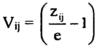

- die Vektoren (ci1(x,y), ci2(x,y))
mit 0 ≤ci1(x,y),ci2 (x,y) < 1 für den Körper fi jeweils die relative Position des Zentrums der Betrachtungselemente innerhalb der Zellen i des Motivbilds angeben, - die Vektoren (di1(x,y), di2(x,y))
mit 0 ≤ di1(x,y), di2(x,y) < 1 jeweils eine Verschiebung der Zellengrenzen im Motivbild darstellen, und - gij(x,y) Maskenfunktionen zur Einstellung der Sichtbarkeit des Körpers fi sind.
- a motif image, which is divided into a plurality of cells, in each of which imaged areas of the predetermined body are arranged,
- a viewing grid of a plurality of viewing elements for displaying the predetermined bodies when viewing the motif image using the viewing grid,
- wherein the motif image with its division into a plurality of cells has an image function m (x, y), which is given by
- where F (h 11, h 12,. .., h 1 n
1 , H 21, h 22. , , , h 2 n2 , . , , , h N 1 , h N 2 , ... h NnN ) is a master function indicating a concatenation of the descriptive functions h ij (x, y), and wherein - the unit cell of the viewing grid by grid cell vectors
- the magnification terms V ij are either scalars
- the vectors (c i1 (x, y), c i2 (x, y)) with 0 ≤c i1 (x, y), c i2 (x, y) <1 for the body f i, respectively, the relative position of the center indicate the viewing elements within the cells i of the motif image,
- the vectors (d i1 (x, y), d i2 (x, y)) with 0 ≦ d i1 (x, y), d i2 (x, y) <1 represent respectively a shift of the cell boundaries in the motif image, and
- g ij (x, y) are mask functions for adjusting the visibility of the body f i.
Alle bei den ersten drei Erfindungsaspekten für Einzel-Körper f gemachten Ausführungen gelten auch für die Mehrzahl an Körpern fi der allgemeineren Rasterbildanordnungen des vierten bis sechsten Erfindungsaspekts. Insbesondere kann zumindest eine (oder auch alle) der beschreibenden Funktionen des vierten, fünften oder sechsten Erfindungsaspektes wie oben für die Bildfunktion m(x,y) des ersten, zweiten oder dritten Erfindungsaspekts angegeben, gestaltet sein.All versions f made during the first three aspects of the invention for single body also apply to the plurality of bodies f i of the general raster image arrays of the fourth to sixth aspect of the invention. In particular, at least one (or even all) of the descriptive functions of the fourth, fifth or sixth aspect of the invention may be designed as indicated above for the image function m (x, y) of the first, second or third aspect of the invention.
Mit Vorteil stellt die Rasterbildanordnung ein Wechselbild, ein Bewegungsbild oder ein Morphbild dar. Die Maskenfunktionen gi bzw. gij können dabei insbesondere ein streifenartiges oder schachbrettartiges Wechseln der Sichtbarkeit der Körper fi festlegen. Eine Bilderfolge kann mit Vorteil beim Kippen entlang einer vorgegebenen Richtung ablaufen; in diesem Fall werden zweckmäßig streifenartige Maskenfunktionen gi bzw. gij verwendet, also Maskenfunktionen, die für jedes i nur in einem innerhalb der Einheitszelle wandernden Streifen ungleich Null sind. Im allgemeinen Fall können allerdings auch Maskenfunktionen gewählt werden, die eine Bilderfolge durch gekrümmte, mäanderförmige oder spiralförmige Kippbewegungen ablaufen lassen.Advantageously, the raster image arrangement represents a swap image, a motion image or a morph image. The mask functions g i or g ij can in particular define a strip-like or checkerboard-like change of the visibility of the body f i . An image sequence can advantageously take place when tilting along a predetermined direction; in this case expediently strip-like mask functions g i and g ij used, so the mask features that are, for each i, only in a traveling within the unit cell strips equal to zero. In the general case, however, it is also possible to select mask functions which allow a sequence of images to take place by means of curved, meandering or spiral tilting movements.
Während bei Wechselbildern (Kippbildern) oder anderen Bewegungsbildern idealerweise jeweils nur ein dreidimensionales Bild gleichzeitig sichtbar ist, enthält die Erfindung auch Gestaltungen, bei denen für den Betrachter gleichzeitig zwei oder mehr dreidimensionale Bilder (Körper) fi sichtbar sind. Dabei stellt die Masterfunktion F mit Vorteil die Summenfunktion, die Maximumsfunktion, eine ODER-Verknüpfung, eine XOR-Verknüpfung oder eine andere logische Verknüpfung dar.While in alternating images (tilt images) or other motion pictures ideally only one three-dimensional image is simultaneously visible, the invention also includes designs in which for the viewer two or more three-dimensional images (body) f i are simultaneously visible. The master function F advantageously represents the sum function, the maximum function, an OR operation, an XOR operation or another logical operation.
Das Motivbild liegt insbesondere in einer geprägten oder gedruckten Schicht vor. Nach einer vorteilhaften Weiterbildung der Erfindung weist das Sicherheitselement in allen Aspekten eine opake Abdeckschicht zur bereichsweisen Abdeckung der Rasterbildanordnung auf. Innerhalb des abgedeckten Bereichs tritt somit kein Modulo-Vergrößerungseffekt auf, so dass der optisch variable Effekt mit herkömmlichen Informationen oder mit anderen Effekten kombiniert werden kann. Diese Abdeckschicht liegt mit Vorteil in Form von Mustern, Zeichen oder Codierungen vor und/ oder weist Aussparungen in Form von Mustern, Zeichen oder Codierungen auf.The motif image is present in particular in an embossed or printed layer. According to an advantageous development of the invention, the security element has in all aspects an opaque cover layer for covering the raster image arrangement by area. Thus, no modulo magnification effect occurs within the covered area, so that the optically variable effect can be combined with conventional information or with other effects. This cover layer is advantageously in the form of patterns, characters or codes before and / or has recesses in the form of patterns, characters or codes.
Sind das Motivbild und das Betrachtungsraster an gegenüberliegenden Flächen einer optischen Abstandsschicht angeordnet, kann die Abstandsschicht beispielsweise eine Kunststofffolie und/oder eine Lackschicht umfassen.If the motif image and the viewing grid are arranged on opposite surfaces of an optical spacer layer, the spacer layer may comprise, for example, a plastic film and / or a lacquer layer.
Das permanente Sicherheitselement selbst stellt in allen Erfindungsaspekten bevorzugt einen Sicherheitsfaden, einen Aufreißfaden, ein Sicherheitsband, einen Sicherheitsstreifen, einen Patch oder ein Etikett zum Aufbringen auf ein Sicherheitspapier, Wertdokument oder dergleichen dar. In einer vorteilhaften Ausgestaltung kann das Sicherheitselement einen transparenten oder ausgesparten Bereich eines Datenträgers überspannen. Dabei können auf unterschiedlichen Seiten des Datenträgers unterschiedliche Erscheinungsbilder realisiert werden. Auch beidseitige Gestaltungen kommen infrage, bei denen beiderseits eines Motivbilds Betrachtungsraster angeordnet sind.The permanent security element itself in all aspects of the invention preferably represents a security thread, a tear-open thread, a security strip, a security strip, a patch or a label for application to a security paper, value document or the like. In an advantageous embodiment, the security element can form a transparent or recessed area Span the disk. Different appearances can be realized on different sides of the data carrier. Also two-sided designs come into question, in which both sides of a motif image viewing grid are arranged.
Die erfindungsgemäßen Rasterbildanordnungen können mit anderen Sicherheitsmerkmalen kombiniert werden, beispielsweise mit diffraktiven Strukturen, mit Hologrammstrukturen in allen Ausführungsvarianten, metallisiert oder nicht metallisiert, mit Subwellenlängenstrukturen, metallisiert oder nicht metallisiert, mit Subwellenlängengittern, mit Schichtsystemen, die beim Kippen einen Farbwechsel zeigen, semitransparent oder opak, mit diffraktiven optischen Elementen, mit refraktiven optischen Elementen, wie etwa Prismenstrahlformern, mit speziellen Lochformen, mit Sicherheitsmerkmalen mit gezielt eingestellter elektrischer Leitfähigkeit, mit eingearbeiteten Stoffen mit magnetischer Codierung, mit Stoffen mit phosphoreszierender, fluoreszierender oder lumineszierender Wirkung, mit Sicherheitsmerkmalen auf Grundlage von Flüssigkristallen, mit Mattstrukturen, mit Mikrospiegeln, mit Elementen mit Jalousie-Effekt oder mit Sägezahnstrukturen. Weitere Sicherheitsmerkmale, mit denen die erfindungsgemäßen Rasterbildanordnungen kombiniert werden können, sind in der Druckschrift
In allen Erfindungsaspekten können die Bildinhalte einzelner Zellen des Motivbilds nach der Bestimmung der Bildfunktion m(x,y) miteinander vertauscht sein.In all aspects of the invention, the image contents of individual cells of the motif image can be interchanged with one another after the determination of the image function m (x, y).
Die Erfindung enthält auch Verfahren zur Herstellung der Darstellungsanordnungen nach dem ersten bis sechsten Erfindungsaspekt, bei dem aus einem oder mehreren vorgegebenen dreidimensionalen Körpern ein Motivbild berechnet wird. Die Vorgehensweise und die benötigten rechnerischen Beziehungen für die allgemeine Perspektive, das Höhenprofil-Modell und das Schnittebene-Modell wurden bereits weiter oben angegeben und werden auch durch die nachfolgenden Ausführungsbeispiele näher erläutert.The invention also includes methods of making the display assemblies of the first to sixth aspects of the invention wherein a motif image is calculated from one or more predetermined three-dimensional bodies. The procedure and the required mathematical relationships for the general perspective, the height profile model and the sectional plane model have already been indicated above and are also explained in more detail by the following exemplary embodiments.
Die Größe der Motivbildelemente und der Betrachtungselemente liegt im Rahmen der Erfindung typischerweise bei etwa 5 bis 50 µm, so dass auch der Einfluss der Modulo-Vergrößerungsanordnung auf die Dicke der Sicherheitselemente gering gehalten werden kann. Die Herstellung derart kleiner Linsenarrays und derart kleiner Bilder ist beispielsweise in der Druckschrift
Eine typische Vorgehensweise ist dabei folgende: Zur Herstellung von Mikrostrukturen (Mikrolinsen, Mikrospiegel, Mikrobildelemente) können Techniken der Halbleiterstrukturierung verwendet werden, beispielsweise Photolithographie oder Elektronenstrahllithographie. Ein besonders geeignetes Verfahren besteht darin, die Strukturen mithilfe eines fokussierten Laserstrahls in Photolack zu belichten. Anschließend werden die Strukturen, die binäre oder komplexere dreidimensionale Querschnittsprofile aufweisen können, mit einem Entwickler freigelegt. Als alternatives Verfahren kann Laserablation eingesetzt werden.A typical procedure is the following: For the production of microstructures (microlenses, micromirrors, microimage elements), techniques of semiconductor structuring can be used, for example photolithography or electron beam lithography. A particularly suitable method is to expose the structures in photoresist by means of a focused laser beam. Subsequently, the structures, which may have binary or more complex three-dimensional cross-sectional profiles, are exposed with a developer. As an alternative method laser ablation can be used.
Das auf einem dieser Wege erhaltene Original kann zu einem Prägewerkzeug weiterverarbeitet werden, mit dessen Hilfe die Strukturen beispielsweise durch Prägen in UV-Lack, thermoplastisches Prägen oder durch die in der Druckschrift
Für das Endprodukt kommen eine Reihe verschiedener Ausführungsvarianten infrage: mit Metall bedampfte Prägestrukturen, Farbgebung durch metallische Nanostrukturen, Prägen in farbigen UV-Lack, Mikrotiefdruck nach der Druckschrift
Das Mikrolinsenarray kann ebenfalls mittels Laserablation oder Graustufen-Lithographie hergestellt werden. Alternativ kann eine Binärbelichtung erfolgen, wobei die Linsenform erst nachträglich durch Aufschmelzen von Photolack entsteht ("thermal reflow"). Aus dem Original kann - wie im Falle des Mikrostruktur-Arrays - ein Prägewerkzeug gefertigt werden, mit dessen Hilfe die Massenproduktion erfolgen kann, beispielsweise durch Prägen in UV-Lack oder thermoplastisches Prägen.The microlens array can also be fabricated by laser ablation or grayscale lithography. Alternatively, a binary exposure can take place, wherein the lens shape is formed only later by melting of photoresist ("thermal reflow"). From the original, as in the case of the microstructure array, an embossing tool can be produced with the aid of which mass production can take place, for example by embossing in UV lacquer or thermoplastic embossing.
Wird bei dekorativen Artikeln (z.B. Glückwunschkarten, Bilder als Wandschmuck, Vorhänge, Tischauflagen, Schlüsselanhänger, usw.) oder der Dekoration von Produkten das Modulo-Magnifierprinzip bzw. Modulo-Mappingprinzip angewandt, liegt die Größe der einzubringenden Bilder und Linsen bei etwa 50 bis 1000 µm. Hierbei können die einzubringenden Motivbilder mit konventionellen Druckverfahren, wie etwa Offsetdruck, Tiefdruck, Hochdruck, Siebdruck, oder digitalen Druckverfahren, wie etwa Tintenstrahldruck oder Laserdruck, farbig gedruckt werden.If the modulo-magnifier principle or modulo-mapping principle is used for decorative articles (eg greeting cards, pictures as wall decorations, curtains, table supports, key chains, etc.) or the decoration of products, the size of the images and lenses to be introduced is about 50 to 1000 microns. In this case, the motif images to be introduced can be printed in color using conventional printing methods, such as offset printing, gravure printing, letterpress printing, screen printing, or digital printing methods, such as inkjet printing or laser printing.
Das erfindungsgemäße Modulo-Magnifierprinzip bzw. Modulo-Mappingprinzip kann auch bei dreidimensional wirkenden Computer- und Fernseh-Bildern angewandt werden, die allgemein auf einer elektronischen Anzeigeeinrichtung gezeigt werden. Die Größe der einzubringenden Bilder und die Größe der Linsen in dem vor dem Bildschirm anzubringenden Linsenarray liegt in diesem Fall bei etwa 50 bis 500 µm. Die Bildschirmauflösung soll mindestens eine Größenordnung besser sein, so dass für diese Anwendung hochauflösende Bildschirme erforderlich sind.The modulo-magnifier principle or modulo-mapping principle according to the invention can also be used for three-dimensional computer and television images which are generally shown on an electronic display device. The size of the images to be introduced and the size of the lenses in the lens array to be mounted in front of the screen in this case is about 50 to 500 microns. The screen resolution should be at least an order of magnitude better, so that high-resolution screens are required for this application.
Schließlich enthält die Erfindung auch ein Sicherheitspapier für die Herstellung von Sicherheits- oder Wertdokumenten, wie Banknoten, Schecks, Ausweiskarten, Urkunden oder dergleichen, mit einer Darstellungsanordnung der oben beschriebenen Art. Die Erfindung enthält weiter einen Datenträger, insbesondere einen Markenartikel, ein Wertdokument, einen dekorativen Artikel, wie eine Verpackung, Postkarten oder dergleichen mit einer Darstellungsanordnung der oben beschriebenen Art. Das Betrachtungsraster und/oder das Motivbild der Darstellungsanordnung können dabei vollflächig, auf Teilflächen oder in einem Fensterbereich des Datenträgers angeordnet sein.Finally, the invention also includes a security paper for the production of security or value documents, such as banknotes, checks, identity cards, documents or the like, with a representation arrangement of the type described above. The invention further includes a data carrier, in particular a branded article, a value document, a decorative article, such as a package, postcards or the like with a representation arrangement of the type described above. The viewing grid and / or the motif image of the presentation arrangement can be arranged over the entire surface, on partial surfaces or in a window region of the data carrier.
Die Erfindung betrifft auch eine elektronische Anzeigeanordnung mit einer elektronischen Anzeigeeinrichtung, insbesondere einem Computer- oder Fernsehbildschirm, einer Steuereinrichtung und einer Darstellungsanordnung der oben beschriebenen Art. Die Steuereinrichtung ist dabei ausgelegt und eingerichtet, das Motivbild der Darstellungsanordnung auf der elektronischen Anzeigeeinrichtung anzuzeigen. Das Betrachtungsraster zur Betrachtung des angezeigten Motivbilds kann dabei mit der elektronischen Anzeigeeinrichtung verbunden sein oder kann ein separates Betrachtungsraster sein, das zur Betrachtung des angezeigten Motivbilds auf oder vor die elektronische Anzeigeeinrichtung bringbar ist.The invention also relates to an electronic display device having an electronic display device, in particular a computer or television screen, a control device and a display device of the type described above. The control device is designed and configured to display the motif image of the display device on the electronic display device. The viewing grid for viewing the displayed motif image can be connected to the electronic display device or can be a separate viewing grid, which can be brought onto or in front of the electronic display device for viewing the displayed motif image.
Alle beschriebenen Varianten können mit zweidimensionalen Linsenrastern in Gitteranordnungen beliebiger niederer oder höherer Symmetrie oder in Zylinderlinsen-Anordnungen ausgeführt werden. Alle Anordnungen können auch für gekrümmte Flächen berechnet werden, wie grundsätzlich in der Druckschrift
Weitere Ausführungsbeispiele sowie Vorteile der Erfindung werden nachfolgend anhand der Figuren erläutert. Zur besseren Anschaulichkeit wird in den Figuren auf eine maßstabs- und proportionsgetreue Darstellung verzichtet.Further embodiments and advantages of the invention are explained below with reference to the figures. For better clarity, a scale and proportioned representation is omitted in the figures.
Es zeigen:
- Fig.1
- eine schematische Darstellung einer Banknote mit einem eingebetteten Sicherheitsfaden und einem aufgeklebten Transferelement,
- Fig. 2
- schematisch den Schichtaufbau eines erfindungsgemäßen Sicherheitselements im Querschnitt,
- Fig. 3
- schematisch eine Seitenansicht eines darzustellenden Körpers im Raum, der perspektivisch in einer Motivbildebene dargestellt werden soll, und
- Fig. 4
- für das Höhenprofil-Modell in (a) eine zweidimensionale Darstellung f(x,y) eines darzustellenden Würfels in Zentralprojektion, in (b) die zugehörige Höhen/Tiefeninformation z(x,y) in Graucodierung und in (c) die mithilfe dieser Vorgaben berechnete Bildfunktion m(x,y).
- Fig.1
- a schematic representation of a banknote with an embedded security thread and a glued transfer element,
- Fig. 2
- schematically the layer structure of a security element according to the invention in cross-section,
- Fig. 3
- schematically a side view of a body to be displayed in space, which is to be shown in perspective in a scene image plane, and
- Fig. 4
- for the height profile model in (a) a two-dimensional representation f (x, y) of a cube to be displayed in central projection, in (b) the associated height / depth information z (x, y) in Gray coding and in (c) the image function m (x, y) calculated using these constraints.
Die Erfindung wird nun am Beispiel von Sicherheitselementen für Banknoten erläutert.
Sowohl der Sicherheitsfaden 12 als auch das Transferelement 16 können eine Modulo-Vergrößerungsanordnung nach einem Ausführungsbeispiel der Erfindung enthalten. Die Funktionsweise und das erfindungsgemäße Herstellungsverfahren für derartige Anordnungen werden im Folgenden anhand des Transferelements 16 näher beschrieben.Both the
Die Oberseite der Trägerfolie 20 ist mit einer rasterförmigen Anordnung von Mikrolinsen 22 versehen, die auf der Oberfläche der Trägerfolie ein zweidimensionales Bravais-Gitter mit einer vorgewählten Symmetrie bilden. Das Bravais-Gitter kann beispielsweise eine hexagonale Gittersymmetrie aufweisen. Möglich sind jedoch auch andere, insbesondere niedrigere Symmetrien und damit allgemeinere Formen, wie etwa die Symmetrie eines Parallelogramm-Gitters.The upper side of the carrier film 20 is provided with a grid-like arrangement of
Der Abstand benachbarter Mikrolinsen 22 ist vorzugsweise so gering wie möglich gewählt, um eine möglichst hohe Flächendeckung und damit eine kontrastreiche Darstellung zu gewährleisten. Die sphärisch oder asphärisch ausgestalteten Mikrolinsen 22 weisen vorzugsweise einen Durchmesser zwischen 5 µm und 50 µm und insbesondere einen Durchmesser zwischen lediglich 10 µm und 35 µm auf und sind daher mit bloßem Auge nicht zu erkennen. Es versteht sich, dass bei anderen Gestaltungen auch größere oder kleinere Abmessungen infrage kommen. Beispielsweise können die Mikrolinsen bei Modulo-Vergrößerungsanordnungen für Dekorationszwecke einen Durchmesser zwischen 50 µm und 5 mm aufweisen, während bei Modulo-Vergrößerungsanordnungen, die nur mit einer Lupe oder einem Mikroskop entschlüsselbar sein sollen, auch Abmessung unterhalb von 5 µm zum Einsatz kommen können.The spacing of
Auf der Unterseite der Trägerfolie 20 ist eine Motivschicht 26 angeordnet, die ein in eine Mehrzahl von Zellen 24 eingeteiltes Motivbild mit Motivbildelementen 28 enthält.On the underside of the carrier film 20, a
Die optische Dicke der Trägerfolie 20 und die Brennweite der Mikrolinsen 22 sind so aufeinander abgestimmt, dass sich die Motivschicht 26 etwa im Abstand der Linsenbrennweite befindet. Die Trägerfolie 20 bildet somit eine optische Abstandsschicht, die einen gewünschten, konstanten Abstand der Mikrolinsen 22 und der Motivschicht 26 mit dem Motivbild gewährleistet.The optical thickness of the carrier film 20 and the focal length of the
Zur Erläuterung der Funktionsweise der erfindungsgemäßen Modulo-Vergrößerungsanordnungen zeigt
Der Körper 30 wird ganz allgemein durch eine Körperfunktion f(x,y,z) und eine Transparenz-Stufenfunktion t(x,y,z) beschrieben, wobei die z-Achse senkrecht zu der durch die x- und y-Achse aufgespannten Zeichenebene 32 steht. Die Körperfunktion f(x,y,z) gibt eine charakteristische Eigenschaft des Körpers an der Stelle (x,y,z) an, beispielsweise eine Helligkeitsverteilung, eine Farbverteilung, eine Binärverteilung oder auch andere Körpereigenschaften, wie Transparenz, Reflektivität, Dichte oder dergleichen. Sie kann im Allgemeinen somit nicht nur eine skalare, sondern auch eine vektorwertige Funktion der Ortskoordinaten x, y und z darstellen. Die Transparenz-Stufenfunktion t(x,y,z) ist gleich 1, wenn der Körper an der Stelle (x,y,z) den Hintergrund verdeckt und ist ansonsten, also insbesondere, wenn der Körper an der Stelle (x,y,z) transparent oder nicht vorhanden ist, gleich 0.The
Es versteht sich, dass das darzustellende dreidimensionale Bild nicht nur ein einziges Objekt, sondern auch mehrere dreidimensionale Objekte umfassen kann, die nicht notwendigerweise zusammenhängen müssen. Die im Rahmen dieser Beschreibung verwendete Bezeichnung "Körper" wird im Sinne einer beliebigen dreidimensionalen Struktur gebraucht und schließt Strukturen mit einem oder mehreren getrennten dreidimensionalen Objekten ein.It is understood that the three-dimensional image to be displayed may comprise not only a single object but also a plurality of three-dimensional objects which need not necessarily be related. The term "body" used in this description is used in the sense of any three-dimensional structure and includes structures having one or more separate three-dimensional objects.
Die Anordnung der Mikrolinsen in der Linsenebene 34 wird durch ein zweidimensionales Bravais-Gitter beschrieben, dessen Einheitszelle durch Vektoren w1 und w2 (mit den Komponenten w11, w21, bzw. w12, w22) angegeben wird. In kompakter Schreibweise kann die Einheitszelle in Matrixform durch eine Linsenrastermatrix W angegeben werden: ![]()
![]()
Die Linsenrastermatrix W wird nachfolgend oft auch einfach Linsenmatrix oder Linsenraster genannt. Anstelle der Bezeichnung Linsenebene wird nachfolgend auch der Begriff Pupillenebene gebraucht. Die weiter unten als Pupillenpositionen bezeichneten Positionen xm, ym in der Pupillenebene stellen die Gitterpunkte des W-Gitters in der Linsenebene 34 dar.The lenticular matrix W is often referred to simply as a lens matrix or lenticular array hereinafter. Instead of the term lens plane, the term pupil plane is also used below. The positions x m , y m in the pupil plane designated below as pupil positions represent the grid points of the W grid in the
In der Linsenebene 34 können anstelle von Linsen 22 beispielsweise auch Lochblenden nach dem Prinzip der Lochkamera eingesetzt werden.In the
Auch alle anderen Arten von Linsen und abbildenden Systemen, wie asphärische Linsen, Zylinderlinsen, Schlitzblenden, mit Spiegeln versehene Loch- oder Schlitzblenden, Fresnellinsen, GRIN-Linsen (Gradient Refraction Index), Zonenplatten (Beugungslinsen), holographische Linsen, Hohlspiegel, Fresnelspiegel, Zonenspiegel und andere Elemente mit fokussierender oder auch ausblendender Wirkung, können als Betrachtungselemente im Betrachtungsraster eingesetzt werden.Also all other types of lenses and imaging systems, such as aspheric lenses, cylindrical lenses, slit diaphragms, apertured apertured or slit diaphragms, Fresnel lenses, GRIN (Gradient Refraction Index) lenses, zoned diffraction lenses, holographic lenses, concave mirrors, Fresnel mirrors, zone mirrors and other elements with focussing or also fading effect, can be used as viewing elements in the viewing grid.
Grundsätzlich können neben Elementen mit fokussierender Wirkung auch Elemente mit ausblendender Wirkung (Loch- oder Spaltblenden, auch Spiegelflächen hinter Loch- oder Spaltblenden) als Betrachtungselemente im Betrachtungsraster eingesetzt werden.Basically, in addition to elements with focussing effect elements with ausblendender effect (hole or slit, even mirror surfaces behind hole or slit) are used as viewing elements in the viewing grid.
Bei Anwendung eines Hohlspiegelarray und bei anderen erfindungsgemäß eingesetzten spiegelnden Betrachtungsrastern blickt der Betrachter durch das in diesem Fall teildurchlässige Motivbild auf das dahinterliegende Spiegelarray und sieht die einzelnen kleinen Spiegel als helle oder dunkle Punkte, aus denen sich das darzustellende Bild aufbaut. Das Motivbild ist dabei im Allgemeinen so fein strukturiert, dass es nur als Schleier zu sehen ist. Die beschriebenen Formeln für die Zusammenhänge zwischen dem darzustellenden Bild und dem Motivbild gelten, auch wenn dies im Einzelnen nicht erwähnt wird, nicht nur für Linsenraster, sondern auch für Spiegelraster. Es versteht sich dass bei erfindungsgemäßem Einsatz von Hohlspiegeln an die Stelle der Linsenbrennweite die Spiegelbrennweite tritt.When using a concave mirror array and in other inventively used specular viewing grids, the observer looks through the partially transparent in this case motif image on the underlying mirror array and sees the individual small mirror as light or dark points, from which builds the image to be displayed. The motif image is generally so finely structured that it can only be seen as a veil. The formulas described for the relationships between the image to be displayed and the motif image apply, even if this is not mentioned in detail, not only for lenticular, but also for mirror grid. It is understood that in the inventive use of concave mirrors in place of the lens focal length, the mirror focal length occurs.
Bei erfindungsgemäßer Anwendung eines Spiegelarray anstelle eines Linsenarray ist in
Mit Bezug wieder auf
An die Stelle (x,y,e) in der Zeichenebene 32 wird der im Körper zu entnehmende Wert f(xk,yk,zk(x,y,xm,ym)) eingetragen, wobei (xk,yk,zk(x,y,xm,ym)) der gemeinsame Punkt des Körpers 30 mit der charakteristischen Funktion t(x,y,z) und Sichtgerade [(xm, ym,0), (x, y, e)] mit dem kleinsten z-Wert ist.Of the body to be sampled value f (x k, y k, z k (x, y, x m, y m)) is applied to the location (x, y, e) in the
Dabei wird ein eventuelles Vorzeichen von z berücksichtigt, so dass nicht der Punkt mit dem betragsmäßig kleinsten z-Wert, sondern der Punkt mit dem negativsten z-Wert ausgewählt wird.In this case, a possible sign of z is taken into account, so that not the point with the smallest z-value, but the point with the most negative z-value is selected.
Betrachtet man zunächst nur einen im Raum stehenden Körper ohne Bewegungseffekte bei Kippen der Vergrößerungsanordnung, so ist das Motivbild in der Motivebene 32, das bei Betrachtung durch das in der Linsenebene 34 angeordnete Linsenraster W eine Darstellung des gewünschten Körpers erzeugt, durch eine Bildfunktion m(x,y) beschrieben, die erfindungsgemäß gegeben ist durch: 
Der Vektor (c1, c2), der im allgemeinen Fall ortsabhängig sein kann, also durch (c1(x,y),c2(x,y)) mit 0 ≤ c1(x,y), c2(x,y) < 1 gegeben sein kann, gibt dabei die relative Position des Zentrums der Betrachtungselemente innerhalb der Zellen des Motivbilds an.The vector (c 1 , c 2 ), which in the general case can be location-dependent, that is by (c 1 (x, y), c 2 (x, y)) with 0 ≤ c 1 (x, y), c 2 (x, y) <1, indicates the relative position of the center of the viewing elements within the cells of the motif image.
Die Berechnung von zk(x,y,xm,ym) ist im Allgemeinen sehr aufwendig, da im Linsenrasterbild 10 000 bis 1 000 000 und mehr Positionen (xm,ym) zu berücksichtigen sind. Weiter unter werden daher einige Verfahren aufgezeigt, bei denen zK unabhängig von (xm,ym) wird (Höhenprofil-Modell) bzw. sogar unabhängig von (x,y,xm,ym) wird (Schnittebenen-Modell).The computation of z k (x, y, x m , y m ) is generally very expensive, since in the
Zunächst wird jedoch noch eine Verallgemeinerung zu obiger Formel vorgestellt, bei der nicht nur im Raum stehende Körper dargestellt werden, sondern bei der sich der in der Linsenrastervorrichtung erscheinende Körper bei Änderung der Betrachtungsrichtung in der Tiefe verändert. Dazu wird anstelle der skalaren Vergrößerung v = z(x,y,xm,ym)/e eine Vergrößerungs- und Bewegungsmatrix A(x,y,xm,ym) verwendet, in der der Term v = z(x,y,xm,ym)/e enthalten ist.First, however, a generalization to the above formula is presented, in which not only standing in space body are shown, but in which the body appearing in the lenticular device changes in depth when changing the viewing direction. For this purpose, instead of the scalar magnification v = z (x, y, x m , y m ) / e, an enlargement and motion matrix A (x, y, x m , y m ) is used in which the term v = z (x , y, x m , y m ) / e is included.
Für die Bildfunktion m(x,y) ergibt sich dann 
Mit ![]()
![]()
![]()
![]()
Um die Berechnung des Motivbilds zu vereinfachen, geht man beim Höhenprofil von einer zweidimensionalen Zeichnung f(x,y) eines Körpers aus, wobei zu jedem Punkt x,y des zweidimensionalen Bildes des Körpers eine zusätzliche z-Koordinate z(x,y) angibt, wieweit sich dieser Punkt im wirklichen Körper von der Zeichenebene 32 entfernt befindet. z(x,y) kann dabei sowohl positive als auch negative Werte annehmen.In order to simplify the calculation of the motif image, the height profile is based on a two-dimensional drawing f (x, y) of a body, with an additional z-coordinate z (x, y) given for each point x, y of the two-dimensional image of the body How far is this point in the real body away from the drawing
Zur Illustration zeigt
Im Fall einer reinen Vergrößerung ergibt sich aus den Angaben von f(x,y) und z(x,y) für die Bildfunktion 

Sollen nicht nur im Raum stehende Körper dargestellt werden, sondern sollen sich die in der Linsenrastervorrichtung erscheinenden Körper bei Änderung der Betrachtungsrichtung in der Tiefe verändern, so tritt anstelle der Vergrößerung v = z(x,y)/e eine Vergrößerungs- und Bewegungsmatrix A(x,y): 

Es werden zwei Höhenfunktionen z1(x,y) und z2(x,y) vorgegeben, so dass die Vergrößerungs- und Bewegungsmatrix A(x,y) die Gestalt 
Es werden zwei Höhenfunktionen z1(x,y) und z2(x,y) und zwei Winkel φ1 und φ2 vorgegeben, so dass die Vergrößerungs- und Bewegungsmatrix A(x,y) die Gestalt 
Bei normaler Betrachtung (Augenabstandsrichtung in x-Richtung) sieht man den Körper im Höhenrelief z1(x,y) und beim Kippen der Anordnung in x-Richtung bewegt sich der Körper in Richtung φ1 zur x-Achse.In normal viewing (eye distance direction in x-direction) one sees the body in the height relief z 1 (x, y) and when tilting the arrangement in the x-direction the body moves in the direction φ 1 to the x-axis.
Bei um 90° gedrehter Betrachtung (Augenabstandsrichtung in y-Richtung) sieht man den Körper im Höhenrelief z2(x,y) und beim Kippen der Anordnung in y-Richtung bewegt sich der Körper in Richtung φ2 zur x-Achse.When rotated by 90 ° viewing (eye distance direction in y-direction) you can see the body in height relief z 2 (x, y) and when tilting the arrangement in the y-direction, the body moves in the direction of φ 2 to the x-axis.
Es werden eine Höhenfunktion z(x,y) und ein Winkel φ1 vorgegeben, so dass die Vergrößerungs- und Bewegungsmatrix A(x,y) die Gestalt 
In diesem Ausführungsbeispiel ist die Betrachtung auch mit einem passenden Zylinderlinsenraster möglich, beispielsweise mit einem Spaltraster oder Zylinderlinsenraster, dessen Einheitszelle durch 

Bei einer Zylinderlinsen-Achse in beliebiger Richtung γ und mit Achsenabstand d, also einem Linsenraster 

Das hiermit für das hinter einem Linsenraster W anzulegende Druck- oder Prägebild erzeugte Muster lässt sich nicht nur mit dem Spaltblenden- bzw. Zylinderlinsen-Array mit Achse in Richtung γ betrachten, sondern auch mit einem Lochblenden- bzw. Linsenarray mit 
Es werden zwei Höhenfunktionen z1(x,y) und z2(x,y) und ein Winkel φ2 vorgegeben, so dass die Vergrößerungs- und Bewegungsmatrix A(x,y) die Gestalt 
Weiter weist die Anordnung einen orthoparallaktischen 3D-Effekt auf, wobei sich der Körper bei üblicher Betrachtung (Augenabstandsrichtung in x-Richtung) und beim Kippen der Anordnung in x-Richtung senkrecht zur x-Achse bewegt.Furthermore, the arrangement has an orthoparallactic 3D effect, wherein the body is in normal viewing (eye distance direction in the x direction) and moved when tilting the arrangement in the x-direction perpendicular to the x-axis.
Bei um 90° gedrehter Betrachtung (Augenabstandsrichtung in y-Richtung) und beim Kippen der Anordnung in y-Richtung bewegt sich der Körper in Richtung φ2 zur x-Achse.When rotated by 90 ° viewing (eye distance direction in the y direction) and tilting the arrangement in the y direction, the body moves in the direction of φ 2 to the x-axis.
Eine dreidimensionale Wirkung kommt hier bei üblicher Betrachtung (Augenabstandsrichtung in x-Richtung) allein durch Bewegung zustande.A three-dimensional effect comes about here in normal observation (eye distance direction in x-direction) only by movement.
Beim Schnittebenen-Modell wird der dreidimensionale Körper zur Vereinfachung der Berechnung des Motivbilds durch n Schnitte fj (x,y) und n Transparenz-Stufenfunktionen tj(x,y) mit j = 1,...n, vorgegeben, die zum Beispiel bei Betrachtung mit Augenabstand in x-Richtung jeweils in einer Tiefe zj, zj > zj-1 liegen. Die Aj-Matrix muss dann so gewählt werden, dass der linke obere Koeffizient gleich zj /e ist.In the cut-plane model, the three-dimensional body is given by n cuts fj (x, y) and n transparency step functions tj (x, y) with j = 1, ... n, for example, to simplify the calculation of the motif image when viewed with eye relief in the x-direction each lie at a depth z j , z j > z j-1 . The A j matrix must then be chosen such that the upper left coefficient is equal to z j / e.
Dabei ist fj(x,y) die Bildfunktion des j-ten Schnitts, die eine Helligkeitsverteilung (Graustufenbild), eine Farbverteilung (Farbbild), eine Binärverteilung (Strichzeichnung) oder auch andere Bildeigenschaften, wie Transparenz, Reflektivität, Dichte oder dergleichen, angeben kann. Die Transparenz-Stufenfunktion tj(x,y) ist gleich 1, wenn der Schnitt j an der Stelle (x,y) dahinterliegende Objekte verdeckt und ist ansonsten gleich 0.In this case, f j (x, y) is the image function of the jth section indicating a brightness distribution (grayscale image), a color distribution (color image), a binary distribution (line drawing) or other image properties such as transparency, reflectivity, density or the like can. The transparency step function t j (x, y) is equal to 1 if the intersection j conceals objects behind it at the position (x, y) and is otherwise equal to 0.
Für die Bildfunktion m(x,y) ergibt sich dann 

Ein holzschnittartiges oder kupferstichartiges 3D-Bild erhält man beispielsweise, wenn die Schnitte fj, tj in folgender Weise durch mehrere Funktionswerte beschrieben werden:A woodcut or copper engraving 3D image is obtained, for example, if the sections f j , t j are described by several function values in the following way:
fj = Schwarz-Weiß-Wert (bzw. Graustufenwert) auf der Konturlinie oder Schwarz-Weiß-Werte (bzw. Graustufenwerte) in unterschiedlich ausgedehnten, an den Rand anschließenden Bereichen der Schnittfigur, und 
Zur Illustration des Schnittebenen-Modells seien auch hier einige Spezialfälle behandelt:To illustrate the cutting plane model, here are some special cases:
Im einfachsten Fall ist die Vergrößerungs- und Bewegungsmatrix gegeben durch 
Bei allen Betrachtungsrichtungen, allen Augenabstandsrichtungen und beim Drehen der Anordnung bleibt die Tiefe unverändert.In all viewing directions, all eye distance directions, and when rotating the assembly, the depth remains unchanged.
Es wird ein Änderungsfaktor k ungleich 0 vorgegeben, so dass die Vergrößerungs- und Bewegungsmatrix Aj die Gestalt 
Es wird ein Änderungsfaktor k ungleich 0 und zwei Winkel φ1 und φ2 vorgegeben, so dass die Vergrößerungs- und Bewegungsmatrix Aj die Gestalt 
Es wird ein Winkel φ1 vorgegeben, so dass die Vergrößerungs- und Bewegungsmatrix Aj die Gestalt 
In diesem Ausführungsbeispiel ist die Betrachtung auch mit einem passenden Zylinderlinsenraster möglich, beispielsweise mit einem Spaltraster oder Zylinderlinsenraster, dessen Einheitszelle durch ![]()
![]()
Er werden ein Änderungsfaktor k ungleich 0 und ein Winkel φ vorgegeben, so dass die Vergrößerungs- und Bewegungsmatrix Aj die Gestalt 
Er werden ein Änderungsfaktor k ungleich 0 und ein Winkel φ1 vorgegeben, so dass die Vergrößerungs- und Bewegungsmatrix Aj die Gestalt 
Nachfolgend werden weitere Ausgestaltungen der Erfindung dargestellt, die jeweils am Beispiel des Höhenprofil-Modells erläutert werden, bei dem der darzustellende Körper entsprechend der obigen Erläuterung durch eine zweidimensionale Zeichnung f(x,y) und eine Höhenangabe z(x,y) dargestellt ist. Es versteht sich, dass die nachfolgend beschriebenen Ausführungsformen jedoch auch im Rahmen der allgemeinen Perspektive und des Schnittebenen-Modells eingesetzt werden können, wobei die zweidimensionale Funktion f(x,y) dann entsprechend durch die dreidimensionalen Funktionen f(x,y,z) und t(x,y,z) bzw. die Schnittbilder fj(x,y) und tj(x,y) ersetzt werden.Hereinafter, further embodiments of the invention are shown, which are each explained using the example of the height profile model, in which the body to be displayed according to the above explanation by a two-dimensional drawing f (x, y) and a height indication z (x, y) is shown. However, it is understood that the embodiments described below also in the context of the general perspective and the sectional plane model The two-dimensional function f (x, y) can then be used correspondingly by the three-dimensional functions f (x, y, z) and t (x, y, z) or the sectional images f j (x, y) and t j (x, y) are replaced.
Für das Höhenprofil-Modell ist die Bildfunktion m(x,y) allgemein gegeben durch 


Der Vergrößerungsterm V(x,y) ist im Allgemeinen eine Matrix V(x,y) =(A(x,y) - I), wobei die Matrix 
![]()
![]()
Der Vektor (c1(x,y), c2(x,y)) mit 0 ≤ c1(x,y),c2 (x,y) < 1 gibt die relative Position des Zentrums der Betrachtungselemente innerhalb der Zellen des Motivbilds an. Der Vektor (d1(x,y), d2(x,y)) mit 0 ≤ d1 (x, y), d2 (x, y) < 1 stellt eine Verschiebung der Zellengrenzen im Motivbild dar, und g(x,y) ist eine Maskenfunktion zur Einstellung der Sichtbarkeit des Körpers.The vector (c 1 (x, y), c 2 (x, y)) with 0≤c 1 (x, y), c 2 (x, y) <1 gives the relative position of the center of the viewing elements within the cells of the motif image. The vector (d 1 (x, y), d 2 (x, y)) with 0≤d 1 (x, y), d 2 (x, y) <1 represents a shift of the cell boundaries in the motif image, and g (x, y) is a mask function for adjusting the visibility of the body.
Für manche Anwendungen kann eine Winkelbeschränkung bei der Betrachtung der Motivbilder erwünscht sein, d.h. das dargestellte dreidimensionale Bild soll nicht aus allen Richtungen sichtbar oder sogar nur in einem kleinen Raumwinkelbereich zu erkennen sein.For some applications, an angle constraint may be desirable when viewing the motif images, i. The illustrated three-dimensional image should not be visible from all directions or even be recognized only in a small solid angle range.
Eine solche Winkelbeschränkung kann insbesondere in Kombination mit den weiter unten beschriebenen Wechselbildern von Vorteil sein, da das Umschalten von einem Motiv zum anderen im Allgemeinen nicht von beiden Augen gleichzeitig wahrgenommen wird. Dies kann dazu führen, dass während des Umschaltens ein unerwünschtes Doppelbild als Überlagerung benachbarter Bildmotive zu sehen ist. Werden die Einzelbilder jedoch durch einen Rand geeigneter Breite gesäumt, kann eine solche visuell unerwünschte Überlagerung unterdrückt werden.Such an angle restriction may be particularly advantageous in combination with the alternate frames described below since switching from one subject to another is generally not perceived by both eyes simultaneously. This can lead to an unwanted double image being seen as a superimposition of adjacent image motifs during the switchover. However, if the frames are bordered by an edge of appropriate width, such visually undesirable overlay can be suppressed.
Weiter hat sich gezeigt, dass die Abbildungsqualität bei schräger Aufsicht auf das Linsenarray unter Umständen deutlich nachlassen kann: Während bei senkrechter Betrachtung der Anordnung ein scharfes Bild zu erkennen ist, wird das Bild in diesem Fall bei zunehmendem Kippwinkel unschärfer und wirkt verschwommen. Aus diesem Grund kann eine Winkelbeschränkung auch bei der Darstellung einzelner Bilder vorteilhaft sein, wenn sie insbesondere die Flächenbereiche zwischen den Linsen, die erst bei relativ hohen Kippwinkeln durch die Linsen sondiert werden, ausblendet. Dadurch verschwindet das dreidimensionale Bild für den Betrachter beim Kippen, ehe es verschwommen wahrgenommen werden kann.Furthermore, it has been shown that the image quality can slacken significantly under oblique view of the lens array under certain circumstances: While a sharp image can be seen when viewed vertically from the arrangement, the image is blurred in this case with increasing tilt angle and blurred. For this reason, an angle restriction may also be advantageous in the representation of individual images if, in particular, it fades out the surface areas between the lenses, which are only probed through the lenses at relatively high tilt angles. As a result, the three-dimensional image for the viewer disappears when tilted, before it can be perceived blurry.
Eine solche Winkelbeschränkung kann durch eine Maskenfunktion g ≠ 1 in der allgemeinen Formel für das Motivbild m(x,y) erreicht werden. Ein einfaches Beispiel für eine solche Maskenfunktion ist 
Es versteht sich, dass die Funktion g(x,y) im Allgemeinen die Verteilung belegter und freier Flächen innerhalb einer Zelle beliebig vorgeben kann.It is understood that the function g (x, y) can generally arbitrarily specify the distribution of occupied and free areas within a cell.
Neben einer Winkelbeschränkung können Maskenfunktionen als Bildfeldbeschränkung auch Bereiche definieren, in denen das dreidimensionale Bild nicht sichtbar wird. Die Bereiche in denen g=0 ist, können sich in diesem Fall über eine Vielzahl von Zellen erstrecken. Beispielsweise können die weiter unten genannten Ausgestaltungen mit nebeneinanderliegenden Bildern durch solche makroskopische Maskenfunktionen beschrieben werden. Allgemein ist eine Maskenfunktion zur Bildfeldbeschränkung gegeben durch 
Bei der Verwendung einer Maskenfunktion g ≠ 1 erhält man für den Fall von ortsunabhängigen Zellengrenzen im Motivbild aus der Formel für die Bildfunktion m(x,y): 
Bei den bisher beschriebenen Beispielen war der Vektor (d1(x,y), d2(x,y)) identisch Null, die Zellengrenzen waren über die ganze Fläche gleichförmig verteilt. In manchen Ausgestaltungen kann es jedoch auch von Vorteil sein, das Raster der Zellen in der Motivebene ortsabhängig zu verschieben, um beim Ändern der Betrachtungsrichtung spezielle optische Effekte zu erzielen. Mit g≡1 stellt sich die Bildfunktion m(x,y) dann in der Form 
Auch der Vektor (c1(x,y), c2(x,y)) kann eine Funktion des Ortes sein. Mit g ≡ 1 stellt sich die Bildfunktion m(x,y) dann in der Form 

Wie weiter oben erläutert, beschreibt der Vektor (c1(x,y),c2(x,y)) die Position der Zellen in der Motivbildebene relativ zum Linsenarray W, wobei als Bezugspunktemenge das Raster der Linsenzentren betrachtet werden kann. Ist der Vektor (c1(x,y), c2(x,y)) eine Funktion des Ortes, so bedeutet dies, dass Änderungen von (c1(x,y), c2(x,y)) sich in einer Änderung der relativen Positionierung zwischen den Zellen in der Motivbildebene und den Linsen manifestieren, was zu Schwankungen in der Periodizität der Motivbildelemente führt.As explained above, the vector (c 1 (x, y), c 2 (x, y)) describes the position of the cells in the scene image plane relative to the lens array W, whereby the raster of the lens centers can be considered as the reference point set. If the vector (c 1 (x, y), c 2 (x, y)) is a function of the location, this means that changes in (c 1 (x, y), c 2 (x, y)) occur in a change in relative positioning between the cells in the scene image plane and the lenses, resulting in variations in the periodicity of the motif picture elements.
Beispielsweise kann eine Ortsabhängigkeit des Vektors (c1(x,y),c2(x,y)) vorteilhaft eingesetzt werden, wenn eine Folienbahn verwendet wird, die auf der Vorderseite eine Linsenprägung mit vollflächig homogenem Raster W trägt. Prägt man auf der Rückseite eine Modulo-Vergrößerungsanordnung mit ortsunabhängigem (c1(x,y), c2(x,y)) ein, so bleibt es dem Zufall überlassen, unter welchen Betrachtungswinkeln man welche Features erkennt, wenn keine exakte Registrierung zwischen Vorder- und Rückseitenprägung möglich ist. Variiert man hingegen (c1(x,y), c2(x,y)) quer zur Folienlaufrichtung, so findet sich ein streifenförmiger Bereich in Laufrichtung der Folie, der die geforderte Positionierung zwischen Vorder- und Rückseitenprägung erfüllt.For example, a location dependence of the vector (c 1 (x, y), c 2 (x, y)) can advantageously be used if a film web is used which carries a lens embossing on the front side with a homogeneous homogeneous pattern W. If a modulo magnification arrangement with location-independent (c 1 (x, y), c 2 (x, y)) is impressed on the rear side, it is left to chance, under which viewing angles one recognizes which features, if there is no exact registration between Front and back side embossing is possible. If, however, one varies (c 1 (x, y), c 2 (x, y)) transversely to the direction of film travel, then a strip-shaped region is found in the direction of travel of the film, which fulfills the required positioning between front and back side embossing.
Darüber hinaus kann man (c1(x,y), c2(x,y)) beispielsweise auch in Laufrichtung der Folie variieren, um in jedem Streifen in Längsrichtung der Folie Abschnitte vorzufinden, welche die richtige Registrierung aufweisen. Dadurch lässt sich verhindern, dass metallisierte Hologrammstreifen oder Sicherheitsfäden von Banknote zu Banknote unterschiedlich aussehen.In addition, (c 1 (x, y), c 2 (x, y)) can also be varied, for example, in the running direction of the film in order to find sections in each strip in the longitudinal direction of the film which have the correct registration. This makes it possible to prevent the appearance of metallized hologram strips or security threads from banknote to banknote.
In einem weiteren Ausführungsbeispiel soll das dreidimensionale Bild nicht nur bei Betrachtung durch ein normales Loch/Linsenraster, sondern auch bei Betrachtung durch ein Spaltraster oder Zylinderlinsenraster sichtbar sein, wobei als dreidimensionales Bild insbesondere ein sich nicht periodisch wiederholendes Einzelbild vorgegeben sein kann.In a further exemplary embodiment, the three-dimensional image should not only be visible when viewed through a normal hole / lenticular grid, but also when viewed through a slit grid or cylindrical lens grid, wherein a three-dimensional image can be given in particular a non-periodically repeating individual image.
Auch dieser Fall kann durch die allgemeine Formel für m(x,y) beschrieben werden, wobei man, wenn das anzulegende Motivbild in Spalt/Zylinderrichtung nicht gegenüber dem darzustellenden Bild transformiert ist, eine spezielle Matrix A benötigt, die folgendermaßen ermittelt werden kann:This case can also be described by the general formula for m (x, y), wherein, if the motif image to be applied is not transformed in the gap / cylinder direction with respect to the image to be displayed, a special matrix A is needed, which can be determined as follows:
Liegt die Zylinderachsenrichtung in y-Richtung und ist der Zylinderachsenabstand d, so wird das Spalt- oder Zylinderlinsenraster beschrieben durch: ![]()
![]()
Die passende Matrix A, bei der in y-Richtung keine Vergrößerung oder Verzerrung vorliegt, ist dann: 
Dabei wirkt die Matrix (A-I) in der Beziehung (A-I)W nur auf die erste Zeile von W, so dass W einen unendlich langen Zylinder darstellen kann.In this case, the matrix (A-1) in the relationship (A-1) W acts only on the first row of W, so that W can represent an infinitely long cylinder.
Das anzulegende Motivbild mit der Zylinderachse in y-Richtung ergibt sich dann zu: 


Linsenarray mit 
Bei den bisherigen Ausführungen stellt die Modulo-Vergrößerungsanordnung bei der Betrachtung meist ein einzelnes dreidimensionales Bild (Körper) dar. Die Erfindung umfasst jedoch auch Gestaltungen, bei denen mehrere dreidimensionale Bilder gleichzeitig oder im Wechsel dargestellt werden.In the previous embodiments, the modulo magnification arrangement usually represents a single three-dimensional image (body) when viewed. However, the invention also encompasses configurations in which several three-dimensional images are displayed simultaneously or alternately.
Bei der gleichzeitigen Darstellung können die dreidimensionalen Bilder insbesondere verschiedenes Bewegungsverhalten beim Kippen der Anordnung aufweisen. Bei im Wechsel dargestellten dreidimensionalen Bildern können diese insbesondere beim Kippen der Anordnung ineinander übergehen. Die verschiedenen Bilder können voneinander unabhängig sein oder inhaltlich aufeinander bezogen sein und beispielsweise einen Bewegungsablauf darstellen.In the simultaneous representation, the three-dimensional images can in particular have different movement behavior when tilting the arrangement. In three-dimensional images shown in alternation these can merge into one another in particular when tilting the arrangement. The different images can be independent of each other or content related to each other and represent, for example, a movement.
Auch hier wird das Prinzip am Beispiel des Höhenprofil-Modells erläutert, wobei sich wieder versteht, dass die beschriebenen Ausführungsformen bei entsprechender Anpassung bzw. Ersetzung der Funktionen fi(x,y) auch im Rahmen der allgemeinen Perspektive mit Körperfunktionen fi(x,y,z) und Transparenz-Stufenfunktionen ti(x,y,z) bzw. im Rahmen des Schnittebenen-Modells mit Schnittbildern fij(x,y) und Transparenz-Stufenfunktionen tij(x,y) eingesetzt werden können.Here, too, the principle is explained using the example of the height profile model, it being understood again that the embodiments described with appropriate adaptation or replacement of the functions f i (x, y) also in the context of the general perspective with body functions f i (x, y, z) and transparency step functions t i (x, y, z) or in the context of the sectional plane model with sectional images f ij (x, y) and transparency step functions t ij (x, y) can be used.
Es soll eine Mehrzahl N≥1 vorgegebener dreidimensionaler Körper dargestellt werden, die durch Höhenprofile mit zweidimensionalen Darstellungen der Körper fi(x,y), i=1,2,...N und durch Höhenfunktionen zi(x,y) gegeben sind, die jeweils für jeden Punkt (x,y) des vorgegebenen Körpers fi eine Höhen-/Tiefeninformation enthalten. Für das Höhenprofil-Modell ist die Bildfunktion m(x,y) dann allgemein gegeben durch ![]()


![]()
Dabei ist F(h 1,h 2,...hN ) eine Masterfunktion, die eine Verknüpfung der N beschreibenden Funktionen hi(x,y) angibt. Die Vergrößerungsterme Vi(x,y) sind entweder Skalare ![]()
![]()

![]()
![]()
Ein einfaches Beispiel für Gestaltungen mit mehreren dreidimensionalen Bildern (Körpern) ist ein einfaches Kippbild, bei dem sich zwei dreidimensionale Körper f1(x,y) und f2(x,y) abwechseln, sobald das Sicherheitselement in entsprechender Weise gekippt wird. Unter welchen Betrachtungswinkeln der Wechsel zwischen den beiden Körpern stattfindet, wird durch die Maskenfunktionen g1 und g2 festgelegt. Um zu verhindern, dass - selbst bei Betrachtung mit nur einem Auge - beide Bilder gleichzeitig zu sehen sind, werden die Träger der Funktionen g1 und g2 disjunkt gewählt.A simple example of multi-dimensional image (body) designs is a simple tilt image in which two three-dimensional bodies f 1 (x, y) and f 2 (x, y) alternate as the security element is tilted in a similar manner. Under what angles the change between the two bodies takes place is determined by the mask functions g 1 and g. 2 To prevent - even when viewing with only one eye - both images can be seen simultaneously, the carriers of the functions g 1 and g 2 are chosen disjointly.
Als Masterfunktion F wird die Summenfunktion gewählt. Damit ergibt sich für die Bildfunktion des Motivbilds m(x,y): 


![]()
![]()
Statt schachbrettartig können sich die dargestellten Bilder auch streifenweise abwechseln, beispielsweise durch Verwendung der folgenden Maskenfunktionen: 

In diesem Fall tritt ein Wechsel der Bildinformation auf, wenn das Sicherheitselement entlang der durch den Vektor (w11, w21) angegebenen Richtung gekippt wird, wohingegen Kippen entlang des zweiten Vektors (w12,w22) zu keinem Bildwechsel führt. Auch hier wurde die Grenze bei 0,5 gewählt, d.h. die Fläche des Motivbilds wurde in Streifen gleicher Breite aufgeteilt, die abwechselnd die Informationen der beiden dreidimensionalen Bilder enthalten.In this case, a change of image information occurs when the security element is tilted along the direction indicated by the vector (w 11 , w 21 ), whereas tilting along the second vector (w 12 , w 22 ) results in no image change. Again, the border was chosen at 0.5, ie the area of the motif image was divided into strips of equal width, which alternately contain the information of the two three-dimensional images.
Liegen die Streifengrenzen exakt unter den Linsenmittelpunkten bzw. den Linsengrenzen, so sind die Raumwinkelbereiche, unter denen die beiden Bilder zu sehen sind, gleich verteilt: beginnend bei senkrechtem Aufblick sieht man von der rechten Hälfte der Hemisphäre aus betrachtet zunächst das eine der beiden dreidimensionalen Bilder, von der linken Hälfte der Hemisphäre zunächst das andere dreidimensionale Bild. Im Allgemeinen kann die Grenze zwischen den Streifen natürlich beliebig gelegt werden.If the borders of the stripes lie exactly under the lens centers or the lens boundaries, then the solid angle ranges under which the two images can be seen are distributed equally: starting with a vertical view, one of the two three-dimensional images is first seen from the right half of the hemisphere , from the left half of the Hemisphere first, the other three-dimensional image. In general, the boundary between the stripes can of course be arbitrarily set.
Bei dem nunmehr beschriebenen Modulo-Morphing oder Modulo-Cinema stehen die verschiedenen dreidimensionalen Bilder in direktem Sinnzusammenhang, wobei sich im Fall des Modulo-Morphing ein Startbild über eine definierte Anzahl von Zwischenstadien in ein Endbild verwandelt, und beim Modulo-Cinema vorzugsweise einfache Bewegungsabläufe gezeigt werden.In the case of modulo-morphing or modulo-cinema, the various three-dimensional images are directly related, wherein in the case of modulo morphing, a starting image is transformed into a final image over a defined number of intermediate stages, and preferably simple sequences of motion are displayed in the modulo-cinema become.
Die dreidimensionalen Bilder seien im Höhenprofil-Modell durch Bilder 


Verallgemeinernd kann auch hier anstelle der in der Formel ausgedrückten regelmäßigen Aufteilung die Streifenbreite unregelmäßig gewählt werden.In general, here too, instead of the regular distribution expressed in the formula, the stripe width can be selected irregularly.
Es ist zwar zweckmäßig, die Bilderfolge durch Kippen entlang einer Richtung (lineare Kippbewegung) abzurufen, zwingend erforderlich ist dies allerdings nicht. Stattdessen können die Morph- bzw. Bewegungseffekte beispielsweise auch durch mäanderförmige oder spiralenförmige Kippbewegungen abgespielt werden.Although it is expedient to retrieve the image sequence by tilting along one direction (linear tilting movement), this is not absolutely necessary. Instead, the morphing or movement effects can also be played, for example, by meander-shaped or spiral-shaped tilting movements.
Bei den Beispielen 14 und 15 war grundsätzlich das Ziel, aus einer bestimmten Betrachtungsrichtung immer nur ein einziges dreidimensionales Bild erkennen zu lassen, nicht jedoch zwei oder mehrere gleichzeitig. Die gleichzeitige Sichtbarkeit mehrerer Bilder ist im Rahmen der Erfindung jedoch ebenfalls möglich und kann zu attraktiven optischen Effekten führen. Die verschiedenen dreidimensionalen Bilder fi können dabei völlig unabhängig voneinander behandelt werden. Dies gilt sowohl für die jeweiligen Bildinhalte, als auch für die scheinbare Lage der dargestellten Objekte und deren Bewegung im Raum.In the examples 14 and 15 was basically the goal, from a certain viewing direction only ever recognize a single three-dimensional image, but not two or more simultaneously. However, the simultaneous visibility of multiple images within the scope of the invention is also possible and can lead to attractive visual effects. The different three-dimensional images f i can be treated completely independently of each other. This applies both to the respective image contents, as well as to the apparent position of the depicted objects and their movement in space.
Während die Bildinhalte mithilfe von Zeichnungen wiedergegeben werden können, werden Lage und Bewegung der dargestellten Objekte in den Dimensionen des Raums mithilfe der Bewegungsmatrizen Ai beschrieben. Auch die relative Phase der einzelnen dargestellten Bilder kann individuell eingestellt werden, wie durch die Koeffizienten cij in der allgemeinen Formel für m(x,y) ausgedrückt. Die relative Phase steuert, bei welchen Betrachtungsrichtungen die Motive zu erkennen sind. Wird der Einfachheit halber für die Maskenfunktionen gi jeweils die Einheitsfunktion gewählt, sind die Zellengrenzen im Motivbild nicht ortsabhängig verschoben, und wird als Masterfunktion F die Summenfunktion gewählt, so ergibt sich für eine Reihe übereinandergelegter dreidimensionaler Bilder fi: 
Bei der Überlagerung mehrerer Bilder entspricht die Verwendung der Summenfunktion als Masterfunktion je nach Charakter der Bildfunktion f einer Addition der Grau-, Farb-, Transparenz- oder Dichte-Werte, wobei die resultierenden Bildwerte bei Überschreiten des maximalen Wertebereichs typischerweise auf den Maximalwert gesetzt werden.When superimposing several images, the use of the sum function as a master function corresponds to an addition of the gray, color, transparency or density values depending on the character of the image function f, the resulting image values typically being set to the maximum value when the maximum value range is exceeded.
Es kann jedoch auch günstiger sein, andere Funktionen als die Summenfunktion für die Masterfunktion F zu wählen, beispielsweise eine ODER-Verknüpfung, eine Exklusiv-Oder- (XOR)-Verknüpfung oder die Maximumsfunktion. Weitere Möglichkeiten bestehen darin, das Signal mit dem geringsten Funktionswert zu wählen, oder wie oben die Summe aller an einem bestimmten Punkt zusammentreffender Funktionswerte zu bilden. Gibt es eine maximale Obergrenze, beispielsweise die maximale Belichtungsintensität eines Laserbelichters, so kann man die Summe bei diesem Maximalwert abschneiden.However, it may also be more convenient to choose functions other than the sum function for the master function F, such as an OR, an exclusive-OR (XOR), or the maximum function. Other possibilities are to select the signal with the lowest value of function or, as above, to form the sum of all function values meeting at a certain point. If there is a maximum upper limit, for example the maximum exposure intensity of a laser exposure, then one can cut off the sum at this maximum value.
Durch passende Sichtbarkeitsverknüpfungen, Mischung und Überlagerung mehrerer Bilder können z.B. auch "3D-Röntgenbilder" dargestellt werden, wobei eine "Außenhaut" und ein "Innenskelett" gemischt und überlagert werdenBy appropriate visibility links, blending, and overlaying multiple images, e.g. also "3D X-ray images" are shown, wherein an "outer skin" and an "inner skeleton" mixed and superimposed
Alle im Rahmen dieser Beschreibung diskutierten Ausgestaltungen können auch nebeneinander oder ineinander angeordnet werden, beispielsweise als Wechselbilder oder als übereinandergelegte Bilder. Die Grenzen zwischen den Bildteilen müssen dabei nicht geradlinig verlaufen, sondern können beliebig gestaltet werden. Insbesondere können die Grenzen so gewählt werden, dass sie die Umrisslinien von Symbolen oder Schriftzügen, Muster, Formen jedweder Art, Pflanzen, Tieren oder Menschen darstellen.All embodiments discussed in the context of this description can also be arranged side by side or in one another, for example as exchangeable images or as superimposed images. The boundaries between The image parts do not have to run in a straight line, but can be designed as desired. In particular, the boundaries may be chosen to represent the outlines of symbols or lettering, patterns, shapes of any kind, plants, animals or humans.
Die neben- oder ineinander angeordneten Bildteile werden in bevorzugten Ausgestaltungen mit einem einheitlichen Linsenarray betrachtet. Zusätzlich kann sich auch die Vergrößerungs- und Bewegungsmatrix A der verschiedenen Bildteile unterscheiden, um beispielsweise spezielle Bewegungseffekte der einzelnen vergrößerten Motive zu ermöglichen. Es kann von Vorteil sein, die Phasenbeziehung zwischen den Bildteilen zu steuern, damit die vergrößerten Motive in definiertem Abstand zueinander erscheinen.The juxtaposed or nested image parts are considered in preferred embodiments with a uniform lens array. In addition, the magnification and motion matrix A of the different image parts may differ, for example, to allow special motion effects of the individual magnified motifs. It may be advantageous to control the phase relationship between the image parts so that the enlarged motifs appear at a defined distance from each other.
Mithilfe der oben beschriebenen Formeln für das Motivbild m(x,y) lässt sich die Mikrostrukturebene so berechnen, dass sie bei Betrachtung mithilfe eines Linsenrasters ein dreidimensional wirkendes Objekt wiedergibt. Dies beruht im Grunde darauf, dass der Vergrößerungsfaktor ortsabhängig ist, die Motivfragmente in den verschiedenen Zellen also unterschiedliche Größen aufweisen können.Using the above-described formulas for the motif image m (x, y), the microstructure plane can be calculated to render a three-dimensional object when viewed using a lenticular grid. This is basically based on the fact that the magnification factor is location-dependent, so the motif fragments in the different cells can have different sizes.
Diese dreidimensionale Anmutung lässt sich verstärken, indem man Flächen unterschiedlicher Neigung mit Blazegittern (Sägezahn-Gittern) füllt, deren Parameter sich voneinander unterscheiden. Ein Blazegitter ist dabei durch Angabe der Parameter Azimutwinkel Φ, Periode d und Neigung α definiert.This three-dimensional appearance can be enhanced by filling surfaces of different inclinations with blazed gratings whose parameters differ from each other. A blaze grating is defined by specifying the parameters azimuth angle Φ, period d and inclination α .
Anschaulich erklären lässt sich dies anhand sogenannter Fresnel-Strukturen: Für das optische Erscheinungsbild einer dreidimensionalen Struktur ist die Reflexion des auftreffenden Lichts an der Oberfläche der Struktur entscheidend. Da das Volumen des Körpers für diesen Effekt nicht ausschlaggebend ist, kann es mithilfe eines einfachen Algorithmus eliminiert werden. Dabei können runde Flächen durch eine Vielzahl kleiner ebener Flächen angenähert werden.This can be clearly explained by means of so-called Fresnel structures: for the visual appearance of a three-dimensional structure is the Reflection of the incident light at the surface of the structure crucial. Since the volume of the body is not critical to this effect, it can be eliminated using a simple algorithm. Round surfaces can be approximated by a large number of small flat surfaces.
Bei der Elimination des Volumens ist darauf zu achten, dass die Tiefe der Strukturen in einem Bereich liegt, der mithilfe der beabsichtigten Herstellungsprozesse zugänglich ist und innerhalb des Fokusbereichs der Linsen liegt. Darüber hinaus kann es von Vorteil sein, wenn die Periode d der Sägezähne ausreichend groß ist, um die Entstehung von farbig wirkenden Beugungseffekten weitgehend zu vermeiden.When eliminating the volume, care must be taken to ensure that the depth of the structures is within an area that is accessible by the intended manufacturing process and lies within the focus range of the lenses. Moreover, it may be advantageous if the period d of the saw teeth is sufficiently large in order to largely avoid the formation of colored diffraction effects.
Diese Weiterbildung der Erfindung beruht also darauf, zwei Methoden zur Erzeugung dreidimensional anmutender Strukturen miteinander zu kombinieren: ortsabhängiger Vergrößerungsfaktor und Füllung mit Fresnel-Strukturen, Blazegittern oder anderen optisch wirksamen Strukturen, wie etwa Subwellenlängenstrukturen.This development of the invention is therefore based on combining two methods for generating three-dimensional structures with one another: location-dependent magnification factor and filling with Fresnel structures, blazed gratings or other optically active structures, such as sub-wavelength structures.
Bei der Berechnung eines Punktes in der Mikrostrukturebene wird nicht nur der Wert des Höhenprofils an dieser Stelle berücksichtigt (der in die Vergrößerung an dieser Stelle einfließt), sondern auch optische Eigenschaften an dieser Stelle. Im Gegensatz zu den bisher diskutierten Fällen, in denen auch binäre Muster in der Mikrostrukturebene ausreichten, ist zur Realisierung dieser Weiterbildung der Erfindung eine dreidimensionale Strukturierung der Mikrostrukturebene erforderlich.When calculating a point in the microstructure plane, not only the value of the height profile at this point (which is included in the magnification at this point) is considered, but also optical properties at this point. In contrast to the cases discussed so far, in which also binary patterns in the microstructure level were sufficient, a three-dimensional structuring of the microstructure level is necessary for realizing this development of the invention.
Aufgrund der ortsabhängigen Vergrößerung sind in den Zellen der Mikrostrukturebene unterschiedlich große Fragmente der dreiseitigen Pyramide untergebracht. Jeder der drei Seiten wird ein Blazegitter zugeordnet, die sich hinsichtlich ihres Azimutwinkels unterscheiden. Im Falle einer geraden gleichseitigen Pyramide betragen die Azimutwinkel 0°, 120° und 240°. Alle Flächenbereiche, welche Seite 1 der Pyramide darstellen, werden mit dem Blazegitter mit Azimut 0° ausgestattet - unabhängig von ihrer durch die ortsabhängige A-Matrix definierten Größe. Entsprechend wird mit den Seiten 2 und 3 der Pyramide verfahren: sie werden mit Blazegittern mit Azimutwinkel 120° (Seite 2) bzw. 240° (Seite 3) gefüllt. Durch Bedampfen der so entstehenden dreidimensionalen Mikrostrukturebene mit Metall (z.B. 50 nm Aluminium) wird die Reflektivität der Oberfläche erhöht und der 3D-Effekt zusätzlich verstärkt.Due to the location-dependent enlargement, different sized fragments of the three-sided pyramid are accommodated in the cells of the microstructure plane. Each of the three sides is assigned a blaze grating, which differ in their azimuth angle. In the case of a straight equilateral pyramid, the azimuth angles are 0 °, 120 ° and 240 °. All surface areas representing side 1 of the pyramid are equipped with the blaze grating with
Eine weitere Möglichkeit besteht in der Verwendung Licht absorbierender Strukturen. Anstelle von Blazegittern können auch Strukturen verwendet werden, die Licht nicht nur reflektieren, sondern in verstärktem Maße auch absorbieren. Dies ist in der Regel dann der Fall, wenn das Aspektverhältnis Tiefe / Breite (Periode bzw. Quasiperiode) relativ hoch ist, beispielsweise 1/1 oder 2/1 oder höher. Die Periode bzw. Quasiperiode kann sich vom Bereich der Subwellenlängenstrukturen bis hin zu Mikrostrukturen erstrecken - dies hängt auch von der Größe der Zellen ab. Wie dunkel eine Fläche erscheinen soll, kann beispielsweise über die Flächendichte der Strukturen oder das Aspektverhältnis geregelt werden. Flächen unterschiedlicher Neigung können Strukturen mit unterschiedlich starken Absorptionseigenschaften zugeordnet werden.Another possibility is the use of light-absorbing structures. Instead of blaze grids, it is also possible to use structures that not only reflect light, but also absorb it to a greater extent. This is usually the case when the aspect ratio depth / width (period or quasi-period) is relatively high, for example 1/1 or 2/1 or higher. The period or quasi-period can range from sub-wavelength structures to microstructures - this also depends on the size of the cells. How dark a surface should appear can be regulated, for example, via the surface density of the structures or the aspect ratio. Surfaces of different inclinations can be assigned structures with different absorption properties.
Zuletzt sei eine Verallgemeinerung der Modulo-Vergrößerungsanordnung erwähnt, bei der die Linsenelemente (bzw. allgemein die Betrachtungselemente) nicht in Form eines regelmäßigen Gitters angeordnet sein müssen, sondern mit unterschiedlichen Abständen beliebig im Raum verteilt sein können. Das auf Betrachtung mit einer solchen allgemeinen Betrachtungselement-Anordnung ausgelegte Motivbild lässt sich dann nicht mehr in der Modulo-Schreibweise beschreiben, ist jedoch durch folgende Beziehung ![]()
![]()
![]()
![]()

![]()
![]()
![]()
![]()
Die Perspektivenabbildung zum Rasterpunkt wm = (xm, ym, zm) ist gegeben durch ![]()
![]()
![]()
![]()
Jedem Rasterpunkt w ∈ W wird eine Teilmenge M(w) der Zeichenebene zugeordnet. Hierbei seien für verschiedene Rasterpunkte die zugehörigen Teilmengen disjunkt.Each grid point w ∈ W is assigned a subset M ( w ) of the drawing plane. Here are the different subsets disjoint for different halftone dots.
Der zu modellierende Körper K werde durch die Funktion f = (f1, f2): R3 → R2 definiert, wobei 
![]()
![]()
Dann lässt sich die oben genannte Formel wie folgt verstehen: 
Claims (21)
- A depiction arrangement for security papers, value documents, electronic display devices or other data carriers, having a raster image arrangement for depicting a specified three-dimensional solid that is given by a solid function f(x,y,z), which indicates a characteristic property of the solid at the position (x,y,z), such as a brightness distribution, a color distribution, a binary distribution or another solid property, such as transparency, reflectivity, density or the like, having- a motif image that is subdivided into a plurality of cells, in each of which are arranged imaged regions of the specified solid,- a viewing grid composed of a plurality of viewing elements for depicting the specified solid when the motif image is viewed with the aid of the viewing grid,- the motif image exhibiting, with its subdivision into a plurality of cells, an image function m(x,y) that is given by


 - the unit cell of the viewing grid is described by lattice cell vectors


 - the magnification term V(x,y, xm,ym) is either a scalar
 - the vector (c1(x,y), c2(x,y)), where 0 ≤ c1 (x, y), c2 (x, y) < 1, indicates the relative position of the center of the viewing elements within the cells of the motif image,- the vector (d1(x,y), d2(x,y)), where 0 ≤ d, (x, y), d2 (x, y) < 1, represents a displacement of the cell boundaries in the motif image, and- g(x,y) is a mask function for adjusting the visibility of the solid, which is either identical to 1, or which is zero in subregions, especially in edge regions of the cells of the motif image, and in this way describes an angle limit when the depicted solid is viewed, and
 - The depiction arrangement according to claim 1, characterized in that the magnification term is given by a matrix V(x,y, xm,ym) = (A(x,y, xm,ym) - I), where a11(x,y, xm,ym) = zK(x,y, xm,ym)/e, such that the raster image arrangement depicts the specified solid when the motif image is viewed with the eye separation being in the x-direction, or that the magnification term is given by a matrix V(x,y, xm,ym) = (A(x,y, xm,ym) - I), where (a11 cos2ψ +(a12+ a21) cosψ sinψ + a22 sin2ψ) = zK(x,y, xm,ym) / e, such that the raster image arrangement depicts the specified solid when the motif image is viewed with the eye separation being in the direction ψ to the x-axis.
- The depiction arrangement according to at least one of claims 1 to 3, characterized in that, in addition to the solid function f(x,y,z), a transparency step function t(x,y,z) is given, wherein t(x,y,z) is equal to 1 if, at the position (x,y,z), the solid f(x,y,z) covers the background, and otherwise is equal to 0, and wherein, for a viewing direction substantially in the direction of the z-axis, for zK(x,y,xm,ym), the smallest value is to be taken for which t(x,y,zK) is not equal to zero in order to view the solid front from the outside, and wherein, for a viewing direction substantially in the direction of the z-axis, for zK(x,y,xm,ym), the largest value is to be taken for which t(x,y,zK) is not equal to zero in order to view the solid back from the inside.
- A depiction arrangement for security papers, value documents, electronic display devices or other data carriers, having a raster image arrangement for depicting a specified three-dimensional solid that is given by a height profile having a two-dimensional depiction of the solid f(x,y) and a height function z(x,y), where the two-dimensional depiction of the solid f(x,y) indicates a brightness distribution, a color distribution, a binary distribution or another image property, such as transparency, reflectivity, density or the like, and the height function z(x,y) includes, for every point (x,y) of the specified solid, height/depth information, having- a motif image that is subdivided into a plurality of cells, in each of which are arranged imaged regions of the specified solid,- a viewing grid composed of a plurality of viewing elements for depicting the specified solid when the motif image is viewed with the aid of the viewing grid,- the motif image exhibiting, with its subdivision into a plurality of cells, an image function m(x,y) that is given by


 - the unit cell of the viewing grid is described by lattice cell vectors w1 =

 - the magnification term V(x,y) is either a scalar
 - the vector (c1(x,y), c2(x,y)), where 0 ≤ c1(x, y), c2 (x, y) < 1, indicates the relative position of the center of the viewing elements within the cells of the motif image,- the vector (d1(x,y), d2(x,y)), where 0 ≤ d1 (x, y), d2 (x, y) < 1, represents a displacement of the cell boundaries in the motif image, and- g(x,y) is a mask function for adjusting the visibility of the solid, which is either identical to 1, or which is zero in subregions, especially in edge regions of the cells of the motif image, and in this way describes an angle limit when the depicted solid is viewed, and
 - The depiction arrangement according to claim 4, characterized in that two height functions z1(x,y) and z2(x,y) and two angles φ1 (x, y) and φ2 (x, y) are specified, and in that the magnification term is given by a matrix V(x,y) = (A(x,y) -1), where


- A depiction arrangement for security papers, value documents, electronic display devices or other data carriers, having a raster image arrangement for depicting a specified three-dimensional solid that is given by n sections fj (x,y) and n transparency step functions tj (x,y), where j = 1,...n, wherein, upon viewing with the eye separation being in the x-direction, the sections each lie at a depth zj, zj > zj-1, and wherein fj(x,y) is the image function of the j-th section, and indicates a brightness distribution, a color distribution, a binary distribution or another image properties, such as transparency, reflectivity, density or the like, and the transparency step function tj(x,y) is equal to 1 if, at the position (x,y), the section j covers objects lying behind it, and otherwise is equal to 0, having- a motif image that is subdivided into a plurality of cells, in each of which are arranged imaged regions of the specified solid,- a viewing grid composed of a plurality of viewing elements for depicting the specified solid when the motif image is viewed with the aid of the viewing grid,- the motif image exhibiting, with its subdivision into a plurality of cells, an image function m(x,y) that is given by


 - the unit cell of the viewing grid is described by lattice cell vectors


 - the magnification term Vj is either a scalar
 - the vector (c1(x,y), c2(x,y)), where 0 ≤ c1 (x, y), c2 (x, y) < 1, indicates the relative position of the center of the viewing elements within the cells of the motif image,- the vector (d1(x,y), d2(x,y)), where 0 ≤ d1 (x, y), d2 (x, y) < 1, represents a displacement of the cell boundaries in the motif image, and- g(x,y) is a mask function for adjusting the visibility of the solid, which is either identical to 1, or which is zero in subregions, especially in edge regions of the cells of the motif image, and in this way describes an angle limit when the depicted solid is viewed.
 - The depiction arrangement according to claim 6, characterized in that a change factor k not equal to 0 is specified and the magnification term is given by a matrix Vj = (Aj - I), where


- The depiction arrangement according to at least one of claims 1 to 7, characterized in that the cell boundaries in the motif image are location-dependently displaced, preferably in that the motif image exhibits two or more subregions having a different, in each case constant, cell grid.
- The depiction arrangement according to at least one of claims 1 to 8, characterized in that the relative position of the center of the viewing elements is location independent within the cells of the motif image, in other words the vector (c1, c2) is constant, or that the relative position of the center of the viewing elements is location dependent within the cells of the motif image.
- A depiction arrangement for security papers, value documents, electronic display devices or other data carriers, having a raster image arrangement for depicting a plurality of specified three-dimensional solids that are given by solid functions fi(x,y,z), i=1,2,...N, where N≥1, each of which indicates a characteristic property of the i-th solid at the position (x,y,z), such as a brightness distribution, a color distribution, a binary distribution or another solid property, such as transparency, reflectivity, density or the like, having- a motif image that is subdivided into a plurality of cells, in each of which are arranged imaged regions of the specified solids,- a viewing grid composed of a plurality of viewing elements for depicting the specified solids when the motif image is viewed with the aid of the viewing grid,- the motif image exhibiting, with its subdivision into a plurality of cells, an image function m(x,y) that is given by


 - wherein F(h 1, , h 2 , ... hN ) is a master function that indicates an operation on the N describing functions hi(x,y), and wherein- the unit cell of the viewing grid is described by lattice cell vectors w1 =

 - the magnification terms Vi(x,y, xm,ym) are either scalars
 - the vectors (ci1(x,y), ci2(x,y)), where 0 ≤ ci1 (x, y),ci2 (x, y) < 1, indicate in each case, for the solid fi, the relative position of the center of the viewing elements within the cells i of the motif image,- the vectors (di1(x,y), di2(x,y)), where 0 ≤ di1(x, y), di2(x, y) < 1, each represent a displacement of the cell boundaries in the motif image, and- gi(x,y) are mask functions for adjusting the visibility of the solid fi. which are either identical to 1, or which define a strip-like or checkerboard-like alternation of the visibility of the solids fi.
 - The depiction arrangement according to claim 10, characterized in that, in addition to the solid functions fi(x,y,z), transparency step functions ti(x,y,z) are given, wherein ti(x,y,z) is equal to 1 if, at the position (x,y,z), the solid fi(x,y,z) covers the background, and otherwise is equal to 0, and wherein, for a viewing direction substantially in the direction of the z-axis, for ZiK(x,y,xm,ym), the smallest value is to be taken for which ti(x,y,zK) is not equal to zero in order to view the solid front of the solid fi from the outside, and wherein, for a viewing direction substantially in the direction of the z-axis, for ZiK(x,y,xm,ym), the largest value is to be taken for which ti(x,y,zK) is not equal to zero in order to view the solid back of the solid fi from the inside.
- A depiction arrangement for security papers, value documents, electronic display devices or other data carriers, having a raster image arrangement for depicting a plurality of specified three-dimensional solids that are given by height profiles having two-dimensional depictions of the solids fi(x,y), i=1,2,...N, where N≥1, and by height functions zi(x,y), where the two-dimensional depictions of the solid fi(x,y) each indicates a brightness distribution, a color distribution, a binary distribution or another image property, such as transparency, reflectivity, density or the like, and the height functions zi(x,y) each includes height/ depth information for every point (x,y) of the specified solid fi, having- a motif image that is subdivided into a plurality of cells, in each of which are arranged imaged regions of the specified solids,- a viewing grid composed of a plurality of viewing elements for depicting the specified solids when the motif image is viewed with the aid of the viewing grid,- the motif image exhibiting, with its subdivision into a plurality of cells, an image function m(x,y) that is given by m(x, y) = F(h 1,h 2,...hN ), having the describing functions


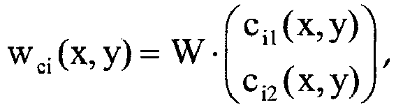 - wherein F(h 1, h 2,... hN ) is a master function that indicates an operation on the N describing functions hi(x,y), and wherein- the unit cell of the viewing grid is described by lattice cell vectors


 - the magnification terms Vi(x,y) are either scalars
 - the vectors (ci1(x,y), ci2(x,y)), where 0 ≤ c i1 (x, y), ci2 (x, y) < 1, indicate in each case, for the solid fi, the relative position of the center of the viewing elements within the cells i of the motif image,- the vectors (di1(x,y), di2(x,y)), where 0 ≤ di1 (x, y), di2 (x, y) < 1, each represent a displacement of the cell boundaries in the motif image, and- gi(x,y) are mask functions for adjusting the visibility of the solid fi. which are either identical to 1, or which define a strip-like or checkerboard-like alternation of the visibility of the solids fi.
 - A depiction arrangement for security papers, value documents, electronic display devices or other data carriers, having a raster image arrangement for depicting a plurality (N≥1) of specified three-dimensional solids that are each given by ni sections fij(x,y) and ni transparency step functions tij(x,y), where i=1,2,...N and j = 1,2,... ni, wherein, upon viewing with the eye separation being in the x-direction, the sections of the solid i each lie at a depth zij and wherein fij(x,y) is the image function of the j-th section of the i-th solid and indicates a brightness distribution, a color distribution, a binary distribution or another image properties, such as transparency, reflectivity, density or the like, and the transparency step function tij(x,y) is equal to 1 if, at the position (x,y), the section j of the solid i covers objects lying behind it, and otherwise is equal to 0, having- a motif image that is subdivided into a plurality of cells, in each of which are arranged imaged regions of the specified solids,- a viewing grid composed of a plurality of viewing elements for depicting the specified solids when the motif image is viewed with the aid of the viewing grid,- the motif image exhibiting, with its subdivision into a plurality of cells, an image function m(x,y) that is given by


 - wherein F(h 11 , h 12 ,...,h 1n
1 , h 21 ,h 22 ,...,h 2n2 ,...,h N1 ,h N2 ,...,hNnN ) is a master function that indicates an operation on the describing functions hij(x,y), and wherein- the unit cell of the viewing grid is described by lattice cell vectors


 - the magnification terms Vij are either scalars
 - the vectors (ci1(x,y), ci2(x,y)), where 0 ≤ c i1 (x, y), ci2 (x, y) < 1, indicate in each case, for the solid fi, the relative position of the center of the viewing elements within the cells i of the motif image,- the vectors (di1(x,y), di2(x,y)), where 0 ≤ di1 (x, y), di2 (x, y) < 1, each represent a displacement of the cell boundaries in the motif image, and- gi(x,y) are mask functions for adjusting the visibility of the solid fi. which are either identical to 1, or which define a strip-like or checkerboard-like alternation of the visibility of the solids fi.
 - The depiction arrangement according to one of claims 10 to 13, characterized in that at least one of the describing functions hi(x,y) or hij(x,y) is designed as specified in claims 1 to 7 for the image function m(x,y), and/or that the raster image arrangement depicts an alternating image, a motion image or a morph image, and/or that the master function F constitutes the sum function, and/or that two or more three-dimensional solids fi are visible simultaneously.
- The depiction arrangement according to at least one of claims 1 to 14, characterized in that the viewing grid and the motif image are firmly joined together to form a security element having a stacked, spaced-apart viewing grid and motif image, or that the viewing grid and the motif image are arranged at different positions of a data carrier such that the viewing grid and the motif image are stackable for self-authentication and form a security element in the stacked state, especially that the viewing grid and the motif image are stackable by bending, creasing, buckling or folding the data carrier.
- The depiction arrangement according to at least one of claims 1 to 15, characterized in that, to amplify the three-dimensional visual impression, the motif image is filled with Fresnel patterns, blaze lattices or other optically effective patterns, such as subwavelength patterns.
- The depiction arrangement according to at least one of claims 1 to 16, characterized in that after the determination of the image function m(x,y), the image contents of individual cells of the motif image are interchanged.
- The depiction arrangement according to at least one of claims 1 to 14 or 17, characterized in that the motif image is displayed by an electronic display device, and the viewing grid for viewing the displayed motif image is firmly joined with the electronic display device, or that the motif image is displayed by an electronic display device, and in that the viewing grid, as a separate viewing grid for viewing the displayed motif image, is bringable onto or in front of the electronic display device.
- A security paper for manufacturing security or value documents, such as banknotes, checks, identification cards, certificates or the like, having a depiction arrangement according to at least one of claims 1 to 17.
- A data carrier, especially a branded article, value document, decorative article or the like, having a depiction arrangement according to at least one of claims 1 to 17, wherein the viewing grid and/or the motif image of the depiction arrangement is preferably arranged in a window region of the data carrier.
- An electronic display arrangement having an electronic display device, especially a computer or television screen, a control device and a depiction arrangement according to at least one of claims 1 to 14 or 17 to 18, the control device being designed and adjusted to display the motif image of the depiction arrangement on the electronic display device.
Applications Claiming Priority (2)
| Application Number | Priority Date | Filing Date | Title |
|---|---|---|---|
| DE102007029204A DE102007029204A1 (en) | 2007-06-25 | 2007-06-25 | security element |
| PCT/EP2008/005171 WO2009000527A1 (en) | 2007-06-25 | 2008-06-25 | Representation system |
Publications (2)
| Publication Number | Publication Date |
|---|---|
| EP2164711A1 EP2164711A1 (en) | 2010-03-24 |
| EP2164711B1 true EP2164711B1 (en) | 2016-06-01 |
Family
ID=39929951
Family Applications (2)
| Application Number | Title | Priority Date | Filing Date |
|---|---|---|---|
| EP08759341.4A Active EP2164711B1 (en) | 2007-06-25 | 2008-06-25 | Representation system |
| EP08759342.2A Active EP2164713B1 (en) | 2007-06-25 | 2008-06-25 | Security element having a magnified, three-dimensional moiré image |
Family Applications After (1)
| Application Number | Title | Priority Date | Filing Date |
|---|---|---|---|
| EP08759342.2A Active EP2164713B1 (en) | 2007-06-25 | 2008-06-25 | Security element having a magnified, three-dimensional moiré image |
Country Status (7)
| Country | Link |
|---|---|
| US (2) | US8878844B2 (en) |
| EP (2) | EP2164711B1 (en) |
| CN (2) | CN101687427B (en) |
| AU (2) | AU2008267365B2 (en) |
| DE (1) | DE102007029204A1 (en) |
| RU (2) | RU2466030C2 (en) |
| WO (2) | WO2009000527A1 (en) |
Families Citing this family (96)
| Publication number | Priority date | Publication date | Assignee | Title |
|---|---|---|---|---|
| US8867134B2 (en) | 2003-11-21 | 2014-10-21 | Visual Physics, Llc | Optical system demonstrating improved resistance to optically degrading external effects |
| DE102005022018A1 (en) * | 2005-05-12 | 2006-11-16 | Giesecke & Devrient Gmbh | Security paper and process for its production |
| DE102005061749A1 (en) | 2005-12-21 | 2007-07-05 | Giesecke & Devrient Gmbh | Optically variable security element for making valuable objects safe has an achromatic reflecting micro-structure taking the form of a mosaic made from achromatic reflecting mosaic elements |
| DE102006058513A1 (en) | 2006-12-12 | 2008-06-19 | Giesecke & Devrient Gmbh | Drainage screen and process for its production |
| DE102007029204A1 (en) | 2007-06-25 | 2009-01-08 | Giesecke & Devrient Gmbh | security element |
| DE102007029203A1 (en) | 2007-06-25 | 2009-01-08 | Giesecke & Devrient Gmbh | security element |
| DE102007034716A1 (en) | 2007-07-23 | 2009-01-29 | Giesecke & Devrient Gmbh | security element |
| DE102007039591A1 (en) | 2007-08-22 | 2009-02-26 | Giesecke & Devrient Gmbh | grid image |
| DE102007061827A1 (en) * | 2007-12-20 | 2009-06-25 | Giesecke & Devrient Gmbh | Security element and method for its production |
| DE102007061828A1 (en) * | 2007-12-20 | 2009-06-25 | Giesecke & Devrient Gmbh | Security element and method for its production |
| DE102007062089A1 (en) | 2007-12-21 | 2009-07-02 | Giesecke & Devrient Gmbh | Method for creating a microstructure |
| DE102007061979A1 (en) | 2007-12-21 | 2009-06-25 | Giesecke & Devrient Gmbh | security element |
| DE102008008685A1 (en) * | 2008-02-12 | 2009-08-13 | Giesecke & Devrient Gmbh | Security element and method for its production |
| DE102008009296A1 (en) * | 2008-02-15 | 2009-08-20 | Giesecke & Devrient Gmbh | Security element and method for its production |
| DE102008013167A1 (en) | 2008-03-07 | 2009-09-10 | Giesecke & Devrient Gmbh | Security element and method for its production |
| DE102008016795A1 (en) | 2008-04-02 | 2009-10-08 | Giesecke & Devrient Gmbh | Method for producing a micro-optical moiré magnification arrangement |
| DE102008027952A1 (en) | 2008-06-12 | 2009-12-17 | Giesecke & Devrient Gmbh | Security element with screened layer of raster elements |
| DE102008028187A1 (en) * | 2008-06-12 | 2009-12-17 | Giesecke & Devrient Gmbh | Security element with optically variable element. |
| DE102008029638A1 (en) | 2008-06-23 | 2009-12-24 | Giesecke & Devrient Gmbh | security element |
| DE102008031325A1 (en) | 2008-07-02 | 2010-01-07 | Giesecke & Devrient Gmbh | Security element and method for its production |
| DE102008032224A1 (en) * | 2008-07-09 | 2010-01-14 | Giesecke & Devrient Gmbh | security element |
| DE102008046511A1 (en) | 2008-09-10 | 2010-03-11 | Giesecke & Devrient Gmbh | representation arrangement |
| DE102008053099A1 (en) | 2008-10-24 | 2010-04-29 | Giesecke & Devrient Gmbh | Security element with pressure-sensitive appearance |
| DE102008062475A1 (en) | 2008-12-16 | 2010-06-17 | Giesecke & Devrient Gmbh | Security element and security paper |
| EP2233314A1 (en) * | 2009-03-26 | 2010-09-29 | CSEM Centre Suisse d'Electronique et de Microtechnique SA - Recherche et Développement | Authentication item and system for packaged articles and method for the manufacturing of the authentication item |
| DE102009033221A1 (en) * | 2009-07-14 | 2011-01-27 | Human Bios Gmbh | Security element for marking or identification of objects and living beings |
| DE102009035413A1 (en) | 2009-07-31 | 2011-02-03 | Giesecke & Devrient Gmbh | Identification document with a personalized visual identification and method for its production |
| WO2011015384A1 (en) | 2009-08-04 | 2011-02-10 | Giesecke & Devrient Gmbh | Security arrangement |
| KR101758940B1 (en) | 2009-08-12 | 2017-07-17 | 비쥬얼 피직스 엘엘씨 | A tamper indicating optical security device |
| DE102009041583A1 (en) | 2009-09-15 | 2011-03-17 | Giesecke & Devrient Gmbh | Thin-film element with interference layer structure |
| DE102009042022A1 (en) | 2009-09-21 | 2011-03-24 | Giesecke & Devrient Gmbh | Elongated security element with machine-readable magnetic areas |
| DE102009056934A1 (en) | 2009-12-04 | 2011-06-09 | Giesecke & Devrient Gmbh | Security element, value document with such a security element and manufacturing method of a security element |
| DE102010047250A1 (en) | 2009-12-04 | 2011-06-09 | Giesecke & Devrient Gmbh | Security element, value document with such a security element and manufacturing method of a security element |
| GB201003397D0 (en) | 2010-03-01 | 2010-04-14 | Rue De Int Ltd | Moire magnification security device |
| GB2505724B (en) * | 2010-03-24 | 2015-10-14 | Securency Int Pty Ltd | Security document with integrated security device and method of manufacture |
| DE102010019766A1 (en) | 2010-05-07 | 2011-11-10 | Giesecke & Devrient Gmbh | Method for producing a microstructure on a support |
| DE102010025775A1 (en) | 2010-07-01 | 2012-01-05 | Giesecke & Devrient Gmbh | Security element and value document with such a security element |
| DE102010048262A1 (en) | 2010-10-12 | 2012-04-12 | Giesecke & Devrient Gmbh | presentation element |
| DE102010048772A1 (en) * | 2010-10-13 | 2012-04-19 | Bundesdruckerei Gmbh | A method of producing a security document having a viewing angle dependent security feature and security document |
| KR20120053430A (en) * | 2010-11-17 | 2012-05-25 | 삼성전자주식회사 | Device and method for providing image effect in wireless terminal |
| DE102010055689A1 (en) | 2010-12-22 | 2012-06-28 | Giesecke & Devrient Gmbh | Micro-optical viewing arrangement |
| CH701875A3 (en) | 2011-01-18 | 2011-11-30 | Trueb Ag | Method for producing a multilayer data carrier and data carrier produced by this method. |
| US8755121B2 (en) | 2011-01-28 | 2014-06-17 | Crane & Co., Inc. | Laser marked device |
| DE102011010127A1 (en) | 2011-02-02 | 2012-08-02 | Giesecke & Devrient Gmbh | Authenticity assurance of value documents by means of photochromic dyes |
| DE102011101635A1 (en) * | 2011-05-16 | 2012-11-22 | Giesecke & Devrient Gmbh | Two-dimensionally periodic, color-filtering grid |
| EP2726915A1 (en) | 2011-06-28 | 2014-05-07 | Visual Physics, LLC | Low curl or curl free optical film-to-paper laminate |
| DE102011108242A1 (en) | 2011-07-21 | 2013-01-24 | Giesecke & Devrient Gmbh | Optically variable element, in particular security element |
| CN104024921B (en) | 2011-08-19 | 2018-09-21 | 光学物理有限责任公司 | The optionally transferable optical system of thickness with reduction |
| DE102011112554A1 (en) * | 2011-09-06 | 2013-03-07 | Giesecke & Devrient Gmbh | Method for producing a security paper and microlens thread |
| ES2555952T5 (en) | 2011-09-26 | 2023-06-19 | Crane Security Tech Inc | Method for producing a composite band and security devices prepared from the composite band |
| DE102011114750A1 (en) | 2011-09-29 | 2013-04-04 | Giesecke & Devrient Gmbh | Process for producing a microstructure support |
| DE102011115125B4 (en) | 2011-10-07 | 2021-10-07 | Giesecke+Devrient Currency Technology Gmbh | Manufacture of a micro-optical display arrangement |
| BR112014009513A2 (en) * | 2011-10-19 | 2019-09-24 | Innovia Security Pity Ltd | Safety device |
| ES2814898T3 (en) | 2012-04-25 | 2021-03-29 | Visual Physics Llc | Security device for projecting a collection of synthetic images |
| DE102012008932A1 (en) | 2012-05-04 | 2013-11-07 | Giesecke & Devrient Gmbh | Value documents with protective coating and process for their production |
| WO2013188518A1 (en) | 2012-06-13 | 2013-12-19 | Visual Physics, Llc | Micro-optic material with improved abrasion resistance |
| RU2621558C9 (en) | 2012-08-17 | 2017-12-05 | Визуал Физикс, Ллс | Process of transfering microstructures on final substrate |
| JP6061552B2 (en) * | 2012-08-23 | 2017-01-18 | キヤノン株式会社 | Head-mounted image display device |
| US9132690B2 (en) * | 2012-09-05 | 2015-09-15 | Lumenco, Llc | Pixel mapping, arranging, and imaging for round and square-based micro lens arrays to achieve full volume 3D and multi-directional motion |
| NL2010045C2 (en) * | 2012-12-21 | 2014-06-24 | Morpho B V | Identity document comprising a ghost image based on a two- dimensional image. |
| KR102191322B1 (en) | 2013-03-15 | 2020-12-16 | 비쥬얼 피직스 엘엘씨 | Optical security device |
| RU2510689C1 (en) * | 2013-04-04 | 2014-04-10 | Федеральное Государственное Унитарное Предприятие "Гознак" (Фгуп "Гознак") | Multilayer polymer material with raster structure |
| US9873281B2 (en) | 2013-06-13 | 2018-01-23 | Visual Physics, Llc | Single layer image projection film |
| RU2528646C1 (en) * | 2013-06-28 | 2014-09-20 | Федеральное Государственное Унитарное Предприятие "Гознак" (Фгуп "Гознак") | Multilayer article having security element on surface of paper or polymer carrier, article authentication method |
| RU2528252C1 (en) | 2013-07-08 | 2014-09-10 | Федеральное Государственное Унитарное Предприятие "Гознак" (Фгуп "Гознак") | Multilayer document on paper or polymer substrate and method of determining its authenticity |
| CN103862997A (en) * | 2014-01-26 | 2014-06-18 | 张靖 | Decorating part with dynamic image effect |
| EP2908341B1 (en) * | 2014-02-18 | 2018-07-11 | ams AG | Semiconductor device with surface integrated focusing element |
| RU2573879C2 (en) * | 2014-03-18 | 2016-01-27 | Федеральное Государственное Унитарное Предприятие "Гознак" (Фгуп "Гознак") | Counterfeit-protected multilayer data medium |
| US10766292B2 (en) | 2014-03-27 | 2020-09-08 | Crane & Co., Inc. | Optical device that provides flicker-like optical effects |
| CA2943987A1 (en) | 2014-03-27 | 2015-10-01 | Visual Physics, Llc | An optical device that produces flicker-like optical effects |
| CN104118236B (en) * | 2014-07-10 | 2016-08-24 | 中钞特种防伪科技有限公司 | The micro-reflecting element array optical Security element of a kind of focusing and valuables |
| CN108749391B (en) | 2014-07-17 | 2021-05-11 | 光学物理有限责任公司 | Improved polymeric sheet for making polymeric security documents such as bank notes |
| CN104191860B (en) * | 2014-08-27 | 2016-06-22 | 苏州大学 | Colored dynamic solid moir é pattern thin film based on micro-printing and preparation method thereof |
| US10195890B2 (en) | 2014-09-16 | 2019-02-05 | Crane Security Technologies, Inc. | Secure lens layer |
| RU2596949C2 (en) * | 2014-09-18 | 2016-09-10 | Общество с ограниченной ответственностью "Полиграф-защита СПб" | Contact-droplet hgh printing method micro lenses on a flat information carrier and protective element on a flat carrier information |
| RU2596948C2 (en) * | 2014-09-18 | 2016-09-10 | Общество с ограниченной ответственностью "Полиграф-защита СПб" | Raster-moire optical system |
| JP6947358B2 (en) | 2015-02-11 | 2021-10-13 | クレイン アンド カンパニー、 インコーポレイテッド | How to attach the surface of the security device to the board |
| CN104773003B (en) * | 2015-04-17 | 2019-12-10 | 中钞油墨有限公司 | Printing stock printed with pattern for enhancing dynamic optical variation anti-counterfeiting effect and manufacturing method thereof |
| GB2539390B (en) * | 2015-06-10 | 2018-07-25 | De La Rue Int Ltd | Security devices and methods of manufacture thereof |
| MA42904A (en) | 2015-07-10 | 2018-05-16 | De La Rue Int Ltd | PROCESSES FOR MANUFACTURING SAFETY DOCUMENTS AND SAFETY DEVICES |
| DE102015218829B4 (en) * | 2015-09-30 | 2018-08-16 | Bayerische Motoren Werke Aktiengesellschaft | An image forming apparatus and method of making an array of imaging elements |
| US10189294B2 (en) * | 2015-12-03 | 2019-01-29 | Lumenco, Llc | Arrays of individually oriented micro mirrors for use in imaging security devices for currency and brand authentication |
| DE102016007784A1 (en) * | 2016-06-24 | 2017-12-28 | Giesecke+Devrient Currency Technology Gmbh | Optically variable security element |
| GB201612290D0 (en) * | 2016-07-15 | 2016-08-31 | La Rue Int De Ltd | Methods of manufacturing a secuirty device |
| DE102016221918A1 (en) | 2016-11-09 | 2018-05-09 | Bayerische Motoren Werke Aktiengesellschaft | Lighting device, in particular for a motor vehicle |
| KR102489526B1 (en) | 2017-02-10 | 2023-01-17 | 크레인 앤 코, 인크 | Machine-readable optical security device |
| EA030058B1 (en) * | 2017-03-15 | 2018-06-29 | Общество С Ограниченной Ответственностью "Центр Компьютерной Голографии" | Microoptical system for formation of visual images with kinematic motion effects |
| DE102017004585A1 (en) * | 2017-05-12 | 2018-11-15 | Giesecke+Devrient Currency Technology Gmbh | Security element with micro-reflectors |
| JP6804389B2 (en) * | 2017-05-30 | 2020-12-23 | 株式会社ニューフレアテクノロジー | Drawing device and drawing method |
| DE102017006421A1 (en) | 2017-07-07 | 2019-01-10 | Giesecke+Devrient Currency Technology Gmbh | Optically variable safety arrangement |
| KR20210029157A (en) | 2018-07-03 | 2021-03-15 | 크레인 앤 코, 인크 | Security document attached with security device showing increased harvesting resistance |
| RU188364U1 (en) * | 2018-08-01 | 2019-04-09 | Общество с Ограниченной Ответственностью (ООО) "МИДИ ПРИНТ" | STICKER |
| DE102018010078A1 (en) * | 2018-12-20 | 2020-06-25 | Giesecke+Devrient Currency Technology Gmbh | Optically variable security element |
| CN110133847B (en) * | 2019-04-29 | 2020-10-16 | 中国科学院光电技术研究所 | Design method for non-array dynamic display anti-counterfeiting pattern based on microstructure |
| EP3800061A1 (en) | 2019-10-03 | 2021-04-07 | Hueck Folien Gesellschaft m.b.H. | Security element with an optical effect layer |
| CN117677087A (en) * | 2022-08-25 | 2024-03-08 | 比亚迪股份有限公司 | Optical structure, terminal shell and terminal |
Family Cites Families (92)
| Publication number | Priority date | Publication date | Assignee | Title |
|---|---|---|---|---|
| US1475430A (en) | 1922-02-27 | 1923-11-27 | Curwen John Spedding | Advertising device or toy |
| DE3176833D1 (en) | 1980-11-05 | 1988-09-08 | Stephen Paul Mcgrew | Diffractive color and texture effects for the graphic arts |
| DE3687560D1 (en) * | 1985-10-15 | 1993-03-04 | Gao Ges Automation Org | DATA CARRIER WITH AN OPTICAL AUTHENTICITY CHARACTER, AND METHOD FOR PRODUCING AND CHECKING THE DATA CARRIER. |
| DE3602563C1 (en) | 1986-01-29 | 1987-04-16 | Deutsche Bundesbank | Security paper with optically active structures generating a moiré effect |
| DE3609090A1 (en) | 1986-03-18 | 1987-09-24 | Gao Ges Automation Org | SECURITY PAPER WITH SECURED THREAD STORED IN IT AND METHOD FOR THE PRODUCTION THEREOF |
| WO1989008166A1 (en) | 1988-03-04 | 1989-09-08 | GAO GESELLSCHAFT FÜR AUTOMATION UND ORGANISATION m | Security element in the form of a thread or a ribbon for insertion in security documents, and process for producing it |
| GB9309673D0 (en) | 1993-05-11 | 1993-06-23 | De La Rue Holographics Ltd | Security device |
| JP2761861B2 (en) * | 1996-02-06 | 1998-06-04 | 明和グラビア株式会社 | Decorative sheet |
| JP3338860B2 (en) | 1996-07-17 | 2002-10-28 | ヤマックス株式会社 | Decorative pattern |
| US5772250A (en) | 1997-04-11 | 1998-06-30 | Eastman Kodak Company | Copy restrictive color-reversal documents |
| DE19739193B4 (en) | 1997-09-08 | 2006-08-03 | Giesecke & Devrient Gmbh | Method for producing security films for securities |
| JP3131771B2 (en) | 1997-12-26 | 2001-02-05 | 明和グラビア株式会社 | Decorative sheet with three-dimensional effect |
| US6483644B1 (en) | 1998-08-07 | 2002-11-19 | Phil Gottfried | Integral image, method and device |
| JP3505617B2 (en) | 1999-06-09 | 2004-03-08 | ヤマックス株式会社 | Virtual image appearance decoration |
| DE19949542C2 (en) | 1999-10-14 | 2002-07-11 | Orga Kartensysteme Gmbh | Process for the production of micro-writing on data carriers, in particular plastic cards |
| US6288842B1 (en) | 2000-02-22 | 2001-09-11 | 3M Innovative Properties | Sheeting with composite image that floats |
| US7068434B2 (en) | 2000-02-22 | 2006-06-27 | 3M Innovative Properties Company | Sheeting with composite image that floats |
| GB2362493B (en) * | 2000-04-04 | 2004-05-12 | Floating Images Ltd | Advertising hoarding,billboard or poster with high visual impact |
| US6450540B1 (en) * | 2000-11-15 | 2002-09-17 | Technology Tree Co., Ltd | Printed matter displaying various colors according to view angle |
| JP2003039583A (en) * | 2001-07-27 | 2003-02-13 | Meiwa Gravure Co Ltd | Decorative sheet |
| JP2003120500A (en) | 2001-10-10 | 2003-04-23 | Maeda Seikan Kk | Wind mill with vertical axis having guide plate for small power |
| US7751608B2 (en) | 2004-06-30 | 2010-07-06 | Ecole Polytechnique Federale De Lausanne (Epfl) | Model-based synthesis of band moire images for authenticating security documents and valuable products |
| US7194105B2 (en) | 2002-10-16 | 2007-03-20 | Hersch Roger D | Authentication of documents and articles by moiré patterns |
| DE10254500B4 (en) * | 2002-11-22 | 2006-03-16 | Ovd Kinegram Ag | Optically variable element and its use |
| DE10325146A1 (en) | 2003-05-30 | 2004-12-16 | X3D Technologies Gmbh | Method and arrangement for spatial representation |
| EP2284018B1 (en) | 2003-11-21 | 2021-05-19 | Visual Physics, LLC | Micro-optic security and image presentation system |
| DE102004007379B3 (en) * | 2004-02-16 | 2005-09-01 | Ovd Kinegram Ag | Valuable object with moiré pattern |
| DE102004039355A1 (en) | 2004-08-12 | 2006-02-23 | Giesecke & Devrient Gmbh | Security element and method for its production |
| WO2005108108A2 (en) | 2004-04-30 | 2005-11-17 | Giesecke & Devrient Gmbh | Security element and methods for the production thereof |
| WO2005106601A2 (en) | 2004-04-30 | 2005-11-10 | De La Rue International Limited | Arrays of microlenses and arrays of microimages on transparent security substrates |
| WO2005105475A1 (en) | 2004-04-30 | 2005-11-10 | Giesecke & Devrient Gmbh | Sheeting and methods for the production thereof |
| DE102004021247A1 (en) | 2004-04-30 | 2005-11-24 | Giesecke & Devrient Gmbh | Security element and method for its production |
| DE102004021246A1 (en) | 2004-04-30 | 2005-11-24 | Giesecke & Devrient Gmbh | Security element and method for its production |
| DE102004022080A1 (en) | 2004-05-05 | 2005-11-24 | Giesecke & Devrient Gmbh | Value document with visually recognizable markings |
| DE102004022079A1 (en) | 2004-05-05 | 2005-11-24 | Giesecke & Devrient Gmbh | Value document with serial number |
| DE102004031879B4 (en) | 2004-06-30 | 2017-11-02 | Ovd Kinegram Ag | Security document for RF identification |
| DE102004035979A1 (en) | 2004-07-14 | 2006-02-02 | Giesecke & Devrient Gmbh | Security element and method for its production |
| DE102004038542A1 (en) | 2004-08-06 | 2006-02-23 | Giesecke & Devrient Gmbh | Data carrier with security element and method for its production |
| BRPI0515003A (en) | 2004-08-12 | 2008-07-01 | Giesecke & Devrient Gmbh | security element containing a substrate |
| DE102004044459B4 (en) * | 2004-09-15 | 2009-07-09 | Ovd Kinegram Ag | Security document with transparent windows |
| DE102004049118A1 (en) | 2004-10-07 | 2006-04-13 | Giesecke & Devrient Gmbh | Security element and method for its production |
| DE102004056553B4 (en) | 2004-11-23 | 2013-03-14 | Giesecke & Devrient Gmbh | Security arrangement for security documents and method for producing the security documents |
| DE102004059798A1 (en) * | 2004-12-10 | 2006-06-29 | Ovd Kinegram Ag | Optically variable element with electrically active layer |
| DE102004063217A1 (en) | 2004-12-29 | 2006-07-13 | Giesecke & Devrient Gmbh | Security feature for value documents |
| DE102005028162A1 (en) * | 2005-02-18 | 2006-12-28 | Giesecke & Devrient Gmbh | Security element for protecting valuable objects, e.g. documents, includes focusing components for enlarging views of microscopic structures as one of two authenication features |
| DE102005045566A1 (en) | 2005-03-23 | 2006-09-28 | Giesecke & Devrient Gmbh | Multi-layer security paper |
| DE102005022018A1 (en) | 2005-05-12 | 2006-11-16 | Giesecke & Devrient Gmbh | Security paper and process for its production |
| ES2644361T3 (en) * | 2005-05-18 | 2017-11-28 | Visual Physics, Llc | Imaging system and micro-optical security |
| DE102005025095A1 (en) | 2005-06-01 | 2006-12-07 | Giesecke & Devrient Gmbh | Data carrier and method for its production |
| TWI376318B (en) * | 2005-07-12 | 2012-11-11 | Grapac Japan Co Inc | Stereoscopic sheet composition |
| DE102005032815A1 (en) | 2005-07-12 | 2007-01-18 | Giesecke & Devrient Gmbh | Method for producing a security paper, paper screen and forming element for paper screen |
| DE102005032997A1 (en) | 2005-07-14 | 2007-01-18 | Giesecke & Devrient Gmbh | Lattice image and method for its production |
| US7487915B2 (en) | 2005-09-09 | 2009-02-10 | Graphic Security Systems Corporation | Reflective decoders for use in decoding optically encoded images |
| DE102005052562A1 (en) | 2005-11-02 | 2007-05-03 | Giesecke & Devrient Gmbh | Method for production of safety element with optically variable structure, involves providing substrate with marking structure with many flat markings and relief structure with many reflex relief elements |
| DE102005061749A1 (en) | 2005-12-21 | 2007-07-05 | Giesecke & Devrient Gmbh | Optically variable security element for making valuable objects safe has an achromatic reflecting micro-structure taking the form of a mosaic made from achromatic reflecting mosaic elements |
| DE102005062132A1 (en) | 2005-12-23 | 2007-07-05 | Giesecke & Devrient Gmbh | Security unit e.g. seal, for e.g. valuable document, has motive image with planar periodic arrangement of micro motive units, and periodic arrangement of lens for moire magnified observation of motive units |
| DE102006005000B4 (en) | 2006-02-01 | 2016-05-04 | Ovd Kinegram Ag | Multi-layer body with microlens arrangement |
| DE102006006501A1 (en) | 2006-02-13 | 2007-08-16 | Giesecke & Devrient Gmbh | Security element with an optically variable structure |
| DE102006015023A1 (en) | 2006-03-31 | 2007-10-04 | Giesecke & Devrient Gmbh | Security element for security papers, value documents, has relief structure, which is formed on basis of cholesteric, liquid crystalline polymer material and top layer contains reflecting or high-refracting layer |
| DE102006023084B4 (en) | 2006-05-16 | 2019-07-18 | Leonhard Kurz Stiftung & Co. Kg | Value document with security element |
| DE102006029536B4 (en) | 2006-06-26 | 2011-05-05 | Ovd Kinegram Ag | Multi-layer body with microlenses and process for its preparation |
| DE102006029850A1 (en) | 2006-06-27 | 2008-01-03 | Giesecke & Devrient Gmbh | security element |
| DE102006029852A1 (en) | 2006-06-27 | 2008-01-03 | Giesecke & Devrient Gmbh | Method of applying a microstructure, mold and microstructured article |
| WO2008008635A2 (en) | 2006-06-28 | 2008-01-17 | Visual Physics, Llc | Micro-optic security and image presentation system |
| DE102006039305A1 (en) | 2006-07-21 | 2008-01-24 | Giesecke & Devrient Gmbh | Security thread with optically variable security feature |
| DE102006050047A1 (en) | 2006-10-24 | 2008-04-30 | Giesecke & Devrient Gmbh | Transparent security element for security papers, data carrier, particularly valuable documents such as bank note, identification card and for falsification of goods, has transparent substrate and marking layer applied on substrate |
| DE102006055680A1 (en) | 2006-11-23 | 2008-05-29 | Giesecke & Devrient Gmbh | Security element with metallization |
| DE102006058513A1 (en) | 2006-12-12 | 2008-06-19 | Giesecke & Devrient Gmbh | Drainage screen and process for its production |
| DE102007005414A1 (en) | 2007-01-30 | 2008-08-07 | Ovd Kinegram Ag | Security element for securing value documents |
| DE102007029203A1 (en) | 2007-06-25 | 2009-01-08 | Giesecke & Devrient Gmbh | security element |
| DE102007029204A1 (en) | 2007-06-25 | 2009-01-08 | Giesecke & Devrient Gmbh | security element |
| DE102007034716A1 (en) | 2007-07-23 | 2009-01-29 | Giesecke & Devrient Gmbh | security element |
| DE102007039591A1 (en) | 2007-08-22 | 2009-02-26 | Giesecke & Devrient Gmbh | grid image |
| RU2432262C1 (en) * | 2007-09-03 | 2011-10-27 | Нэшнл Принтинг Бюро, Инкорпорейтед Эдминистрейтив Эдженси | Printed document with counterfeit protection |
| DE102007061828A1 (en) | 2007-12-20 | 2009-06-25 | Giesecke & Devrient Gmbh | Security element and method for its production |
| DE102007061827A1 (en) | 2007-12-20 | 2009-06-25 | Giesecke & Devrient Gmbh | Security element and method for its production |
| DE102007062089A1 (en) | 2007-12-21 | 2009-07-02 | Giesecke & Devrient Gmbh | Method for creating a microstructure |
| DE102007061979A1 (en) | 2007-12-21 | 2009-06-25 | Giesecke & Devrient Gmbh | security element |
| DE102008008685A1 (en) | 2008-02-12 | 2009-08-13 | Giesecke & Devrient Gmbh | Security element and method for its production |
| US8408353B2 (en) | 2008-02-12 | 2013-04-02 | Jtekt Corporation | Vehicle steering apparatus |
| DE102008009296A1 (en) | 2008-02-15 | 2009-08-20 | Giesecke & Devrient Gmbh | Security element and method for its production |
| DE102008013167A1 (en) | 2008-03-07 | 2009-09-10 | Giesecke & Devrient Gmbh | Security element and method for its production |
| DE102008016795A1 (en) | 2008-04-02 | 2009-10-08 | Giesecke & Devrient Gmbh | Method for producing a micro-optical moiré magnification arrangement |
| DE102008028187A1 (en) | 2008-06-12 | 2009-12-17 | Giesecke & Devrient Gmbh | Security element with optically variable element. |
| DE102008027952A1 (en) | 2008-06-12 | 2009-12-17 | Giesecke & Devrient Gmbh | Security element with screened layer of raster elements |
| DE102008029638A1 (en) | 2008-06-23 | 2009-12-24 | Giesecke & Devrient Gmbh | security element |
| DE102008031325A1 (en) | 2008-07-02 | 2010-01-07 | Giesecke & Devrient Gmbh | Security element and method for its production |
| DE102008032224A1 (en) | 2008-07-09 | 2010-01-14 | Giesecke & Devrient Gmbh | security element |
| DE102008046511A1 (en) | 2008-09-10 | 2010-03-11 | Giesecke & Devrient Gmbh | representation arrangement |
| DE102009035413A1 (en) | 2009-07-31 | 2011-02-03 | Giesecke & Devrient Gmbh | Identification document with a personalized visual identification and method for its production |
| DE102009041583A1 (en) | 2009-09-15 | 2011-03-17 | Giesecke & Devrient Gmbh | Thin-film element with interference layer structure |
| DE102009042022A1 (en) | 2009-09-21 | 2011-03-24 | Giesecke & Devrient Gmbh | Elongated security element with machine-readable magnetic areas |
-
2007
- 2007-06-25 DE DE102007029204A patent/DE102007029204A1/en not_active Withdrawn
-
2008
- 2008-06-25 CN CN2008800218663A patent/CN101687427B/en active Active
- 2008-06-25 EP EP08759341.4A patent/EP2164711B1/en active Active
- 2008-06-25 CN CN2008800218678A patent/CN101711203B/en active Active
- 2008-06-25 WO PCT/EP2008/005171 patent/WO2009000527A1/en active Search and Examination
- 2008-06-25 AU AU2008267365A patent/AU2008267365B2/en active Active
- 2008-06-25 US US12/665,843 patent/US8878844B2/en active Active
- 2008-06-25 US US12/665,834 patent/US8400495B2/en active Active
- 2008-06-25 AU AU2008267368A patent/AU2008267368B2/en active Active
- 2008-06-25 EP EP08759342.2A patent/EP2164713B1/en active Active
- 2008-06-25 WO PCT/EP2008/005174 patent/WO2009000530A2/en active Application Filing
- 2008-06-25 RU RU2010101423/12A patent/RU2466030C2/en active
- 2008-06-25 RU RU2010101424/12A patent/RU2466875C2/en active
Also Published As
| Publication number | Publication date |
|---|---|
| CN101711203B (en) | 2013-03-13 |
| EP2164711A1 (en) | 2010-03-24 |
| AU2008267365A1 (en) | 2008-12-31 |
| CN101687427A (en) | 2010-03-31 |
| RU2010101423A (en) | 2011-07-27 |
| RU2466030C2 (en) | 2012-11-10 |
| EP2164713B1 (en) | 2016-04-06 |
| AU2008267368A1 (en) | 2008-12-31 |
| CN101711203A (en) | 2010-05-19 |
| US8878844B2 (en) | 2014-11-04 |
| WO2009000530A2 (en) | 2008-12-31 |
| AU2008267365B2 (en) | 2013-04-04 |
| DE102007029204A1 (en) | 2009-01-08 |
| CN101687427B (en) | 2012-01-18 |
| WO2009000530A3 (en) | 2009-04-30 |
| US8400495B2 (en) | 2013-03-19 |
| EP2164713A2 (en) | 2010-03-24 |
| RU2010101424A (en) | 2011-07-27 |
| US20100208036A1 (en) | 2010-08-19 |
| US20100177094A1 (en) | 2010-07-15 |
| RU2466875C2 (en) | 2012-11-20 |
| AU2008267368B2 (en) | 2013-04-18 |
| WO2009000527A1 (en) | 2008-12-31 |
Similar Documents
| Publication | Publication Date | Title |
|---|---|---|
| EP2164711B1 (en) | Representation system | |
| EP2164712B1 (en) | Representation system | |
| EP2331343B1 (en) | Representation system | |
| EP1965990B1 (en) | Security element | |
| EP2435254B1 (en) | Security element, security system, and production method therefor | |
| EP3216620B1 (en) | Security element, valuable document comprising such a security element and method for producing such a security element | |
| EP2627520B1 (en) | Representation element comprising optical elements arranged on a substrate, for producing an image composed of light spots and suspended above or below the substrate | |
| EP3000613B1 (en) | Optically variable security element having reflective surface area | |
| DE112017001373T5 (en) | Micro-optical device with double-sided optical effect | |
| EP2934904B1 (en) | Security element with a lenticular image | |
| DE112017001245T5 (en) | Micro-optical device with structure with integrated focusing element and picture element | |
| EP2385902B1 (en) | Security element and security paper | |
| EP2727742B1 (en) | Security element with lenticular image | |
| EP3184318A1 (en) | Optically variable security element having reflective surface area | |
| EP3621819A1 (en) | Security element having a micromirror arrangement for producing an optically variable effect and production method for the security element | |
| DE102010053679B4 (en) | Security element for card-shaped data carriers and method for its production | |
| DE102009004251B3 (en) | Security element and method for producing a security element | |
| DE112020005501T5 (en) | Micro-optical device |
Legal Events
| Date | Code | Title | Description |
|---|---|---|---|
| PUAI | Public reference made under article 153(3) epc to a published international application that has entered the european phase |
Free format text: ORIGINAL CODE: 0009012 |
|
| 17P | Request for examination filed |
Effective date: 20100125 |
|
| AK | Designated contracting states |
Kind code of ref document: A1 Designated state(s): AT BE BG CH CY CZ DE DK EE ES FI FR GB GR HR HU IE IS IT LI LT LU LV MC MT NL NO PL PT RO SE SI SK TR |
|
| AX | Request for extension of the european patent |
Extension state: AL BA MK RS |
|
| RIN1 | Information on inventor provided before grant (corrected) |
Inventor name: KAULE, WITTICH Inventor name: RAHM, MICHAEL Inventor name: RAUSCHER, WOLFGANG |
|
| DAX | Request for extension of the european patent (deleted) | ||
| 17Q | First examination report despatched |
Effective date: 20140307 |
|
| REG | Reference to a national code |
Ref country code: DE Ref legal event code: R079 Ref document number: 502008014268 Country of ref document: DE Free format text: PREVIOUS MAIN CLASS: B42D0015000000 Ipc: B42D0025324000 |
|
| GRAP | Despatch of communication of intention to grant a patent |
Free format text: ORIGINAL CODE: EPIDOSNIGR1 |
|
| RIC1 | Information provided on ipc code assigned before grant |
Ipc: B42D 25/342 20140101ALI20151126BHEP Ipc: B42D 25/324 20140101AFI20151126BHEP |
|
| INTG | Intention to grant announced |
Effective date: 20151218 |
|
| GRAS | Grant fee paid |
Free format text: ORIGINAL CODE: EPIDOSNIGR3 |
|
| GRAA | (expected) grant |
Free format text: ORIGINAL CODE: 0009210 |
|
| AK | Designated contracting states |
Kind code of ref document: B1 Designated state(s): AT BE BG CH CY CZ DE DK EE ES FI FR GB GR HR HU IE IS IT LI LT LU LV MC MT NL NO PL PT RO SE SI SK TR |
|
| REG | Reference to a national code |
Ref country code: GB Ref legal event code: FG4D Free format text: NOT ENGLISH |
|
| REG | Reference to a national code |
Ref country code: CH Ref legal event code: EP Ref country code: AT Ref legal event code: REF Ref document number: 803643 Country of ref document: AT Kind code of ref document: T Effective date: 20160615 |
|
| REG | Reference to a national code |
Ref country code: IE Ref legal event code: FG4D Free format text: LANGUAGE OF EP DOCUMENT: GERMAN |
|
| REG | Reference to a national code |
Ref country code: DE Ref legal event code: R096 Ref document number: 502008014268 Country of ref document: DE |
|
| REG | Reference to a national code |
Ref country code: CH Ref legal event code: NV Representative=s name: RENTSCH PARTNER AG, CH |
|
| REG | Reference to a national code |
Ref country code: FR Ref legal event code: PLFP Year of fee payment: 9 |
|
| REG | Reference to a national code |
Ref country code: SE Ref legal event code: TRGR |
|
| REG | Reference to a national code |
Ref country code: LT Ref legal event code: MG4D |
|
| REG | Reference to a national code |
Ref country code: NL Ref legal event code: MP Effective date: 20160601 |
|
| PG25 | Lapsed in a contracting state [announced via postgrant information from national office to epo] |
Ref country code: NO Free format text: LAPSE BECAUSE OF FAILURE TO SUBMIT A TRANSLATION OF THE DESCRIPTION OR TO PAY THE FEE WITHIN THE PRESCRIBED TIME-LIMIT Effective date: 20160901 Ref country code: LT Free format text: LAPSE BECAUSE OF FAILURE TO SUBMIT A TRANSLATION OF THE DESCRIPTION OR TO PAY THE FEE WITHIN THE PRESCRIBED TIME-LIMIT Effective date: 20160601 Ref country code: FI Free format text: LAPSE BECAUSE OF FAILURE TO SUBMIT A TRANSLATION OF THE DESCRIPTION OR TO PAY THE FEE WITHIN THE PRESCRIBED TIME-LIMIT Effective date: 20160601 |
|
| PG25 | Lapsed in a contracting state [announced via postgrant information from national office to epo] |
Ref country code: LV Free format text: LAPSE BECAUSE OF FAILURE TO SUBMIT A TRANSLATION OF THE DESCRIPTION OR TO PAY THE FEE WITHIN THE PRESCRIBED TIME-LIMIT Effective date: 20160601 Ref country code: NL Free format text: LAPSE BECAUSE OF FAILURE TO SUBMIT A TRANSLATION OF THE DESCRIPTION OR TO PAY THE FEE WITHIN THE PRESCRIBED TIME-LIMIT Effective date: 20160601 Ref country code: GR Free format text: LAPSE BECAUSE OF FAILURE TO SUBMIT A TRANSLATION OF THE DESCRIPTION OR TO PAY THE FEE WITHIN THE PRESCRIBED TIME-LIMIT Effective date: 20160902 Ref country code: ES Free format text: LAPSE BECAUSE OF FAILURE TO SUBMIT A TRANSLATION OF THE DESCRIPTION OR TO PAY THE FEE WITHIN THE PRESCRIBED TIME-LIMIT Effective date: 20160601 Ref country code: HR Free format text: LAPSE BECAUSE OF FAILURE TO SUBMIT A TRANSLATION OF THE DESCRIPTION OR TO PAY THE FEE WITHIN THE PRESCRIBED TIME-LIMIT Effective date: 20160601 |
|
| PG25 | Lapsed in a contracting state [announced via postgrant information from national office to epo] |
Ref country code: BE Free format text: LAPSE BECAUSE OF NON-PAYMENT OF DUE FEES Effective date: 20160630 |
|
| PG25 | Lapsed in a contracting state [announced via postgrant information from national office to epo] |
Ref country code: SK Free format text: LAPSE BECAUSE OF FAILURE TO SUBMIT A TRANSLATION OF THE DESCRIPTION OR TO PAY THE FEE WITHIN THE PRESCRIBED TIME-LIMIT Effective date: 20160601 Ref country code: EE Free format text: LAPSE BECAUSE OF FAILURE TO SUBMIT A TRANSLATION OF THE DESCRIPTION OR TO PAY THE FEE WITHIN THE PRESCRIBED TIME-LIMIT Effective date: 20160601 Ref country code: IS Free format text: LAPSE BECAUSE OF FAILURE TO SUBMIT A TRANSLATION OF THE DESCRIPTION OR TO PAY THE FEE WITHIN THE PRESCRIBED TIME-LIMIT Effective date: 20161001 Ref country code: RO Free format text: LAPSE BECAUSE OF FAILURE TO SUBMIT A TRANSLATION OF THE DESCRIPTION OR TO PAY THE FEE WITHIN THE PRESCRIBED TIME-LIMIT Effective date: 20160601 Ref country code: CZ Free format text: LAPSE BECAUSE OF FAILURE TO SUBMIT A TRANSLATION OF THE DESCRIPTION OR TO PAY THE FEE WITHIN THE PRESCRIBED TIME-LIMIT Effective date: 20160601 |
|
| PG25 | Lapsed in a contracting state [announced via postgrant information from national office to epo] |
Ref country code: PT Free format text: LAPSE BECAUSE OF FAILURE TO SUBMIT A TRANSLATION OF THE DESCRIPTION OR TO PAY THE FEE WITHIN THE PRESCRIBED TIME-LIMIT Effective date: 20161003 Ref country code: PL Free format text: LAPSE BECAUSE OF FAILURE TO SUBMIT A TRANSLATION OF THE DESCRIPTION OR TO PAY THE FEE WITHIN THE PRESCRIBED TIME-LIMIT Effective date: 20160601 |
|
| REG | Reference to a national code |
Ref country code: DE Ref legal event code: R097 Ref document number: 502008014268 Country of ref document: DE |
|
| REG | Reference to a national code |
Ref country code: IE Ref legal event code: MM4A |
|
| PG25 | Lapsed in a contracting state [announced via postgrant information from national office to epo] |
Ref country code: MC Free format text: LAPSE BECAUSE OF FAILURE TO SUBMIT A TRANSLATION OF THE DESCRIPTION OR TO PAY THE FEE WITHIN THE PRESCRIBED TIME-LIMIT Effective date: 20160601 |
|
| PLBE | No opposition filed within time limit |
Free format text: ORIGINAL CODE: 0009261 |
|
| STAA | Information on the status of an ep patent application or granted ep patent |
Free format text: STATUS: NO OPPOSITION FILED WITHIN TIME LIMIT |
|
| 26N | No opposition filed |
Effective date: 20170302 |
|
| PG25 | Lapsed in a contracting state [announced via postgrant information from national office to epo] |
Ref country code: SI Free format text: LAPSE BECAUSE OF FAILURE TO SUBMIT A TRANSLATION OF THE DESCRIPTION OR TO PAY THE FEE WITHIN THE PRESCRIBED TIME-LIMIT Effective date: 20160601 Ref country code: IE Free format text: LAPSE BECAUSE OF NON-PAYMENT OF DUE FEES Effective date: 20160625 Ref country code: DK Free format text: LAPSE BECAUSE OF FAILURE TO SUBMIT A TRANSLATION OF THE DESCRIPTION OR TO PAY THE FEE WITHIN THE PRESCRIBED TIME-LIMIT Effective date: 20160601 |
|
| REG | Reference to a national code |
Ref country code: FR Ref legal event code: PLFP Year of fee payment: 10 |
|
| REG | Reference to a national code |
Ref country code: DE Ref legal event code: R081 Ref document number: 502008014268 Country of ref document: DE Owner name: GIESECKE+DEVRIENT CURRENCY TECHNOLOGY GMBH, DE Free format text: FORMER OWNER: GIESECKE & DEVRIENT GMBH, 81677 MUENCHEN, DE |
|
| REG | Reference to a national code |
Ref country code: CH Ref legal event code: PCAR Free format text: NEW ADDRESS: BELLERIVESTRASSE 203 POSTFACH, 8034 ZUERICH (CH) |
|
| REG | Reference to a national code |
Ref country code: CH Ref legal event code: PUE Owner name: GIESECKE+DEVRIENT CURRENCY TECHNOLOGY GMBH, DE Free format text: FORMER OWNER: GIESECKE AND DEVRIENT GMBH, DE |
|
| REG | Reference to a national code |
Ref country code: GB Ref legal event code: 732E Free format text: REGISTERED BETWEEN 20180118 AND 20180124 |
|
| PG25 | Lapsed in a contracting state [announced via postgrant information from national office to epo] |
Ref country code: HU Free format text: LAPSE BECAUSE OF FAILURE TO SUBMIT A TRANSLATION OF THE DESCRIPTION OR TO PAY THE FEE WITHIN THE PRESCRIBED TIME-LIMIT; INVALID AB INITIO Effective date: 20080625 Ref country code: CY Free format text: LAPSE BECAUSE OF FAILURE TO SUBMIT A TRANSLATION OF THE DESCRIPTION OR TO PAY THE FEE WITHIN THE PRESCRIBED TIME-LIMIT Effective date: 20160601 |
|
| REG | Reference to a national code |
Ref country code: AT Ref legal event code: PC Ref document number: 803643 Country of ref document: AT Kind code of ref document: T Owner name: GIESECKE+DEVRIENT CURRENCY TECHNOLOGY GMBH, DE Effective date: 20180426 |
|
| REG | Reference to a national code |
Ref country code: FR Ref legal event code: PLFP Year of fee payment: 11 |
|
| PG25 | Lapsed in a contracting state [announced via postgrant information from national office to epo] |
Ref country code: MT Free format text: LAPSE BECAUSE OF FAILURE TO SUBMIT A TRANSLATION OF THE DESCRIPTION OR TO PAY THE FEE WITHIN THE PRESCRIBED TIME-LIMIT Effective date: 20160601 Ref country code: TR Free format text: LAPSE BECAUSE OF FAILURE TO SUBMIT A TRANSLATION OF THE DESCRIPTION OR TO PAY THE FEE WITHIN THE PRESCRIBED TIME-LIMIT Effective date: 20160601 Ref country code: LU Free format text: LAPSE BECAUSE OF NON-PAYMENT OF DUE FEES Effective date: 20160625 |
|
| REG | Reference to a national code |
Ref country code: FR Ref legal event code: TP Owner name: GIESECKE+DEVRIENT CURRENCY TECHNOLOGY GMBH, DE Effective date: 20180530 |
|
| PG25 | Lapsed in a contracting state [announced via postgrant information from national office to epo] |
Ref country code: BG Free format text: LAPSE BECAUSE OF FAILURE TO SUBMIT A TRANSLATION OF THE DESCRIPTION OR TO PAY THE FEE WITHIN THE PRESCRIBED TIME-LIMIT Effective date: 20160601 |
|
| PGFP | Annual fee paid to national office [announced via postgrant information from national office to epo] |
Ref country code: SE Payment date: 20190624 Year of fee payment: 12 |
|
| PG25 | Lapsed in a contracting state [announced via postgrant information from national office to epo] |
Ref country code: SE Free format text: LAPSE BECAUSE OF NON-PAYMENT OF DUE FEES Effective date: 20200626 |
|
| REG | Reference to a national code |
Ref country code: SE Ref legal event code: EUG |
|
| P01 | Opt-out of the competence of the unified patent court (upc) registered |
Effective date: 20230520 |
|
| PGFP | Annual fee paid to national office [announced via postgrant information from national office to epo] |
Ref country code: IT Payment date: 20230630 Year of fee payment: 16 Ref country code: CH Payment date: 20230702 Year of fee payment: 16 |
|
| PGFP | Annual fee paid to national office [announced via postgrant information from national office to epo] |
Ref country code: GB Payment date: 20240620 Year of fee payment: 17 |
|
| PGFP | Annual fee paid to national office [announced via postgrant information from national office to epo] |
Ref country code: DE Payment date: 20240630 Year of fee payment: 17 |
|
| PGFP | Annual fee paid to national office [announced via postgrant information from national office to epo] |
Ref country code: AT Payment date: 20240617 Year of fee payment: 17 |
|
| PGFP | Annual fee paid to national office [announced via postgrant information from national office to epo] |
Ref country code: FR Payment date: 20240621 Year of fee payment: 17 |