WO2008062503A1 - Lentille de contact et son procédé de fabrication - Google Patents
Lentille de contact et son procédé de fabrication Download PDFInfo
- Publication number
- WO2008062503A1 WO2008062503A1 PCT/JP2006/323120 JP2006323120W WO2008062503A1 WO 2008062503 A1 WO2008062503 A1 WO 2008062503A1 JP 2006323120 W JP2006323120 W JP 2006323120W WO 2008062503 A1 WO2008062503 A1 WO 2008062503A1
- Authority
- WO
- WIPO (PCT)
- Prior art keywords
- optical
- contact lens
- thickness
- lens
- manufacturing
- Prior art date
Links
Classifications
-
- G—PHYSICS
- G02—OPTICS
- G02C—SPECTACLES; SUNGLASSES OR GOGGLES INSOFAR AS THEY HAVE THE SAME FEATURES AS SPECTACLES; CONTACT LENSES
- G02C7/00—Optical parts
- G02C7/02—Lenses; Lens systems ; Methods of designing lenses
- G02C7/04—Contact lenses for the eyes
-
- B—PERFORMING OPERATIONS; TRANSPORTING
- B29—WORKING OF PLASTICS; WORKING OF SUBSTANCES IN A PLASTIC STATE IN GENERAL
- B29D—PRODUCING PARTICULAR ARTICLES FROM PLASTICS OR FROM SUBSTANCES IN A PLASTIC STATE
- B29D11/00—Producing optical elements, e.g. lenses or prisms
- B29D11/00009—Production of simple or compound lenses
- B29D11/00038—Production of contact lenses
-
- G—PHYSICS
- G02—OPTICS
- G02C—SPECTACLES; SUNGLASSES OR GOGGLES INSOFAR AS THEY HAVE THE SAME FEATURES AS SPECTACLES; CONTACT LENSES
- G02C7/00—Optical parts
- G02C7/02—Lenses; Lens systems ; Methods of designing lenses
- G02C7/04—Contact lenses for the eyes
- G02C7/047—Contact lens fitting; Contact lenses for orthokeratology; Contact lenses for specially shaped corneae
-
- G—PHYSICS
- G02—OPTICS
- G02C—SPECTACLES; SUNGLASSES OR GOGGLES INSOFAR AS THEY HAVE THE SAME FEATURES AS SPECTACLES; CONTACT LENSES
- G02C2202/00—Generic optical aspects applicable to one or more of the subgroups of G02C7/00
- G02C2202/08—Series of lenses, lens blanks
Definitions
- the present invention relates to a soft type nano-type contact lens, and in particular, an outer contour lens having a novel structure capable of realizing excellent wearing feeling and circumferential stability regardless of the shape of an optical part. And a contact lens manufacturing method.
- Soft-type and hard-type contact lenses (hereinafter collectively referred to as "contact lenses”) generally have an optical part that gives optical characteristics to the center of the lens, and the lens shape is stable around the optical part.
- a peripheral part is provided, and the optical part and the peripheral part are connected by a connecting part.
- the optical part includes not only spherical power but also elements that require positioning in the circumferential direction such as cylindrical power and cylindrical shaft angle. Is set.
- the shape of the optical part is varied, resulting in a difference in the circumferential distribution of the junction thickness at the connection part.
- a toric lens with a cylindrical axis angle of 90 ° both ends in the horizontal direction of the optical part in the worn state are thickened
- a toric lens with a cylindrical axis angle of 180 ° both ends in the vertical direction are thickened.
- a 180 ° lens is less likely to achieve circumferential stability if it has a better wearing feeling than a lens with a cylindrical axis angle of 90 °.
- the left-right shape is asymmetrical, so that the circumferential stability, which is more likely to generate irregular torque, becomes unstable and easy.
- the circumferential stability which is more likely to generate irregular torque, becomes unstable and easy.
- cylindrical degree As the number is set larger, the difference in curvature between the optical part and the peripheral part becomes larger, so that it is easier to bend the connection part and to reduce the wearing feeling more easily.
- Patent Document 1 Japanese Patent Publication No. 2001-519046
- Patent Document 1 Japanese Patent Publication No. 2001-519046
- the appropriate optical part diameter corresponding to the cylindrical power is selected.
- the contact lens described in Patent Document 1 for example, there is a difference in the circumferential position of the thickness between lenses having different cylindrical axis angle settings.
- the difference in circumferential stability greatly affects the difference in circumferential stability
- the method described in Patent Document 1 depending on the cylinder axis angle, There is a risk that the wearing comfort and circumferential stability may not be obtained.
- Patent Document 2 Japanese Patent No. 2695056 discloses a contact lens in which the bending of the connecting portion is reduced by forming a transition portion that smoothly connects the optical portion and the peripheral portion at the connecting portion. It is disclosed. However, the contact lens described in Patent Document 2 simply reduces the bending of the connecting portion. For example, the difference in the circumferential position of the thickness as described above can be included as in Patent Document 1. . Therefore, even in the contact lens described in Patent Document 2, the problem that the intended wearing feeling and circumferential stability cannot be obtained can occur as in Patent Document 1.
- Patent Document 3 discloses a contact lens that improves wearing feeling and circumferential stability by combining an optical unit front surface and an optical unit rear surface having a specific shape. Is disclosed.
- the contact lens described in Patent Document 3 as in Patent Document 1 and Patent Document 2, for example, the difference in the circumferential position of the thickness due to the difference in the cylindrical axis angle can be included. Therefore, depending on the setting position of the cylinder axis angle, there was a problem that the intended wearing feeling and circumferential stability could not be obtained.
- Patent Document 1 Japanese Patent Publication No. 2001-519046
- Patent Document 2 Japanese Patent No. 2695056
- Patent Document 3 U.S. Pat.No. 5,125,728
- the present invention has been made against the background of the above-mentioned circumstances, and the problem to be solved is the intended wearing feeling and circumferential stability regardless of the shape of the optical part. It is an object of the present invention to provide a novel method for manufacturing a contact lens, which can realize the performance with high accuracy and stability.
- the present invention is a series-type copier with a novel structure capable of realizing the target circumferential stability and wearing feeling with high accuracy and stability regardless of the difference in optical characteristics between lenses. It is also an object to provide a contact lens.
- a first aspect of the present invention relating to a method for manufacturing a contact lens is provided with an optical part at the center of the lens and a peripheral part around the optical part, and the rear part is provided on the optical part.
- the front surface is a convex shape that gives the required spherical power and geometric center thickness, and any one of the rear and front surfaces of these optical parts is required as a toric surface
- a method of manufacturing a contact lens designed to give a cylindrical power and an axial angle at a connecting portion between the optical portion and the peripheral portion at a plurality of circumferential positions around the geometric central axis of the optical portion.
- the junction thickness is set, and the position of the connecting portion is determined on the circumference from the shapes set on the rear surface and the front surface of the optical unit so as to connect the points satisfying the set junction thickness.
- And features are provided.
- the junction thickness at the connection portion is set in advance, and the position of the connection portion is determined so as to satisfy the junction thickness. Therefore, it is possible to set the target dimension with high accuracy.
- excellent wearing feeling and circumferential stability can be obtained. That is, for example, in a contact lens having a toric surface, even if the spherical power is the same, if the elements such as the cylindrical lens power and the cylindrical axis angle are made different, the shape of the optical part is different. There, the inventor Even when this occurs, it has been found that excellent wearing feeling and circumferential stability can be achieved by controlling the junction thickness of the connection portion to a specific set value.
- connection portion where the junction thickness is set
- the front connection portion and the lens that are formed on the front surface of the lens and connect the optical portion and the peripheral portion of the lens front surface.
- Any of the rear surface connecting portions formed on the rear surface and connecting the optical portion on the rear surface of the lens and the peripheral portion may be used.
- both the front surface and the rear surface may be used, and the positions of both the front surface connection portion and the rear surface connection portion may be determined according to the present manufacturing method.
- a second aspect of the present invention relating to a method for manufacturing a contact lens is the contact lens manufacturing method according to the first aspect, wherein the junction thickness is set on the circumference around the geometric central axis of the optical unit. It is characterized in that it is set at least at four locations located at the intersections of parallels and meridians.
- the junction thickness is set at approximately four equal intervals in the circumferential direction of the optical unit by setting the junction thickness at four locations that are the upper and lower ends and the left and right end portions. It is possible to set the junction thickness in a balanced manner in the circumferential direction. This makes it possible to more stably impart the target performance with respect to the stability in the circumferential direction of the lens due to gravity action or eyelid pressure.
- a third aspect of the present invention relating to a method for manufacturing a contact lens is the contact lens manufacturing method according to the first or second aspect, wherein at least one of the cylindrical power and the axial angle is different.
- the position of the connecting portion is determined so as to satisfy the junction thickness set at a plurality of locations around the geometric central axis of the optical portion. It is characterized by
- the junction thickness of the connecting portion can be made uniform in the circumferential direction between a plurality of lenses having different optical characteristics.
- a plurality of contact lenses provided as a series in which the columnar axis angles are set in a plurality of stages.
- the circumferential distribution of the jungle thickness can be made equal between the lenses, and the wearing feeling within the same series Variation in directional stability can be reduced.
- a fourth aspect of the present invention relating to a method for manufacturing a contact lens is the method for manufacturing a contact lens according to any one of the first to third aspects, wherein the junction thickness is set to the entire circumference of the connection portion. It is characterized by being constant over the range.
- the junction thickness of the connecting portion is constant over the entire circumference regardless of the shape of the optical portion.
- the difference in the circumferential direction of the junction thickness can be reduced, and the variation in the circumferential direction stability can be reduced if the wearing feeling is reduced.
- a fifth aspect of the present invention relating to a method for manufacturing a contact lens is the contact lens manufacturing method according to any one of the first to third aspects, wherein the junction thickness is defined as the geometric center of the optical unit. It is characterized in that it is set so that it is maximum at both intersections with the latitude line and minimum at both intersections with the meridian on the circumference around the axis.
- the upper and lower portions of the connection portion in the worn state can be made thin, and the left and right portions can be made thick.
- the thickness dimension of the connecting portion can be set with high accuracy, for example, in the conventional manufacturing method, the upper and lower portions of the connecting portion are generally thick, and the cylinder axis angle is 180 °.
- the upper and lower sides of the connection part can be formed thin. This makes it possible to smoothly connect the peripheral part and the optical part in a lens with thin upper and lower parts, like a so-called double slab-off contact lens, and improve the wearing feeling. You can At the same time, by making the left and right parts thick, the effect of stabilizing the circumferential position due to the gravitational action can be exhibited, and the circumferential stability can be improved.
- a sixth aspect of the present invention relating to a method for manufacturing a contact lens is the method for manufacturing a contact lens according to any one of the first to third aspects, wherein the junction thickness is the geometric center of the optical unit. It is characterized in that it is set to be minimum at the upper intersection with the meridian and maximum at the lower intersection with the meridian on the circumference around the axis.
- connection portion in the wearing state when the upper part of the connection portion in the wearing state is thinned, Both can be thickened at the bottom.
- the thickness dimension of the connection portion can be set with high accuracy, for example, in the conventional manufacturing method, the left and right sides of the connection portion are generally thick and the cylinder axis angle is 90 °.
- the left and right sides of the connection part can be formed thin, the upper part can be thinned, and the lower part can be formed thick.
- the peripheral part and the optical part can be smoothly connected to improve the feeling of wear. I can do it.
- the lower part of the connecting part is made thicker, the ballast effect can be exerted more advantageously by cooperation with the lower part of the peripheral part formed with a thicker part, resulting in better circumferential stability. Sex can also be demonstrated.
- a seventh aspect of the present invention relating to a method for manufacturing a contact lens is the method for manufacturing a contact lens according to any one of the first to sixth aspects, wherein the junction thickness is defined as the geometric center of the optical unit.
- the junction thickness is defined as the geometric center of the optical unit.
- the manufacturing method since the number of times of determining the position of the connecting portion that satisfies the set junction thickness can be reduced, the amount of calculation required to obtain the position of the connecting portion is reduced. The manufacturing efficiency can be improved.
- a conventionally known interpolation method can be appropriately employed. For example, Lagrange interpolation or spline interpolation can be employed.
- the number of connection positions determined before interpolation is not limited. However, as in the second embodiment, at least four connection positions are determined in advance. It is preferable.
- An eighth aspect of the present invention relating to a method for manufacturing a contact lens is the method for manufacturing a contact lens according to any one of the first to seventh aspects, wherein the spherical power required in the optical section is required. It is one of a single spherical power, a bifocal spherical power, and a multifocal spherical power.
- the manufacturing method according to this aspect not only a single spherical power but also a bifocal lens having bifocal lenses for both near and near vision used for correction of presbyopia, and a multifocal lens having a larger number of focal points. It is possible to set the thickness dimension of the connection part of the lens contact lens with high accuracy.
- a ninth aspect of the present invention relating to a method for manufacturing a contact lens is the contact lens manufacturing method according to any one of the first to eighth aspects, wherein the corneal surface shape is formed on the rear surface of the optical unit.
- a convex reference front surface shape is formed in consideration of the reference rear surface shape, the required spherical power and geometric center thickness.
- the radial position of the connecting portion that satisfies the target junction thickness can be advantageously set, and the junction thickness at the connecting portion can be controlled with high accuracy. I can do it. As a result, the desired wearing feeling and circumferential stability can be obtained regardless of differences in optical characteristics such as cylindrical power and axial angle.
- the present invention relating to a series-type contact lens is provided with an optical part at the center part of the lens and a peripheral part around the optical part, and the rear surface of the optical part substantially corresponds to the corneal surface shape.
- the front surface has a convex shape that gives the required spherical power and geometric center thickness, and the cylindrical power and axial angle required by using either the rear surface or the front surface of the optical part as a toric surface.
- the cylindrical lens around the geometrical central axis of the optical unit.
- the junction thickness force at the connection portion between the optical portion and the peripheral portion set at a plurality of locations in the circumferential direction is the same.
- a predetermined portion of the connecting portion is provided.
- the junction thickness force at the circumferential position of the lens is the same between the lenses constituting the series.
- the thickness dimension of the connecting portion is evenly aligned in the circumferential direction, so the difference in optical characteristics between the lenses constituting the series.
- the variation in wearing feeling and circumferential stability due to the above can be suppressed, and the desired wearing feeling and circumferential stability can be stably expressed in all the lenses constituting the series. Therefore, it is possible to reduce the possibility that a person with good wearing feeling and circumferential stability can be obtained and a person who does not have it among wearers in the same series.
- the junction thickness force at the connection portion is the same. The same is true between the lenses constituting the junction thickness force series at a specific circumferential position of the connection portion. It does not mean that the junction thickness force of the connection part in a specific contact lens is constant in the circumferential direction. Accordingly, the junction thickness of each contact lens constituting the series may be constant in the circumferential direction or may be changed.
- FIG. 1 is a front view showing a series type contact lens as a first embodiment of the present invention.
- FIG. 2 II-II cross-sectional model diagram in Fig. 1 (a).
- FIG. 3 is an explanatory diagram for explaining an angular direction ( ⁇ ), a radial dimension (X ⁇ ) and the like in the present invention.
- FIG. 4 is an explanatory diagram for explaining a method of determining a radial dimension (X ⁇ ) in the present invention.
- FIG. 5 is a graph showing changes in thickness dimension for each rear radius of curvature (BC).
- FIG. 6 is a front view showing a series-type contact lens as a second embodiment of the present invention. Explanation of symbols
- the force constituting the series-type contact lens as the first embodiment of the present invention is a plurality of contact lenses 10a, 10b and 10c are shown.
- the powerful series-type contact lens is configured by combining a plurality of contact lenses having different optical characteristics in the optical unit 22 described later, for example, different cylindrical axis angles in the present embodiment. Based on the result of the examiner's examination of the eye optical system of the wearer, etc., it is necessary to select one contact lens having the appropriate optical characteristics for the wearer as appropriate. Get ready to serve!
- each contact lens 10a, 10b, 10c which is a component of a powerful series-type contact lens, has a shape that forms a part of a substantially spherical shell as a whole. As is well known, it is worn on top of the cornea surface of the eyeball. Wearing means wearing and using on the human body.
- a cross-sectional model diagram of the contact lens 10a is shown in FIG. 2, and the following description will be given with reference to FIGS. In FIG. 2, the thickness of the contact lens 10a is exaggerated for easy understanding.
- the contact lens 10 (hereinafter referred to as "a”, “b”, “c” when the symbols “a”, “b”, and “c” are not attached) is a general term for various types of contact lenses of soft type and hard type. It is applicable to.
- the contact lens 10 is made of a resin material made of various types of polysynthetic monomers having optical properties such as light transmittance. Specifically, for example, hydroxyethyl methacrylate (HEMA) or polymethyl ester is used. Examples include metatalylate (PMMA), cetoleose acetate butyrate (CAB), silicone copolymer, fluorosilicone acrylate, fluorocarbon polymer, and silicone rubber.
- HEMA hydroxyethyl methacrylate
- CAB cetoleose acetate butyrate
- silicone copolymer fluorosilicone acrylate
- fluorocarbon polymer fluorocarbon polymer
- silicone rubber silicone rubber
- the contact lens 10 has a lens center axis 12 as an optical axis, and has a shape to be rotated around the lens center axis 12 as a whole.
- the radial direction of the contact lens 10 means the linear direction orthogonal to the lens central axis 12 in principle, and the radial dimension and the radial width dimension are the linear direction (radial direction). The dimension on the line extending to.
- the contact lens 10 has a lens front surface 14 having a substantially convex spherical surface and a lens rear surface 16 having a substantially concave aspheric surface.
- a front optical unit 18 and a rear optical unit 20 are formed at the center of each of the front and rear surfaces 14 and 16 of the lens.
- the front optical unit 18 and the rear optical unit 20 form an optical unit (optical unit).
- the front optical unit 18 can adopt any shape including a polynomial of several orders as a radial cross-sectional shape. Particularly in the present embodiment, the front optical unit 18 has a convex substantially arcuate cross section having a substantially constant radius of curvature.
- the rear optical unit 20 has a concave shape substantially corresponding to the corneal surface shape, and cooperates with the front optical unit 18 to realize the required optical characteristics such as a vision correction function.
- a spherical or aspherical surface having an appropriate radius of curvature is employed.
- the toric surface is formed in the rear optical unit 20 so as to be expressed with an appropriate cylinder power and an appropriate cylinder axis angle.
- the series-type contact lens according to the present embodiment is configured by preparing contact lenses having a plurality of optical characteristics by changing the cylindrical axis angle of the optical unit 22.
- the front optical unit 18 and the rear optical unit 20 are both formed with the lens central axis 12 as the geometric central axis, and the geometric central axial force S of the optical unit 22 is determined. It is made equal to the lens center axis 12.
- the optical unit 22 is given a single spherical power, for example, the radius of curvature of the front optical unit 18 is appropriately set. It is also possible to give a nofocal spherical power or a multifocal spherical power by adjusting to
- a peripheral zone 24 and an edge zone 26 are formed in the outer peripheral portion surrounding the optical unit 22.
- the end portion 26 has an annular shape at the outermost peripheral edge portion of the contact lens 10 and has a chamfered front and rear surface of the chamfered lens extending inwardly from a substantially semicircular outer peripheral end surface in the longitudinal direction of the lens. I have.
- the front and rear surfaces of the end portion 26 are connected to the front and rear surface peripheral portions 28 and 30.
- the front peripheral portion 28 and the rear peripheral portion 30 each have a substantially annular shape that surrounds the entire circumference of the front optical portion 18 and the rear optical portion 20, respectively. It is provided between the optical parts 18 and 20 and the end part 26.
- the inner peripheral edge portions of the front and rear surface peripheral portions 28 and 30 are connected to the front and rear surface optical portions 18 and 20, respectively.
- the inner peripheral edge portions serve as front and rear surface connection portions 32 and 34 as connection portions. ing.
- it is connected to the outer peripheral partial force end portion 26 of the front and rear surface peripheral portions 28 and 30.
- the front peripheral portion 28 and the rear peripheral portion 30 cooperate to constitute a peripheral portion 24 positioned on the outer peripheral side of the optical portion 22 of the contact lens 10.
- the front and rear surfaces 14, 16 of the lens are desired to have a smooth shape with no breakpoints, and at the connection between the optical part 22 and the peripheral part 24.
- An edge-shaped bending point is obtained by continuously changing the inclination angle of the tangential line in the radial direction over substantially the entire lens front and rear surfaces 14, 16 including the front and rear surface connection portions 32 and 34. It is preferable that the shape is continuous and smooth. Therefore, the connecting portion between the optical portion 22 and the peripheral portion 24, that is, the front and rear connecting portions 32 and 34 do not necessarily have to be clearly defined as lines.
- the optical characteristics of the optical unit 22 and the specific dimensions and shapes of the front and rear surface optical units 18 and 20 that give it are the size and shape of each part of the wearer's cornea, pupil, eyelid, etc.
- the rear surface optical unit 20 force of each lens has a center of curvature on the lens central axis 12.
- the front curve (FC) with the center of curvature on top is 9.182mm.
- the series-type contact lens in the present embodiment is configured by preparing a plurality of lenses having different optical characteristics by setting the cylindrical axis angle (Ax) in the optical unit 22 to a plurality of stages.
- the thickness dimension of the rear surface connecting portion 34 is set as the junction thickness by adjusting and setting the radial dimension of the rear surface optical portion 20 forming the optical portion 22. Is constant over the entire circumference.
- the thickness dimension in the predetermined angular direction ( ⁇ ) around the lens central axis 12 of the rear surface connecting portion 34 is made the same through each lens constituting the series.
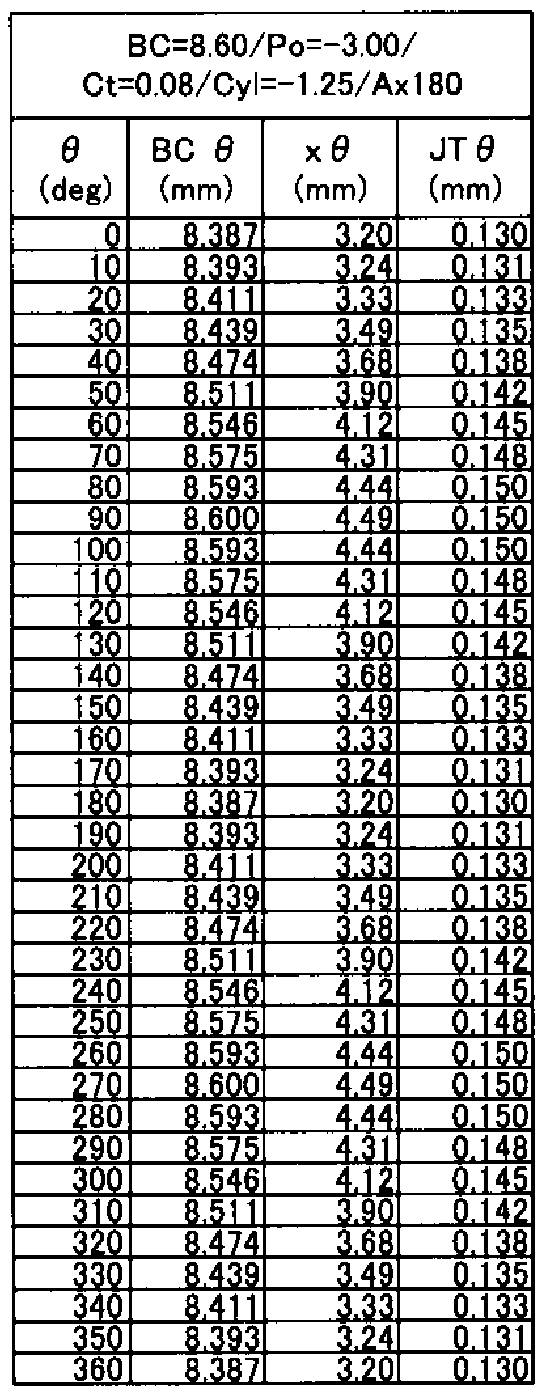
- Table 1 shows the thickness dimensions in the respective angular directions in the circumferential direction at the rear surface connecting portion 34 of each lens illustrated in FIG.
- ⁇ is a rotation angle around the lens central axis 12 with the zenith portion in the wearing state of the lens being 0 ° as shown in FIG.
- JT 0 represents the thickness dimension of the rear connection part 34 as the junction thickness in the angular direction ( ⁇ ).
- JT 0 is an axial method extending parallel to the lens center axis 12. Either the thickness dimension in the direction (LM in FIG. 2) or the thickness dimension in the radial direction (LN in FIG. 2) may be used, but in this embodiment, the thickness dimension in the radial direction is used.
- the thickness dimension of the rear surface connecting portion 34 is constant over the entire circumference (0 15mm).
- the thickness dimension CFT ⁇ ) in a predetermined angular direction ( ⁇ ) is all made equal.
- the thickness dimensional force of the connecting portion 34 between the optical portion 22 and the peripheral portion 24 is constant over the entire circumference. Therefore, it is possible to set the thickness dimension of the connection part with high accuracy regardless of the optical characteristics such as the cylinder axis angle in the optical part 22, and the desired wearing feeling and circumferential stability can be achieved. It can be realized with high accuracy and stability.
- the vertical dimension can be reduced even in the contact lens 10a having a 180 ° cylindrical axis angle, which is difficult to obtain good circumferential stability because the lens upper and lower are thicker in the conventional structure. Thus, excellent circumferential stability can be obtained.
- the circumferential thickness can be made constant, Unnecessary torque is prevented from being generated, and excellent circumferential stability can be realized.
- the series-type contact lens according to this embodiment configured to include these contact lenses 10a, 10b, and 10c has the same connection portion thickness dimension in a predetermined angular direction. Therefore, the variation in the circumferential stability of the wearing feeling between the lenses can be suppressed, and the desired wearing feeling and the circumferential stability can be stably achieved throughout the series.
- the radius of curvature (BC) that serves as a reference for the rear optical unit 20 is set to an arbitrary value in consideration of the corneal shape and the like.
- the main spherical power (P) and the center thickness (CT) of the contact lens 10 are set to arbitrary values.
- the intended main spherical power (P) can be realized. Sets the curvature radius of the front optical unit 18.
- a conventionally known ray tracing method is preferably used, and the calculation by the ray tracing method is advantageous by using a commercially available optical design software package. Can be done.
- the rear optical unit 20 in the angular direction ( ⁇ ) is set so as to give the target cylindrical power and cylindrical axis angle.
- the radius of curvature of the rear optical unit 20 can be obtained by using a ray tracing method using a commercially available optical design software package in the same manner as the front optical unit 18 described above.
- the angle direction to be selected is not particularly limited, but at least 0 °, 90 °, 180 °, which is located at each intersection of the latitude and meridian on the circumference of the optical axis 22 around the lens central axis 12.
- the radii of curvature of the rear optical unit 20 and the front optical unit 18 in the selected angular direction are respectively determined, and therefore, as shown in FIG. 4, the separation distance from the lens central axis 12 in the angular direction of the optical unit 22 as shown in FIG.
- the thickness dimension of the rear surface connecting portion 34 in the selected angular direction is arbitrarily set to a target dimension.
- the thickness dimension of the rear connection portion 34 is set to a constant value over the entire circumference around the lens central axis 12.
- the thickness dimension at a predetermined distance from the lens central axis 12 is obtained.
- the radius (X ⁇ ) of the optical portion 22 having the set thickness dimension can be obtained. For example, since the radius of the optical part is usually set to 3 mm to 5 mm, in Fig.
- the junction thickness is about 0.11 to 0. Set within 17mm
- the radius (x 0) of the optical unit 22 is obtained for all of the selected angular directions (0).
- the radius (X ⁇ ) of the optical unit 22 between the selected angular directions can be advantageously obtained by using a conventionally known interpolation method such as Lagrange interpolation or spline interpolation. In this way, the radius (X 0) of the optical part 22 that satisfies the desired thickness dimension of the rear connection part 34 can be obtained over the entire circumference.
- peripheral portion 24 is provided with a shape that is smoothly connected to the optical portion 22, and the front peripheral portion 28 and the rear peripheral portion 30 are the front optical portion 18 and the rear optical portion 20 respectively. It is set appropriately with a function or an arbitrary curve that is connected smoothly.
- the target contact lens 10 can be obtained as described above.
- contact lenses are provided as a series, for example, a plurality of contact lenses having the same spherical power and cylindrical power and different cylinder axis angles are prepared. A series is composed.
- the thickness dimension of the rear connection part 34 connecting the optical part 22 and the peripheral part 24 can be set to a desired dimension with high accuracy. Therefore, for example, as described above, it is possible to make the thickness dimension of the rear connection part 34 constant over the entire circumference. Also in this contact lens, it is possible to make the upper and lower thickness dimensions equal to other parts. Conventionally, even in a contact lens with a cylinder axis angle of 45 °, the circumferential distribution of the thickness of the connecting portion is different, the thickness of the connecting portion can be made constant in the circumferential direction. Thus, according to this manufacturing method, the target thickness dimension can be obtained with high accuracy regardless of the cylinder axis angle, and excellent wear feeling and circumferential stability can be obtained.
- the thickness dimension of the rear connection portion 34 should be set with high accuracy. Therefore, the circumferential distribution of the thickness of the rear connection portion 34 can be made equal even at any cylinder axis angle. As a result, it is possible to suppress variations in circumferential stability due to differences in the cylinder axis angle within the same series, and to achieve the desired wearing feeling and circumferential direction through all contact lenses that make up the series. Stability can be realized with high accuracy and stability.
- a predetermined angle direction in the rear connection portion 34 (for example, four cylinders of the manufacturing method, 0, 90, 180, 270). )) [Koo! After finding the diameter dimension of the rear optical part 20 that achieves the target thickness dimension, other angular direction diameter dimensions were obtained by interpolation. For example, By using a computer or the like to obtain a large number of angular dimensions in the circumferential direction of the rear connection part 34 at small intervals such as 1 ° and 0.5 °, the rear optical part 34 over the entire circumference is obtained. The diameter may be obtained.
- the target thickness dimension is set at a plurality of points separated by an appropriate circumferential distance in the rear connection part 34.
- the thickness dimension between the circumferential directions of the plurality of points may be set using a conventionally known interpolation method such as Lagrange interpolation or spline interpolation. In this way, the thickness change in the circumferential direction of the rear connection portion 34 can be made smoother.
- the forces constituting the series-type contact lens according to the second embodiment of the present invention are a plurality of appropriately selected contact lenses 40a. , 40b, 40c.
- These contact lenses 40a, 40b, and 40c are similar to the first embodiment in that optical characteristics (for example, cylindrical axis angles) are set in the optical unit and are combined with each other. It constitutes a contact lens.
- optical characteristics for example, cylindrical axis angles
- FIG. 6 the same reference numerals as those of the first embodiment are given to the members having the same structure as that of the first embodiment, and the detailed description thereof is given. Omitted.
- the series-type contact lens 40 in the present embodiment (hereinafter, in the case where the symbols: a, b, and c are not attached, all of a, b, and c are collectively referred to)
- the series-type contact lens according to the present embodiment is obtained by setting the cylinder axis angle (Ax) in the optical unit 22 in a plurality of stages.
- Table 2 shows the thickness dimensions in the respective angular directions in the circumferential direction of the rear surface connecting portions 34 of the contact lenses 40a, 40b, 40c in the present embodiment.
- the thickness dimension of the rear connection portion 34 is set in the circumferential direction.
- the angle direction is changed in ⁇ cycles that smoothly connect the angle directions of 0 °, 90 °, 180 °, and 270 °.
- the specific shape of the peripheral portion 24 is not particularly limited, but particularly in the present embodiment, the peripheral portion 24 has upper and lower portions in the wearing state, that is, an angular direction of 0 ° and The 180 ° part is formed with the thinnest wall, and the left and right parts, that is, the parts with angle directions of 90 ° and 270 ° are formed with the thickest part.
- the contact lens 40 in the present embodiment is a contact lens in which a so-called double slab-off shape is formed in the peripheral portion 24.
- the upper and lower parts of the optical unit 22 are the thinnest and the right and left parts regardless of the set value of the cylinder axis angle. Is the thickest.
- the thickness dimension of the rear optical unit 34 is made equal between the lenses in the circumferential direction around the lens central axis 12.
- the planar shape of the optical unit 22 changes depending on the thickness dimension setting in the rear surface connecting portion 34, and is not necessarily similar between the lenses. I don't mean. That is, for example, in each of the lenses 10a, 10b, and 10c in the first embodiment described above, the optical part 22 has a substantially elliptic shape, and the inclination of the major axis of the powerful ellipse is 180 °, 90 °, 45 °, respectively. However, in each of the lenses 40a, 40b, and 40c in the present embodiment, for example, in the contact lenses 40a and 40c, the planar shape of the optical unit 22 is substantially elliptical.
- the force of the ellipse with the major axis tilted to 180 ° and 45 ° is the shape of the contact lens 40b.
- the thickness dimension force of the rear surface connecting portion 34 is the thinnest angle direction at 0 ° and 180 °. Thickest at 90 ° and 270 °.
- the optical part 22 can be smoothly connected to the peripheral part 24 whose upper and lower sides are thinned and the left and right sides are thickened, and an excellent wearing feeling can be obtained.
- the left and right parts of the optical part 22 are made thick regardless of the set value of the cylinder axis angle, the gravitational action exerted on the left and right parts of the peripheral part 24 formed thick, and the optical part 22 Greater circumferential stability can also be achieved by the cooperation of the gravitational action exerted on the left and right parts.
- the contact lens 40 in the present embodiment can be particularly suitably employed for a contact lens having a double slab-off shape.
- the contact lens 40 in the present embodiment is more suitably used in a contact lens having a cylindrical axis angle of 180 ° that has conventionally been formed with a thick top and bottom and a thin left and right.
- the thickness dimension of the rear surface connecting portion 34 is aligned in the circumferential direction between the lenses constituting the series. It is possible to suppress the variation in the circumferential stability due to the difference in the optical characteristics of each other and to obtain the desired wearing feeling and the circumferential stability with high accuracy and stability regardless of the difference in the optical characteristics. It becomes possible.
- the series-type contact lens in the present embodiment can be manufactured by a method substantially similar to the manufacturing method of the series-type contact lens in the first embodiment described above.
- the diameter dimension (X ⁇ ) of the rear optical unit 20 in these four directions is obtained, and the rest
- the diameter dimension over the entire circumference of the optical unit 22 can be obtained by obtaining the diameter dimension in the angle direction using an appropriate interpolation method.
- the thickness dimension of the rear connection portion 34 is set to be the thinnest in the angular direction 0 ° that is the upper intersection with the meridian on the circumference of the optical portion 22, and the meridian It is also possible to set the thickest at 180 ° in the angular direction that is the lower intersection of and to change it at a 2 ⁇ cycle that smoothly connects these two locations.
- the upper part of the optical part 22 can be formed thin and the lower part can be formed thick.
- Such an optical part 22 can be suitably used for a contact lens having a prism ballast structure in which a prism is formed below the peripheral part 24.
- the lower part of the optical part 22 is formed thick, so that the peripheral part 24 and the lower part of the optical part 22 cooperate to produce a nost effect more effectively.
- this manufacturing method it is possible to form such a shape with high precision, and particularly with respect to a contact lens having a cylindrical axis angle of 90 °, which has conventionally been thinned at the top and bottom, with high precision. Therefore, it is possible to form a thick lower part.
- the cylinder power is set as follows. It is also possible to configure the series by making it different. For example, in addition to the lens series in the first embodiment shown in Table 1, in addition to the lenses shown in Table 3 and Table 4, including the lenses shown in Table 1, Table 3, and Table 4, One series may be configured. Here, the lens series shown in Table 3 and Table 4 are different in the cylindrical power of the contact lens 10 in the first embodiment shown in Table 1.
- the cylindrical series Degree (Cly) — 2.50D
- the degree of cylinder (Cly) —3.75D.
- the thickness dimension (JT 0) at the rear connection portion 34 is set to the entire circumference as in the contact lens 10 in the first embodiment. Throughout Table 1, Table 3, and Table 4, all are the same 0.150 mm. As a result, all of the contact lenses shown in Table 1, Table 3, and Table 4 are in the rear connection portion 34.
- the thickness dimension of the rear optical unit 34 is made equal between lenses having a constant thickness dimension over the entire circumference and having different cylindrical power and cylindrical axis angle.
- a series-type contact lens can be configured with lenses in which not only the cylinder axis angle but also the cylinder power is set in a plurality of stages.
- the thickness dimension of the rear connection portion 34 can be set with high accuracy and can be made equal for all lenses. It is possible to obtain the desired wearing feeling and circumferential stability at any cylindrical power while suppressing variations in circumferential stability caused by the difference in cylindrical power. However, if the difference in cylindrical power becomes too large, it becomes difficult to set the thickness dimension of the rear connection part 34 to a constant value. Therefore, it is preferable to set the difference width of the cylindrical power suitable for manufacturing with the thickness dimension of the rear connection portion 34 within the range of 3D, more preferably 2.5D. Set within the range.
- the curvature of the front surface of the optical unit is changed, and the thickness dimension of the optical unit is changed.
- the spherical power increases toward the negative diopter, in general, if the same junction thickness is set, the position of the connecting portion becomes the inside and the diameter of the optical portion decreases. Therefore, if the spherical power is different, it is necessary to recalculate the radius dimension of the optical part that satisfies the target thickness dimension at the spherical power.
- the radial dimension of the optical part depends on the change in the spherical power.
- the rate of change of the radial dimension of the optical part in a predetermined angular direction can be obtained without recalculating the radial dimension of the optical part according to the above manufacturing method.
- the radius dimension of the optical part in other angular directions may be obtained based on the rate of change that is applied.
- the position of the connecting portion that gives the target thickness dimension in the rear connecting portion of the rear surface of the lens is obtained as the radial dimension of the rear optical portion. It is also possible to determine the position of the connecting part as the radial dimension of the front optical part. That is, by forming a toric surface that gives the desired cylindrical power and cylindrical axis angle to the front optical part, and setting the radius of curvature that gives the desired spherical power to the rear optical part, the toric surface is given to the front optical part. It may be possible to obtain an optical part shape in which is formed. The shape of the optical part can be calculated using a ray tracing method or the like, as in the above embodiment.
- the radial dimension of the front optical part that gives the desired thickness dimension of the front connection part based on the change in the thickness of the optical part in the same manner as in the above embodiment. Can be obtained. Furthermore, the present invention can be used for both the front optical part and the rear optical part, and the radial dimension of the front optical part and the radial dimension of the rear optical part may be determined respectively.
- the present invention can also be applied to a contact lens having a bifocal spherical power that gives two focal points to the optical unit or a multi-focal spherical power that gives more focal points. It is possible to set the thickness dimension at the connecting part between the optical part given the spherical power and the peripheral part with high accuracy.
- front optical parts and rear opticals that give bifocal spherical powers and multifocal spherical powers according to a conventionally known appropriate method such as a ray tracing method.
- the radius dimension of the optical part that gives the thickness dimension of the target connection part can be obtained in the same manner as in the above embodiment. I can do it.
- the junction thickness of the connection portion is aligned to the same thickness dimension over the entire circumference of the connection portion through each contact lens constituting the series. Force It is not always necessary to have all the junction thicknesses in all angular directions all around the circumference.For example, junction thicknesses in appropriate multiple angular directions such as 0 °, 90 °, 180 °, 270 °, etc. It is also possible to have a slight error in the junction thickness in the angular direction between them.
Description


Claims
Priority Applications (4)
| Application Number | Priority Date | Filing Date | Title |
|---|---|---|---|
| EP06832970.5A EP2085809B1 (en) | 2006-11-20 | 2006-11-20 | Contact lens and method for manufacturing the same |
| JP2008545262A JP4580446B2 (ja) | 2006-11-20 | 2006-11-20 | コンタクトレンズの製造方法 |
| PCT/JP2006/323120 WO2008062503A1 (fr) | 2006-11-20 | 2006-11-20 | Lentille de contact et son procédé de fabrication |
| US12/312,281 US8038294B2 (en) | 2006-11-20 | 2006-11-20 | Contact lens and method of manufacturing the same |
Applications Claiming Priority (1)
| Application Number | Priority Date | Filing Date | Title |
|---|---|---|---|
| PCT/JP2006/323120 WO2008062503A1 (fr) | 2006-11-20 | 2006-11-20 | Lentille de contact et son procédé de fabrication |
Publications (1)
| Publication Number | Publication Date |
|---|---|
| WO2008062503A1 true WO2008062503A1 (fr) | 2008-05-29 |
Family
ID=39429444
Family Applications (1)
| Application Number | Title | Priority Date | Filing Date |
|---|---|---|---|
| PCT/JP2006/323120 WO2008062503A1 (fr) | 2006-11-20 | 2006-11-20 | Lentille de contact et son procédé de fabrication |
Country Status (4)
| Country | Link |
|---|---|
| US (1) | US8038294B2 (ja) |
| EP (1) | EP2085809B1 (ja) |
| JP (1) | JP4580446B2 (ja) |
| WO (1) | WO2008062503A1 (ja) |
Cited By (5)
| Publication number | Priority date | Publication date | Assignee | Title |
|---|---|---|---|---|
| WO2011129060A1 (ja) * | 2010-04-14 | 2011-10-20 | 株式会社メニコン | 不正乱視矯正用コンタクトレンズ |
| JP2013218355A (ja) * | 2013-07-30 | 2013-10-24 | Menicon Co Ltd | コンタクトレンズ |
| JP5335099B2 (ja) * | 2009-11-17 | 2013-11-06 | 株式会社メニコン | コンタクトレンズ |
| JP5536289B1 (ja) * | 2012-07-18 | 2014-07-02 | 株式会社メニコン | コンタクトレンズおよびコンタクトレンズの製造方法 |
| JP2021092820A (ja) * | 2015-06-12 | 2021-06-17 | ジョンソン・アンド・ジョンソン・ビジョン・ケア・インコーポレイテッドJohnson & Johnson Vision Care, Inc. | 非回転対称の眼の収差のための快適性が最適化されたコンタクトレンズシステム |
Families Citing this family (20)
| Publication number | Priority date | Publication date | Assignee | Title |
|---|---|---|---|---|
| KR101683042B1 (ko) * | 2008-04-04 | 2016-12-06 | 포사이트 비젼4, 인크. | 통증 관리 및 시력을 위한 치료 장치 |
| WO2011050327A1 (en) | 2009-10-23 | 2011-04-28 | Forsight Labs Llc | Corneal denervation for treatment of ocular pain |
| US9498385B2 (en) | 2009-10-23 | 2016-11-22 | Nexisvision, Inc. | Conformable therapeutic shield for vision and pain |
| US8591025B1 (en) | 2012-09-11 | 2013-11-26 | Nexisvision, Inc. | Eye covering and refractive correction methods for LASIK and other applications |
| AU2011323743B2 (en) | 2010-10-25 | 2016-01-28 | Nexisvision, Inc. | Methods and apparatus to identify eye coverings for vision |
| US8801175B2 (en) * | 2011-02-23 | 2014-08-12 | Crt Technology, Inc. | System and method for communicating the geometry of a contact lens |
| US8678584B2 (en) | 2012-04-20 | 2014-03-25 | Nexisvision, Inc. | Contact lenses for refractive correction |
| AU2012249773A1 (en) | 2011-04-28 | 2013-11-07 | Nexisvision, Inc. | Eye covering and refractive correction methods and apparatus having improved tear flow, comfort, and/or applicability |
| JP6298810B2 (ja) | 2012-04-20 | 2018-03-20 | ネクシスビジョン リクイデーション トラスト | 屈折矯正のためのコンタクトレンズ |
| US9465233B2 (en) | 2012-04-20 | 2016-10-11 | Nexisvision, Inc. | Bimodular contact lenses |
| CA2916885A1 (en) | 2013-06-26 | 2014-12-31 | Nexisvision, Inc. | Contact lenses for refractive correction |
| US9341864B2 (en) | 2013-11-15 | 2016-05-17 | Nexisvision, Inc. | Contact lenses having a reinforcing scaffold |
| WO2015116559A1 (en) | 2014-01-29 | 2015-08-06 | Nexisvision, Inc. | Multifocal bimodulus contact lenses |
| DE102014113968A1 (de) * | 2014-09-26 | 2016-03-31 | Carl Zeiss Meditec Ag | Augenlinse mit ringförmigen optischen Zonen, die individuelle torisch brechende Oberflächenprofile aufweisen |
| KR101556997B1 (ko) * | 2015-03-09 | 2015-10-06 | 주식회사 비에스코퍼레이션 | 토릭렌즈용 몰드 |
| KR101556995B1 (ko) * | 2015-03-09 | 2015-10-06 | 주식회사 비에스코퍼레이션 | 토릭렌즈 제조방법 |
| US10845622B2 (en) | 2015-09-15 | 2020-11-24 | Largan Medical Co., Ltd. | Multifocal contact lens and contact lens product |
| US10274751B2 (en) * | 2016-07-05 | 2019-04-30 | Bausch & Lomb Incorporated | Prism ballasted contact lens |
| TWI639028B (zh) * | 2016-09-02 | 2018-10-21 | 星歐光學股份有限公司 | 隱形眼鏡產品 |
| CN113031306B (zh) * | 2020-07-22 | 2023-06-13 | 上海艾康特医疗科技有限公司 | 巩膜接触镜的配镜方法 |
Citations (6)
| Publication number | Priority date | Publication date | Assignee | Title |
|---|---|---|---|---|
| US5125728A (en) | 1988-02-03 | 1992-06-30 | Igel International Limited | Soft contact lens for the correction of astigmatism |
| JP2695056B2 (ja) | 1990-01-29 | 1997-12-24 | ウェズリー−ジェッセン・コーポレーション | 乱視矯正用コンタクトレンズ |
| JP2001519046A (ja) | 1997-04-07 | 2001-10-16 | ボシュ アンド ロム インコーポレイテッド | トーリックコンタクトレンズ |
| WO2002048779A2 (en) | 2000-11-15 | 2002-06-20 | Johnson & Johnson Vision Care, Inc. | Method for designing contact lenses |
| JP2003228028A (ja) * | 2001-11-30 | 2003-08-15 | Menicon Co Ltd | コンタクトレンズおよびコンタクトレンズの設計方法 |
| EP1496388A1 (en) | 2002-04-12 | 2005-01-12 | Menicon Co., Ltd. | Contact lens and production method for contact lens |
Family Cites Families (9)
| Publication number | Priority date | Publication date | Assignee | Title |
|---|---|---|---|---|
| US3781096A (en) * | 1972-11-01 | 1973-12-25 | Jessen Inc Wesley | Method and apparatus for designing contact lenses |
| US5191365B1 (en) * | 1991-08-23 | 2000-08-15 | Contex Inc | Corneal contact lens and method for treating myopia |
| US5428412B1 (en) * | 1991-08-23 | 2000-08-08 | Contex Inc | Method for treating myopia with an aspheric corneal contact lens |
| US5349395A (en) * | 1991-08-23 | 1994-09-20 | Nick Stoyan | Multiple focus corneal contact lens and method for treating myopia |
| US6467903B1 (en) * | 2000-03-31 | 2002-10-22 | Ocular Sciences, Inc. | Contact lens having a uniform horizontal thickness profile |
| AU2003260369A1 (en) * | 2002-08-06 | 2004-02-25 | Novartis Ag | Contact lenses |
| JPWO2005040896A1 (ja) * | 2003-10-27 | 2007-03-29 | 株式会社メニコン | コンタクトレンズ |
| JP2005148147A (ja) * | 2003-11-11 | 2005-06-09 | Menicon Co Ltd | トーリックコンタクトレンズのモールド成形装置 |
| JP2005202107A (ja) * | 2004-01-15 | 2005-07-28 | Asahi Kasei Aimii Kk | 2焦点コンタクトレンズ |
-
2006
- 2006-11-20 JP JP2008545262A patent/JP4580446B2/ja active Active
- 2006-11-20 EP EP06832970.5A patent/EP2085809B1/en active Active
- 2006-11-20 US US12/312,281 patent/US8038294B2/en not_active Expired - Fee Related
- 2006-11-20 WO PCT/JP2006/323120 patent/WO2008062503A1/ja active Application Filing
Patent Citations (6)
| Publication number | Priority date | Publication date | Assignee | Title |
|---|---|---|---|---|
| US5125728A (en) | 1988-02-03 | 1992-06-30 | Igel International Limited | Soft contact lens for the correction of astigmatism |
| JP2695056B2 (ja) | 1990-01-29 | 1997-12-24 | ウェズリー−ジェッセン・コーポレーション | 乱視矯正用コンタクトレンズ |
| JP2001519046A (ja) | 1997-04-07 | 2001-10-16 | ボシュ アンド ロム インコーポレイテッド | トーリックコンタクトレンズ |
| WO2002048779A2 (en) | 2000-11-15 | 2002-06-20 | Johnson & Johnson Vision Care, Inc. | Method for designing contact lenses |
| JP2003228028A (ja) * | 2001-11-30 | 2003-08-15 | Menicon Co Ltd | コンタクトレンズおよびコンタクトレンズの設計方法 |
| EP1496388A1 (en) | 2002-04-12 | 2005-01-12 | Menicon Co., Ltd. | Contact lens and production method for contact lens |
Cited By (7)
| Publication number | Priority date | Publication date | Assignee | Title |
|---|---|---|---|---|
| JP5335099B2 (ja) * | 2009-11-17 | 2013-11-06 | 株式会社メニコン | コンタクトレンズ |
| WO2011129060A1 (ja) * | 2010-04-14 | 2011-10-20 | 株式会社メニコン | 不正乱視矯正用コンタクトレンズ |
| JP2011221446A (ja) * | 2010-04-14 | 2011-11-04 | Menicon Co Ltd | 不正乱視矯正用コンタクトレンズ |
| US8789945B2 (en) | 2010-04-14 | 2014-07-29 | Menicon Co., Ltd. | Contact lens for correction of irregular astigmatism |
| JP5536289B1 (ja) * | 2012-07-18 | 2014-07-02 | 株式会社メニコン | コンタクトレンズおよびコンタクトレンズの製造方法 |
| JP2013218355A (ja) * | 2013-07-30 | 2013-10-24 | Menicon Co Ltd | コンタクトレンズ |
| JP2021092820A (ja) * | 2015-06-12 | 2021-06-17 | ジョンソン・アンド・ジョンソン・ビジョン・ケア・インコーポレイテッドJohnson & Johnson Vision Care, Inc. | 非回転対称の眼の収差のための快適性が最適化されたコンタクトレンズシステム |
Also Published As
| Publication number | Publication date |
|---|---|
| JPWO2008062503A1 (ja) | 2010-03-04 |
| US20100060849A1 (en) | 2010-03-11 |
| EP2085809B1 (en) | 2017-07-12 |
| EP2085809A1 (en) | 2009-08-05 |
| US8038294B2 (en) | 2011-10-18 |
| JP4580446B2 (ja) | 2010-11-10 |
| EP2085809A4 (en) | 2010-12-22 |
Similar Documents
| Publication | Publication Date | Title |
|---|---|---|
| WO2008062503A1 (fr) | Lentille de contact et son procédé de fabrication | |
| EP2955566B1 (en) | Toric lens | |
| JP4442927B2 (ja) | 傾斜装用型コンタクトレンズ | |
| JP5335099B2 (ja) | コンタクトレンズ | |
| JP5097122B2 (ja) | 円環面コンタクトレンズ | |
| JP5946981B2 (ja) | ディセンタタイプのコンタクトレンズおよびディセンタタイプのコンタクトレンズセット | |
| JP2007503011A5 (ja) | ||
| JP5448789B2 (ja) | トーリックコンタクトレンズ及びその製造方法 | |
| KR102553989B1 (ko) | 콘택트 렌즈 및 그 제조 방법 | |
| KR20100040958A (ko) | 개선된 후방 표면 설계를 갖는 원환체 콘택트 렌즈 | |
| WO2005040896A1 (ja) | コンタクトレンズ | |
| JP4942762B2 (ja) | トーリック・コンタクトレンズ | |
| JP4009185B2 (ja) | コンタクトレンズの製作方法 | |
| US9778487B2 (en) | Rotationally stabilized contact lens with improved comfort and method of optimization | |
| US6357876B1 (en) | Multifocal ocular lens having intermediate-distance vision correction region formed in central part of vision correction area | |
| JP5536289B1 (ja) | コンタクトレンズおよびコンタクトレンズの製造方法 | |
| JP4298515B2 (ja) | 偏心球体面を有するコンタクトレンズ | |
| TW202321780A (zh) | 眼用鏡片 | |
| CN115867229A (zh) | 眼科透镜 | |
| JP5536265B2 (ja) | コンタクトレンズ | |
| JP2004294456A (ja) | 多焦点型眼用レンズ | |
| JP2023550996A (ja) | レンズ要素 | |
| TW202332966A (zh) | 隱形眼鏡及其相關方法 |
Legal Events
| Date | Code | Title | Description |
|---|---|---|---|
| 121 | Ep: the epo has been informed by wipo that ep was designated in this application |
Ref document number: 06832970 Country of ref document: EP Kind code of ref document: A1 |
|
| WWE | Wipo information: entry into national phase |
Ref document number: 2008545262 Country of ref document: JP |
|
| WWE | Wipo information: entry into national phase |
Ref document number: 12312281 Country of ref document: US |
|
| REEP | Request for entry into the european phase |
Ref document number: 2006832970 Country of ref document: EP |
|
| WWE | Wipo information: entry into national phase |
Ref document number: 2006832970 Country of ref document: EP |
|
| NENP | Non-entry into the national phase |
Ref country code: DE |