WO2006095678A1 - 配線接続器具用金属材 - Google Patents
配線接続器具用金属材 Download PDFInfo
- Publication number
- WO2006095678A1 WO2006095678A1 PCT/JP2006/304257 JP2006304257W WO2006095678A1 WO 2006095678 A1 WO2006095678 A1 WO 2006095678A1 JP 2006304257 W JP2006304257 W JP 2006304257W WO 2006095678 A1 WO2006095678 A1 WO 2006095678A1
- Authority
- WO
- WIPO (PCT)
- Prior art keywords
- metal material
- copper
- wiring connection
- roughness
- metal
- Prior art date
- Legal status (The legal status is an assumption and is not a legal conclusion. Google has not performed a legal analysis and makes no representation as to the accuracy of the status listed.)
- Ceased
Links
Classifications
-
- C—CHEMISTRY; METALLURGY
- C22—METALLURGY; FERROUS OR NON-FERROUS ALLOYS; TREATMENT OF ALLOYS OR NON-FERROUS METALS
- C22C—ALLOYS
- C22C9/00—Alloys based on copper
- C22C9/02—Alloys based on copper with tin as the next major constituent
-
- C—CHEMISTRY; METALLURGY
- C22—METALLURGY; FERROUS OR NON-FERROUS ALLOYS; TREATMENT OF ALLOYS OR NON-FERROUS METALS
- C22C—ALLOYS
- C22C21/00—Alloys based on aluminium
- C22C21/06—Alloys based on aluminium with magnesium as the next major constituent
- C22C21/08—Alloys based on aluminium with magnesium as the next major constituent with silicon
-
- C—CHEMISTRY; METALLURGY
- C22—METALLURGY; FERROUS OR NON-FERROUS ALLOYS; TREATMENT OF ALLOYS OR NON-FERROUS METALS
- C22C—ALLOYS
- C22C38/00—Ferrous alloys, e.g. steel alloys
- C22C38/08—Ferrous alloys, e.g. steel alloys containing nickel
-
- C—CHEMISTRY; METALLURGY
- C22—METALLURGY; FERROUS OR NON-FERROUS ALLOYS; TREATMENT OF ALLOYS OR NON-FERROUS METALS
- C22C—ALLOYS
- C22C38/00—Ferrous alloys, e.g. steel alloys
- C22C38/18—Ferrous alloys, e.g. steel alloys containing chromium
- C22C38/40—Ferrous alloys, e.g. steel alloys containing chromium with nickel
-
- C—CHEMISTRY; METALLURGY
- C22—METALLURGY; FERROUS OR NON-FERROUS ALLOYS; TREATMENT OF ALLOYS OR NON-FERROUS METALS
- C22C—ALLOYS
- C22C9/00—Alloys based on copper
-
- C—CHEMISTRY; METALLURGY
- C22—METALLURGY; FERROUS OR NON-FERROUS ALLOYS; TREATMENT OF ALLOYS OR NON-FERROUS METALS
- C22C—ALLOYS
- C22C9/00—Alloys based on copper
- C22C9/04—Alloys based on copper with zinc as the next major constituent
-
- C—CHEMISTRY; METALLURGY
- C22—METALLURGY; FERROUS OR NON-FERROUS ALLOYS; TREATMENT OF ALLOYS OR NON-FERROUS METALS
- C22C—ALLOYS
- C22C9/00—Alloys based on copper
- C22C9/06—Alloys based on copper with nickel or cobalt as the next major constituent
-
- H—ELECTRICITY
- H01—ELECTRIC ELEMENTS
- H01R—ELECTRICALLY-CONDUCTIVE CONNECTIONS; STRUCTURAL ASSOCIATIONS OF A PLURALITY OF MUTUALLY-INSULATED ELECTRICAL CONNECTING ELEMENTS; COUPLING DEVICES; CURRENT COLLECTORS
- H01R13/00—Details of coupling devices of the kinds covered by groups H01R12/70 or H01R24/00 - H01R33/00
- H01R13/02—Contact members
- H01R13/03—Contact members characterised by the material, e.g. plating, or coating materials
Definitions
- the present invention relates to a metal material for a wiring connection device in which at least one of the metal members of the wiring connection device is copper or a copper alloy material, and in particular, can prevent generation of gloss and proliferation of cuprous oxide.
- the present invention relates to a metal material for a wiring connector.
- Wiring connection devices are widely used in electrical connection parts such as electrical appliance outlets and lighting switches.
- a metal is generally used for the connecting portion, and electrical connection is made by contact between the metals.
- heat generation has been a problem at the contact portion. It has been discovered that a minute discharge (glow) occurs at the contact area, which leads to the growth of cuprous oxide, which increases contact resistance and generates heat! Speak.
- the present inventors have conducted a detailed study on the contact portion of the wiring connection device, found that there is a relationship between the roughness (roughness) of the material surface and the occurrence of gloss, and based on this knowledge, have further studied. Over time, the present invention has been completed.
- At least one of the metal members in the wiring connection between the metal members is a metal material for a wiring connecting device, which is copper or a copper alloy material, and the average roughness Ra of the surface of at least one connection portion of the metal members is 0.
- a metal material for a wiring connector characterized by having a maximum roughness Rt of 2. O / zm or less and having excellent anti-glow properties, and
- the ratio of average roughness Ra to maximum roughness Rt RtZRa is 10 or less.
- the metal material for a wiring connector according to the present invention limits the average roughness Ra and the maximum roughness Rt, and preferably further adjusts the ratio of the average roughness Ra to the maximum roughness Rt to thereby improve the gloss. It is a metal material suitable for wiring connection equipment such as electrical appliance outlets and lighting switches, which can prevent the generation of copper and the growth of cuprous oxide and suppress heat generation.
- FIG. 1 is a schematic diagram of a measuring apparatus for glow resistance and cuprous oxide growth characteristics used in Examples.
- the definition of roughness follows IS B 0601: 2001. That is, in the present invention, the average roughness Ra refers to the arithmetic average roughness of the preceding 6JIS B 0601: 2001. Similarly, in the present invention, the maximum roughness Rt is the roughness curve of the preceding 6JIS B 0601: 2001. This refers to the maximum section height.
- At least one of the metal members in the wiring connection between the metal members is copper / steel is a copper alloy material.
- the average roughness Ra of the surface of at least one connection part (contact point) of the metal member is 0.3 ⁇ m or less and the maximum roughness Rt is 2 ⁇ m or less, and any metal member It is preferable that the average roughness Ra is 0.3 ⁇ m or less and the maximum roughness Rt is 2 ⁇ m or less. In the present invention, the average roughness Ra is 0.3 ⁇ m or less and the maximum roughness Rt is 2 ⁇ m or less.
- the metal member force is copper or a copper alloy material, and it is not a copper or copper alloy material. In the case of a metal material (for example, Ni alloy material).
- Roughness is one of the guidelines for showing the unevenness of the material surface, but it is thought that the voltage applied to the tip of the unevenness is concentrated and causes a glow discharge.
- the average roughness Ra exceeds 0.3 ⁇ m, glow discharge is likely to occur. End up.
- it is 0.2 / zm or less.
- the maximum roughness Rt exceeds 2 m, glow discharge is likely to occur.
- the maximum roughness Rt exceeds 2 m, glow discharge is likely to occur.
- it is 1 ⁇ m or less.
- the average roughness Ra and the maximum roughness Rt are preferably as small as possible.
- the lower limit of average roughness Ra and maximum roughness Rt is not particularly limited, but average roughness Ra is usually preferably 0.01 ⁇ m or more, and maximum roughness Rt is usually 0.05 ⁇ m or more. It is preferable.
- the ratio RtZRa between the maximum roughness Rt and the average roughness Ra is preferably 10 or less.
- the ratio of maximum roughness Rt to average roughness Ra When RtZRa is 10 or less, the generation of gloss can be further reduced. If RtZRa is too large, a portion with locally large irregularities exists, and it is considered that a glow discharge is likely to occur at that portion.
- RtZRa is preferably 5 or less.
- the RtZRa is preferably as small as possible.
- the lower limit value of the ratio RtZRa is not particularly limited, but the ratio RtZRa is usually preferably 2 or more.
- the metal material for a wiring connector according to the present invention requires contact pressure and electrical conductivity at a contact point
- a metal having excellent strength and conductivity is generally used.
- stainless steel, Ni alloy, and copper alloy are preferable because of their excellent strength and conductivity. More preferably, the tensile strength is 500 MPa or more, and the conductivity is 30% IACS or more.
- Ni 1.0 to 5. Omass%, Si: 0.3 to 1.3 mass%, at least one element of Mg, Sn, and Zn in total.
- a copper alloy consisting of copper and inevitable impurities, or
- the metal material for a wiring connector according to the present invention is manufactured by appropriately repeating forging, hot rolling, cold rolling, heat treatment and the like by a general manufacturing method.
- a method for controlling the average roughness Ra and the maximum roughness Rt the surface is washed with an acid or alkali or the like, and the roll roughness in the cold rolling process is changed.
- a plate material having a thickness of 0.15 to 0.25 mm made of a commercially available copper alloy and non-ferrous material was obtained, and the tensile strength, hardness, and conductivity were investigated.
- Tensile strength IS-5 test piece was cut out from the parallel direction of rolling and measured according to JIS Z 2241. Hardness was measured from the surface of the material according to JIS Z 2244 mm with a load of lOOg.
- the electrical conductivity was measured at a distance of 100 mm between terminals in accordance with JIS H 3200 by cutting a test piece having a width of 10 mm and a length of 150 mm from the rolling parallel direction. The results are shown in Tables 1 and 2. Note that the strength, hardness, and conductivity differ even with the same alloy composition because the tempering and manufacturing conditions are different.
- the surface of the plate material is polished with various counts of emery paper (abrasive paper with SiC abrasive grains attached to the surface) in the same direction as the rolling direction (direction parallel to the rolling). Made materials with different degrees.
- the plate material was fixed on a smooth surface plate, the emery paper strength of # 230 was increased in turn, polished 30 times with 8 stages of emery paper up to # 4000, and then the surface was washed. It was judged that the cuprous oxide on the surface layer was removed by the polishing, and the following evaluation was performed.
- Figure 1 shows a schematic diagram of the equipment used to measure the anti-glow properties and the cuprous oxide growth characteristics.
- the anti-glow property was evaluated as follows. That is, a copper wire 2 with a diameter of 2 mm is attached to the holder 1 with a load adder, and the sample 3 of the present invention example and the comparative example is placed on the sample holder 4 Then, it is brought into contact with the copper wire 2, and the current flowing between the copper wire 2 and the sample 3 is set to 4 A using the slidac (single transformer, trade name, manufactured by Toshiba) 8 and the variable resistor 6. Next, the sample holder 14 was vibrated with the vibrator 5, and the voltage waveform between the copper wire 2 and the sample 3 was observed with the oscilloscope 7. When a gloss (microdischarge) occurs between the copper wire 2 and the sample 3, the waveform of the oscilloscope scope 7 changes.
- the gloss resistance is increased at the frequency (number of times) added until this waveform change occurs.
- the characteristics were evaluated.
- the evaluation of the anti-glow characteristics is that the vibration applied to the waveform change that indicates the occurrence of glow is 1000 times or less, and the case where it exceeds 1000 times and 2000 times or less is acceptable, and 2000 times If it exceeds
- cuprous oxide-resistant growth characteristics were evaluated as follows. At the same time as the occurrence of the gloss was confirmed, the vibration by the vibrator 5 was stopped, and the sample 3 was left for 60 minutes. Next, Sample 3 was taken out, and cuprous oxide produced on the surface of Sample 3 was collected, and its mass was measured. This mass, that is, the cuprous oxide growth amount (mg) was used to evaluate the cuprous oxide growth resistance. In the evaluation of the growth resistance of cuprous oxide, the case where the amount of cuprous oxide generated (mg) was 200 mg or less was judged good, the case where it exceeded 200 mg and 250 mg or less was acceptable, and the case where it exceeded 250 mg was regarded as poor.
- the plate materials of the present invention shown in Nos. 1 to 84 and 601 to 604 are excellent in anti-glowing property and excellent in the amount of cuprous oxide.
- the metal material for a wiring connector according to the present invention limits the average roughness Ra and the maximum roughness Rt, and preferably further adjusts the ratio of the average roughness Ra to the maximum roughness Rt to thereby improve the gloss.
- This is suitable as a metal material used for wiring connection devices such as electrical appliance outlets and illumination switches.
Landscapes
- Chemical & Material Sciences (AREA)
- Engineering & Computer Science (AREA)
- Materials Engineering (AREA)
- Mechanical Engineering (AREA)
- Metallurgy (AREA)
- Organic Chemistry (AREA)
- Conductive Materials (AREA)
- Non-Insulated Conductors (AREA)
Abstract
金属部材同士の配線接続における前記金属部材の少なくとも一方が銅ないしは銅合金材である配線接続器具用金属材であって、前記金属部材の少なくとも一方の接続部表面の平均粗さRaが0.3μm以下、最大粗さRtが2.0μm以下である、耐グロー特性に優れる配線接続器具用金属材。
Description
明 細 書
配線接続器具用金属材
技術分野
[0001] 本発明は、配線接続器具の金属部材の少なくとも一方が銅又は銅合金材である配 線接続器具用金属材に関するものであり、特にグロ一の発生及び亜酸化銅の増殖を 防止できる配線接続器具用金属材に関するものである。
背景技術
[0002] 配線接続器具は電気器具のコンセントや照明のスィッチなど電気的な接続部に広 く用いられている。前記接続部には金属が一般的に用いられており、金属同士が接 触することで電気的な接続を行う。前記接触部では従来力 発熱が問題となって 、る 。これは接触部に微小放電 (グロ一)が発生し、これが起因となって亜酸化銅の増殖 が誘発され接触抵抗が増加し、発熱することが知見されて!ヽる。
[0003] 合金成分を見直すことでグロ一及び亜酸化銅の増殖の起きにく!、配線接続器具用 銅合金が提案されている。
[0004] しかし、合金成分を検討しても、グロ一の発生及び亜酸化銅の増殖による発熱を防 止することはできなかった。
発明の開示
[0005] 本発明者らは配線接続器具の接触部について詳細な検討を行い、材料表面の荒 さ (粗度)とグロ一発生とに関連があることを見出し、この知見に基づき更に検討を重 ねて、本発明を完成させるに至った。
本発明によれば、以下の手段が提供される:
(1)金属部材同士の配線接続における前記金属部材の少なくとも一方が銅ないしは 銅合金材である配線接続器具用金属材であって、前記金属部材の少なくとも一方の 接続部表面の平均粗さ Raが 0. 以下、最大粗さ Rtが 2. O /z m以下である、耐グ ロー特性に優れることを特徴とする配線接続器具用金属材、及び
(2)平均粗さ Raと最大粗さ Rtの比 RtZRaが 10以下であることを特徴とする耐グロー 特性に優れた (1)記載の配線接続器具用金属材。
[0006] 本発明の配線接続器具用金属材は、平均粗さ Ra及び最大粗さ Rtを限定し、好ま しくはさらに平均粗さ Raと最大粗さ Rtの比を調節することで、グロ一の発生及び亜酸 ィ匕銅の増殖を防止でき、発熱を抑制することを可能とし、電気器具のコンセントや照 明のスィッチなどの配線接続器具に適した金属材である。
本発明の上記及び他の特徴及び利点は、添付の図面とともに考慮することにより、 下記の記載力 より明らかになるであろう。
図面の簡単な説明
[0007] [図 1]図 1は、実施例で用いた耐グロー特性及び耐亜酸化銅増殖特性の測定装置の 模式図である。
発明を実施するための最良の形態
[0008] 本発明の好ましい実施の態様について、詳細に説明する。なお、本発明において 、粗さの定義 ίお IS B 0601 : 2001に従う。すなわち、本発明において平均粗さ Ra は、前言 6JIS B 0601 : 2001の算術平均粗さのことを指し、同様に、本発明におい て最大粗さ Rtは、前言 6JIS B 0601 : 2001の粗さ曲線の最大断面高さのことを指 す。
[0009] 本発明にお 、て、金属部材同士の配線接続における前記金属部材の少なくとも一 方が銅な!/ヽしは銅合金材である。
本発明にお ヽて、前記金属部材の少なくとも一方の接続部 (接点)表面の平均粗さ Raは 0. 3 μ m以下でかつ最大粗さ Rtが 2 μ m以下であり、いずれの金属部材もが平 均粗さ Raは 0. 3 μ m以下でかつ最大粗さ Rtが 2 μ m以下であることが好ましい。 本発明において、前記平均粗さ Raは 0. 3 μ m以下でかつ最大粗さ Rtが 2 μ m以 下である金属部材力 銅ないしは銅合金材である場合と、銅ないしは銅合金材では な 、金属材 (例えば、 Ni合金材)の場合とが挙げられる。
前記平均粗さ Raは 0. 3 μ m以下でかつ最大粗さ Rtが 2 μ m以下であるのは、グロ 一発生が著しく低減できるからである。
粗度とは材料表面の凹凸を示す指針の一つであるが、その凹凸の先端に印加され た電圧が集中して、グロ一放電を起こすと考えられる。
本発明において平均粗さ Raが 0. 3 μ mを超えるとグロ一放電が発生しやすくなつ
てしまう。好ましくは 0. 2 /z m以下である。
また、最大粗さ Rtが 2 mを超えると同様にグロ一放電が発生しやすくなつてしまう 。好ましくは 1 μ m以下である。
なお、平均粗さ Ra及び最大粗さ Rtは小さいほど好ましい。平均粗さ Ra及び最大粗 さ Rtの下限値には特に制限はないが、平均粗さ Raは通常 0.01 μ m以上であること が好ましぐまた最大粗さ Rtは通常 0.05 μ m以上であることが好ましい。
[0010] 本発明において、最大粗さ Rtと平均粗さ Raとの比 RtZRaが 10以下であることが 好ましい。
最大粗さ Rtと平均粗さ Raとの比 RtZRaが 10以下の場合に、グロ一発生をより低 減できる。 RtZRaが大きすぎると、局所的に凹凸が大きい部位が存在することになり 、その部位でグロ一放電が起こりやすくなると考えられる。
本発明において好ましくは RtZRaが 5以下である。なお、前記 RtZRaは小さいほ ど好ましい。比 RtZRaの下限値には特に制限はないが、比 RtZRaは通常 2以上で あることが好ましい。
[0011] 本発明の配線接続器具用金属材には接点における接触圧力と電気伝導性が求め られるため、一般的に強度と導電性に優れる金属が用いられている。その中でも、ス テンレスや Ni合金、銅合金は強度及び導電性に優れており、好ましい。より好ましく は、引張強度が 500MPa以上、導電率が 30%IACS以上である。
[0012] 前記のより好ましい例として、
(1) Snを 0. 1〜: LOmass%、 Pを 0. 001〜0. 5mass%含み、残部が銅と不可避不 純物からなる銅合金、
(2) Crを 0. 1〜1. Omass%、 Sn又は Znの少なくとも一種の元素を 0. 05〜5mass %含み、残部が銅と不可避不純物からなる銅合金、
(3) Niを 1. 0〜5. Omass%、 Siを 0. 3〜1. 3mass%、 Mg、 Sn、 Znの少なくとも一 種の元素を合計で 0. 05-5. Omass%含み、残部が銅と不可避不純物からなる銅 合金、又は
(4) Feを 0. 5〜3. Omass%、 Pを 0. 1〜1. Omass%含み、残部が銅と不可避不純 物からなる銅合金
が挙げられる。
[0013] 本発明の配線接続器具用金属材は、一般的な製造方法により、铸造、熱間圧延、 冷間圧延、熱処理等を適宜繰り返して製造される。また、平均粗さ Ra、最大粗さ Rtを 制御する方法として、酸'アルカリ等により表面を洗浄処理する方法、また冷間圧延 工程におけるロール粗度を変えることで行う。
実施例
[0014] 以下に本発明を実施例に基づいてさらに詳細に説明するが、本発明はこれらに限 定されるものではない。
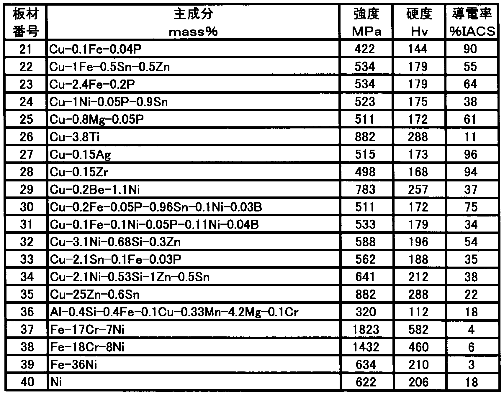
[0015] 市販されている銅合金および非鉄材料からなる板厚 0. 15〜0. 25mmの板材を入 手し、引張強度、硬度、導電率を調査した。引張強度〖お IS— 5号試験片を圧延平行 方向から切り出し、 JIS Z 2241に準じて測定した。硬度は材料表面から、 JIS Z 2244〖こ準じて荷重 lOOg重で測定した。導電率は幅 10mm X長さ 150mmの試験 片を圧延平行方向から切り出し、 JIS H 3200に準じて端子間距離 100mmで測定 した。結果を表 1、表 2に示す。なお、同一合金組成であっても強度、硬度、導電率が 異なるのは、調質や製造条件が異なるためである。
[0016] [表 1]
^

表 2
[0018] 前記板材の表面を圧延方向と同方向(圧延と平行な方向)に種々の番手のエメリー 紙 (表面に SiCの砥粒が付着した研磨紙)を用いて研磨を行 ヽ、表面粗度の異なる 材料を作成した。すなわち、板材は平滑な定盤上に固定しておき、 # 230のエメリー 紙力も順番に番手を上げて # 4000までの 8段階のエメリー紙により 30回研磨し、次 いで表面を洗浄した。前記研磨により、表層の亜酸化銅を除去したものと判断し、後 述の評価を行った。
[0019] 表面粗度の測定 «JIS H 3406に準じて測定した。触針の走査は材料の圧延方 向あるいはェメリ一紙で研磨した方向と垂直方向に 4mm行 、、その測定を 3回繰り返 して平均値を求めた。
[0020] これらの板材について、耐グロー特性及び耐亜酸化銅増殖特性を評価した。
図 1に耐グロ一特性及び耐亜酸化銅増殖特性の測定に用いた装置の模式図を示 す。
耐グロー特性は以下の様に評価した。すなわち、直径 2mmの銅線 2を荷重付加器 付ホルダー 1に取付け、本発明例及び比較例の試料 3を試料ホルダー 4の上に配置
し、銅線 2と接触させ、スライダック (単卷変圧器、商品名、東芝製) 8と可変抵抗器 6 を用いて上記銅線 2及び試料 3の間に流れる電流を 4Aにする。次いで試料ホルダ 一 4を振動器 5により振動させ、前記銅線 2と試料 3の間の電圧波形をオシロスコープ 7により観察した。前記銅線 2と試料 3の間にグロ一 (微小放電)が発生すると、オシ口 スコープ 7の波形が変化するため、この波形変化が発生するまでに付加した振動数( 回数)で耐グロ一特性を評価した。耐グロー特性の評価としては、このグロ一発生を 示す波形変化が発生するまでに付加した振動が 1000回以下の場合を不良とし、 10 00回を超え 2000回以下の場合を可とし、 2000回を超える場合を良とした。
[0021] 次に耐亜酸化銅増殖特性を以下のように評価した。前記グロ一発生が確認される と同時に振動器 5による振動を停止し、試料 3を 60分放置した。次いで、試料 3を取り 出し、前記試料 3の表面に生成した亜酸化銅を集め、質量を測定した。この質量すな わち亜酸化銅増殖量 (mg)で耐亜酸化銅増殖性を評価した。耐亜酸化銅増殖性の 評価としては、この亜酸化銅発生量 (mg)が 200mg以下の場合を良とし、 200mgを 超え 250mg以下の場合を可とし、 250mgを超える場合を不良とした。
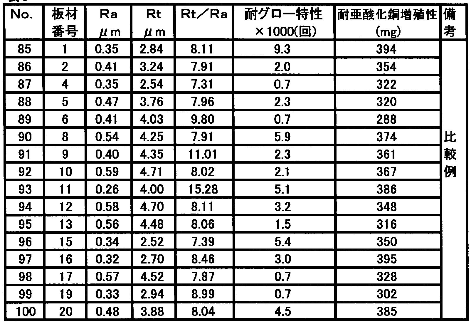
結果を表 3乃至 7に示す。
[0022] [表 3]
表 3


表 6
No. 板材 Ra Rt RtZRa 耐グロー特性 耐亜酸化銅増殖性備 番号 U m fl m X 1000(回) (mg) 考
101 21 0.39 3.20 8.22 3.3 327
102 22 0.21 3.35 15.75 1 .2 332
103 23 0.22 3.36 15.23 1.0 31 1
104 24 0.44 2.54 5.72 3.4 328
105 25 0.23 3.45 15.05 8.2 366
106 26 0.13 2.41 18.28 2.0 305
107 27 0.49 3.86 7.93 6.1 375 比
108 28 0.23 2.90 1 2.55 6.1 376 較
109 29 0.26 2.89 1 1.08 5.8 377 例
1 10 30 0.45 3.62 8.00 0.9 422
1 1 1 31 0.36 3.1 1 8.53 1.8 330
1 1 2 32 0.41 3.28 8.02 3.8 404
1 13 33 0.28 3.81 13.73 5.9 407
1 14 34 0.45 3.57 7.90 9.5 428
1 15 35 0.49 3.96 8.04 8.7 410
1 16 36 0.29 3.92 13.60 3.8 365
1 17 37 0.27 3.57 13.02 1.1 320
1 18 38 0.33 2.70 8.18 9.0 425
1 19 39 0.64 5.16 8.04 0.7 378
1 20 40 0.70 5.60 8.01 1 .2 340
[0027] 表 3乃至 7から明らかなように、比較例の No. 85〜120は Raあるいは Raと Rtが大 きいので亜酸化銅の増殖量が多力つた力、あるいは、耐グロー特性に劣りかつ亜酸 ィ匕銅増殖量も多カゝつた。
これに対し、 No. 1〜84及び 601〜604に示す本発明の板材は耐グロ一特性に優 れ、かつ亜酸化銅増殖量も少なぐ優れていることがわかる。
産業上の利用の可能性
[0028] 本発明の配線接続器具用金属材は、平均粗さ Ra及び最大粗さ Rtを限定し、好ま しくはさらに平均粗さ Raと最大粗さ Rtの比を調節することで、グロ一の発生及び亜酸 ィ匕銅の増殖を防止でき、発熱を抑制することを可能とし、電気器具のコンセントや照 明のスィッチなどの配線接続器具に用いられる金属材として好適なものである。
[0029] 本発明をその実施態様とともに説明したが、我々は特に指定しない限り我々の発明 を説明のどの細部においても限定しょうとするものではなぐ添付の請求の範囲に示
した発明の精神と範囲に反することなく幅広く解釈されるべきであると考える。
Claims
[1] 金属部材同士の配線接続における前記金属部材の少なくとも一方が銅ないしは銅 合金材である配線接続器具用金属材であって、前記金属部材の少なくとも一方の接 続部表面の平均粗さ Raが 0. 以下、最大粗さ Rtが 2. 0 m以下である、耐グロ 一特性に優れることを特徴とする配線接続器具用金属材。
[2] 平均粗さ Raと最大粗さ Rtの比 RtZRaが 10以下であることを特徴とする耐グロー特 性に優れた請求項 1に記載の配線接続器具用金属材。
[3] 引張強度が 500MPa以上であり、導電率が 30%IACS以上であることを特徴とす る請求項 1又は 2に記載の配線接続器具用金属材。
[4] 前記金属材が、 Snを 0. 1〜: L0mass%、 Pを 0. 001〜0. 5mass%を含み、残部 が銅と不可避不純物力 なる銅合金であることを特徴とする請求項 1又は 2に記載の 配線接続器具用金属材。
[5] 前記金属材が、 Crを 0. 1〜1. Omass%、 Sn又は Znの少なくとも一種の元素を 0.
05〜5mass%を含み、残部が銅と不可避不純物からなる銅合金であることを特徴と する請求項 1又は 2に記載の配線接続器具用金属材。
[6] 前記金属材が、 Niを 1. 0〜5. Omass%、 Siを 0. 3〜1. 3mass%、 Mgゝ Snゝ Zn の少なくとも一種の元素を合計で 0. 05-5. Omass%を含み、残部が銅と不可避不 純物からなる銅合金であることを特徴とする請求項 1又は 2に記載の配線接続器具用 金属材。
[7] 前記金属材が、 Feを 0. 5〜3. Omass%、 Pを 0. 1〜1. Omass%を含み、残部が 銅と不可避不純物力 なる銅合金であることを特徴とする請求項 1又は 2に記載の配 線接続器具用金属材。
Priority Applications (1)
| Application Number | Priority Date | Filing Date | Title |
|---|---|---|---|
| US11/851,044 US20080069721A1 (en) | 2005-03-07 | 2007-09-06 | Metal material for a wiring connector |
Applications Claiming Priority (4)
| Application Number | Priority Date | Filing Date | Title |
|---|---|---|---|
| JP2005-061731 | 2005-03-07 | ||
| JP2005061731 | 2005-03-07 | ||
| JP2005-365616 | 2005-12-19 | ||
| JP2005365616A JP2006286604A (ja) | 2005-03-07 | 2005-12-19 | 配線接続器具用金属材 |
Related Child Applications (1)
| Application Number | Title | Priority Date | Filing Date |
|---|---|---|---|
| US11/851,044 Continuation US20080069721A1 (en) | 2005-03-07 | 2007-09-06 | Metal material for a wiring connector |
Publications (1)
| Publication Number | Publication Date |
|---|---|
| WO2006095678A1 true WO2006095678A1 (ja) | 2006-09-14 |
Family
ID=36953272
Family Applications (1)
| Application Number | Title | Priority Date | Filing Date |
|---|---|---|---|
| PCT/JP2006/304257 Ceased WO2006095678A1 (ja) | 2005-03-07 | 2006-03-06 | 配線接続器具用金属材 |
Country Status (3)
| Country | Link |
|---|---|
| US (1) | US20080069721A1 (ja) |
| JP (1) | JP2006286604A (ja) |
| WO (1) | WO2006095678A1 (ja) |
Families Citing this family (2)
| Publication number | Priority date | Publication date | Assignee | Title |
|---|---|---|---|---|
| JP5031055B2 (ja) * | 2010-03-25 | 2012-09-19 | 三菱電機株式会社 | 配線接続用銅合金の評価支援装置、配線接続用銅合金の評価方法、並びに、電源端子台の評価方法 |
| CN112080664A (zh) * | 2020-08-28 | 2020-12-15 | 西安斯瑞先进铜合金科技有限公司 | 电机转子用铜锆材料及其制备方法 |
Citations (5)
| Publication number | Priority date | Publication date | Assignee | Title |
|---|---|---|---|---|
| JPS613857A (ja) * | 1984-06-18 | 1986-01-09 | Furukawa Electric Co Ltd:The | 配線接続器具用銅合金 |
| JPH02170932A (ja) * | 1988-12-24 | 1990-07-02 | Nippon Mining Co Ltd | ダイレクトボンディング性の良好な銅合金 |
| JPH1112714A (ja) * | 1997-06-25 | 1999-01-19 | Dowa Mining Co Ltd | ダイレクトボンディング性及びはんだ付け性に優れた銅および銅基合金とその製造方法 |
| WO2003076672A1 (fr) * | 2002-03-12 | 2003-09-18 | The Furukawa Electric Co., Ltd. | Fil en alliage de cuivre extremement conducteur et resistant a la relaxation a l'effort |
| JP2004002989A (ja) * | 2002-03-29 | 2004-01-08 | Nippon Mining & Metals Co Ltd | プレス性の良好な銅合金素材およびその製造方法 |
Family Cites Families (2)
| Publication number | Priority date | Publication date | Assignee | Title |
|---|---|---|---|---|
| JP3520034B2 (ja) * | 2000-07-25 | 2004-04-19 | 古河電気工業株式会社 | 電子電気機器部品用銅合金材 |
| KR100491385B1 (ko) * | 2001-07-04 | 2005-05-24 | 닛꼬 긴조꾸 가꼬 가부시키가이샤 | 적층판용 구리합금박 |
-
2005
- 2005-12-19 JP JP2005365616A patent/JP2006286604A/ja not_active Withdrawn
-
2006
- 2006-03-06 WO PCT/JP2006/304257 patent/WO2006095678A1/ja not_active Ceased
-
2007
- 2007-09-06 US US11/851,044 patent/US20080069721A1/en not_active Abandoned
Patent Citations (5)
| Publication number | Priority date | Publication date | Assignee | Title |
|---|---|---|---|---|
| JPS613857A (ja) * | 1984-06-18 | 1986-01-09 | Furukawa Electric Co Ltd:The | 配線接続器具用銅合金 |
| JPH02170932A (ja) * | 1988-12-24 | 1990-07-02 | Nippon Mining Co Ltd | ダイレクトボンディング性の良好な銅合金 |
| JPH1112714A (ja) * | 1997-06-25 | 1999-01-19 | Dowa Mining Co Ltd | ダイレクトボンディング性及びはんだ付け性に優れた銅および銅基合金とその製造方法 |
| WO2003076672A1 (fr) * | 2002-03-12 | 2003-09-18 | The Furukawa Electric Co., Ltd. | Fil en alliage de cuivre extremement conducteur et resistant a la relaxation a l'effort |
| JP2004002989A (ja) * | 2002-03-29 | 2004-01-08 | Nippon Mining & Metals Co Ltd | プレス性の良好な銅合金素材およびその製造方法 |
Also Published As
| Publication number | Publication date |
|---|---|
| JP2006286604A (ja) | 2006-10-19 |
| US20080069721A1 (en) | 2008-03-20 |
Similar Documents
| Publication | Publication Date | Title |
|---|---|---|
| CN102630251B (zh) | 具有低杨氏模量的铜合金板材及其制造方法 | |
| JP6054085B2 (ja) | 曲げ加工後のばね限界値特性及び耐疲労特性に優れたCu−Mg−P系銅合金板及びその製造方法 | |
| JP6499159B2 (ja) | 銅合金線材及びその製造方法 | |
| CN101809176B (zh) | 硬度、加工性及防污特性优良的铱合金 | |
| CN105518165A (zh) | 铜合金线材及其制造方法 | |
| CN111108222A (zh) | 高强度且高导电性铜合金板材及其制造方法 | |
| JP2007177274A (ja) | 高強度および優れた曲げ加工性を備えた銅合金およびその製造方法 | |
| JP5153949B1 (ja) | Cu−Zn−Sn−Ni−P系合金 | |
| JPWO2013150627A1 (ja) | 優れた耐疲労特性を有するCu−Mg−P系銅合金板及びその製造方法 | |
| JP2011137213A (ja) | ソーワイヤー及びその製造方法 | |
| JP2019157175A (ja) | 銅合金板材およびその製造方法 | |
| TWI889862B (zh) | 銅合金、銅合金塑性加工材、電子電氣機器用零件、端子、散熱基板 | |
| JP2014159609A (ja) | 銅合金体、その製造方法及び導電材 | |
| JP2018070938A (ja) | 銅合金板材およびその製造方法 | |
| JP2011121161A (ja) | ワイヤー工具 | |
| JP5291494B2 (ja) | 高強度高耐熱性銅合金板 | |
| JP6111028B2 (ja) | コルソン合金及びその製造方法 | |
| JP6377021B2 (ja) | Al合金スパッタリングターゲット | |
| JP2014196565A (ja) | ソーワイヤーの芯材用金属細線及びその製造方法 | |
| JP2006286604A (ja) | 配線接続器具用金属材 | |
| TW200426229A (en) | TiCu alloy with excellent electrical conductivity and method for producing the same | |
| WO2020195218A1 (ja) | 銅合金板、通電用電子部品及び放熱用電子部品 | |
| JP2010275590A (ja) | ひずみゲージ用のFe−Ni−Cr系アイソエラスティック組成物、及び、該組成物を用いて製造されるひずみゲージ | |
| JP2004225112A (ja) | 疲労及び中間温度特性に優れた高力高導電性銅合金 | |
| JP4186201B2 (ja) | 耐打抜き金型摩耗性および樹脂密着性に優れた銅合金および銅合金薄板 |
Legal Events
| Date | Code | Title | Description |
|---|---|---|---|
| 121 | Ep: the epo has been informed by wipo that ep was designated in this application | ||
| WWE | Wipo information: entry into national phase |
Ref document number: 200680005444.8 Country of ref document: CN |
|
| WWE | Wipo information: entry into national phase |
Ref document number: 11851044 Country of ref document: US |
|
| NENP | Non-entry into the national phase |
Ref country code: DE |
|
| NENP | Non-entry into the national phase |
Ref country code: RU |
|
| 122 | Ep: pct application non-entry in european phase |
Ref document number: 06715277 Country of ref document: EP Kind code of ref document: A1 |