WO2006027889A1 - 無害化方法およびその実施に用いる設備 - Google Patents
無害化方法およびその実施に用いる設備 Download PDFInfo
- Publication number
- WO2006027889A1 WO2006027889A1 PCT/JP2005/012507 JP2005012507W WO2006027889A1 WO 2006027889 A1 WO2006027889 A1 WO 2006027889A1 JP 2005012507 W JP2005012507 W JP 2005012507W WO 2006027889 A1 WO2006027889 A1 WO 2006027889A1
- Authority
- WO
- WIPO (PCT)
- Prior art keywords
- chlorine
- detoxification
- aqueous solution
- exhaust gas
- facility
- Prior art date
- Legal status (The legal status is an assumption and is not a legal conclusion. Google has not performed a legal analysis and makes no representation as to the accuracy of the status listed.)
- Ceased
Links
Classifications
-
- B—PERFORMING OPERATIONS; TRANSPORTING
- B01—PHYSICAL OR CHEMICAL PROCESSES OR APPARATUS IN GENERAL
- B01D—SEPARATION
- B01D53/00—Separation of gases or vapours; Recovering vapours of volatile solvents from gases; Chemical or biological purification of waste gases, e.g. engine exhaust gases, smoke, fumes, flue gases, aerosols
- B01D53/34—Chemical or biological purification of waste gases
- B01D53/46—Removing components of defined structure
- B01D53/68—Halogens or halogen compounds
-
- C—CHEMISTRY; METALLURGY
- C03—GLASS; MINERAL OR SLAG WOOL
- C03B—MANUFACTURE, SHAPING, OR SUPPLEMENTARY PROCESSES
- C03B19/00—Other methods of shaping glass
- C03B19/14—Other methods of shaping glass by gas- or vapour- phase reaction processes
- C03B19/1446—Means for after-treatment or catching of worked reactant gases
-
- C—CHEMISTRY; METALLURGY
- C03—GLASS; MINERAL OR SLAG WOOL
- C03B—MANUFACTURE, SHAPING, OR SUPPLEMENTARY PROCESSES
- C03B37/00—Manufacture or treatment of flakes, fibres, or filaments from softened glass, minerals, or slags
- C03B37/01—Manufacture of glass fibres or filaments
- C03B37/012—Manufacture of preforms for drawing fibres or filaments
- C03B37/014—Manufacture of preforms for drawing fibres or filaments made entirely or partially by chemical means, e.g. vapour phase deposition of bulk porous glass either by outside vapour deposition [OVD], or by outside vapour phase oxidation [OVPO] or by vapour axial deposition [VAD]
- C03B37/0144—Means for after-treatment or catching of worked reactant gases
-
- B—PERFORMING OPERATIONS; TRANSPORTING
- B01—PHYSICAL OR CHEMICAL PROCESSES OR APPARATUS IN GENERAL
- B01D—SEPARATION
- B01D2251/00—Reactants
- B01D2251/30—Alkali metal compounds
- B01D2251/304—Alkali metal compounds of sodium
-
- B—PERFORMING OPERATIONS; TRANSPORTING
- B01—PHYSICAL OR CHEMICAL PROCESSES OR APPARATUS IN GENERAL
- B01D—SEPARATION
- B01D2257/00—Components to be removed
- B01D2257/20—Halogens or halogen compounds
- B01D2257/202—Single element halogens
- B01D2257/2025—Chlorine
Definitions
- the present invention relates to an exhaust gas detoxification method and equipment used therefor. More specifically, the present invention relates to a method for detoxifying exhaust gas generated in the manufacturing process of a glass base material for optical fibers or a glass base material for synthetic quartz, and equipment used therefor.
- a glass preform for optical fiber or a glass preform for synthetic quartz includes a step of producing a porous body by depositing silica glass fine particles generated by a flame hydrolysis reaction of a glass raw material.
- the glass material and the acid gas derived from the raw material generated by the flame hydrolysis reaction and the decomposed chlorine gas are generated as exhaust gas.
- the porous body obtained as described above is transparentized by heat treatment up to a transparent vitrification temperature in an atmosphere containing chlorine. Even in this process, exhaust gas containing unreacted chlorine is generated.
- the acid gas in the exhaust gas has high solubility in water and can be easily recovered with water. Further, it can be rendered harmless by neutralizing with an aqueous NaOH solution.
- chlorine in exhaust gas can be detoxified using the reaction shown in the following reaction formula.
- N is determined according to the flow rate of the exhaust gas to the detoxification facility. You must replenish aOH and Na SO.
- the amount of Na S O aqueous solution input is based on an appropriate guideline that can be monitored online.
- the amount of O is analyzed, and the input amount is determined based on these.
- a process for producing a porous body by depositing quartz glass fine particles, and a process for heat treatment in a chlorine-containing atmosphere to perform dehydration / transparent glass conversion are performed.
- a detoxification method comprising the step of introducing the treatment liquid into a chlorine removal facility.
- the NaOH aqueous solution and the Na S O aqueous solution are positively mixed using a stirrer.
- the detoxification process can be stably continued.
- the treatment liquid has a theoretical chemical equivalent of 1 to 2.5 which is necessary for detoxification of the exhaust gas in the chlorine detoxification facility. Containing twice the Na SO. This makes it possible to perform detoxification without running out of Na S O
- the treatment liquid is the Na 2 S 2 O 3
- a step of depositing quartz glass fine particles to produce a porous body, and a step of heat-treating in an atmosphere containing chlorine to dehydrate and form a transparent glass This is a facility that renders exhaust gas containing chlorine generated in the manufacturing process harmless in the manufacture of optical fiber glass base materials or synthetic silica glass base materials that contain water.
- An acid recovery facility that recovers the gas as an aqueous solution, a neutralization tank that neutralizes the acidic gas aqueous solution, and an aqueous NaOH solution and an aqueous NaSO solution are mixed in advance at a predetermined ratio.
- a detoxification facility comprising a chlorine detoxification facility for detoxifying chlorine gas in the exhaust gas by spraying the produced treatment liquid on the exhaust gas via the acid recovery facility is provided. Thereby, the detoxification method can be carried out.
- a step of producing a porous body by depositing quartz glass fine particles and a step of heat treatment in an atmosphere containing chlorine to dehydrate and form a transparent glass.
- a glass preform for optical fiber or a glass preform for synthetic quartz containing A facility that detoxifies the exhaust gas containing chlorine generated in the manufacturing process, and a mixing facility that mixes NaOH aqueous solution and Na SO aqueous solution at a predetermined ratio to prepare a treatment liquid.
- Detoxification equipment including chlorine detoxification equipment that sprays the treatment liquid prepared in the combined equipment against the exhaust gas. Thereby, detoxification can be implemented more efficiently.
- the mixing facility includes a stirrer that stirs and mixes the NaOH aqueous solution and the Na 2 S 2 O aqueous solution. This ensures no unevenness
- Detoxification treatment can be performed.
- the exhaust gas detoxification treatment method as described above can easily and reliably carry out the detoxification treatment of the chlorine gas therein, and can easily adjust and manage the treatment liquid to be used. As a result, the detoxified exhaust gas is environmentally friendly.
- the waste liquid also has a low COD value.
- FIG. 1 is a diagram schematically showing the structure of a detoxification facility 10.
- FIG. 2 is a diagram schematically showing the structure of a detoxification facility 20 according to another embodiment.
- FIG. 3 is a graph showing a one-week transition of residual Na 2 S 2 O amount in Example 6.
- FIG. 4 is a graph showing a one-week transition of residual Na 2 S 2 O amount in Example 7.
- FIG. 5 is a graph showing a one-week transition of the wastewater COD value in Example 8.
- FIG. 1 is a diagram schematically showing the structure of a detoxification facility 10 that implements the above-described detoxification method for exhaust gas. As shown in the figure, the exhaust gas is first sent to the acid recovery facility 110.
- the neutralization tank 130 is charged with an aqueous NaOH solution, which neutralizes the acidic effluent and produces a harmless effluent.
- the exhaust gas that has passed through the acid recovery facility 110 is sent to the chlorine removal facility 210.
- the chlorine abatement equipment 210 a mixture of water and treatment liquid is sprayed on the exhaust gas.
- the treatment liquid is premixed with an aqueous NaOH solution and an aqueous Na 2 S O solution at a predetermined ratio.
- the treated liquid after the reaction is circulated by the pump 220 and sprayed again into the chlorine abatement equipment 210. Furthermore, a part of the processing liquid is discharged into the drain pit 230 as waste liquid after the reaction.
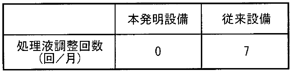
- a conventional detoxification facility that manages aqueous solutions individually is treated with treatment solution or NaOH aqueous solution and Na S O
- Table 1 shows the results of comparison of the number of treatment liquid adjustments per month for 2 2 3 aqueous solutions. As shown in Table 1, the number of adjustments is remarkably reduced by using pre-prepared processing solutions.
- Table 1 shows the number of adjustments of the treatment liquid per month when the treatment liquid is used to detoxify the detoxification facility 10 shown in FIG.
- a treatment solution containing 1 to 1.5 times the Na 2 S 2 O aqueous solution was prepared with respect to the theoretical amount necessary for detoxifying the chlorine-containing component contained in the exhaust gas.
- Table 3 shows the measured COD value of the waste liquid in the drain pit 230 when the treatment liquid was used to perform the detoxification process in the detoxification facility 10 shown in FIG.
- the COD value was also measured in the case of using the treatment liquid prepared by increasing the amount of Na SO aqueous solution to 1.5 to 2.5 times the theoretical value, and the results are also shown in Table 3. .
- the wastewater COD value was suppressed to 100 or less. If the amount of Na 2 S 2 O aqueous solution is less than the theoretical amount, unreacted chlorine-containing components remain in the exhaust gas, which is not preferable.
- a processing solution was prepared by adding 1 to 3 times the molar amount of NaOH with respect to the amount of Na 2 SO added to the processing solution.
- the other conditions were the same as in Example 2, and the detoxification treatment of exhaust gas was performed using the detoxification facility 10 shown in FIG. For comparison, the same detoxification treatment was performed when the NaOH ratio was increased 3 to 5 times.
- Table 4 shows the number of adjustments per month for each treatment. [Table 4]
- the amount of Na S O aqueous solution used is 1 to 1.5 times the theoretical amount required for chlorine detoxification, and Na Na
- the amount of OH aqueous solution added is 1 to 3 times that of Na S O in moles.
- Example 2 Were mixed to prepare a treatment solution.
- the other conditions were the same as in Example 1, and the treatment liquid was used to detoxify the exhaust gas.
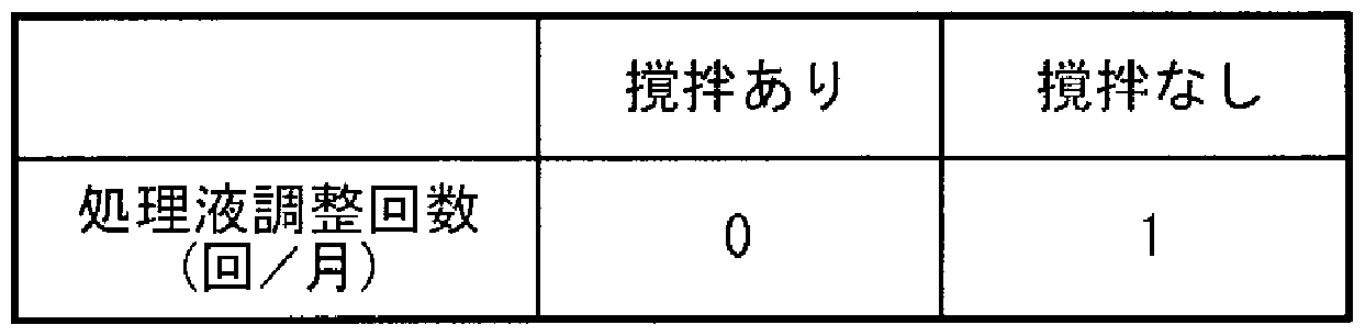
- Table 2 shows the number of adjustments of the treatment liquid per month for the case where the detoxification treatment was carried out under the same conditions except that the treatment liquid prepared without mixing with a stirrer was used.
- Treatment liquid adjustment times per month for treatment liquid or NaOH aqueous solution and Na S O aqueous solution were used.
- Table 5 shows the results of comparison by number.
- Table 5 also shows the results of the detoxification process using the conventional method, which is the object of comparison in Example 1. As shown in Table 5, the number of adjustments is significantly reduced by using a pre-prepared processing solution.
- FIG. 2 is a diagram schematically showing the structure of the detoxification facility 20 according to another embodiment. As shown in the figure, the exhaust gas is sent to a chlorination facility 210. Chlorine removal equipment 210 A mixture of water and treatment liquid is sprayed on the gas.
- the detoxification facility 20 includes a mixing facility 310 for preparing the treatment liquid.
- a mixing facility 310 for preparing the treatment liquid.
- NaOH aqueous solution and Na S O aqueous solution are mixed at a predetermined ratio.
- the obtained treatment liquid is supplied by a pump 320 to 210 kg of chlorine removal equipment.
- the treated liquid after the reaction is circulated by the pump 220 and sprayed again into the chlorine abatement equipment 210. Furthermore, a part of the processing liquid is discharged into the drain pit 230 as waste liquid after the reaction.
- the residual Na S O level is stable at a maximum of 0.05%.
- the detoxification process could be continued without adjusting the amount of Na S O input.
- Figure 2 shows the transition of 2 2 3 distillate.
- Example 6 For comparison, the measurement results of Example 6 are shown together with the scale of FIG. As shown in the figure, the amount of residual Na 2 SO The dispersion of the sword was significantly reduced, and it was strong that it would not exceed 0.05% from beginning to end.
- the amount of Na S O aqueous solution used was 1 to 1.5 times the theoretical amount required for detoxifying chlorine.
- the detoxification treatment of exhaust gas was performed using the detoxification equipment 20 shown in FIG. 2 under the same conditions as in Example 7.
- the input amount of Na S O aqueous solution is the theoretical amount of 1.5-2.
- the detoxification treatment was also performed in the same way even when increased to 5 times.
- detoxification processing was performed in the conventional method using the conventional method.
- the wastewater COD value of the wastewater discharged into the drainage pit 230 was measured, and the transition is shown in the graph of Fig.5.
- acidic exhaust gas containing chlorine can be efficiently and reliably rendered harmless.
- COD values can be reliably reduced for wastewater generated by detoxification. Therefore, it is possible to manufacture a synthetic quartz glass base material, which is a material for optical fibers and the like, which is in increasing demand, under a low environmental load.
Landscapes
- Chemical & Material Sciences (AREA)
- Engineering & Computer Science (AREA)
- Chemical Kinetics & Catalysis (AREA)
- Materials Engineering (AREA)
- Manufacturing & Machinery (AREA)
- Organic Chemistry (AREA)
- General Chemical & Material Sciences (AREA)
- Health & Medical Sciences (AREA)
- Geochemistry & Mineralogy (AREA)
- General Life Sciences & Earth Sciences (AREA)
- Life Sciences & Earth Sciences (AREA)
- Biomedical Technology (AREA)
- Environmental & Geological Engineering (AREA)
- Analytical Chemistry (AREA)
- Oil, Petroleum & Natural Gas (AREA)
- Treating Waste Gases (AREA)
- Manufacture, Treatment Of Glass Fibers (AREA)
- Glass Melting And Manufacturing (AREA)
Abstract
Description



Claims
Applications Claiming Priority (4)
| Application Number | Priority Date | Filing Date | Title |
|---|---|---|---|
| JP2004261222 | 2004-09-08 | ||
| JP2004-261222 | 2004-09-08 | ||
| JP2005-011718 | 2005-01-19 | ||
| JP2005011718A JP2006102735A (ja) | 2004-09-08 | 2005-01-19 | 排ガスの無害化方法及びこれに用いる設備 |
Publications (1)
| Publication Number | Publication Date |
|---|---|
| WO2006027889A1 true WO2006027889A1 (ja) | 2006-03-16 |
Family
ID=36036183
Family Applications (1)
| Application Number | Title | Priority Date | Filing Date |
|---|---|---|---|
| PCT/JP2005/012507 Ceased WO2006027889A1 (ja) | 2004-09-08 | 2005-07-06 | 無害化方法およびその実施に用いる設備 |
Country Status (3)
| Country | Link |
|---|---|
| JP (1) | JP2006102735A (ja) |
| TW (1) | TW200609192A (ja) |
| WO (1) | WO2006027889A1 (ja) |
Cited By (1)
| Publication number | Priority date | Publication date | Assignee | Title |
|---|---|---|---|---|
| CN101322904B (zh) * | 2008-07-16 | 2010-12-08 | 中国科学技术大学 | 一种氯气洗消剂 |
Citations (4)
| Publication number | Priority date | Publication date | Assignee | Title |
|---|---|---|---|---|
| JPS5978942A (ja) * | 1982-10-22 | 1984-05-08 | Furukawa Electric Co Ltd:The | 光フアイバ母材製造系における排ガス処理方法 |
| JPH0796133A (ja) * | 1993-09-27 | 1995-04-11 | Sumitomo Electric Ind Ltd | 塩素ガスを含有する排ガスの処理方法及び処理装置 |
| JP2000271437A (ja) * | 1999-03-24 | 2000-10-03 | Ebara Corp | 排ガスの処理方法および装置 |
| JP2004305799A (ja) * | 2003-04-02 | 2004-11-04 | Sumitomo Electric Ind Ltd | 排気ガスの処理方法 |
-
2005
- 2005-01-19 JP JP2005011718A patent/JP2006102735A/ja active Pending
- 2005-07-06 WO PCT/JP2005/012507 patent/WO2006027889A1/ja not_active Ceased
- 2005-07-20 TW TW094124466A patent/TW200609192A/zh unknown
Patent Citations (4)
| Publication number | Priority date | Publication date | Assignee | Title |
|---|---|---|---|---|
| JPS5978942A (ja) * | 1982-10-22 | 1984-05-08 | Furukawa Electric Co Ltd:The | 光フアイバ母材製造系における排ガス処理方法 |
| JPH0796133A (ja) * | 1993-09-27 | 1995-04-11 | Sumitomo Electric Ind Ltd | 塩素ガスを含有する排ガスの処理方法及び処理装置 |
| JP2000271437A (ja) * | 1999-03-24 | 2000-10-03 | Ebara Corp | 排ガスの処理方法および装置 |
| JP2004305799A (ja) * | 2003-04-02 | 2004-11-04 | Sumitomo Electric Ind Ltd | 排気ガスの処理方法 |
Cited By (1)
| Publication number | Priority date | Publication date | Assignee | Title |
|---|---|---|---|---|
| CN101322904B (zh) * | 2008-07-16 | 2010-12-08 | 中国科学技术大学 | 一种氯气洗消剂 |
Also Published As
| Publication number | Publication date |
|---|---|
| JP2006102735A (ja) | 2006-04-20 |
| TW200609192A (en) | 2006-03-16 |
Similar Documents
| Publication | Publication Date | Title |
|---|---|---|
| JP5637713B2 (ja) | 排水の処理方法及び処理装置 | |
| US7938766B2 (en) | Calcium-sodium polysulfide chemical reagent and production methods | |
| CN107013924B (zh) | 垃圾焚烧飞灰处理设备及处理方法 | |
| WO1999044689A1 (en) | Stabilization of lead bearing waste | |
| KR102027999B1 (ko) | 친환경성 및 고액 분리 성능이 개선된 암모늄계 불소화합물 함유 폐액의 처리방법 | |
| JP4107688B2 (ja) | ゲルマニウムを回収するための光ファイバプリフォーム製造装置の気体廃棄物の処理方法 | |
| CN106311719B (zh) | 一种电石渣的回收利用方法 | |
| WO2006118280A1 (ja) | ヨウ素の回収方法 | |
| CN1736560A (zh) | 废水、废气、余热综合治理、利用的方法 | |
| KR102282158B1 (ko) | 탈황 폐기물의 중금속 용출 억제 조성물 및 이를 이용한 탈황 폐기물의 중금속 용출 억제 방법 | |
| CN104817118A (zh) | 一种简单快速制备聚合氯化铁的方法 | |
| KR101086076B1 (ko) | 암모니아 폐수의 처리방법 | |
| JP5895035B2 (ja) | 高反応性消石灰およびその製造方法、並びに排ガス処理剤 | |
| JPH0796133A (ja) | 塩素ガスを含有する排ガスの処理方法及び処理装置 | |
| JP4584185B2 (ja) | ホウ素含有排水の処理方法及び処理装置 | |
| KR100442924B1 (ko) | 중금속 안정화제 및 이를 이용하여 중금속 함유 폐기물을안정화하는 방법 | |
| CN114853205B (zh) | 一种焦化硫泡沫制酸过程中产生稀硫酸的无害化处理方法 | |
| CN108658305A (zh) | 一种微量氨氮的处理方法 | |
| KR20050006517A (ko) | 폐수 내 암모니아성 질소의 제거방법 | |
| CN101602488A (zh) | 用电石渣处理氯水制备漂白粉和无水氯化钙的方法 | |
| CN212387878U (zh) | 一种磷化工废水末端高效处理氨氮和cod的装置 | |
| KR100318661B1 (ko) | 하폐수처리제및그의처리방법 | |
| CN108211754A (zh) | 一种烟气污染物吸收剂及其应用 | |
| JP2006102735A (ja) | 排ガスの無害化方法及びこれに用いる設備 | |
| KR102771739B1 (ko) | Boe 폐액의 처리방법 |
Legal Events
| Date | Code | Title | Description |
|---|---|---|---|
| AK | Designated states |
Kind code of ref document: A1 Designated state(s): AE AG AL AM AT AU AZ BA BB BG BR BW BY BZ CA CH CN CO CR CU CZ DE DK DM DZ EC EE EG ES FI GB GD GE GH GM HR HU ID IL IN IS KE KG KM KP KR KZ LC LK LR LS LT LU LV MA MD MG MK MN MW MX MZ NA NG NI NO NZ OM PG PH PL PT RO RU SC SD SE SG SK SL SM SY TJ TM TN TR TT TZ UA UG US UZ VC VN YU ZA ZM ZW |
|
| AL | Designated countries for regional patents |
Kind code of ref document: A1 Designated state(s): BW GH GM KE LS MW MZ NA SD SL SZ TZ UG ZM ZW AM AZ BY KG KZ MD RU TJ TM AT BE BG CH CY CZ DE DK EE ES FI FR GB GR HU IE IS IT LT LU LV MC NL PL PT RO SE SI SK TR BF BJ CF CG CI CM GA GN GQ GW ML MR NE SN TD TG |
|
| 121 | Ep: the epo has been informed by wipo that ep was designated in this application | ||
| NENP | Non-entry into the national phase |
Ref country code: DE |
|
| 122 | Ep: pct application non-entry in european phase |