WO2005123879A1 - Flüssigkristallines medium - Google Patents
Flüssigkristallines medium Download PDFInfo
- Publication number
- WO2005123879A1 WO2005123879A1 PCT/EP2005/006428 EP2005006428W WO2005123879A1 WO 2005123879 A1 WO2005123879 A1 WO 2005123879A1 EP 2005006428 W EP2005006428 W EP 2005006428W WO 2005123879 A1 WO2005123879 A1 WO 2005123879A1
- Authority
- WO
- WIPO (PCT)
- Prior art keywords
- compounds
- formulas
- liquid
- crystalline medium
- medium according
- Prior art date
Links
- 0 *c(cc1)ccc1-c(cc1)ccc1-c1ccc(-c(cc2F)cc(F)c2OC(F)(F)F)c(F)c1 Chemical compound *c(cc1)ccc1-c(cc1)ccc1-c1ccc(-c(cc2F)cc(F)c2OC(F)(F)F)c(F)c1 0.000 description 8
- ACRINFORRKOCHJ-UHFFFAOYSA-N CC(CC1)CCC1c(cc1)ccc1N Chemical compound CC(CC1)CCC1c(cc1)ccc1N ACRINFORRKOCHJ-UHFFFAOYSA-N 0.000 description 1
Classifications
-
- C—CHEMISTRY; METALLURGY
- C09—DYES; PAINTS; POLISHES; NATURAL RESINS; ADHESIVES; COMPOSITIONS NOT OTHERWISE PROVIDED FOR; APPLICATIONS OF MATERIALS NOT OTHERWISE PROVIDED FOR
- C09K—MATERIALS FOR MISCELLANEOUS APPLICATIONS, NOT PROVIDED FOR ELSEWHERE
- C09K19/00—Liquid crystal materials
- C09K19/04—Liquid crystal materials characterised by the chemical structure of the liquid crystal components, e.g. by a specific unit
- C09K19/42—Mixtures of liquid crystal compounds covered by two or more of the preceding groups C09K19/06 - C09K19/40
- C09K19/44—Mixtures of liquid crystal compounds covered by two or more of the preceding groups C09K19/06 - C09K19/40 containing compounds with benzene rings directly linked
-
- C—CHEMISTRY; METALLURGY
- C09—DYES; PAINTS; POLISHES; NATURAL RESINS; ADHESIVES; COMPOSITIONS NOT OTHERWISE PROVIDED FOR; APPLICATIONS OF MATERIALS NOT OTHERWISE PROVIDED FOR
- C09K—MATERIALS FOR MISCELLANEOUS APPLICATIONS, NOT PROVIDED FOR ELSEWHERE
- C09K19/00—Liquid crystal materials
- C09K19/04—Liquid crystal materials characterised by the chemical structure of the liquid crystal components, e.g. by a specific unit
- C09K19/06—Non-steroidal liquid crystal compounds
- C09K19/08—Non-steroidal liquid crystal compounds containing at least two non-condensed rings
- C09K19/10—Non-steroidal liquid crystal compounds containing at least two non-condensed rings containing at least two benzene rings
- C09K19/12—Non-steroidal liquid crystal compounds containing at least two non-condensed rings containing at least two benzene rings at least two benzene rings directly linked, e.g. biphenyls
-
- C—CHEMISTRY; METALLURGY
- C09—DYES; PAINTS; POLISHES; NATURAL RESINS; ADHESIVES; COMPOSITIONS NOT OTHERWISE PROVIDED FOR; APPLICATIONS OF MATERIALS NOT OTHERWISE PROVIDED FOR
- C09K—MATERIALS FOR MISCELLANEOUS APPLICATIONS, NOT PROVIDED FOR ELSEWHERE
- C09K19/00—Liquid crystal materials
- C09K19/04—Liquid crystal materials characterised by the chemical structure of the liquid crystal components, e.g. by a specific unit
- C09K19/42—Mixtures of liquid crystal compounds covered by two or more of the preceding groups C09K19/06 - C09K19/40
-
- C—CHEMISTRY; METALLURGY
- C09—DYES; PAINTS; POLISHES; NATURAL RESINS; ADHESIVES; COMPOSITIONS NOT OTHERWISE PROVIDED FOR; APPLICATIONS OF MATERIALS NOT OTHERWISE PROVIDED FOR
- C09K—MATERIALS FOR MISCELLANEOUS APPLICATIONS, NOT PROVIDED FOR ELSEWHERE
- C09K19/00—Liquid crystal materials
- C09K19/04—Liquid crystal materials characterised by the chemical structure of the liquid crystal components, e.g. by a specific unit
- C09K2019/0444—Liquid crystal materials characterised by the chemical structure of the liquid crystal components, e.g. by a specific unit characterized by a linking chain between rings or ring systems, a bridging chain between extensive mesogenic moieties or an end chain group
- C09K2019/0448—Liquid crystal materials characterised by the chemical structure of the liquid crystal components, e.g. by a specific unit characterized by a linking chain between rings or ring systems, a bridging chain between extensive mesogenic moieties or an end chain group the end chain group being a polymerizable end group, e.g. -Sp-P or acrylate
-
- C—CHEMISTRY; METALLURGY
- C09—DYES; PAINTS; POLISHES; NATURAL RESINS; ADHESIVES; COMPOSITIONS NOT OTHERWISE PROVIDED FOR; APPLICATIONS OF MATERIALS NOT OTHERWISE PROVIDED FOR
- C09K—MATERIALS FOR MISCELLANEOUS APPLICATIONS, NOT PROVIDED FOR ELSEWHERE
- C09K19/00—Liquid crystal materials
- C09K19/04—Liquid crystal materials characterised by the chemical structure of the liquid crystal components, e.g. by a specific unit
- C09K2019/0444—Liquid crystal materials characterised by the chemical structure of the liquid crystal components, e.g. by a specific unit characterized by a linking chain between rings or ring systems, a bridging chain between extensive mesogenic moieties or an end chain group
- C09K2019/0451—Liquid crystal materials characterised by the chemical structure of the liquid crystal components, e.g. by a specific unit characterized by a linking chain between rings or ring systems, a bridging chain between extensive mesogenic moieties or an end chain group the end chain group being a CH3CH=CHCH2CH2- chain
-
- C—CHEMISTRY; METALLURGY
- C09—DYES; PAINTS; POLISHES; NATURAL RESINS; ADHESIVES; COMPOSITIONS NOT OTHERWISE PROVIDED FOR; APPLICATIONS OF MATERIALS NOT OTHERWISE PROVIDED FOR
- C09K—MATERIALS FOR MISCELLANEOUS APPLICATIONS, NOT PROVIDED FOR ELSEWHERE
- C09K19/00—Liquid crystal materials
- C09K19/04—Liquid crystal materials characterised by the chemical structure of the liquid crystal components, e.g. by a specific unit
- C09K2019/0444—Liquid crystal materials characterised by the chemical structure of the liquid crystal components, e.g. by a specific unit characterized by a linking chain between rings or ring systems, a bridging chain between extensive mesogenic moieties or an end chain group
- C09K2019/0466—Liquid crystal materials characterised by the chemical structure of the liquid crystal components, e.g. by a specific unit characterized by a linking chain between rings or ring systems, a bridging chain between extensive mesogenic moieties or an end chain group the linking chain being a -CF2O- chain
-
- C—CHEMISTRY; METALLURGY
- C09—DYES; PAINTS; POLISHES; NATURAL RESINS; ADHESIVES; COMPOSITIONS NOT OTHERWISE PROVIDED FOR; APPLICATIONS OF MATERIALS NOT OTHERWISE PROVIDED FOR
- C09K—MATERIALS FOR MISCELLANEOUS APPLICATIONS, NOT PROVIDED FOR ELSEWHERE
- C09K19/00—Liquid crystal materials
- C09K19/04—Liquid crystal materials characterised by the chemical structure of the liquid crystal components, e.g. by a specific unit
- C09K19/06—Non-steroidal liquid crystal compounds
- C09K19/08—Non-steroidal liquid crystal compounds containing at least two non-condensed rings
- C09K19/10—Non-steroidal liquid crystal compounds containing at least two non-condensed rings containing at least two benzene rings
- C09K19/12—Non-steroidal liquid crystal compounds containing at least two non-condensed rings containing at least two benzene rings at least two benzene rings directly linked, e.g. biphenyls
- C09K2019/121—Compounds containing phenylene-1,4-diyl (-Ph-)
- C09K2019/123—Ph-Ph-Ph
-
- C—CHEMISTRY; METALLURGY
- C09—DYES; PAINTS; POLISHES; NATURAL RESINS; ADHESIVES; COMPOSITIONS NOT OTHERWISE PROVIDED FOR; APPLICATIONS OF MATERIALS NOT OTHERWISE PROVIDED FOR
- C09K—MATERIALS FOR MISCELLANEOUS APPLICATIONS, NOT PROVIDED FOR ELSEWHERE
- C09K19/00—Liquid crystal materials
- C09K19/04—Liquid crystal materials characterised by the chemical structure of the liquid crystal components, e.g. by a specific unit
- C09K19/06—Non-steroidal liquid crystal compounds
- C09K19/08—Non-steroidal liquid crystal compounds containing at least two non-condensed rings
- C09K19/10—Non-steroidal liquid crystal compounds containing at least two non-condensed rings containing at least two benzene rings
- C09K19/12—Non-steroidal liquid crystal compounds containing at least two non-condensed rings containing at least two benzene rings at least two benzene rings directly linked, e.g. biphenyls
- C09K2019/121—Compounds containing phenylene-1,4-diyl (-Ph-)
- C09K2019/124—Ph-Ph-Ph-Ph
-
- C—CHEMISTRY; METALLURGY
- C09—DYES; PAINTS; POLISHES; NATURAL RESINS; ADHESIVES; COMPOSITIONS NOT OTHERWISE PROVIDED FOR; APPLICATIONS OF MATERIALS NOT OTHERWISE PROVIDED FOR
- C09K—MATERIALS FOR MISCELLANEOUS APPLICATIONS, NOT PROVIDED FOR ELSEWHERE
- C09K19/00—Liquid crystal materials
- C09K19/04—Liquid crystal materials characterised by the chemical structure of the liquid crystal components, e.g. by a specific unit
- C09K19/06—Non-steroidal liquid crystal compounds
- C09K19/32—Non-steroidal liquid crystal compounds containing condensed ring systems, i.e. fused, bridged or spiro ring systems
- C09K2019/327—Non-steroidal liquid crystal compounds containing condensed ring systems, i.e. fused, bridged or spiro ring systems containing a spiro ring system
-
- C—CHEMISTRY; METALLURGY
- C09—DYES; PAINTS; POLISHES; NATURAL RESINS; ADHESIVES; COMPOSITIONS NOT OTHERWISE PROVIDED FOR; APPLICATIONS OF MATERIALS NOT OTHERWISE PROVIDED FOR
- C09K—MATERIALS FOR MISCELLANEOUS APPLICATIONS, NOT PROVIDED FOR ELSEWHERE
- C09K2323/00—Functional layers of liquid crystal optical display excluding electroactive liquid crystal layer characterised by chemical composition
Definitions
- the present invention relates to a liquid-crystalline medium, its use for electro-optical purposes and displays containing this medium.
- Liquid crystals are mainly used as dielectrics in display devices, since the optical properties of such substances can be influenced by an applied voltage.
- Electro-optical devices based on liquid crystals are well known to the person skilled in the art and can be based on various effects. Such devices are, for example, cells with dynamic scattering, DAP cells (deformation of aligned phases), guest / host cells, TN cells with a twisted nematic ("twisted nematic") structure, STN cells (“super-twisted nematic”), SBE cells (“superbirefringence effect”) and OMI cells ("optical mode interference”).
- the most common display devices are based on the Schadt-Helfrich effect and have a twisted nematic structure.
- the liquid crystal materials must have good chemical and thermal stability and good stability against electric fields and electromagnetic radiation. Furthermore, the liquid crystal materials should have a low viscosity and give short response times, low threshold voltages and a high contrast in the cells.
- nematic or cholesteric mesophase for the above-mentioned cells.
- liquid crystals are generally used as mixtures of several components, it is important that the components are readily miscible with one another.
- Other properties, such as electrical conductivity, dielectric anisotropy and optical anisotropy, must meet different requirements depending on the cell type and field of application. For example, materials for cells should also be twisted nematic structure have positive dielectric anisotropy and low electrical conductivity.
- media with large positive dielectric anisotropy, wide nematic phases, relatively low birefringence, very high resistivity, good UV and temperature stability and lower vapor pressure are desired for matrix liquid crystal displays with integrated non-linear elements for switching individual pixels (MLC displays).
- OCB displays ("optically compensated bend") are based on a birefringence effect and contain a liquid crystal layer with a so-called “bend” structure.
- the "bend” cell also known as the "pi” cell, was first proposed by P. Bos et al., SID 83 Digest, 30 (1983) for an electrically controllable ⁇ / 2 plate during OCB mode for advertisements by Y. Yamaguchi, T. Miyashita and T. Uchida, SID 93 Digest, 277 (1993), and thereafter in works by T. Miyashita et al. in, inter alia, Proc. Eurodisplay, 149 (1993), J.Appl.Phys.
- An OCB cell contains a liquid crystal cell with "bend" orientation and a liquid crystal medium with positive ⁇ .
- the OCB displays known from the above-mentioned documents contain one or more birefringent optical retardation films in order to avoid undesired light transmission of the "bend" cell in the dark state.
- OCB displays have several advantages over the conventional displays, which are based on twisted nematic (TN) cells, such as a wider viewing angle and shorter switching times.
- TN twisted nematic
- liquid-crystalline phases have high values for the optical anisotropy ⁇ n and a relatively high positive value for the dielectric anisotropy ⁇ and preferably very low values for the ratio of the elastic constants K 33 / K 1 1 and for the viscosity in order to be used for high-information display elements based on the OCB effect.
- LC phases are required, which must meet a multitude of requirements.
- the chemical resistance to moisture, air and physical influences such as heat, radiation in the infrared, visible and ultraviolet range as well as electrical direct and alternating current fields are particularly important here.
- technically usable LC phases require a liquid-crystalline mesophase in a suitable temperature range, a relatively high birefringence, a positive dielectric anisotropy and a low viscosity.
- LCoS TM (Liquid Crystal on Silicon) displays are known in the art and are available from Three-Five Systems Inc. (Tempe, Arizona, USA).
- LCoS TM micro-displays are reflective displays, which typically contain a liquid crystal layer with a twisted nematic structure between a back wall made of silicon and a cover glass.
- the back wall made of silicon is an arrangement of pixels, each of which has a mirror-image surface that also acts as an electrical conductor.
- Each pixel contains a fixed mirror, which is covered by an active liquid crystal layer with a twisted nematic orientation, which can be switched to homeotropic orientation by applying a voltage.
- LCoS TM microdisplays are small with a diagonal of typically less than 1.0 inch, but enable high resolutions from% VGA (78 thousand pixels) to UXGA + (over 2 million pixels).
- LCoS TM displays Due to the small pixel size, LCoS TM displays also have a very small cell thickness, which is typically around 1 micrometer.
- the liquid crystalline phases used in these displays must therefore in particular have high values for the optical anisotropy ⁇ n, in contrast to conventional LC displays of the reflective type, which normally require LC phases with a low ⁇ n.
- OCB mode and LCoS TM displays can be operated as matrix displays.
- Matrix liquid crystal displays MLC displays
- active elements i.e. transistors
- MOS Metal Oxide Semiconductor
- TFT Thin film transistors
- the TN effect is usually used as the electro-optical effect.
- TFTs made from compound semiconductors such as CdSe or TFT's based on polycrystalline or amorphous silicon The latter technology is being worked on with great intensity worldwide.
- the TFT matrix is applied to the inside of one glass plate of the display, while the other glass plate carries the transparent counter electrode on the inside. Compared to the size of the pixel electrode, the TFT is very small and practically does not disturb the image.
- This technology can also be expanded for full color images, with a mosaic of red, green and blue filters is arranged such that a filter element is opposite a switchable picture element.
- the TFT displays usually work as TN cells with crossed polarizers in transmission and are illuminated from behind.
- MLC displays of this type are particularly suitable for TV applications or for high-information displays for computer applications (laptops) and in automobile or aircraft construction.
- difficulties arise with MLC displays due to insufficiently high specific resistance of the liquid crystal mixtures [TOGASHI, S., SEKIGUCHI, K., TANABE, H., YAMAMOTO, E., SORIMACHI, K. , TAJIMA, E., WATANABE, H., SHIMIZU, H., Proc. Eurodisplay 84, Sept. 1984: A 210-288 Matrix LCD Controlled by Double Stage Diode Rings, p. 141 ff, Paris; STROMER, M., Proc.
- reflective liquid crystal displays are also of particular interest. These reflective liquid crystal displays use ambient light to present information. This means that they consume significantly less energy than backlit liquid crystal displays with the appropriate size and resolution. Since the TN effect is characterized by a very good contrast, such reflective displays can still be read well even in bright ambient conditions. This is already from simple reflective TN displays as they are in z. B. wristwatches and calculators are known. However, the principle is also based on high-quality, higher-resolution active matrix displays such. B. TFT displays applicable.
- liquid crystals with low birefringence ⁇ n
- d • ⁇ n the optical delay
- This slight optical delay leads to a usually acceptable low viewing angle dependence of the contrast (cf. DE 30 22 818).
- the use of liquid crystals with small birefringence is even more important in the case of reflective displays than in the case of transmissive displays, since the effective layer thickness which the light traverses is approximately twice as large in the case of reflective displays as in the case of transmissive displays with the same layer thickness.
- liquid-crystalline media for MFK, OCB, IPS, TN, LCoS or STN displays which have high UV stability, relatively high ⁇ values, low thresholds and clearing points> 70 ° C.
- TN Schot-Helfrich
- media are desired that enable the following advantages in the cells: Extended nematic phase range (especially at low temperatures) is stable in storage, even at extremely low temperatures
- the object of the invention is to provide media, in particular for such MFK, OCB, IPS, LCoS, TN or STN displays, which do not or only to a lesser extent the disadvantages indicated above, and preferably at the same time have relatively high clearing points , low
- the ⁇ n values should preferably be> 0.07, particularly preferably> 0.08.
- the mixtures should also be distinguished by high UV stability. It has now been found that this object can be achieved if media according to the invention are used in advertisements.
- the media according to the invention are distinguished by relatively high dielectric anisotropies and clearing points. At the same time, the media have very low threshold voltages and relatively low rotational viscosities y ⁇ ⁇ and excellent UV stability.
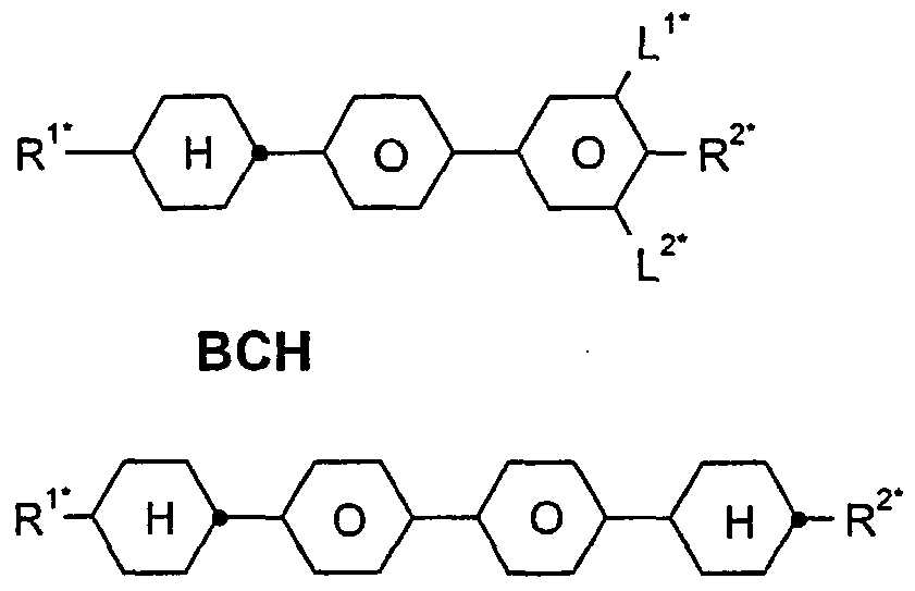
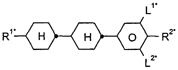
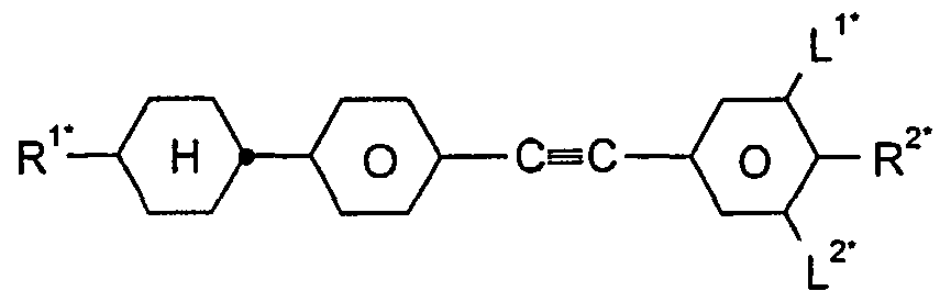
- the invention thus relates to a liquid-crystalline medium based on a mixture of polar compounds, characterized in that it contains one or more compounds of the formula I.
- X, X A , and X B each independently of one another F, Cl, CN, SF 5 , SCN, NCS, halogenated alkyl radical, halogenated alkenyl radical, halogenated alkoxy radical or halogenated alkenyloxy radical with up to 6 carbon atoms,
- liquid-crystalline mixtures comprising compounds of the formulas I and IA, IB and / or IC have relatively high clearing points, low thresholds and ⁇ n values, preferably of> 0.07, in particular> 0.08.
- X preferably denotes CN, F, SF 5 , OCHF 2) OC 2 F 5 , OC 3 F 7 , NCS, OCHFCF3, OCF 2 CHFCF 3 , OCF 3 .
- WO 2004/0357 10 A1 describes compounds of the formula
- Base materials from other classes of compounds are added, for example, to influence the dielectric and / or optical anisotropy of such a dielectric and / or to optimize its threshold voltage and / or its viscosity.
- the quad-cores according to the invention are very readily soluble.
- the influence of the compound of the formula I, in particular on the VHR under UV exposure, on the mixing concept according to the invention can already be determined when the compound of the formula I is present in concentrations of ⁇ 1%.
- the compounds of the formulas I, IA, IB and / or IC are colorless in the pure state and form liquid-crystalline mesophases in a temperature range which is conveniently located for electro-optical use. They are stable chemically, thermally and against light.
- R 1 , R 1A , R 1B and / or R 1C is an alkyl radical and / or an alkoxy radical, this can be straight-chain or branched. It is preferably straight-chain, has 2, 3, 4, 5, 6 or 7 carbon atoms and accordingly preferably means ethyl, propyl, butyl, pentyl, hexyl, heptyl, ethoxy, propoxy,
- R, R A , R 1B and / or R 1C is an alkyl radical in which a 1
- R 1 , R 1A , R 1B and / or R 1C is an alkyl radical in which one CH 2 group is replaced by -O- and one is replaced by -CO-, these are preferably adjacent. Thus, these include an acyloxy group -CO-O- or an oxycarbonyl group -0-CO-. These are preferably straight-chain and have 2 to 6 carbon atoms.
- it means especially acryloyloxymethyl, 2-acryloyl-oxyethyl, 3-acryloyloxypropyl, 4-acryloyloxy-butyl, 5-acryloyloxypentyl, 6-acryloyloxyhexyl, 7-acryloyloxyheptyl, 8-acryloyloxyoctyl, 9-acryloyl-oxynonyl, 10-acryloyloxyloxyloxyl 2-methacryloyloxyethyl, 3-methacryloyloxypropyl, 4-methacryloyloxybutyl, 5-methacryloyloxypentyl, 6-methacryloyloxyhexyl, 7-methacryloyloxyheptyl, 8-methacryloyloxyoctyl, 9-methacryloyloxynonyl.
- R 1 , R 1A , R 1B and / or R 1C is an alkyl or alkenyl radical which is simply substituted by CN or CF 3 , this radical is preferably straight-chain. The substitution by CN or CF 3 is in any position.
- R 1 , R 1A , R 1B and / or R 1C is an alkyl or alkenyl radical which is at least monosubstituted by halogen
- this radical is preferably straight-chain and halogen is preferably F or Cl.
- halogen is preferably F.
- the resulting residues also include perfluorinated residues.
- the fluorine or chlorine substituent can be in any position, but preferably in the ⁇ position.
- Branched groups of this type usually contain no more than one chain branch.
- R 1 , R 1A , R 1B and / or R 1C represents an alkyl radical in which two or more CH 2 groups have been replaced by -O- and / or -CO-O-, this can be straight-chain or branched. It is preferably branched and has 3 to 12 carbon atoms.
- it means especially bis-carboxymethyl, 2,2-bis-carboxy-ethyl, 3,3-bis-carboxypropyl, 4,4-bis-carboxy-butyl, 5,5-bis-carboxy-pentyl, 6,6-bis-carboxy-hexyl, 7,7-bis-carboxy-heptyl, 8,8-bis-carboxy-octyl, 9,9-bis-carboxy-nonyl, 10,10-bis-carboxy-decyl, Bis (methoxycarbonyl) methyl, 2,2-bis (methoxycarbonyl) ethyl, 3,3-bis (methoxycarbonyl) propyl, 4,4-bis (methoxycarbonyl) butyl, 5,5-bis (methoxycarbonyl) pentyl, 6,6-bis (methoxycarbonyl) - hexyl, 7,7-bis (methoxycarbonyl) heptyl, 8,8-
- X, X A and X b in the compounds of the formulas I, IA and IB independently of one another are preferably F, Cl, CN, NCS, CF 3 , C 2 F 5 , C 3 F, SF 5 , CF 2 H, OCF3, OCF 2 H, OCFHCF3, OCFHCFH2, OCFHCF 2 H, OCF 2 CH 3, OCF 2 CFH 2, OCF 2 CF 2 H, OCF 2 CF2CF2H, OCF 2 CF 2 CFH 2, OCFHCF 2 CF 3, OCFHCF 2 CF 2 H, OCFHCFHCF3, OCH 2 CF 2 CF 3, OCF2CF2CF 3, OCF 2 CFHCFH2, OCF 2 CH 2 CF 2 H, OCFHCF 2 CFH 2, OCFHCFHCF 2 H, OCFHCH 2 CF 3) OCH2CFHCF3, OCH 2 CF 2 CF 2 H, OCF 2 CFHCH 3 , OCF 2 CH 2
- the compounds of the formulas I are prepared by methods known per se, as described in the literature (for example in the standard works such as Houben-Weyl, Methods of Organic Chemistry, Georg-Thieme-Verlag, Stuttgart), and under reaction conditions who are known and suitable for the implementations mentioned. Use can also be made of variants which are known per se and are not mentioned here in detail.
- the compounds of the formula I can be prepared, for example, as follows:
- the invention also relates to electro-optical displays, such as. B. STN or MFK displays with two plane-parallel carrier plates that form a cell with a border, integrated non-linear elements for switching individual pixels on the carrier plates and a nematic liquid crystal mixture in the cell with positive dielectric anisotropy and high specific resistance) which contain such media and the use of these media for electro-optical purposes.
- electro-optical displays such as. B. STN or MFK displays with two plane-parallel carrier plates that form a cell with a border, integrated non-linear elements for switching individual pixels on the carrier plates and a nematic liquid crystal mixture in the cell with positive dielectric anisotropy and high specific resistance
- liquid crystal mixtures according to the invention allow a significant expansion of the available parameter space.
- achievable combinations of clearing point, viscosity at low temperature, thermal and UV stability and high optical anisotropy far exceed previous materials from the prior art.
- the mixtures according to the invention are particularly suitable for fast-switching monitors, TV sets, TV monitor combination devices and high ⁇ n TFT applications, such as, for. B. projection television, LCoS and OCB, suitable.
- the liquid crystal mixtures according to the invention make it possible, while maintaining the nematic phase, to -20 ° C. and preferably to -30 ° C., particularly preferably to -40 ° C., clearing point above 60 ° C., preferably above 70 ° C., particularly preferably above 75 ° C. at the same time to achieve dielectric anisotropy values ⁇ > 4, preferably> 5 and a high value for the specific resistance, as a result of which excellent STN and MFK displays can be achieved.
- the mixtures are characterized by small operating voltages.
- the TN thresholds are below 2.5 V, preferably below 2.0 V, particularly preferably ⁇ 1.8 V.
- the MFK displays according to the invention preferably operate in the first transmission minimum according to Gooch and Tarry [CH. Gooch and HA Tarry, Electron. Lett. 10, 2-4, 1974; CH. Gooch and HA Tarry, Appl. Phys., Vol.
- the flow viscosity at 20 ° C. is preferably ⁇ 60 mm 2 s "1 , particularly preferably ⁇ 50 mm 2 -s ' 1.
- the rotational viscosity ⁇ i of the mixtures according to the invention at 20 ° C is preferably ⁇ 130 mPa-s, particularly preferably ⁇ 100
- the nematic phase range is preferably at least 90 °, in particular at least 100 °, This range preferably extends at least from -20 ° to + 80 °.
- a short switching time is desirable for liquid crystal displays. This is especially true for ads that are capable of video playback. Such displays require switching times (total: t on + W of a maximum of 25 ms. The upper limit of the switching time is determined by the refresh rate. In addition to the rotational viscosity ⁇ i, the tilt angle also influences the switching time.
- the UV stability of the mixtures according to the invention is considerably better, i.e. they show a significantly smaller decrease in HR under UV exposure. Even small concentrations of the compounds ( ⁇ 10% by weight) of the formula I in the mixtures increase the HR by 6% or more compared to mixtures from the prior art.
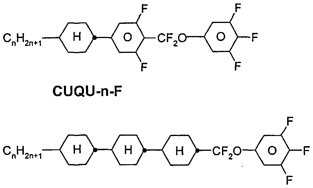
- Particularly preferred compounds of the formula I are compounds of the formulas 1-1 to 1-10,
- R 1 has the meaning given in formula I.
- R 1 is preferably alkyl, furthermore alkenyl.
- R 1 very particularly preferably denotes nC 3 H 7 .
- the medium preferably contains at least one of the following compounds
- the medium preferably contains the compound
- n 3 or 5.
- Particularly preferred compounds of the formula IA are the compounds of the formulas IA-1 to IA-12,
- R A has the meanings given in claim 1.
- R A is preferably straight-chain alkyl, furthermore vinyl and 1 E- or 3E-alkenyl.
- the compounds of the formulas IA-1 to IA-12 are particularly preferred.
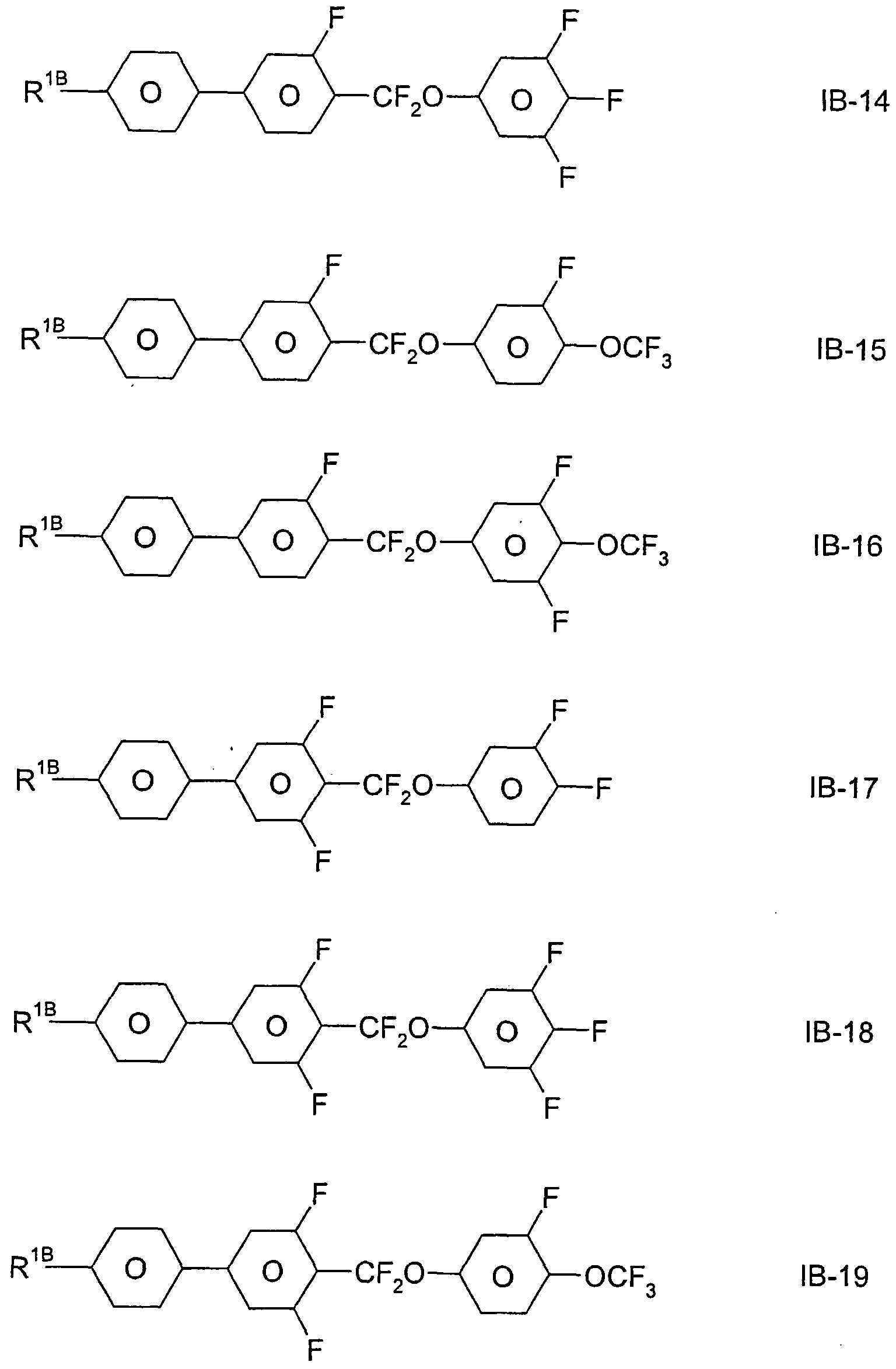
- Preferred compounds of the formulas IB are the compounds of the formulas IB-1 to IB-29,
- R 1B has the meanings given in claim 1.
- R 1B preferably denotes straight-chain alkyl, furthermore vinyl, 1 E- or 3E-alkenyl.
- the compounds of the formula IC-1 and IC-2 are particularly preferred:
- the medium contains one, two or more compounds of the formulas 1-1 to 1-10;
- the medium preferably contains one or more compounds of the formula IA-1 to IA-12;
- the medium contains one, two, three or four connections of the form! IA.
- concentration of the compound (s) of the formula IA in the mixture according to the invention is 2-50% by weight, preferably 2-40% by weight, in particular 5-40% by weight;
- the medium contains one, two, three or four compounds of the formula IB.
- concentration of the compound (s) of the formula IB in the mixture according to the invention is 2-50% by weight, preferably 5-40% by weight;
- the medium contains one, two, three or four compounds of the formula IC.
- concentration of the compound (s) of the formula 1C in the mixture according to the invention is 2-50% by weight, preferably 5-40% by weight;
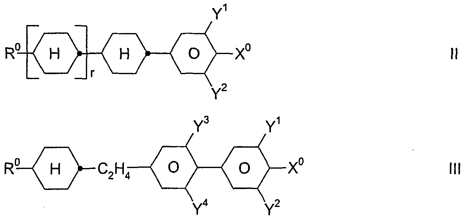
- the medium additionally contains one or more compounds selected from the group consisting of the general formulas
- Y 1 to Y 4 each independently of one another H or F,
- the medium additionally contains one or more compounds selected from the group consisting of the general formulas VII to XII:
- R °, X ° and Y 1 "4 each independently have one of the meanings given in Claim 6.
- X ° is preferably F, Cl, CF 3 , OCF 3 or OCHF 2.
- R ° preferably denotes alkyl,
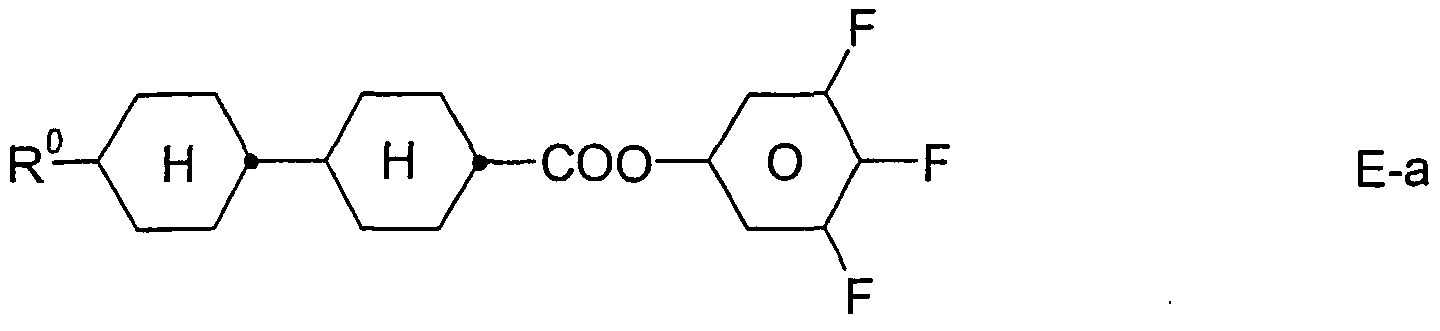
- the medium additionally contains one or more compounds of the
- R ° has the meanings given in claim 6;
- the proportion of the compounds of the formulas E-a and / or E-b is preferably 0-30% by weight, in particular 5-25% by weight;
- the proportion of compounds of the formulas I, IA, IB and / or IC together in the total mixture is at least 10% by weight, preferably> 15% by weight and in particular> 20% by weight;
- the proportion of compounds of the formula I in the total mixture is 0.01 to 30, particularly preferably 0.1 to 20% by weight;
- the proportion of compounds of the formulas II to VI in the mixture as a whole is 10 to 80% by weight;
- the medium contains compounds of the formulas II, III, IV, V and / or VI;
- R ° is straight-chain alkyl or alkenyl with 2 to 7 carbon atoms
- the medium essentially consists of compounds of the formulas I, IA, IB, IC and II-VI, where essentially means> 50% by weight.
- the medium contains further compounds, preferably selected from the following group consisting of the general formulas XIII to XVIII:
- R ° and X ° have the meanings given above.
- X ° preferably denotes F or Cl.
- the concentration of the compounds of the formulas XIII to XVIII is preferably 0.05-30% by weight, in particular 1-25% by weight.
- the medium preferably contains 5-35% by weight of compound IVa.
- the medium preferably contains one, two or three compounds of the formula IVa, in which X ° F or OCF 3 .
- the medium preferably contains one or more compounds of the formulas IIa to IIg,
- R ° has the meanings given above.
- R ° preferably denotes methyl, ethyl, n-propyl, n-butyl and n-pentyl.
- the weight ratio I or I + IA + IB + IC: (II + III + IV + V + VI) is preferably 1:10 to 10: 1.
- the medium essentially consists of compounds selected from the group consisting of the general formulas IA, IB and / or IC and I to XII.
- the proportion of the compounds of the formula IVb, IVc and / or IVd, where X ° is fluorine and R ° is CH 3 , C 2 H 5 , nC 3 H 7 , nC 4 H 9 or nC 5 Hn, is from 2 to 25 in the mixture as a whole % By weight, in particular 2 to 20% by weight.
- the medium preferably contains compounds of the formulas II to VI, in which R ° denotes methyl.
- the medium according to the invention particularly preferably contains compounds of the formulas
- the medium preferably contains one, two or more, preferably one, two or more, dioxane compounds of the formulas D-1 to D-4,
- the proportion of the dioxane compounds D-1 to D-4 in the mixtures according to the invention is preferably 0-40% by weight, in particular 5-35% by weight and very particularly preferably 8-30% by weight.
- the medium additionally contains one, two or more two-core compounds of the formulas Z-1 to Z-9,
- R 1a and R 2a each independently represent H, CH 3 , C 2 H 5 or nC 3 H 7 .
- Alkyl and alkyl * each independently represent a straight-chain or branched alkyl chain with 1-7 C atoms.
- R ° has the meanings given above. In the compounds of the formulas Z-6, Z-7 and Z-9, R ° preferably denotes straight-chain alkyl or alkenyl.
- the compounds of the formulas Z-1, Z-2, Z-5, Z-6, Z-8 and Z-9 are particularly preferred.
- the medium additionally contains one, two or more compounds with fused rings of the formulas AN1 to AN11: where R ° has the meanings given above.
- the proportion of compounds of the formulas AN1 to AN11 in the mixtures according to the invention is preferably 1-20% by weight.
- the mixtures according to the invention are distinguished in particular by the fact that they have clearing points of> 75 ° C. and thresholds of ⁇ 2.0 V.
- alkyl or “alkyl *” encompasses straight-chain and branched alkyl groups having 1-7 carbon atoms, in particular the straight-chain groups methyl, ethyl, propyl, butyl, pentyl, hexyl and heptyl. Groups with 1-6 carbon atoms are generally preferred.
- alkenyl or “alkenyl *" encompasses straight-chain and branched alkenyl groups with 2-7 carbon atoms, in particular the straight-chain groups.
- Preferred alkenyl groups are C 2 -C -1 E-alkenyl, C 4 -C 7 -3E-alkenyl, C 5 -C 7 -4-alkenyl, C 6 -C 7 -5-alkenyl and C 7 -6- alkenyl, in particular C 2 -C 7 -1 E-alkenyl, C 4 -C 7 -3E-alkenyl and C 5 -C - 4-alkenyl.
- alkenyl groups are vinyl, 1 E-propenyl, 1 E-butenyl, 1 E-pentenyl, 1 E-hexenyl, 1 E-heptenyl, 3-butenyl, 3E-pentenyl, 3E-hexenyl, 3E-heptenyl, 4- Pe ⁇ tenyl, 4Z-hexenyl, 4E-hexenyl, 4Z-heptenyl, 5-hexenyl, 6-heptenyl and the like. Groups of up to 5 carbon atoms are generally preferred.
- fluoroalkyl preferably encompasses straight-chain groups with terminal fluorine, i.e. Fluoromethyl, 2-fluoroethyl, 3-fluoropropyl, 4-fluorobutyl, 5-fluoropentyl, 6-fluorhexyl and 7-fluororheptyl. However, other positions of the fluorine are not excluded.
- oxaalkyl or "alkoxy” preferably includes straight-chain radicals of the formula CnH 2n + ⁇ -0- (CH 2 ), in which n and m each independently represent 1 to 6, m can also mean 0.
- a -CH 2 CH 2 group generally leads to higher values of k 33 / kn compared to a simple covalent bond.
- Higher values of k 33 / kn enable, for example, flatter transmission characteristics in TN cells with 90 ° twist (to achieve gray tones) and steeper transmission characteristics in STN, SBE and OMI cells (higher multiplexability) and vice versa.
- the optimal quantitative ratio of the compounds of the formulas IA, IB and / or IC and I + II + III + IV + V + VI largely depends on the desired properties, on the choice of the components of the formulas I, IA, IB, IC, II, III , IV, V and / or VI and the choice of further components which may be present.
- the total amount of compounds of the formulas IA, IB and / or IC and I to XII in the mixtures according to the invention is not critical.
- the mixtures can therefore contain one or more further components in order to optimize various properties.
- the observed effect on the response times and the threshold voltage is generally greater the higher the total concentration of compounds of the formulas IA, IB and / or IC and I to XVIII.
- a favorable synergistic effect with the compounds of the formulas I and IA, IB and / or IC leads to particularly advantageous properties.
- Mixtures containing compounds of the formulas I, IA, IB and / or IC and IVa in particular are notable for their low threshold voltage.
- the individual compounds of the formulas IA, IB and / or IC and I to XVIII and their sub-formulas which can be used in the media according to the invention are either known or they can be prepared analogously to the known compounds.
- Electrode base plates and electrodes with surface treatment correspond to the usual design for such displays.
- the term of the conventional design is broad here and also includes all modifications and modifications of the MLC display, in particular also matrix display elements based on poly-Si TFT or MIM.
- the liquid crystal mixtures which can be used according to the invention are prepared in a manner which is conventional per se.
- the desired amount of the components used in smaller amounts is dissolved in the components which make up the main constituent, advantageously at elevated temperature.
- the dielectrics can also other additives known to the person skilled in the art and described in the literature, such as, for. B.
- UV stabilizers such as Tinuvin ® from Ciba, antioxidants, radical scavengers, etc. contain. For example, 0-15% pleochroic dyes or chiral dopants can be added. Suitable stabilizers and dopants are listed in Tables C and D below.
- C means a crystalline, S a smectic, S c a smectic C, N a nematic and I the isotropic phase.
- V ⁇ denotes the voltage for 10% transmission (viewing direction perpendicular to the plate surface).
- n denotes the switch-on time and t off the switch-off time for an operating voltage corresponding to 2.0 times the value of V ⁇ 0 .
- ⁇ n denotes the optical anisotropy.
- the electro-optical data are measured in a TN cell at the 1st minimum (ie at a d • ⁇ n value of 0.5 ⁇ m) at 20 ° C, unless expressly stated otherwise.
- the optical data are measured at 20 ° C, unless expressly stated otherwise.
- Tables A and B are done. All residues C ⁇ H 2n + ⁇ and C m H 2m + ⁇ are straight-chain alkyl residues with n or m C atoms; n and m are integers and are preferably 0, 1, 2, 3, 4, 5, 6, 7, 8, 9, 10, 11 or 12.
- the coding according to Table B goes without saying.
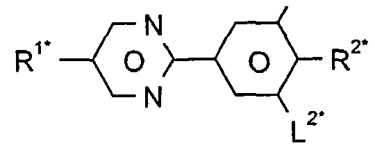
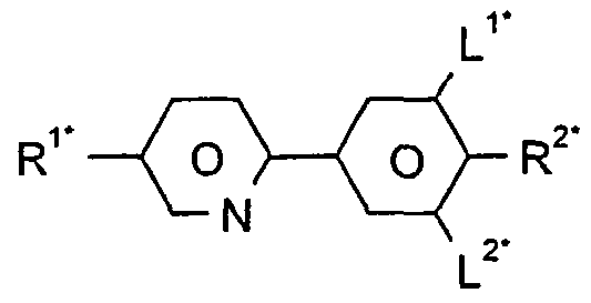
- Table A is only specified the acronym for the base body.
- a code for the substituents R 1 * , R 2 * , L and L 2 * follows separately for the basic body with a rope: Code for R, RR 2 * LL 2 *
- Liquid-crystalline mixtures which, in addition to the compounds of the formulas I, contain at least one, two, three, four or more compounds from Table B are particularly preferred. Table C.
- Table C lists possible dopants which are generally added to the mixtures according to the invention.
- the mixtures preferably contain 0-10% by weight, in particular 0.01-5% by weight and particularly preferably 0.01-3% by weight, of dopants.
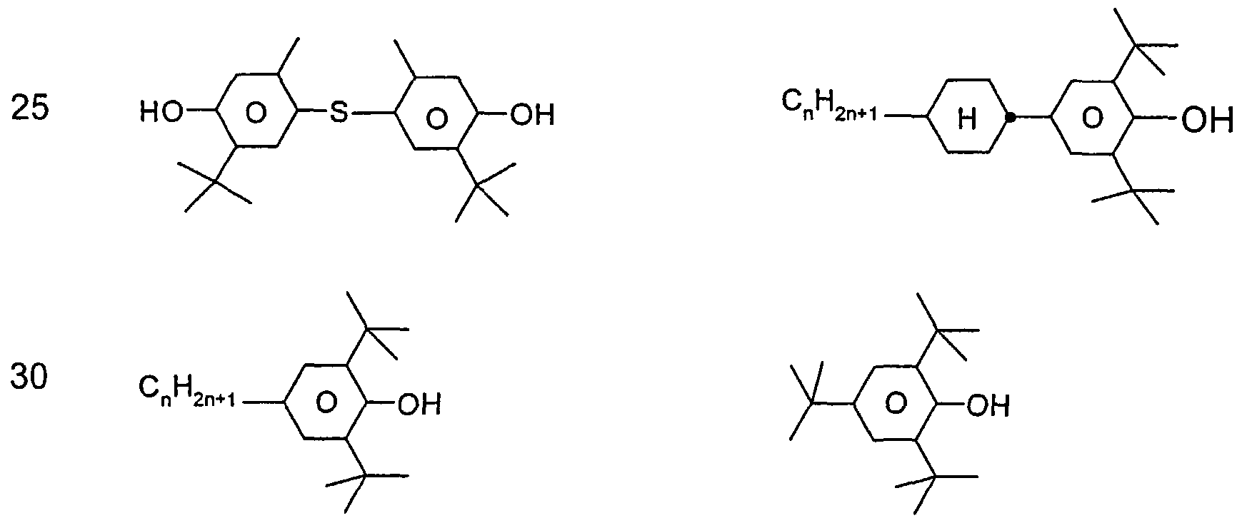
- Stabilizers which can be added, for example, to the mixtures according to the invention in amounts of 0-10% by weight are mentioned below.
Landscapes
- Chemical & Material Sciences (AREA)
- Crystallography & Structural Chemistry (AREA)
- Engineering & Computer Science (AREA)
- Materials Engineering (AREA)
- Organic Chemistry (AREA)
- Liquid Crystal Substances (AREA)
- Steroid Compounds (AREA)
Abstract
Description


Claims


Priority Applications (5)
| Application Number | Priority Date | Filing Date | Title |
|---|---|---|---|
| JP2007515868A JP4932705B2 (ja) | 2004-06-18 | 2005-06-15 | 液晶媒体 |
| US11/629,626 US7635505B2 (en) | 2004-06-18 | 2005-06-15 | Liquid Crystalline Medium |
| KR1020067026548A KR101140503B1 (ko) | 2004-06-18 | 2005-06-15 | 액정 매질 |
| DE502005006151T DE502005006151D1 (de) | 2004-06-18 | 2005-06-15 | Flüssigkristallines medium |
| EP05755107A EP1756247B1 (de) | 2004-06-18 | 2005-06-15 | Flüssigkristallines medium |
Applications Claiming Priority (2)
| Application Number | Priority Date | Filing Date | Title |
|---|---|---|---|
| DE102004029602 | 2004-06-18 | ||
| DE102004029602.2 | 2004-06-18 |
Publications (1)
| Publication Number | Publication Date |
|---|---|
| WO2005123879A1 true WO2005123879A1 (de) | 2005-12-29 |
Family
ID=34971200
Family Applications (1)
| Application Number | Title | Priority Date | Filing Date |
|---|---|---|---|
| PCT/EP2005/006428 WO2005123879A1 (de) | 2004-06-18 | 2005-06-15 | Flüssigkristallines medium |
Country Status (8)
| Country | Link |
|---|---|
| US (1) | US7635505B2 (de) |
| EP (1) | EP1756247B1 (de) |
| JP (1) | JP4932705B2 (de) |
| KR (1) | KR101140503B1 (de) |
| AT (1) | ATE416242T1 (de) |
| DE (1) | DE502005006151D1 (de) |
| TW (1) | TWI381038B (de) |
| WO (1) | WO2005123879A1 (de) |
Cited By (22)
| Publication number | Priority date | Publication date | Assignee | Title |
|---|---|---|---|---|
| EP1726633A1 (de) * | 2005-05-25 | 2006-11-29 | MERCK PATENT GmbH | Flüssigkristallines Medium und Flüssigkristallanzeige |
| WO2007079949A1 (de) * | 2006-01-10 | 2007-07-19 | Merck Patent Gmbh | Flüssigkristallines medium |
| EP1835010A1 (de) | 2006-03-17 | 2007-09-19 | Merck Patent GmbH | Flüssigkristallines Medium und Flüssigkristallanzeige |
| JP2007246906A (ja) * | 2006-03-17 | 2007-09-27 | Merck Patent Gmbh | 液晶媒体および液晶ディスプレイ |
| WO2007118623A1 (de) * | 2006-04-13 | 2007-10-25 | Merck Patent Gmbh | Flüssigkristallines medium |
| EP1908813A1 (de) * | 2006-10-04 | 2008-04-09 | Merck Patent GmbH | Flüssigkristallines Medium |
| EP1908811A1 (de) | 2006-10-04 | 2008-04-09 | Merck Patent GmbH | Flüssigkristallines Medium |
| EP1935960A1 (de) * | 2006-12-20 | 2008-06-25 | Merck Patent GmbH | Flüssigkristallines Medium und Flüssigkristallanzeige |
| JP2008156621A (ja) * | 2006-11-28 | 2008-07-10 | Merck Patent Gmbh | 液晶媒体 |
| WO2009115226A1 (en) * | 2008-03-19 | 2009-09-24 | Merck Patent Gmbh | Liquid crystalline medium and liquid crystal display |
| WO2009156118A1 (en) * | 2008-06-27 | 2009-12-30 | Merck Patent Gmbh | Liquid-crystalline medium |
| EP2189511A2 (de) | 2006-09-01 | 2010-05-26 | Merck Patent GmbH | Flüssigkristallines Medium |
| JP2010526771A (ja) * | 2007-04-24 | 2010-08-05 | メルク パテント ゲゼルシャフト ミット ベシュレンクテル ハフツング | 液晶混合物のためのピリジン化合物 |
| WO2011009524A1 (de) * | 2009-07-21 | 2011-01-27 | Merck Patent Gmbh | Flüssigkristallines medium und dieses enthaltende hochfrequenzbauteile |
| US8236390B2 (en) * | 2007-12-21 | 2012-08-07 | MERCK Patent Gesellschaft mit beschränkter Haftung | Liquid-crystalline medium |
| EP2801602A4 (de) * | 2012-11-28 | 2015-11-11 | Dainippon Ink & Chemicals | Nematische flüssigkristallzusammensetzung und flüssigkristallanzeigeelement damit |
| CN105295954A (zh) * | 2008-01-14 | 2016-02-03 | 默克专利股份有限公司 | 液晶介质 |
| EP2806011A4 (de) * | 2013-03-05 | 2016-02-17 | Dainippon Ink & Chemicals | Flüssigkristallzusammensetzung und flüssigkristallanzeigeelement damit |
| JP2016102222A (ja) * | 2016-02-24 | 2016-06-02 | Dic株式会社 | ネマチック液晶組成物 |
| EP2714843B1 (de) | 2011-06-01 | 2016-12-21 | Merck Patent GmbH | Flüssigkristallines medium und flüssigkristallanzeigevorrichtung |
| US9695361B2 (en) | 2012-10-05 | 2017-07-04 | Dic Corporation | Liquid crystal composition and liquid crystal display element using the same |
| JP2018035371A (ja) * | 2017-11-13 | 2018-03-08 | Dic株式会社 | ネマチック液晶組成物 |
Families Citing this family (35)
| Publication number | Priority date | Publication date | Assignee | Title |
|---|---|---|---|---|
| ATE517967T1 (de) * | 2004-06-18 | 2011-08-15 | Merck Patent Gmbh | Flüssigkristallines medium |
| ATE417910T1 (de) * | 2005-05-25 | 2009-01-15 | Merck Patent Gmbh | Flüssigkristallines medium und flüssigkristallanzeige |
| JP5405034B2 (ja) * | 2007-03-26 | 2014-02-05 | メルク パテント ゲゼルシャフト ミット ベシュレンクテル ハフツング | 液晶媒体および液晶ディスプレイ |
| US7582338B2 (en) * | 2007-04-13 | 2009-09-01 | Merck Patent Gesellschaft Mit Beschrankter Haftung | Liquid crystal medium |
| KR101647510B1 (ko) * | 2007-11-28 | 2016-08-10 | 메르크 파텐트 게엠베하 | 액정 매질 및 액정 디스플레이 |
| KR20110046481A (ko) * | 2008-08-28 | 2011-05-04 | 짓쏘 가부시끼가이샤 | 액정 조성물 및 액정 표시 소자 |
| DE102010006691A1 (de) | 2009-02-06 | 2010-10-28 | Merck Patent Gmbh | Flüssigkristallines Medium und Flüssigkristallanzeige |
| TWI509055B (zh) | 2009-05-14 | 2015-11-21 | Jnc Corp | 液晶組成物及液晶顯示元件 |
| EP2292720A1 (de) | 2009-09-08 | 2011-03-09 | Merck Patent GmbH | Flüssigkristallanzeige |
| WO2011030708A1 (ja) * | 2009-09-14 | 2011-03-17 | チッソ株式会社 | 液晶組成物および液晶表示素子 |
| DE102010052795A1 (de) * | 2009-12-21 | 2011-06-22 | Merck Patent GmbH, 64293 | Flüssigkristallines Medium und Flüssigkristallanzeige |
| WO2011098214A1 (de) * | 2010-02-15 | 2011-08-18 | Merck Patent Gmbh | Flüssigkristallines medium |
| US8968595B2 (en) * | 2011-09-02 | 2015-03-03 | Industrial Technology Research Institute | Methods for recycling liquid crystal and forming reformulated liquid crystal mixtures |
| DE102012024126A1 (de) * | 2011-12-20 | 2013-06-20 | Merck Patent Gmbh | Flüssigkristallines Medium |
| CN102732260B (zh) * | 2012-04-26 | 2014-01-15 | 北京八亿时空液晶科技股份有限公司 | 一种超扭曲向列型液晶组合物 |
| KR101370950B1 (ko) * | 2012-07-18 | 2014-03-10 | 디아이씨 가부시끼가이샤 | 네마틱 액정 조성물 및 이를 사용한 액정 표시 소자 |
| JP5282989B1 (ja) * | 2012-07-18 | 2013-09-04 | Dic株式会社 | ネマチック液晶組成物及びこれを用いた液晶表示素子 |
| JP5622057B2 (ja) * | 2012-09-27 | 2014-11-12 | Dic株式会社 | ネマチック液晶組成物 |
| JP5622056B2 (ja) * | 2012-09-27 | 2014-11-12 | Dic株式会社 | ネマチック液晶組成物 |
| JP5622058B2 (ja) * | 2012-09-27 | 2014-11-12 | Dic株式会社 | ネマチック液晶組成物 |
| TW201432032A (zh) * | 2012-11-09 | 2014-08-16 | Dainippon Ink & Chemicals | 液晶組成物及使用此之液晶顯示元件 |
| WO2014102960A1 (ja) * | 2012-12-27 | 2014-07-03 | Dic株式会社 | フルオロビフェニル含有組成物 |
| JP5534110B1 (ja) * | 2012-12-27 | 2014-06-25 | Dic株式会社 | フルオロビフェニル含有組成物 |
| KR20150123146A (ko) | 2013-02-20 | 2015-11-03 | 디아이씨 가부시끼가이샤 | 액정 조성물, 액정 표시 소자 및 액정 디스플레이 |
| WO2014136216A1 (ja) * | 2013-03-06 | 2014-09-12 | Dic株式会社 | 液晶組成物及びこれを用いた液晶表示素子 |
| CN104812870B (zh) * | 2013-03-22 | 2016-07-13 | Dic株式会社 | 液晶组合物和使用该液晶组合物的液晶显示元件 |
| CN103320145B (zh) * | 2013-06-28 | 2015-01-07 | 石家庄诚志永华显示材料有限公司 | 含有二氟亚甲基醚的快速响应液晶组合物 |
| CN103484130B (zh) * | 2013-09-25 | 2015-05-20 | 石家庄诚志永华显示材料有限公司 | 含环丁烷基化合物的液晶组合物 |
| CN103468271B (zh) * | 2013-09-25 | 2015-05-20 | 石家庄诚志永华显示材料有限公司 | 一种正介电各向异性液晶组合物 |
| JP5817890B2 (ja) * | 2014-06-19 | 2015-11-18 | Dic株式会社 | ネマチック液晶組成物 |
| JP6123750B2 (ja) * | 2014-07-23 | 2017-05-10 | Dic株式会社 | 液晶組成物及びそれを使用した液晶表示素子 |
| JP6083424B2 (ja) * | 2014-10-03 | 2017-02-22 | Dic株式会社 | ネマチック液晶組成物 |
| CN104610984B (zh) * | 2014-12-31 | 2017-01-25 | 石家庄诚志永华显示材料有限公司 | 液晶组合物 |
| KR20160098586A (ko) * | 2015-02-09 | 2016-08-19 | 삼성디스플레이 주식회사 | 액정 조성물, 이를 포함하는 액정 표시 장치 및 그 제조 방법 |
| CN105331369B (zh) * | 2015-11-12 | 2018-06-12 | 石家庄诚志永华显示材料有限公司 | 含有2,4-二氟苯基团化合物的液晶介质及应用 |
Citations (12)
| Publication number | Priority date | Publication date | Assignee | Title |
|---|---|---|---|---|
| US4676604A (en) | 1983-03-16 | 1987-06-30 | Hoffmann-La Roche Inc. | Liquid crystals |
| WO1989002884A1 (en) | 1987-09-25 | 1989-04-06 | MERCK Patent Gesellschaft mit beschränkter Haftung | Substituted phenyltrifluormethylethers |
| WO1990001056A1 (de) | 1988-07-27 | 1990-02-08 | MERCK Patent Gesellschaft mit beschränkter Haftung | Difluormethylverbindungen |
| DE4006921A1 (de) | 1989-03-18 | 1990-09-20 | Merck Patent Gmbh | Difluormethylenverbindungen |
| WO1991003450A1 (de) | 1989-09-06 | 1991-03-21 | MERCK Patent Gesellschaft mit beschränkter Haftung | Fluorbenzolderivate und flüssigkristallines medium |
| EP0439089B1 (de) | 1990-01-25 | 1995-07-12 | MERCK PATENT GmbH | Halogenierte Terphenyle und flüssigkristallines Medium |
| DE4445224A1 (de) | 1994-12-17 | 1996-06-20 | Merck Patent Gmbh | Benzolderivate |
| WO1998023564A1 (fr) | 1996-11-28 | 1998-06-04 | Chisso Corporation | Derives de benzene a substitution de fluor, composition a cristaux liquides et element d'affichage a cristaux liquides |
| EP1302523A1 (de) | 2001-10-12 | 2003-04-16 | MERCK PATENT GmbH | Flüssigkristallines Medium |
| US6565933B2 (en) | 1998-04-30 | 2003-05-20 | Merck Patent Gmbh | Liquid-crystalline medium |
| EP1346995A1 (de) | 2002-03-15 | 2003-09-24 | MERCK PATENT GmbH | Verfahren zur Herstellung von Ringverbindungen |
| WO2004035710A1 (de) | 2002-10-15 | 2004-04-29 | Merck Patent Gmbh | Photostabiles flüssigkristallines medium |
Family Cites Families (4)
| Publication number | Priority date | Publication date | Assignee | Title |
|---|---|---|---|---|
| JPH04234339A (ja) * | 1990-07-20 | 1992-08-24 | Merck Patent Gmbh | トリフルオロメチル化合物類 |
| EP1310474B1 (de) * | 2001-11-09 | 2007-01-03 | MERCK PATENT GmbH | Fluorierte Biphenylverbindungen und ihre Verwendung in flüssigkristallinen Medien |
| JP4206687B2 (ja) * | 2002-04-09 | 2009-01-14 | チッソ株式会社 | 液晶組成物および液晶表示素子 |
| JP4964765B2 (ja) * | 2004-06-18 | 2012-07-04 | メルク パテント ゲゼルシャフト ミット ベシュレンクテル ハフツング | 液晶媒体 |
-
2005
- 2005-06-15 DE DE502005006151T patent/DE502005006151D1/de active Active
- 2005-06-15 EP EP05755107A patent/EP1756247B1/de active Active
- 2005-06-15 AT AT05755107T patent/ATE416242T1/de not_active IP Right Cessation
- 2005-06-15 KR KR1020067026548A patent/KR101140503B1/ko active IP Right Grant
- 2005-06-15 JP JP2007515868A patent/JP4932705B2/ja active Active
- 2005-06-15 WO PCT/EP2005/006428 patent/WO2005123879A1/de active Application Filing
- 2005-06-15 US US11/629,626 patent/US7635505B2/en active Active
- 2005-06-17 TW TW094120355A patent/TWI381038B/zh active
Patent Citations (16)
| Publication number | Priority date | Publication date | Assignee | Title |
|---|---|---|---|---|
| US4676604A (en) | 1983-03-16 | 1987-06-30 | Hoffmann-La Roche Inc. | Liquid crystals |
| WO1989002884A1 (en) | 1987-09-25 | 1989-04-06 | MERCK Patent Gesellschaft mit beschränkter Haftung | Substituted phenyltrifluormethylethers |
| EP0334911A1 (de) | 1987-09-25 | 1989-10-04 | MERCK PATENT GmbH | Substituierte phenyltrifluormethylether |
| EP0334911B1 (de) * | 1987-09-25 | 1993-02-10 | MERCK PATENT GmbH | Substituierte phenyltrifluormethylether |
| WO1990001056A1 (de) | 1988-07-27 | 1990-02-08 | MERCK Patent Gesellschaft mit beschränkter Haftung | Difluormethylverbindungen |
| DE4006921A1 (de) | 1989-03-18 | 1990-09-20 | Merck Patent Gmbh | Difluormethylenverbindungen |
| WO1991003450A1 (de) | 1989-09-06 | 1991-03-21 | MERCK Patent Gesellschaft mit beschränkter Haftung | Fluorbenzolderivate und flüssigkristallines medium |
| EP0439089B1 (de) | 1990-01-25 | 1995-07-12 | MERCK PATENT GmbH | Halogenierte Terphenyle und flüssigkristallines Medium |
| DE4445224A1 (de) | 1994-12-17 | 1996-06-20 | Merck Patent Gmbh | Benzolderivate |
| WO1998023564A1 (fr) | 1996-11-28 | 1998-06-04 | Chisso Corporation | Derives de benzene a substitution de fluor, composition a cristaux liquides et element d'affichage a cristaux liquides |
| US6565933B2 (en) | 1998-04-30 | 2003-05-20 | Merck Patent Gmbh | Liquid-crystalline medium |
| US6596350B2 (en) | 1998-04-30 | 2003-07-22 | Merck Patent Gesellschaft Mit Beschrankter Haftung | Liquid-crystalline medium |
| US6669998B2 (en) | 1998-04-30 | 2003-12-30 | Merck Patent Gesellschaft | Liquid-crystalline medium |
| EP1302523A1 (de) | 2001-10-12 | 2003-04-16 | MERCK PATENT GmbH | Flüssigkristallines Medium |
| EP1346995A1 (de) | 2002-03-15 | 2003-09-24 | MERCK PATENT GmbH | Verfahren zur Herstellung von Ringverbindungen |
| WO2004035710A1 (de) | 2002-10-15 | 2004-04-29 | Merck Patent Gmbh | Photostabiles flüssigkristallines medium |
Cited By (36)
| Publication number | Priority date | Publication date | Assignee | Title |
|---|---|---|---|---|
| EP1726633A1 (de) * | 2005-05-25 | 2006-11-29 | MERCK PATENT GmbH | Flüssigkristallines Medium und Flüssigkristallanzeige |
| WO2007079949A1 (de) * | 2006-01-10 | 2007-07-19 | Merck Patent Gmbh | Flüssigkristallines medium |
| US7563491B2 (en) | 2006-03-17 | 2009-07-21 | Merck Patent Gmbh | Liquid crystalline medium and liquid crystal display |
| EP1835010A1 (de) | 2006-03-17 | 2007-09-19 | Merck Patent GmbH | Flüssigkristallines Medium und Flüssigkristallanzeige |
| JP2007246906A (ja) * | 2006-03-17 | 2007-09-27 | Merck Patent Gmbh | 液晶媒体および液晶ディスプレイ |
| US7740918B2 (en) | 2006-03-17 | 2010-06-22 | Merck Patent Gmbh | Liquid crystalline medium and liquid crystal display |
| WO2007118623A1 (de) * | 2006-04-13 | 2007-10-25 | Merck Patent Gmbh | Flüssigkristallines medium |
| EP2189511A2 (de) | 2006-09-01 | 2010-05-26 | Merck Patent GmbH | Flüssigkristallines Medium |
| EP2189511A3 (de) * | 2006-09-01 | 2010-07-14 | Merck Patent GmbH | Flüssigkristallines Medium |
| KR101497147B1 (ko) | 2006-10-04 | 2015-02-27 | 메르크 파텐트 게엠베하 | 액정 매질 |
| EP1908811A1 (de) | 2006-10-04 | 2008-04-09 | Merck Patent GmbH | Flüssigkristallines Medium |
| EP2248872A3 (de) * | 2006-10-04 | 2011-10-12 | Merck Patent GmbH | Flüssigkristallines Medium |
| EP1908813A1 (de) * | 2006-10-04 | 2008-04-09 | Merck Patent GmbH | Flüssigkristallines Medium |
| JP2008156621A (ja) * | 2006-11-28 | 2008-07-10 | Merck Patent Gmbh | 液晶媒体 |
| EP1935960A1 (de) * | 2006-12-20 | 2008-06-25 | Merck Patent GmbH | Flüssigkristallines Medium und Flüssigkristallanzeige |
| JP2010526771A (ja) * | 2007-04-24 | 2010-08-05 | メルク パテント ゲゼルシャフト ミット ベシュレンクテル ハフツング | 液晶混合物のためのピリジン化合物 |
| US8236390B2 (en) * | 2007-12-21 | 2012-08-07 | MERCK Patent Gesellschaft mit beschränkter Haftung | Liquid-crystalline medium |
| CN105295954A (zh) * | 2008-01-14 | 2016-02-03 | 默克专利股份有限公司 | 液晶介质 |
| WO2009115226A1 (en) * | 2008-03-19 | 2009-09-24 | Merck Patent Gmbh | Liquid crystalline medium and liquid crystal display |
| US8262930B2 (en) | 2008-03-19 | 2012-09-11 | Merck Patent Gesellschaft Mit Beschrankter Haftung | Liquid crystalline medium and liquid crystal display |
| US8974693B2 (en) | 2008-06-27 | 2015-03-10 | Merck Patent Gmbh | Liquid-crystalline medium |
| WO2009156118A1 (en) * | 2008-06-27 | 2009-12-30 | Merck Patent Gmbh | Liquid-crystalline medium |
| US8956549B2 (en) | 2008-06-27 | 2015-02-17 | Merck Patent Gmbh | Liquid-crystalline medium |
| US8956550B2 (en) | 2008-06-27 | 2015-02-17 | Merck Patent Gmbh | Liquid-crystalline medium |
| US8551358B2 (en) | 2008-06-27 | 2013-10-08 | Merck Patent Gmbh | Liquid-crystalline medium |
| EP2692827A3 (de) * | 2008-06-27 | 2014-04-23 | Merck Patent GmbH | Flüssigkristallines Medium |
| WO2011009524A1 (de) * | 2009-07-21 | 2011-01-27 | Merck Patent Gmbh | Flüssigkristallines medium und dieses enthaltende hochfrequenzbauteile |
| US9657231B2 (en) | 2009-07-21 | 2017-05-23 | Merck Patent Gmbh | Liquid crystal medium and high-frequency components containing the same |
| EP2714843B1 (de) | 2011-06-01 | 2016-12-21 | Merck Patent GmbH | Flüssigkristallines medium und flüssigkristallanzeigevorrichtung |
| US10450509B2 (en) | 2011-06-01 | 2019-10-22 | Merck Patent Gmbh | Liquid crystal medium and liquid display |
| EP2714843B2 (de) † | 2011-06-01 | 2019-10-30 | Merck Patent GmbH | Flüssigkristallines medium und flüssigkristallanzeigevorrichtung |
| US9695361B2 (en) | 2012-10-05 | 2017-07-04 | Dic Corporation | Liquid crystal composition and liquid crystal display element using the same |
| EP2801602A4 (de) * | 2012-11-28 | 2015-11-11 | Dainippon Ink & Chemicals | Nematische flüssigkristallzusammensetzung und flüssigkristallanzeigeelement damit |
| EP2806011A4 (de) * | 2013-03-05 | 2016-02-17 | Dainippon Ink & Chemicals | Flüssigkristallzusammensetzung und flüssigkristallanzeigeelement damit |
| JP2016102222A (ja) * | 2016-02-24 | 2016-06-02 | Dic株式会社 | ネマチック液晶組成物 |
| JP2018035371A (ja) * | 2017-11-13 | 2018-03-08 | Dic株式会社 | ネマチック液晶組成物 |
Also Published As
| Publication number | Publication date |
|---|---|
| EP1756247B1 (de) | 2008-12-03 |
| KR101140503B1 (ko) | 2012-04-30 |
| TWI381038B (zh) | 2013-01-01 |
| KR20070029202A (ko) | 2007-03-13 |
| JP2008502754A (ja) | 2008-01-31 |
| JP4932705B2 (ja) | 2012-05-16 |
| ATE416242T1 (de) | 2008-12-15 |
| US20080128653A1 (en) | 2008-06-05 |
| TW200613525A (en) | 2006-05-01 |
| EP1756247A1 (de) | 2007-02-28 |
| DE502005006151D1 (de) | 2009-01-15 |
| US7635505B2 (en) | 2009-12-22 |
Similar Documents
| Publication | Publication Date | Title |
|---|---|---|
| EP1756247B1 (de) | Flüssigkristallines medium | |
| DE102004030315B4 (de) | Flüssigkristallines Medium und seine Verwendung | |
| EP2182041B1 (de) | Flüssigkristallines Medium enthaltend 1,2-Difluorethenverbindungen, sowie Flüssigkristallanzeige | |
| EP1551937B1 (de) | Photostabiles flüssigkristallines medium | |
| EP1454975B1 (de) | Flüssigkristallines Medium | |
| EP1956069B1 (de) | Flüssigkristallines Medium | |
| EP2229427B1 (de) | Flüssigkristallines medium | |
| EP1658353B1 (de) | Flüssigkristallines medium | |
| EP1758966B1 (de) | Flüssigkristallines medium | |
| WO2001046336A2 (de) | Flüssigkristallines medium | |
| EP1756248B1 (de) | Flüssigkristallines medium | |
| EP2057251A1 (de) | Flüssigkristallines medium | |
| DE19859421A1 (de) | Flüssigkristallines Medium | |
| EP1335014B1 (de) | Flüssigkristallines Medium | |
| DE10344474B4 (de) | Flüssigkristallines Medium und seine Verwendung | |
| DE102005027762A1 (de) | Flüssigkristallines Medium | |
| EP1629064A1 (de) | Flüssigkristallines medium | |
| DE10002462B4 (de) | Flüssigkristallines Medium und seine Verwendung | |
| EP1199346A2 (de) | Flüssigkristallines Medium | |
| DE102006006116B4 (de) | Flüssigkristallines Medium und seine Verwendung | |
| EP1971667A1 (de) | Flüssigkristallines medium |
Legal Events
| Date | Code | Title | Description |
|---|---|---|---|
| AK | Designated states |
Kind code of ref document: A1 Designated state(s): AE AG AL AM AT AU AZ BA BB BG BR BW BY BZ CA CH CN CO CR CU CZ DE DK DM DZ EC EE EG ES FI GB GD GE GH GM HR HU ID IL IN IS JP KE KG KM KP KR KZ LC LK LR LS LT LU LV MA MD MG MK MN MW MX MZ NA NG NI NO NZ OM PG PH PL PT RO RU SC SD SE SG SK SL SM SY TJ TM TN TR TT TZ UA UG US UZ VC VN YU ZA ZM ZW |
|
| AL | Designated countries for regional patents |
Kind code of ref document: A1 Designated state(s): BW GH GM KE LS MW MZ NA SD SL SZ TZ UG ZM ZW AM AZ BY KG KZ MD RU TJ TM AT BE BG CH CY CZ DE DK EE ES FI FR GB GR HU IE IS IT LT LU MC NL PL PT RO SE SI SK TR BF BJ CF CG CI CM GA GN GQ GW ML MR NE SN TD TG |
|
| 121 | Ep: the epo has been informed by wipo that ep was designated in this application | ||
| WWE | Wipo information: entry into national phase |
Ref document number: 2005755107 Country of ref document: EP |
|
| WWE | Wipo information: entry into national phase |
Ref document number: 1020067026548 Country of ref document: KR |
|
| WWE | Wipo information: entry into national phase |
Ref document number: 2007515868 Country of ref document: JP |
|
| NENP | Non-entry into the national phase |
Ref country code: DE |
|
| WWW | Wipo information: withdrawn in national office |
Country of ref document: DE |
|
| WWP | Wipo information: published in national office |
Ref document number: 2005755107 Country of ref document: EP |
|
| WWP | Wipo information: published in national office |
Ref document number: 1020067026548 Country of ref document: KR |
|
| WWE | Wipo information: entry into national phase |
Ref document number: 11629626 Country of ref document: US |
|
| WWP | Wipo information: published in national office |
Ref document number: 11629626 Country of ref document: US |