WO2004096432A1 - Active antiseptic water or active antiseptic water system fluid, and method and device for production the same - Google Patents
Active antiseptic water or active antiseptic water system fluid, and method and device for production the same Download PDFInfo
- Publication number
- WO2004096432A1 WO2004096432A1 PCT/JP2004/005324 JP2004005324W WO2004096432A1 WO 2004096432 A1 WO2004096432 A1 WO 2004096432A1 JP 2004005324 W JP2004005324 W JP 2004005324W WO 2004096432 A1 WO2004096432 A1 WO 2004096432A1
- Authority
- WO
- WIPO (PCT)
- Prior art keywords
- vibration
- water
- photocatalyst
- vibrating
- blade
- Prior art date
Links
- XLYOFNOQVPJJNP-UHFFFAOYSA-N water Substances O XLYOFNOQVPJJNP-UHFFFAOYSA-N 0.000 title claims abstract description 296
- 238000000034 method Methods 0.000 title claims abstract description 47
- 230000002421 anti-septic effect Effects 0.000 title claims description 91
- 239000012530 fluid Substances 0.000 title claims description 89
- 238000004519 manufacturing process Methods 0.000 title claims description 31
- 238000012545 processing Methods 0.000 claims abstract description 128
- 229910052751 metal Inorganic materials 0.000 claims abstract description 103
- 239000002184 metal Substances 0.000 claims abstract description 103
- 238000003756 stirring Methods 0.000 claims abstract description 71
- 239000007788 liquid Substances 0.000 claims abstract description 45
- 230000001678 irradiating effect Effects 0.000 claims abstract description 29
- 230000003287 optical effect Effects 0.000 claims abstract 5
- 239000011941 photocatalyst Substances 0.000 claims description 196
- 229910052736 halogen Inorganic materials 0.000 claims description 55
- 150000002367 halogens Chemical class 0.000 claims description 53
- 230000002070 germicidal effect Effects 0.000 claims description 49
- 230000001954 sterilising effect Effects 0.000 claims description 30
- 230000000694 effects Effects 0.000 claims description 29
- IJGRMHOSHXDMSA-UHFFFAOYSA-N Atomic nitrogen Chemical compound N#N IJGRMHOSHXDMSA-UHFFFAOYSA-N 0.000 claims description 28
- 239000003755 preservative agent Substances 0.000 claims description 28
- 230000002335 preservative effect Effects 0.000 claims description 27
- 229910052801 chlorine Inorganic materials 0.000 claims description 24
- 239000000460 chlorine Substances 0.000 claims description 24
- 239000000463 material Substances 0.000 claims description 23
- ZAMOUSCENKQFHK-UHFFFAOYSA-N Chlorine atom Chemical compound [Cl] ZAMOUSCENKQFHK-UHFFFAOYSA-N 0.000 claims description 22
- IOVCWXUNBOPUCH-UHFFFAOYSA-M Nitrite anion Chemical compound [O-]N=O IOVCWXUNBOPUCH-UHFFFAOYSA-M 0.000 claims description 19
- 239000013307 optical fiber Substances 0.000 claims description 18
- NINIDFKCEFEMDL-UHFFFAOYSA-N Sulfur Chemical compound [S] NINIDFKCEFEMDL-UHFFFAOYSA-N 0.000 claims description 17
- 229910052717 sulfur Inorganic materials 0.000 claims description 17
- 239000011593 sulfur Substances 0.000 claims description 17
- 230000000844 anti-bacterial effect Effects 0.000 claims description 16
- -1 nitrite ions Chemical class 0.000 claims description 16
- 230000005291 magnetic effect Effects 0.000 claims description 15
- 229940005654 nitrite ion Drugs 0.000 claims description 15
- LSNNMFCWUKXFEE-UHFFFAOYSA-M Bisulfite Chemical compound OS([O-])=O LSNNMFCWUKXFEE-UHFFFAOYSA-M 0.000 claims description 14
- 229910052757 nitrogen Inorganic materials 0.000 claims description 14
- 230000002829 reductive effect Effects 0.000 claims description 9
- 239000000126 substance Substances 0.000 claims description 8
- 238000009413 insulation Methods 0.000 claims description 7
- LSNNMFCWUKXFEE-UHFFFAOYSA-L sulfite Chemical compound [O-]S([O-])=O LSNNMFCWUKXFEE-UHFFFAOYSA-L 0.000 claims description 6
- 238000013019 agitation Methods 0.000 claims description 5
- 235000011389 fruit/vegetable juice Nutrition 0.000 claims description 5
- LSNNMFCWUKXFEE-UHFFFAOYSA-N Sulfurous acid Chemical compound OS(O)=O LSNNMFCWUKXFEE-UHFFFAOYSA-N 0.000 claims description 4
- 235000014101 wine Nutrition 0.000 claims description 4
- 239000011810 insulating material Substances 0.000 claims description 3
- 238000004321 preservation Methods 0.000 claims description 3
- 230000009467 reduction Effects 0.000 claims description 3
- 239000002357 osmotic agent Substances 0.000 claims description 2
- 238000000354 decomposition reaction Methods 0.000 claims 2
- 238000010276 construction Methods 0.000 claims 1
- 239000012774 insulation material Substances 0.000 claims 1
- 239000003054 catalyst Substances 0.000 abstract 4
- 239000000645 desinfectant Substances 0.000 abstract 2
- 239000010410 layer Substances 0.000 description 93
- 239000010936 titanium Substances 0.000 description 25
- RTAQQCXQSZGOHL-UHFFFAOYSA-N Titanium Chemical compound [Ti] RTAQQCXQSZGOHL-UHFFFAOYSA-N 0.000 description 24
- 229910052719 titanium Inorganic materials 0.000 description 24
- GWEVSGVZZGPLCZ-UHFFFAOYSA-N Titan oxide Chemical compound O=[Ti]=O GWEVSGVZZGPLCZ-UHFFFAOYSA-N 0.000 description 21
- 239000000696 magnetic material Substances 0.000 description 21
- OGIDPMRJRNCKJF-UHFFFAOYSA-N titanium oxide Inorganic materials [Ti]=O OGIDPMRJRNCKJF-UHFFFAOYSA-N 0.000 description 16
- 239000008399 tap water Substances 0.000 description 14
- 235000020679 tap water Nutrition 0.000 description 14
- 239000000057 synthetic resin Substances 0.000 description 13
- 229920003002 synthetic resin Polymers 0.000 description 13
- 238000007747 plating Methods 0.000 description 12
- 239000002344 surface layer Substances 0.000 description 12
- 239000002245 particle Substances 0.000 description 11
- 235000010724 Wisteria floribunda Nutrition 0.000 description 9
- 150000002013 dioxins Chemical class 0.000 description 8
- 229920001971 elastomer Polymers 0.000 description 8
- QSHDDOUJBYECFT-UHFFFAOYSA-N mercury Chemical compound [Hg] QSHDDOUJBYECFT-UHFFFAOYSA-N 0.000 description 8
- 229910052753 mercury Inorganic materials 0.000 description 8
- 241000894006 Bacteria Species 0.000 description 7
- 235000013361 beverage Nutrition 0.000 description 7
- 238000010586 diagram Methods 0.000 description 7
- 230000007246 mechanism Effects 0.000 description 7
- 239000000243 solution Substances 0.000 description 7
- 238000001228 spectrum Methods 0.000 description 7
- XEEYBQQBJWHFJM-UHFFFAOYSA-N Iron Chemical compound [Fe] XEEYBQQBJWHFJM-UHFFFAOYSA-N 0.000 description 6
- 230000005540 biological transmission Effects 0.000 description 6
- 235000020188 drinking water Nutrition 0.000 description 6
- 239000003651 drinking water Substances 0.000 description 6
- 235000013305 food Nutrition 0.000 description 6
- 239000010935 stainless steel Substances 0.000 description 6
- 229910001220 stainless steel Inorganic materials 0.000 description 6
- 238000004659 sterilization and disinfection Methods 0.000 description 6
- 241000227653 Lycopersicon Species 0.000 description 5
- 235000007688 Lycopersicon esculentum Nutrition 0.000 description 5
- NHNBFGGVMKEFGY-UHFFFAOYSA-N Nitrate Chemical compound [O-][N+]([O-])=O NHNBFGGVMKEFGY-UHFFFAOYSA-N 0.000 description 5
- VYPSYNLAJGMNEJ-UHFFFAOYSA-N Silicium dioxide Chemical compound O=[Si]=O VYPSYNLAJGMNEJ-UHFFFAOYSA-N 0.000 description 5
- 244000269722 Thea sinensis Species 0.000 description 5
- MMDJDBSEMBIJBB-UHFFFAOYSA-N [O-][N+]([O-])=O.[O-][N+]([O-])=O.[O-][N+]([O-])=O.[NH6+3] Chemical compound [O-][N+]([O-])=O.[O-][N+]([O-])=O.[O-][N+]([O-])=O.[NH6+3] MMDJDBSEMBIJBB-UHFFFAOYSA-N 0.000 description 5
- 229910045601 alloy Inorganic materials 0.000 description 5
- 239000000956 alloy Substances 0.000 description 5
- 238000000855 fermentation Methods 0.000 description 5
- 230000004151 fermentation Effects 0.000 description 5
- 150000002739 metals Chemical class 0.000 description 5
- 150000002896 organic halogen compounds Chemical class 0.000 description 5
- 239000004033 plastic Substances 0.000 description 5
- 229920003023 plastic Polymers 0.000 description 5
- BASFCYQUMIYNBI-UHFFFAOYSA-N platinum Substances [Pt] BASFCYQUMIYNBI-UHFFFAOYSA-N 0.000 description 5
- 239000000047 product Substances 0.000 description 5
- 239000002994 raw material Substances 0.000 description 5
- 235000013616 tea Nutrition 0.000 description 5
- 239000004278 EU approved seasoning Substances 0.000 description 4
- QAOWNCQODCNURD-UHFFFAOYSA-L Sulfate Chemical compound [O-]S([O-])(=O)=O QAOWNCQODCNURD-UHFFFAOYSA-L 0.000 description 4
- 239000004809 Teflon Substances 0.000 description 4
- 229920006362 Teflon® Polymers 0.000 description 4
- XKMRRTOUMJRJIA-UHFFFAOYSA-N ammonia nh3 Chemical compound N.N XKMRRTOUMJRJIA-UHFFFAOYSA-N 0.000 description 4
- 239000002585 base Substances 0.000 description 4
- 238000009395 breeding Methods 0.000 description 4
- 230000001488 breeding effect Effects 0.000 description 4
- 239000002131 composite material Substances 0.000 description 4
- 230000000249 desinfective effect Effects 0.000 description 4
- 238000005868 electrolysis reaction Methods 0.000 description 4
- 235000011194 food seasoning agent Nutrition 0.000 description 4
- 235000019674 grape juice Nutrition 0.000 description 4
- 239000011777 magnesium Substances 0.000 description 4
- 238000005259 measurement Methods 0.000 description 4
- 230000036961 partial effect Effects 0.000 description 4
- 239000010453 quartz Substances 0.000 description 4
- 235000021067 refined food Nutrition 0.000 description 4
- 230000035943 smell Effects 0.000 description 4
- 239000010959 steel Substances 0.000 description 4
- 238000003860 storage Methods 0.000 description 4
- 239000002351 wastewater Substances 0.000 description 4
- 239000002349 well water Substances 0.000 description 4
- 235000020681 well water Nutrition 0.000 description 4
- 229920001817 Agar Polymers 0.000 description 3
- VEXZGXHMUGYJMC-UHFFFAOYSA-M Chloride anion Chemical compound [Cl-] VEXZGXHMUGYJMC-UHFFFAOYSA-M 0.000 description 3
- 240000007154 Coffea arabica Species 0.000 description 3
- 241000196324 Embryophyta Species 0.000 description 3
- 241000282412 Homo Species 0.000 description 3
- 229910002651 NO3 Inorganic materials 0.000 description 3
- JVMRPSJZNHXORP-UHFFFAOYSA-N ON=O.ON=O.ON=O.N Chemical compound ON=O.ON=O.ON=O.N JVMRPSJZNHXORP-UHFFFAOYSA-N 0.000 description 3
- 240000007594 Oryza sativa Species 0.000 description 3
- 235000007164 Oryza sativa Nutrition 0.000 description 3
- HEMHJVSKTPXQMS-UHFFFAOYSA-M Sodium hydroxide Chemical compound [OH-].[Na+] HEMHJVSKTPXQMS-UHFFFAOYSA-M 0.000 description 3
- 229910000831 Steel Inorganic materials 0.000 description 3
- 239000006096 absorbing agent Substances 0.000 description 3
- 230000003213 activating effect Effects 0.000 description 3
- 239000008272 agar Substances 0.000 description 3
- 229910052783 alkali metal Inorganic materials 0.000 description 3
- 235000013527 bean curd Nutrition 0.000 description 3
- 238000004140 cleaning Methods 0.000 description 3
- 235000016213 coffee Nutrition 0.000 description 3
- 235000013353 coffee beverage Nutrition 0.000 description 3
- 238000010411 cooking Methods 0.000 description 3
- 238000001704 evaporation Methods 0.000 description 3
- 230000008020 evaporation Effects 0.000 description 3
- 150000002500 ions Chemical class 0.000 description 3
- 229910052742 iron Inorganic materials 0.000 description 3
- 235000008960 ketchup Nutrition 0.000 description 3
- 229910052749 magnesium Inorganic materials 0.000 description 3
- 235000011837 pasties Nutrition 0.000 description 3
- 230000001699 photocatalysis Effects 0.000 description 3
- 229910052697 platinum Inorganic materials 0.000 description 3
- 229920005989 resin Polymers 0.000 description 3
- 239000011347 resin Substances 0.000 description 3
- 235000009566 rice Nutrition 0.000 description 3
- 239000011734 sodium Substances 0.000 description 3
- 235000013555 soy sauce Nutrition 0.000 description 3
- QGZKDVFQNNGYKY-UHFFFAOYSA-N Ammonia Chemical compound N QGZKDVFQNNGYKY-UHFFFAOYSA-N 0.000 description 2
- OYPRJOBELJOOCE-UHFFFAOYSA-N Calcium Chemical compound [Ca] OYPRJOBELJOOCE-UHFFFAOYSA-N 0.000 description 2
- 241000252229 Carassius auratus Species 0.000 description 2
- CURLTUGMZLYLDI-UHFFFAOYSA-N Carbon dioxide Chemical compound O=C=O CURLTUGMZLYLDI-UHFFFAOYSA-N 0.000 description 2
- RYGMFSIKBFXOCR-UHFFFAOYSA-N Copper Chemical compound [Cu] RYGMFSIKBFXOCR-UHFFFAOYSA-N 0.000 description 2
- VEXZGXHMUGYJMC-UHFFFAOYSA-N Hydrochloric acid Chemical compound Cl VEXZGXHMUGYJMC-UHFFFAOYSA-N 0.000 description 2
- FYYHWMGAXLPEAU-UHFFFAOYSA-N Magnesium Chemical compound [Mg] FYYHWMGAXLPEAU-UHFFFAOYSA-N 0.000 description 2
- PWHULOQIROXLJO-UHFFFAOYSA-N Manganese Chemical compound [Mn] PWHULOQIROXLJO-UHFFFAOYSA-N 0.000 description 2
- 241001465754 Metazoa Species 0.000 description 2
- 244000294411 Mirabilis expansa Species 0.000 description 2
- 235000015429 Mirabilis expansa Nutrition 0.000 description 2
- YBHQCJILTOVLHD-YVMONPNESA-N Mirin Chemical compound S1C(N)=NC(=O)\C1=C\C1=CC=C(O)C=C1 YBHQCJILTOVLHD-YVMONPNESA-N 0.000 description 2
- 235000006468 Thea sinensis Nutrition 0.000 description 2
- 235000009470 Theobroma cacao Nutrition 0.000 description 2
- 244000299461 Theobroma cacao Species 0.000 description 2
- BZHJMEDXRYGGRV-UHFFFAOYSA-N Vinyl chloride Chemical compound ClC=C BZHJMEDXRYGGRV-UHFFFAOYSA-N 0.000 description 2
- 241000219094 Vitaceae Species 0.000 description 2
- 241000219095 Vitis Species 0.000 description 2
- 235000009754 Vitis X bourquina Nutrition 0.000 description 2
- 235000012333 Vitis X labruscana Nutrition 0.000 description 2
- 235000014787 Vitis vinifera Nutrition 0.000 description 2
- 230000002159 abnormal effect Effects 0.000 description 2
- 230000009471 action Effects 0.000 description 2
- 230000004913 activation Effects 0.000 description 2
- 241001148470 aerobic bacillus Species 0.000 description 2
- 150000001340 alkali metals Chemical class 0.000 description 2
- 229910052782 aluminium Inorganic materials 0.000 description 2
- XAGFODPZIPBFFR-UHFFFAOYSA-N aluminium Chemical compound [Al] XAGFODPZIPBFFR-UHFFFAOYSA-N 0.000 description 2
- 230000003115 biocidal effect Effects 0.000 description 2
- 229910052796 boron Inorganic materials 0.000 description 2
- 239000011575 calcium Substances 0.000 description 2
- 229910052791 calcium Inorganic materials 0.000 description 2
- 238000006243 chemical reaction Methods 0.000 description 2
- 239000010949 copper Substances 0.000 description 2
- 229910052802 copper Inorganic materials 0.000 description 2
- 238000010292 electrical insulation Methods 0.000 description 2
- 230000005611 electricity Effects 0.000 description 2
- 238000005516 engineering process Methods 0.000 description 2
- 238000002474 experimental method Methods 0.000 description 2
- 239000003302 ferromagnetic material Substances 0.000 description 2
- 239000010419 fine particle Substances 0.000 description 2
- 239000003292 glue Substances 0.000 description 2
- 235000021021 grapes Nutrition 0.000 description 2
- AMWRITDGCCNYAT-UHFFFAOYSA-L hydroxy(oxo)manganese;manganese Chemical compound [Mn].O[Mn]=O.O[Mn]=O AMWRITDGCCNYAT-UHFFFAOYSA-L 0.000 description 2
- 238000007689 inspection Methods 0.000 description 2
- 244000144972 livestock Species 0.000 description 2
- 229910052748 manganese Inorganic materials 0.000 description 2
- 239000011572 manganese Substances 0.000 description 2
- 239000008267 milk Substances 0.000 description 2
- 210000004080 milk Anatomy 0.000 description 2
- 235000013336 milk Nutrition 0.000 description 2
- 235000013536 miso Nutrition 0.000 description 2
- 239000000203 mixture Substances 0.000 description 2
- 239000008239 natural water Substances 0.000 description 2
- 235000020333 oolong tea Nutrition 0.000 description 2
- 229910052700 potassium Inorganic materials 0.000 description 2
- 239000012286 potassium permanganate Substances 0.000 description 2
- 230000008569 process Effects 0.000 description 2
- 229910052761 rare earth metal Inorganic materials 0.000 description 2
- 150000002910 rare earth metals Chemical class 0.000 description 2
- 230000001105 regulatory effect Effects 0.000 description 2
- 229910052708 sodium Inorganic materials 0.000 description 2
- 125000006850 spacer group Chemical group 0.000 description 2
- 238000012360 testing method Methods 0.000 description 2
- UOCLXMDMGBRAIB-UHFFFAOYSA-N 1,1,1-trichloroethane Chemical compound CC(Cl)(Cl)Cl UOCLXMDMGBRAIB-UHFFFAOYSA-N 0.000 description 1
- KVGZZAHHUNAVKZ-UHFFFAOYSA-N 1,4-Dioxin Chemical compound O1C=COC=C1 KVGZZAHHUNAVKZ-UHFFFAOYSA-N 0.000 description 1
- 229910000851 Alloy steel Inorganic materials 0.000 description 1
- ZOXJGFHDIHLPTG-UHFFFAOYSA-N Boron Chemical compound [B] ZOXJGFHDIHLPTG-UHFFFAOYSA-N 0.000 description 1
- 241000252210 Cyprinidae Species 0.000 description 1
- 229920001875 Ebonite Polymers 0.000 description 1
- YCKRFDGAMUMZLT-UHFFFAOYSA-N Fluorine atom Chemical compound [F] YCKRFDGAMUMZLT-UHFFFAOYSA-N 0.000 description 1
- 108010054147 Hemoglobins Proteins 0.000 description 1
- 102000001554 Hemoglobins Human genes 0.000 description 1
- DGAQECJNVWCQMB-PUAWFVPOSA-M Ilexoside XXIX Chemical compound C[C@@H]1CC[C@@]2(CC[C@@]3(C(=CC[C@H]4[C@]3(CC[C@@H]5[C@@]4(CC[C@@H](C5(C)C)OS(=O)(=O)[O-])C)C)[C@@H]2[C@]1(C)O)C)C(=O)O[C@H]6[C@@H]([C@H]([C@@H]([C@H](O6)CO)O)O)O.[Na+] DGAQECJNVWCQMB-PUAWFVPOSA-M 0.000 description 1
- 241000234435 Lilium Species 0.000 description 1
- 108010061951 Methemoglobin Proteins 0.000 description 1
- 206010028813 Nausea Diseases 0.000 description 1
- 241001494479 Pecora Species 0.000 description 1
- 239000004743 Polypropylene Substances 0.000 description 1
- ZLMJMSJWJFRBEC-UHFFFAOYSA-N Potassium Chemical compound [K] ZLMJMSJWJFRBEC-UHFFFAOYSA-N 0.000 description 1
- 241000293871 Salmonella enterica subsp. enterica serovar Typhi Species 0.000 description 1
- XUIMIQQOPSSXEZ-UHFFFAOYSA-N Silicon Chemical compound [Si] XUIMIQQOPSSXEZ-UHFFFAOYSA-N 0.000 description 1
- 229910010413 TiO 2 Inorganic materials 0.000 description 1
- 239000000853 adhesive Substances 0.000 description 1
- 230000001070 adhesive effect Effects 0.000 description 1
- 235000013334 alcoholic beverage Nutrition 0.000 description 1
- 230000001476 alcoholic effect Effects 0.000 description 1
- 229910000828 alnico Inorganic materials 0.000 description 1
- 229910021529 ammonia Inorganic materials 0.000 description 1
- 239000003945 anionic surfactant Substances 0.000 description 1
- 238000009360 aquaculture Methods 0.000 description 1
- 244000144974 aquaculture Species 0.000 description 1
- 239000007864 aqueous solution Substances 0.000 description 1
- QVGXLLKOCUKJST-UHFFFAOYSA-N atomic oxygen Chemical compound [O] QVGXLLKOCUKJST-UHFFFAOYSA-N 0.000 description 1
- 230000001580 bacterial effect Effects 0.000 description 1
- 238000005452 bending Methods 0.000 description 1
- 239000008280 blood Substances 0.000 description 1
- 210000004369 blood Anatomy 0.000 description 1
- 235000013532 brandy Nutrition 0.000 description 1
- 235000008429 bread Nutrition 0.000 description 1
- 238000013124 brewing process Methods 0.000 description 1
- 229910052799 carbon Inorganic materials 0.000 description 1
- 239000001569 carbon dioxide Substances 0.000 description 1
- 229910002092 carbon dioxide Inorganic materials 0.000 description 1
- 239000000919 ceramic Substances 0.000 description 1
- 235000013339 cereals Nutrition 0.000 description 1
- 238000007796 conventional method Methods 0.000 description 1
- 238000005520 cutting process Methods 0.000 description 1
- 230000007423 decrease Effects 0.000 description 1
- 230000003247 decreasing effect Effects 0.000 description 1
- 230000006866 deterioration Effects 0.000 description 1
- 230000029087 digestion Effects 0.000 description 1
- 239000006185 dispersion Substances 0.000 description 1
- 238000006073 displacement reaction Methods 0.000 description 1
- WBZKQQHYRPRKNJ-UHFFFAOYSA-L disulfite Chemical compound [O-]S(=O)S([O-])(=O)=O WBZKQQHYRPRKNJ-UHFFFAOYSA-L 0.000 description 1
- 235000013399 edible fruits Nutrition 0.000 description 1
- 239000003792 electrolyte Substances 0.000 description 1
- 238000000295 emission spectrum Methods 0.000 description 1
- 229910052731 fluorine Inorganic materials 0.000 description 1
- 239000011737 fluorine Substances 0.000 description 1
- 238000005187 foaming Methods 0.000 description 1
- 235000015203 fruit juice Nutrition 0.000 description 1
- 235000013531 gin Nutrition 0.000 description 1
- 239000011521 glass Substances 0.000 description 1
- 229910052737 gold Inorganic materials 0.000 description 1
- 230000005484 gravity Effects 0.000 description 1
- 239000003673 groundwater Substances 0.000 description 1
- 150000002366 halogen compounds Chemical class 0.000 description 1
- 230000036541 health Effects 0.000 description 1
- 229910052739 hydrogen Inorganic materials 0.000 description 1
- 239000001257 hydrogen Substances 0.000 description 1
- 150000002431 hydrogen Chemical class 0.000 description 1
- QWPPOHNGKGFGJK-UHFFFAOYSA-N hypochlorous acid Chemical compound ClO QWPPOHNGKGFGJK-UHFFFAOYSA-N 0.000 description 1
- 239000004615 ingredient Substances 0.000 description 1
- 230000002401 inhibitory effect Effects 0.000 description 1
- 150000002484 inorganic compounds Chemical class 0.000 description 1
- 229910010272 inorganic material Inorganic materials 0.000 description 1
- 229910052745 lead Inorganic materials 0.000 description 1
- 235000020094 liqueur Nutrition 0.000 description 1
- 239000002932 luster Substances 0.000 description 1
- 239000006249 magnetic particle Substances 0.000 description 1
- 230000005389 magnetism Effects 0.000 description 1
- 238000000691 measurement method Methods 0.000 description 1
- 150000002736 metal compounds Chemical class 0.000 description 1
- 229910001507 metal halide Inorganic materials 0.000 description 1
- 150000005309 metal halides Chemical class 0.000 description 1
- 229910044991 metal oxide Inorganic materials 0.000 description 1
- 150000004706 metal oxides Chemical class 0.000 description 1
- 230000008693 nausea Effects 0.000 description 1
- 229910001172 neodymium magnet Inorganic materials 0.000 description 1
- 229910052759 nickel Inorganic materials 0.000 description 1
- 229910017604 nitric acid Inorganic materials 0.000 description 1
- 235000012149 noodles Nutrition 0.000 description 1
- 239000003921 oil Substances 0.000 description 1
- 230000001590 oxidative effect Effects 0.000 description 1
- 229910052760 oxygen Inorganic materials 0.000 description 1
- 239000001301 oxygen Substances 0.000 description 1
- 229910052763 palladium Inorganic materials 0.000 description 1
- 230000000737 periodic effect Effects 0.000 description 1
- 229910000889 permalloy Inorganic materials 0.000 description 1
- 239000012466 permeate Substances 0.000 description 1
- 150000002989 phenols Chemical class 0.000 description 1
- 230000000704 physical effect Effects 0.000 description 1
- 239000004417 polycarbonate Substances 0.000 description 1
- 229920000515 polycarbonate Polymers 0.000 description 1
- 229920001155 polypropylene Polymers 0.000 description 1
- 229920001343 polytetrafluoroethylene Polymers 0.000 description 1
- 239000004810 polytetrafluoroethylene Substances 0.000 description 1
- 229920003225 polyurethane elastomer Polymers 0.000 description 1
- 239000011591 potassium Substances 0.000 description 1
- 238000003825 pressing Methods 0.000 description 1
- 230000002265 prevention Effects 0.000 description 1
- 230000005180 public health Effects 0.000 description 1
- 238000004080 punching Methods 0.000 description 1
- 238000010010 raising Methods 0.000 description 1
- 235000020095 red wine Nutrition 0.000 description 1
- 230000003014 reinforcing effect Effects 0.000 description 1
- 230000002441 reversible effect Effects 0.000 description 1
- 235000019992 sake Nutrition 0.000 description 1
- 229910000938 samarium–cobalt magnet Inorganic materials 0.000 description 1
- 238000005488 sandblasting Methods 0.000 description 1
- 235000015067 sauces Nutrition 0.000 description 1
- 235000020083 shōchū Nutrition 0.000 description 1
- 229910052710 silicon Inorganic materials 0.000 description 1
- 239000010703 silicon Substances 0.000 description 1
- 229910052709 silver Inorganic materials 0.000 description 1
- 239000007921 spray Substances 0.000 description 1
- 239000003206 sterilizing agent Substances 0.000 description 1
- 229910052718 tin Inorganic materials 0.000 description 1
- 238000004506 ultrasonic cleaning Methods 0.000 description 1
- 238000011144 upstream manufacturing Methods 0.000 description 1
- 235000013311 vegetables Nutrition 0.000 description 1
- 238000005406 washing Methods 0.000 description 1
- 235000015041 whisky Nutrition 0.000 description 1
- 229910052724 xenon Inorganic materials 0.000 description 1
- FHNFHKCVQCLJFQ-UHFFFAOYSA-N xenon atom Chemical compound [Xe] FHNFHKCVQCLJFQ-UHFFFAOYSA-N 0.000 description 1
- 229910052725 zinc Inorganic materials 0.000 description 1
- 229910000859 α-Fe Inorganic materials 0.000 description 1
Classifications
-
- A—HUMAN NECESSITIES
- A23—FOODS OR FOODSTUFFS; TREATMENT THEREOF, NOT COVERED BY OTHER CLASSES
- A23B—PRESERVING, e.g. BY CANNING, MEAT, FISH, EGGS, FRUIT, VEGETABLES, EDIBLE SEEDS; CHEMICAL RIPENING OF FRUIT OR VEGETABLES; THE PRESERVED, RIPENED, OR CANNED PRODUCTS
- A23B7/00—Preservation or chemical ripening of fruit or vegetables
- A23B7/14—Preserving or ripening with chemicals not covered by groups A23B7/08 or A23B7/10
- A23B7/153—Preserving or ripening with chemicals not covered by groups A23B7/08 or A23B7/10 in the form of liquids or solids
- A23B7/157—Inorganic compounds
-
- A—HUMAN NECESSITIES
- A23—FOODS OR FOODSTUFFS; TREATMENT THEREOF, NOT COVERED BY OTHER CLASSES
- A23C—DAIRY PRODUCTS, e.g. MILK, BUTTER OR CHEESE; MILK OR CHEESE SUBSTITUTES; MAKING THEREOF
- A23C3/00—Preservation of milk or milk preparations
- A23C3/07—Preservation of milk or milk preparations by irradiation, e.g. by microwaves ; by sonic or ultrasonic waves
- A23C3/076—Preservation of milk or milk preparations by irradiation, e.g. by microwaves ; by sonic or ultrasonic waves by ultraviolet or infrared radiation
-
- A—HUMAN NECESSITIES
- A23—FOODS OR FOODSTUFFS; TREATMENT THEREOF, NOT COVERED BY OTHER CLASSES
- A23L—FOODS, FOODSTUFFS, OR NON-ALCOHOLIC BEVERAGES, NOT COVERED BY SUBCLASSES A21D OR A23B-A23J; THEIR PREPARATION OR TREATMENT, e.g. COOKING, MODIFICATION OF NUTRITIVE QUALITIES, PHYSICAL TREATMENT; PRESERVATION OF FOODS OR FOODSTUFFS, IN GENERAL
- A23L2/00—Non-alcoholic beverages; Dry compositions or concentrates therefor; Their preparation
- A23L2/02—Non-alcoholic beverages; Dry compositions or concentrates therefor; Their preparation containing fruit or vegetable juices
-
- A—HUMAN NECESSITIES
- A23—FOODS OR FOODSTUFFS; TREATMENT THEREOF, NOT COVERED BY OTHER CLASSES
- A23L—FOODS, FOODSTUFFS, OR NON-ALCOHOLIC BEVERAGES, NOT COVERED BY SUBCLASSES A21D OR A23B-A23J; THEIR PREPARATION OR TREATMENT, e.g. COOKING, MODIFICATION OF NUTRITIVE QUALITIES, PHYSICAL TREATMENT; PRESERVATION OF FOODS OR FOODSTUFFS, IN GENERAL
- A23L3/00—Preservation of foods or foodstuffs, in general, e.g. pasteurising, sterilising, specially adapted for foods or foodstuffs
- A23L3/34—Preservation of foods or foodstuffs, in general, e.g. pasteurising, sterilising, specially adapted for foods or foodstuffs by treatment with chemicals
- A23L3/3454—Preservation of foods or foodstuffs, in general, e.g. pasteurising, sterilising, specially adapted for foods or foodstuffs by treatment with chemicals in the form of liquids or solids
- A23L3/358—Inorganic compounds
-
- B—PERFORMING OPERATIONS; TRANSPORTING
- B01—PHYSICAL OR CHEMICAL PROCESSES OR APPARATUS IN GENERAL
- B01F—MIXING, e.g. DISSOLVING, EMULSIFYING OR DISPERSING
- B01F31/00—Mixers with shaking, oscillating, or vibrating mechanisms
- B01F31/44—Mixers with shaking, oscillating, or vibrating mechanisms with stirrers performing an oscillatory, vibratory or shaking movement
- B01F31/441—Mixers with shaking, oscillating, or vibrating mechanisms with stirrers performing an oscillatory, vibratory or shaking movement performing a rectilinear reciprocating movement
-
- C—CHEMISTRY; METALLURGY
- C02—TREATMENT OF WATER, WASTE WATER, SEWAGE, OR SLUDGE
- C02F—TREATMENT OF WATER, WASTE WATER, SEWAGE, OR SLUDGE
- C02F1/00—Treatment of water, waste water, or sewage
- C02F1/30—Treatment of water, waste water, or sewage by irradiation
- C02F1/32—Treatment of water, waste water, or sewage by irradiation with ultraviolet light
- C02F1/325—Irradiation devices or lamp constructions
-
- C—CHEMISTRY; METALLURGY
- C02—TREATMENT OF WATER, WASTE WATER, SEWAGE, OR SLUDGE
- C02F—TREATMENT OF WATER, WASTE WATER, SEWAGE, OR SLUDGE
- C02F1/00—Treatment of water, waste water, or sewage
- C02F1/34—Treatment of water, waste water, or sewage with mechanical oscillations
-
- C—CHEMISTRY; METALLURGY
- C02—TREATMENT OF WATER, WASTE WATER, SEWAGE, OR SLUDGE
- C02F—TREATMENT OF WATER, WASTE WATER, SEWAGE, OR SLUDGE
- C02F1/00—Treatment of water, waste water, or sewage
- C02F1/50—Treatment of water, waste water, or sewage by addition or application of a germicide or by oligodynamic treatment
- C02F1/505—Treatment of water, waste water, or sewage by addition or application of a germicide or by oligodynamic treatment by oligodynamic treatment
-
- C—CHEMISTRY; METALLURGY
- C02—TREATMENT OF WATER, WASTE WATER, SEWAGE, OR SLUDGE
- C02F—TREATMENT OF WATER, WASTE WATER, SEWAGE, OR SLUDGE
- C02F1/00—Treatment of water, waste water, or sewage
- C02F1/72—Treatment of water, waste water, or sewage by oxidation
- C02F1/725—Treatment of water, waste water, or sewage by oxidation by catalytic oxidation
-
- C—CHEMISTRY; METALLURGY
- C12—BIOCHEMISTRY; BEER; SPIRITS; WINE; VINEGAR; MICROBIOLOGY; ENZYMOLOGY; MUTATION OR GENETIC ENGINEERING
- C12G—WINE; PREPARATION THEREOF; ALCOHOLIC BEVERAGES; PREPARATION OF ALCOHOLIC BEVERAGES NOT PROVIDED FOR IN SUBCLASSES C12C OR C12H
- C12G1/00—Preparation of wine or sparkling wine
- C12G1/02—Preparation of must from grapes; Must treatment and fermentation
-
- C—CHEMISTRY; METALLURGY
- C12—BIOCHEMISTRY; BEER; SPIRITS; WINE; VINEGAR; MICROBIOLOGY; ENZYMOLOGY; MUTATION OR GENETIC ENGINEERING
- C12G—WINE; PREPARATION THEREOF; ALCOHOLIC BEVERAGES; PREPARATION OF ALCOHOLIC BEVERAGES NOT PROVIDED FOR IN SUBCLASSES C12C OR C12H
- C12G3/00—Preparation of other alcoholic beverages
- C12G3/02—Preparation of other alcoholic beverages by fermentation
- C12G3/021—Preparation of other alcoholic beverages by fermentation of botanical family Poaceae, e.g. wheat, millet, sorghum, barley, rye, or corn
- C12G3/022—Preparation of other alcoholic beverages by fermentation of botanical family Poaceae, e.g. wheat, millet, sorghum, barley, rye, or corn of botanical genus Oryza, e.g. rice
-
- B—PERFORMING OPERATIONS; TRANSPORTING
- B01—PHYSICAL OR CHEMICAL PROCESSES OR APPARATUS IN GENERAL
- B01F—MIXING, e.g. DISSOLVING, EMULSIFYING OR DISPERSING
- B01F2215/00—Auxiliary or complementary information in relation with mixing
- B01F2215/04—Technical information in relation with mixing
- B01F2215/0413—Numerical information
- B01F2215/0436—Operational information
- B01F2215/0454—Numerical frequency values
-
- B—PERFORMING OPERATIONS; TRANSPORTING
- B01—PHYSICAL OR CHEMICAL PROCESSES OR APPARATUS IN GENERAL
- B01J—CHEMICAL OR PHYSICAL PROCESSES, e.g. CATALYSIS OR COLLOID CHEMISTRY; THEIR RELEVANT APPARATUS
- B01J21/00—Catalysts comprising the elements, oxides, or hydroxides of magnesium, boron, aluminium, carbon, silicon, titanium, zirconium, or hafnium
- B01J21/06—Silicon, titanium, zirconium or hafnium; Oxides or hydroxides thereof
- B01J21/063—Titanium; Oxides or hydroxides thereof
-
- B01J35/39—
-
- C—CHEMISTRY; METALLURGY
- C02—TREATMENT OF WATER, WASTE WATER, SEWAGE, OR SLUDGE
- C02F—TREATMENT OF WATER, WASTE WATER, SEWAGE, OR SLUDGE
- C02F2305/00—Use of specific compounds during water treatment
- C02F2305/10—Photocatalysts
Definitions
- the present invention relates to drinking water, cooking water, juice water, tea (including coffee, tea, cocoa, oolong tea, etc.), alcoholic drinking water, juice, tea (including coffee, tea, cocoa, oolong tea, etc.), and alcohol Beverages such as beverages and oils, mirin, etc., tomato toketchup, flower arrangement water, cleaning of hospitals, sterilization water, and water for livestock, breeding, agriculture, forestry, fisheries, etc. Water) and water-based fluids containing the same.
- the present invention relates to a method for converting trihalomethanes and dioxins from water containing halogen ions (chlorine ions) (eg, tap water) and water containing organic halogen compounds such as trihalomethanes and dioxins (well water and wastewater, etc.).
- the present invention relates to a method and an apparatus for decomposing, reducing or removing an organic halogen compound such as, and removing a halogen (particularly chlorine).
- activation means the action of activating humans, animals and plants that need water.
- Nitrate ions are 0.2-0.4 mg / liter in rainwater, 0.2-1 mg / liter in upstream water and 2-6 mg / liter in downstream water. It is contained.
- groundwater that does not contain ammonia nitrogen when it comes into contact with air above the ground, absorbs ammonia in the air quickly and contains about 1 to 3 ppm of ammonia nitrogen. It becomes.
- the S 0 4 is the Japan of the river are included average 1 0 ⁇ 1 5 mg glue Tsu torr.
- natural water containing about 1 to 3 ppm of ammonia nitrogen is chlorinated. Therefore, the nitrogen component in tap water is present not at ammonia nitrogen but at almost the same concentration as nitrate nitrogen.
- a first object of the present invention is to effectively utilize nitrogen and / or sulfur components which are naturally present in both natural water and tap water (they exist in the form of NO 3 _ ions and SO 4 2 -ions). ones with NO 2 _ ions and S 0 3 2 - by effectively utilized) to the ion, without addition of synthetic preservatives, same as or better than the new with activating capacity for the antiseptic capability and creatures It is an object of the present invention to provide water, ie, active and antiseptic water, and a water-based fluid containing the same, and to provide a method and an apparatus for producing the same.
- a second object of the present invention is to decompose, reduce or remove organic halogen compounds such as trihalomethanes and dioxins from water containing halogens (eg, chlorine) and water containing organic halogen compounds such as trihalomethanes and dioxins. It is another object of the present invention to provide a method and an apparatus for removing halogen (especially chlorine).
- a first aspect of the present invention is an activity characterized by containing 0.08 to 0.5 mg / liter of nitrite ion Z or sulfite ion and containing substantially no chlorine, For preservative water.
- a second aspect of the present invention is an activity and antiseptic property characterized by containing 0.08 to 0.5 mg Z nitrite ion and / or sulfite ion and containing substantially no chlorine. It relates to an aqueous fluid.
- the third aspect of the present invention relates to the active antiseptic aqueous fluid according to claim 2, wherein the active antiseptic aqueous fluid is liquor.
- a fourth aspect of the present invention relates to the active and antiseptic aqueous fluid according to claim 2, wherein the active and antiseptic aqueous fluid is wine.
- a fifth aspect of the present invention relates to the active / preservative aqueous fluid according to claim 2, wherein the active / preservative aqueous fluid is a juice.
- the sixth aspect of the present invention provides (1) a processing tank, (2) a vibration stirring means provided in the processing tank, (3) a photocatalyst layer provided on any surface in the processing tank, or a photocatalyst and a sterilizing agent.
- a metal layer (4) using a processing apparatus comprising light irradiation means for the photocatalyst layer or a layer made of a photocatalyst and a sterilizing metal provided outside the processing tank and inside the processing tank or Z;
- a treatment liquid containing water aqueous fluid including a paste-like fluid
- a desired vibration of 10 to 200 Hz is generated on the vibrating blade by the vibration generating means.
- the vibrating blade is vibrated at an amplitude of 0.01 to 15 mm, and (ii) the operation of irradiating the photocatalyst or the photocatalyst and the sterilizing metal with light for 30 minutes or more.
- the active and antiseptic water according to any one of claims 1 to 5, wherein the nitrogen component contained in the water is converted to nitrite and the sulfur or sulfur component is converted to sulfite. Or, it relates to a method for producing an active, antiseptic aqueous fluid.
- the nitrogen component is substantially a nitrate ion, and the aforementioned component is substantially a sulfate ion.
- a seventh aspect of the present invention is (1) a processing tank, (2) a vibration stirring means provided in the processing tank, and (3) a photocatalyst layer or a photocatalyst provided on any surface in the processing tank and a bactericidal metal.
- a magnetic force generating member provided in the processing tank Water or a treatment liquid containing water (aqueous fluid including a paste-like substance) is put into the treatment tank by using the method (i). The desired vibration between 10 and 200 Hz is applied to the vibrating blade by the vibration generating means.
- the vibrating blade By generating vibration and transmitting this vibration to the vibrating blade, the vibrating blade is vibrated at an amplitude of 0.01 to 15 mm, and (ii) light is irradiated on the photocatalyst or the photocatalyst and the germicidal metal.
- the halogen component in the water By performing the operation of 30 minutes or more, the halogen component in the water is decomposed,
- the present invention relates to a method for producing a preservative water or an active preservative water-based fluid.
- An eighth aspect of the present invention is that, as the vibration stirring means, (a) a vibration generating means, (mouth) a vibration bar connected to the vibration generating means or a linking portion between the vibration generating means and the vibration bar, (c) vibration
- a vibrating blade fixed to a rod and (2) a vibrating blade fixing member Water or a treatment liquid containing water (aqueous fluid including paste-like fluid) is placed in the treatment tank of (1), and (i) the desired vibration between 100 and 200 Hz is applied to the vibrating blade by the vibration generating means. By generating the vibration and transmitting this vibration to the vibrating blade, the vibrating blade is vibrated with an amplitude of 0.01 to 15 mm, and (ii) the operation of irradiating the photocatalyst or the photocatalyst and the germicidal metal with light is performed 30 times.
- the present invention relates to a method for producing an active, antiseptic water or an active, antiseptic aqueous fluid according to any one of claims 1 to 5.
- the vibration stirring means (a) a vibration generating means, (mouth) a vibration bar connected to the vibration generating means or a link portion between the vibration generating means and the vibration bar, (c) a vibration rod (2) a vibrating blade fixing member, and (e) electrically separating the vibrating rod or the vibration transmitting member at a position closer to the vibration generating means than the vibrating blade and not immersed in the processing bath.
- Water or a treatment liquid containing water is put into the treatment tank using an insulating vibration stirrer.
- the vibrating blade By generating a desired vibration between 100 and 200 Hz and transmitting this vibration to the vibrating blade, the vibrating blade is vibrated with an amplitude of 0.01 to 15 mm, and (ii) a photocatalyst or a photocatalyst. And irradiating the germicidal metal with (i ii) Perform at least 30 minutes of passing current through water or a processing solution containing water, using at least one of the above (a), (mouth), (c) and (ii) as an anode and a cathode.
- the vibration stirrer (a) a vibration generator, (b) a vibration bar connected to the vibration generator, or a link between the vibration generator and the vibration bar, and (c) a vibration bar.
- a vibrating blade and an auxiliary blade fixed to the moving rod, (d) a vibrating blade fixing member, and (e) the vibrating bar or the vibrating member at a position closer to the vibration generating means than the vibrating blade and the auxiliary blade and not immersed in the processing bath.
- Water or a treatment liquid containing water is used in the treatment tank using an insulated vibration stirrer made of an insulating material that electrically separates the transmission member.
- the photocatalyst layer or the layer made of the photocatalyst and a germicidal metal is provided so as to cover at least a part of the vibrating blade and a part of the auxiliary blade.
- the activity, antiseptic water or activity, antiseptic property according to any one of claims 6 to 11, wherein the flow rate of the treatment liquid by vibrating stirring is 150 mm / sec or more by a three-dimensional electromagnetic current meter.
- the present invention relates to a method for producing an aqueous fluid.
- a thirteenth aspect of the present invention is the method according to any one of the first to thirteenth aspects, further comprising irradiating (1) the treatment solution and the osmotic agent or (2) the photocatalyst layer or the layer made of the photocatalyst and the sterilizing metal with ultrasonic waves. It relates to the method for producing the described active, preservative water or active, preservative aqueous fluid.
- a processing tank (2) a vibration stirring means provided in the processing tank, and (3) a photocatalyst layer or a photocatalyst provided on any surface in the processing tank.
- a metal layer (4) an activity, antiseptic water or activity, antiseptic water system comprising light irradiation means for the photocatalyst layer or a layer made of a photocatalyst and a germicidal metal provided outside and / or in the treatment tank.
- the light irradiating means may include: (i) a light source; (ii) a light leakage part provided near and / or in close contact with a photocatalyst layer or a layer made of a photocatalyst and a sterilizing metal in the treatment tank; (Iii) An active, antiseptic water or an active, antiseptic aqueous fluid manufacturing apparatus, characterized by having an optical fiber for optically connecting the light source and the light leakage part.
- the fifteenth aspect of the present invention further provides: (5) an active, antiseptic water or an active, antiseptic aqueous fluid according to claim 14, further comprising: (5) a magnetic force generating member provided in the treatment tank. Manufacturing apparatus.
- the vibration stirring means includes: (a) a vibration generating means, (mouth) a vibration rod connected to the vibration generating means, or a link between the vibration generating means and the vibration rod, and (c) a vibration rod.
- the present invention relates to a device for producing an active, antiseptic water or an active, antiseptic water-based fluid according to claim 14 or 15, comprising a vibrating blade fixed to the device, and (2) a vibrating blade fixing member.
- the vibration stirring means comprises: (a) a vibration generation means, (mouth) a vibration rod connected to the vibration generation means, or a link between the vibration generation means and the vibration rod, and (c) a vibration rod. (2) a vibrating blade fixing member, and (e) an insulation for electrically separating the vibrating rod or the vibration transmitting member at a position closer to the vibration generating means than the vibrating blade and not immersed in the processing bath.
- the present invention relates to an apparatus for producing active, antiseptic water or an active, antiseptic aqueous fluid according to claim 14 or 15, which is an insulated vibration stirring means.
- the vibration stirrer includes: (a) a vibration generator, (b) a vibration bar connected to the vibration generator, or a link between the vibration generator and the vibration bar, and (c) a vibration bar. (D) a vibrating blade fixing member, and (e) the vibrating rod or the vibration transmitting member at a position closer to the vibration generating means than the vibrating blade and the auxiliary blade and not immersed in the processing bath.
- the active, antiseptic water or an active, antiseptic aqueous fluid production apparatus according to claim 14 or 15, which is an insulated vibration stirrer comprising an insulating member that electrically separates water.
- the photocatalyst layer or the layer made of the photocatalyst and a germicidal metal is provided so as to cover at least a part of the vibrating blade and / or the auxiliary blade.
- the photocatalyst layer or the layer made of a photocatalyst and a germicidal metal and the light leakage part are formed in at least one part of the plate-like body, and one or more of the bracket-like plate-like bodies are provided.
- a twenty-first aspect of the present invention relates to an apparatus for producing an active, antiseptic water or an active, antiseptic aqueous fluid according to any one of claims 14 to 20, further comprising an ultrasonic irradiation means.
- the second and second aspects of the present invention include (1) a processing tank, (2) a vibration stirring means provided in the processing tank, and 5 (3) a photocatalyst layer or a photocatalyst provided on any surface in the processing tank.
- a processing apparatus comprising light irradiation means for the photocatalyst layer provided outside and / or inside the processing tank or a layer comprising a photocatalyst and a germicidal metal; Water or a treatment liquid containing water (aqueous fluid including paste-like fluid) is charged, and (i) the vibration generating means generates a desired zero vibration between 10 and 20 OHz on the vibrating blade, By transmitting this vibration to the vibrating blade, the vibrating blade has an amplitude of 0.
- It is characterized by performing the operations (i) and (ii) of irradiating light to the photocatalyst or the photocatalyst and the germicidal metal in less than 30 minutes and 1 minute or more while vibrating at 0 to 15 mm. It relates to a method for decomposing, reducing or removing halogen components contained in water.
- halogen component is a general term for halogen ions such as chlorine ions, halogen-based inorganic compounds, and organic halogen compounds such as trihalomethanes and dioxins which are present in water for disinfection of water. Used.
- a processing tank (2) a vibration stirring means provided in the processing tank, and (3) a photocatalyst layer or photocatalyst provided on any surface in the processing tank.
- Light irradiation means for the photocatalyst layer provided outside and / or inside the treatment tank or a layer composed of a photocatalyst and a bactericidal metal, .. (5)
- Water or a treatment liquid containing water is put into the treatment tank using the magnetic force generating member provided, and (i) vibrations are applied to the vibrating blades by the vibration generating means.
- the vibrating blade By generating the desired vibration during z and transmitting this vibration to the vibrating blade, the vibrating blade is vibrated with an amplitude of 0.01 to 15 mm, and (ii) sterilization with the photocatalyst or the photocatalyst. (I) and (ii), that is, irradiating light to the reactive metal, is performed for less than 30 minutes and for 1 minute or more. Disassemble the halogen components contained in the water to be directed to a method of reducing or eliminating.
- the vibration stirring means (a) vibration generation means, (mouth) vibration Using a vibrating rod connected to the vibration generating means or a link between the vibration generating means and the vibrating rod, (c) a vibrating blade fixed to the vibrating rod, and (ii) a vibrating blade fixing member, and Water or a processing liquid containing water (aqueous fluid including paste-like fluid) is introduced, and (i) the desired vibration between 10 and 200 Hz is generated on the vibrating blade by vibration generating means.
- the present invention relates to a method for decomposing, reducing or removing a halogen component contained in water, characterized in that the operation of ii) is performed for less than 30 minutes and for 1 minute or more.
- the vibration stirring means (a) a vibration generating means, (mouth) a vibrating rod or a vibration connecting means connected to the vibration generating means and a linking part of the vibrating rod and (2) a vibrating blade fixed to a vibrating rod, (2) a vibrating blade fixing member, and (e) electrically connecting the vibrating bar or the vibration transmitting member at a position closer to the vibration generating means than the vibrating blade and not immersed in the processing bath. Insulation member that separates into pieces
- the vibration stirring means (a) a vibration generating means, (b) a vibration bar connected to the vibration generating means or a linking portion between the vibration generating means and the vibration bar, and (c) a vibration bar.
- the present invention relates to a method for decomposing, reducing or removing a halogen component contained in water, characterized in that the method is carried out for more than one minute.
- the photocatalyst layer or the layer made of the photocatalyst and a sterilizing metal is provided so as to cover at least a part of the vibrating blade and / or the auxiliary blade.
- a method for decomposing, reducing or removing halogen components contained in water is provided.
- a twenty-eighth aspect of the present invention is the halogen contained in water according to any one of claims 22 to 27, wherein the flow rate of the treatment liquid by vibration stirring is 150 mm / sec or more by a three-dimensional electromagnetic flow meter. It relates to a method for decomposing, reducing or removing components.
- a twentieth aspect of the present invention is the method according to claim 22, wherein (1) the treatment liquid and (h) or (2) the ultrasonic wave is applied to the photocatalyst layer or the layer made of the photocatalyst and the sterilizing metal.
- the present invention relates to any one of the above-mentioned methods for decomposing, reducing or removing halogen components contained in water.
- the thirtieth aspect of the present invention includes (1) a processing tank, (2) a vibrating stirring means provided in the processing tank, and (3) a photocatalyst layer or a photocatalyst provided on any surface in the processing tank.
- a metal layer (4) decomposing a halogen component contained in water formed by light irradiation means for the photocatalyst layer provided outside and / or inside the processing tank or a layer made of a photocatalyst and a germicidal metal;
- the light irradiating means includes: (i) a light source; (ii) a light leakage part provided near and close to or in close proximity to a photocatalyst layer or a layer made of a photocatalyst and a sterilizing metal in the processing tank ⁇ (Iii)
- the vibration stirring means comprises: (a) vibration generation means, (mouth) vibration generation 30.
- a vibrating rod connected to the raw means or a linking part between the vibrating rod and the vibrating means and the vibrating rod, (c) a vibrating blade fixed to the vibrating rod, and (2) a vibrating blade fixing member.
- the present invention relates to an apparatus for decomposing, reducing or removing habogen components contained in water as described in the above.
- a thirty-third aspect of the present invention is the vibration stirrer, wherein (a) a vibration generator, (mouth) a vibration bar connected to the vibration generator, or a linking portion between the vibration generator and the vibration bar, (c) a vibration bar (2) a vibrating blade fixing member, and (e) an insulation for electrically separating the vibrating rod or the vibration transmitting member at a position closer to the vibration generating means than the vibrating blade and not immersed in the processing bath.
- the present invention relates to an apparatus for decomposing, reducing or removing a halogen component contained in water according to claim 30 or 31, which is an insulated vibration stirring means.
- the vibration stirrer includes: (a) a vibration generator, (b) a vibration bar connected to the vibration generator, or a link between the vibration generator and the vibration bar, and (c) a vibration bar. (D) a vibrating blade fixing member, and (e) the vibrating rod or the vibration transmitting member at a position closer to the vibration generating means than the vibrating blade and the auxiliary blade and not immersed in the processing bath.
- the present invention relates to an apparatus for decomposing, reducing or removing halogen components contained in water according to claim 30 or 31, which is an insulating vibration stirrer comprising an insulating member for electrically separating water.
- the photocatalyst layer or the layer made of the photocatalyst and a germicidal metal is provided so as to cover at least a part of the vibrating blade and / or the auxiliary blade.
- Item 30 A device for decomposing, reducing or removing halogen components contained in water according to any one of Items 30 to 34.
- the photocatalyst layer or the layer made of a photocatalyst and a germicidal metal and the light leakage part are formed in at least one part of the plate-like body, and one or more of the bracket-like plate-like bodies.
- a thirty-seventh aspect of the present invention relates to the apparatus for decomposing, reducing or removing a halogen component contained in water according to any one of claims 30 to 36 further provided with an ultrasonic irradiation means.
- the water obtained by the method of the present invention does not substantially contain chlorine, it does not deteriorate even after being left for 1 to 3 months. The lifespan of the flower is extended several times.
- the U.S. Department of Public Health stipulates that the nitrate concentration in drinking water should be 45 mg / litre or less, and that nitrate nitrogen should be 1 mg / litre or less.
- the water of the present invention is two orders of magnitude smaller than the above-mentioned regulated value of 10 mg liter. It is presumed that the harm to humans disappeared and the growth of bacteria was inhibited. Therefore, compared to beverages such as juice, tea, and coffee obtained using this water, processed foods containing water such as soy sauce and tomato ketchup, and those obtained using ordinary trees. Excellent stability.
- preservatives can be imparted to those which have become liquid or pasty due to the presence of water by applying the method of the present invention or by using the water of the present invention.
- halogen, trihalomethanes, and dioxins are removed from tap water, well water, wastewater, and the like treated by the method and apparatus of the present invention.
- the water of the present invention exhibits its antiseptic activity, bactericidal performance, and animal and plant activating performance in a wide range of uses such as drinking water, washing water, cooking water, and processing water. If the nitrite ion or sulfite ion is below 0.08 mg liter, the preservative effect is insufficient, and if it exceeds 0.5 mg / liter, it may be dangerous for goldfish. 8 mg / litre).
- the water of the present invention is produced using the method and apparatus of the present invention, and may be used as a processed food.
- the method and apparatus of the present invention can be applied to pasty foods, beverages, and liquid seasonings. May be applied. Examples of these processed foods include sake, wine, liqueur, whiskey, shochu, brandy, gin, mirin, soy sauce, fruit juice, miso, tomato ketchup, tofu, and the like.
- FIG. 1 is a cross-sectional view showing one specific example of the active and antiseptic water or the active and antiseptic aqueous fluid production apparatus of the present invention.
- FIG. 2 is a sectional view taken along the line ZZ shown in FIG.
- FIG. 3 shows a specific example of a vibration absorbing mechanism and a lateral sway prevention mechanism used in the present invention.
- FIG. 4 is an enlarged cross-sectional view of the vibrating blade portion in which a synthetic resin sheet or a rubber sheet is interposed between the vibrating blade and the fixing member for the vibrating blade.
- FIG. 5 is a cross-sectional view showing an example of a simplest type of vibration stirring means of a different type from the vibration stirring means shown in FIGS.
- FIG. 2 is a sectional view similar to FIG.
- FIG. 7 is a cross-sectional view in the case where vibration stirring means is provided on both sides of the processing tank.
- FIG. 8 is a perspective view showing a mode in which the magnetic material 26 is used in a state where the magnetic material 26 is fitted to the vibrating blade fixing member 10.
- FIG. 9 shows the active, antiseptic water or active, antiseptic aqueous fluid production system of the present invention.
- FIG. 2 shows an embodiment in which light irradiation means is used in combination, and is a partial cross-sectional view of a portion corresponding to FIG.
- FIG. 10 is a schematic cross-sectional view of an apparatus for producing an active, antiseptic water or an active, antiseptic aqueous fluid of the ultraviolet irradiation type utilizing an optical fiber in the present invention.
- FIG. 11 is a cross-sectional view taken along line XX of FIG.
- FIG. 12 is a top view of the active / preservative water or active / preservative water-based fluid production apparatus of FIGS. 10 and 11.
- FIG. 13 is a top view showing a state in which the light leakage part is attached to the vibrating blade.
- FIG. 14 is a partial cross-sectional view of FIG. 13 showing a state in which the light leaking part is attached to the vibrating blade by the holding member and the fixture.
- FIG. 15 is a schematic diagram showing a light introduction path from the light source to just before the vibrating blade.
- FIG. 16 is a partial side view of the light leakage part.
- FIG. 17 is a cross-sectional view of the light leakage part.
- FIG. 18 is a schematic diagram showing an example of a state in which the light leakage part is attached to the vibrating blade.
- FIG. 19 is a schematic diagram showing another example of the state of attachment of the light leakage part to the vibrating blade c .
- FIG. 20 is a schematic diagram showing another example of the state of attachment of the light leakage part to the vibrating blade 21 is a schematic view showing another example of the state of attachment of the light leakage portion to the vibrating blade c .
- FIG. 22 is a cross-sectional view in the case of using the insulated vibration stirring means in place of the vibration stirring means of FIG. FIG.
- FIG. 23 is a cross-sectional view taken along line ZZ of FIG.
- FIG. 24 is a perspective view showing one example of a columnar insulating member constituting an insulating region used for the insulated vibration stirring means of the present invention.
- FIG. 25 is a top view of FIG.
- FIG. 26 is a longitudinal sectional view of FIG.
- FIG. 27 is a longitudinal sectional view showing a state in which a vibrating rod is connected to the columnar insulating members of FIGS. 24 to 26.
- FIG. 28 is a cross-sectional view of a type in which an auxiliary blade for electrode 8 ′ is provided in the insulated vibration stirring means.
- FIG. 29 is a cross-sectional view showing an example of the arrangement of the vibration generating means and the anode and cathode of the vibration blade group in the insulated vibration stirring means.
- FIG. 30 is a cross-sectional view showing an example of an insulated vibration stirrer of a type in which a positive pole and a single pole are changed for each vibrating blade.
- FIG. 3 is a cross-sectional view (a cross-sectional view taken along line AA in FIG. 32) showing an example of the insulated vibration stirring means of FIG.
- FIG. 32 is a side view of FIG.
- FIG. 33 is a partially enlarged view of a cross section taken along line XX of FIG.
- Fig. 34 is a cross-sectional view (a cross-sectional view taken along the line AA in Fig. 35) of an example of an insulated vibrating stirrer of a type obtained by further simplifying the type shown in Figs.
- FIG. 35 is a side view of FIG.
- FIG. 36 is a schematic diagram showing an example of production of an active, antiseptic water or active, antiseptic aqueous fluid in which a photocatalyst set is arranged next to the vibrating stirring means.
- FIG. 37 is a top view showing an attachment state of the light leakage portion to a photocatalyst layer or a plate having a layer made of a photocatalyst and a germicidal metal.
- FIG. 38 is a schematic diagram of a photocatalyst set in which a fixed number of plate members having a photocatalyst layer or a layer made of a photocatalyst and a germicidal metal are arranged at a constant gap.
- FIG. 39 is a cross-sectional view of the active and antiseptic water or the active and antiseptic aqueous fluid production apparatus according to the present invention used in Example 1.
- FIG. 40 is a side view of the vibration stirrer in FIG.
- FIG. 41 is a side view as viewed from the right side of FIG.
- FIG. 42 is a cross-sectional view of the active and antiseptic water or the active and antiseptic aqueous fluid production apparatus according to the present invention used in Example 2.
- FIG. 43 is a side view of the vibration stirrer in FIG.
- FIG. 44 is a side view as viewed from the right side of FIG. BEST MODE FOR CARRYING OUT THE INVENTION:
- 1 is a processing tank
- 2 is a vibration motor
- 3 is a spring which is a vibration absorber
- 5 is a guide shaft
- 7 is a vibrating bar
- 8 is a vibrating blade
- 8 ' is an auxiliary blade for an electrode
- 9 is a fixing member for a vibrating blade and / or an electrode
- 10 is a fixing member for a vibrating blade
- 1 is a connection.
- Part (stress dispersing means), 12 is vibration generating means, 13 is hole for vibrating rod, 14 is rubber, 15 is balance weight, 20 is first vibration transmitting member, 21 is second vibration transmitting member 5 is a vibration transmitting member, 23 is a cylindrical insulating member, 24 is a fitting hole, 25 is a fitting hole, 26 is a magnetic material, 27 is an electric wire, 30 is a spacer, and 31 is a spacer.
- Reference numeral 108 denotes a support rod (guide shaft) extending vertically above 46, 55 denotes vibration stirring means, 56 denotes insulated vibration stirring means, 60 denotes an ultraviolet lamp, 61 denotes a reflection plate, 6.2 is a power bar, 6 4 is a quartz glass tube, 6 5 is a holder, 7 1 is an ultraviolet light source, 7 2 is an optical fiber, 7 3 is a light leaking part, 7 4 is a holding member, and 7 5 is flexible A waterproof connector, 76 is a light leaking area in the light leaking section, 77 is a photocatalyst layer or a layer made of a photocatalyst and a sterilizing metal,
- 15 7 8 is a flexible sheet
- 79 is a bolt 'nut
- 81 is an electrode (positive electrode)
- 82 is an electrode (negative electrode)
- 83 is an insulating member
- 84 is an insulating member
- 91 is an insulating member
- 92 is a bolt nut
- 93 is a photocatalyst set.
- Japanese Patent No. 194-14898 Japanese Unexamined Patent Publication (Kokai) No. 3-275130
- Japanese Patent No. 27075330 Japanese Patent No. 6-
- Patent No. 2D 2 0 6 9 7 Patent No. 2 762 388 (Japanese Patent Application Laid-Open No. Hei 6—3 1 2 1 2 4), Patent No. 27677771 (Japanese Patent Application Laid-Open No. 2 7 2), Patent No. 285-27878 (Japanese Unexamined Patent Application Publication No. Hei 8-177385), Patent No. 2911350 (Japanese Unexamined Patent Application Publication No. 6), Patent No. 29886864 (Japanese Patent Application Laid-Open No. Hei 11-189980), Patent No. 29896440 (Japanese Patent Application Laid-Open No. 7-54192), Patent No. 2992171 (Japanese Unexamined Patent Publication (Kokai) No. 6-333039
- Patent No. 3035 1114 Japanese Patent Application Laid-Open No. Hei 6-287977
- Patent No. 3244443 Japanese Patent Application Laid-Open No. Hei 6-28035
- Patent No. 3124424 Japanese Unexamined Patent Application Publication No. Hei 6-304446
- Japanese Patent Laid-Open No. 10-43567 Japanese Patent No. 3220954
- Japanese Patent Application Laid-Open No. H10-3694 53 Patent No. 3196680 (Japanese Patent Application Laid-Open No. 11-2530782), 0 0 0—3 1 7 2 9 5
- FIG. 1 is a cross-sectional view showing an example in which one type of specific vibration stirring means is set in the processing tank 1
- FIG. 2 is a cross-sectional view taken along the line XX of FIG.
- the vibration stirring means is provided only on one side of the processing tank, but as shown in FIG. 7, the vibration stirring means may be provided on both sides of the processing tank.
- one vibration stirrer is installed in the center of the processing tank, and the length of the vibrating blade protruding left and right from the vibrating rod is the same length on the left and right sides. Can be evenly shaken.
- the vibrating stirrer used in the present invention includes a vibrating rod 7 mounted on a vibrating motor mounting table 37 on which a vibrating motor 12 is mounted, and at least one vibrating rod 7 as shown in FIG.
- the vibrating blade 8 having a kind of photocatalytic layer is preferably provided via a synthetic resin sheet or a rubber sheet 33 and a vibrating blade fixing member (preferably made of a magnetic material) 10.
- the vibration absorbing mechanism has a panel 3 interposed between the base plate 46 and the vibration motor mounting table 37 to prevent sideslip.
- a buffer such as rubber may be used.
- the guide shaft 5 and the buffer are provided at different positions.
- the vibrating blade is a plastic or metal such as Ti with an anatase-type titanium oxide layer as a photocatalyst layer.
- a transistor converter can be connected in front of the vibration motor, and 200 V can be supplied and used.
- the vibration energy of the vibration motor 2 is insulated from the treatment tank 1 by the vibration absorber of the vibration absorber mechanism, for example, the panel 3, and the energy is supplied from the vibration rod 7 to the treated water or to the treated water system by the vibrating blade 8.
- Vibration motor as vibration generating means 2 can be used.
- the vibrating blade generates any specific vibration between 10 and 200 Hz, preferably between 20 and 60 Hz by a vibration motor controlled by an inverter. It is preferable that the blade vibrates while the blades bend due to this vibration.
- the treatment time is 60 minutes or more, preferably 90 minutes or more for the purpose of active antiseptic water; active and antiseptic water-based fluids. It removes halogens in water or decomposes halogen compounds. When the purpose is to remove, it is 5 to 30 minutes, preferably 5 to 15 minutes.
- the vibration motor is set on a processing tank, on the side wall of the processing tank or on a hard floor.
- Tank thickness is thin ⁇ (Stainless steel tank 5 mm or less)
- the vibration motor 1 is set in a form of being normally suspended below the vibration member (for example, FIG. 6). By doing so, the center of gravity can be lowered, and the occurrence of lateral displacement can be extremely reduced.
- the vibration generating means of the present invention usually employs a system 2D system in which a vibration member (vibration transmission member, etc.) is vibrated by a vibration motor (including a magnet motor, an air-motor, etc.).
- a vibration generating means such as an electromagnetic magnet or an air gun can be used instead of the vibration motor.
- the vibrating blade portion includes a vibrating blade and a fixing member for the vibrating blade.
- a member in which a plurality of vibrating blades are stacked or a member in which the vibrating blade and the fixing member for the vibrating blade are integrally formed can be used.
- the vibrating blade can be preferably made of a thin metal, a resilient synthetic resin, or the like, but at least the tip of the blade plate has a flutter phenomenon due to the vertical vibration of the vibrating motor. This is a thickness capable of giving a flow to the system in addition to the vibration.
- Magnetic vibrating blades made of magnetic metals such as titanium, aluminum, copper, steel, stainless steel, magnetic steel, etc.
- the thickness is not particularly limited in order to increase the effect of vibration by transmitting vibration energy. However, in general, the thickness is preferably 0.2 to 2 mm for a metal and 0.5 to 10 mm for a plastic. If the thickness is excessively large, the effect of the vibration stirring is reduced.
- the thickness is not particularly limited, but is generally preferably 0.5 to 5 mm, but in the case of a metal such as stainless steel, it is 0.2 to 1 mm, for example. .6 mm is preferred.
- the amplitude of the diaphragm is from 0.1 to 15 mm, preferably from 0:! To 5 mm.
- the vibrating blades can be attached to the vibrating shaft in one or more stages. When multi-stage vibrating blades are used, they can be changed according to the water level, capacity, and size of the vibrating motor, and can be increased to 5 to 7 as necessary. When increasing the number of stages, increasing the load on the vibration motor reduces the vibration width and the vibration motor may generate heat. In this case, increase the capacity of the vibration motor.
- the vibrating blade may be integral.
- the angle of the vibrating blade may be horizontal to the vibrating axis, but it can be given a certain angle, and the angle a (see Fig. 4) is 5 to 30 degrees, especially 10 to 20 degrees, and the direction of vibration is It can also have sex. Of the many vibrating blades, the lower one or two blades can have a downward angle as shown in Fig. 1, and more blades can have an upward angle. This is preferable because the water in the lower part of the treatment tank can be well stirred.
- the vibrating blade portion can be formed by sandwiching the vibrating blade from both upper and lower surfaces with a vibrating blade fixing member and fixing it to the vibrating rod. Further, the fixing member for the vibrating blade and the vibrating blade can be integrally inclined as shown in FIG. 4 when viewed from the side of the vibrating shaft.
- the vibrating blade and the fixing member for the vibrating blade can be manufactured by being integrally formed using, for example, plastics.
- plastics for example, plastics.
- the vibrating blade and the fixing member for the vibrating blade are used separately, it is possible to avoid a disadvantage that an object to be processed permeates and adheres to a joint portion thereof and cleaning is troublesome.
- the blade and the fixing member are integrated, a step in thickness does not occur and stress concentration can be avoided, so that the service life of the blade can be significantly extended.
- the vibrating blade and the fixing member for the vibrating blade are made separately, only the vibrating blade can be replaced, but it is possible to replace even the integrally molded one.
- the vibrating blade, the fixing member for the vibrating blade, and the integrally molded product are not limited to plastics, and the various materials described above can be used.
- the vibrating blade is sandwiched from above and below, and the size of the fixing member can be different between the upper and lower sides. Can be dispersed.
- a synthetic resin sheet for example, a fluorine resin sheet or a rubber sheet 33 is interposed between the vibrating blade fixing member 10 and the vibrating blade 8, thereby providing a cushioning effect. By having this, the stress of the vibrating blade can be dispersed. Further, it is preferable that the synthetic resin sheet / rubber sheet 33 is longer than the vibrating blade fixing member 10 and has a length protruding toward the tip of the vibrating blade.
- the vibrating blade 8 shown in FIGS. 1 and 2 is in a state of being bridged between the two vibrating bars 7, 7, but as shown in FIG. 5, the vibrating blade 8 is attached to one vibrating bar 7. It can also be used in a mounted form.
- FIG. 6 is a cross-sectional view similar to FIG.
- the vibration of the vibration motor 2 is transmitted to the vibration bar 7 provided at the bottom of the processing layer via the first vibration transmission member 20 and the second vibration transmission member 21.
- the vibrating blade 8 is fixed in a direction perpendicular to the vibrating rod 7, but it is needless to say that the vibrating blade 8 can be tilted once with respect to the vibrating rod 7 as shown in FIG.
- Photocatalyst used in the present invention the Periodic Table I a, II a, oxides of lib, for example, T I_ ⁇ 2, Mn0 2, Z n 0 2, S N_ ⁇ 2 intensification, such as alkali metal and V a
- Known photocatalysts such as complex oxides with group elements can be used, but anatase type titanium oxide is particularly preferred.
- germicidal metal examples include Ag, Pd, Au, Pt, Ni, Zn, Mg, Sn, Pb and alloys of these metals or alloys of these metals with other metals. Can be used. Incidentally (indicated by MIC) Minimum inhibitory concentration against S. typhi, A g is the 2 X 1 0- 6, Au 1. a 2 X 1 0- 4.
- photocatalysts and bactericidal metals do not lose their activity when exposed to ultraviolet light (including near-ultraviolet light below 380 nm).
- ultraviolet light including near-ultraviolet light below 380 nm.
- the two layers may be alternately formed as a striped layer,
- a composite plating method of plating a germicidal metal in a state in which the medium particles are dispersed can be employed, or a method can be employed in which photocatalyst particles are adhered to the germicidal metal layer with a gap therebetween.
- the photocatalyst and germicidal metal can be formed as a surface layer by selecting an arbitrary place in the processing tank where the processing solution is in contact. Specifically, it may be formed as a surface layer of the vibrating blades and auxiliary blades, or installed in the processing tank in the form of a photocatalyst set as shown in Figs. 37 and 38 described later. You may. In some cases, a layer made of a photocatalyst and a bactericidal metal may be formed on the inner surface of the treatment tank.
- the photocatalyst is formed as a layer on the surface of an arbitrary plate-like body or the like, and the surface layer is arranged so that the vibration-stirred liquid flows smoothly. Can be placed so that
- a permanent magnet (hard magnetic material)
- an electromagnet can be used
- a soft magnetic material can be used.
- the hard magnetic material include a ferrite magnetic material, a rare earth magnetic material, and a magnetic steel.
- Specific examples include an alnico magnet, a samarium cobalt magnet, a neodymium magnet, an iron magnet, and a boron magnet. it can.
- a coil can be wound around the material, and an electric current can be passed through the coil to apply the necessary magnetic force to the soft magnetic material according to the principle of an electromagnet.
- the soft magnetic material include soft iron, K steel, and Permalloy.
- the polarity is changed from (1) positive to negative, (2) negative to positive, (3) all to negative, (4) all to positive, or (5)
- specific metal parts can be given positive and negative, other specific metal parts can be given positive and negative.
- the flexible thin plate magnet described in Japanese Utility Model Publication No. 53-21838 can be used, and a composition in which magnetic material particles are dispersed in rubber or plastics can be used. Can also be used.
- the strength of the magnetic force is preferably from 800 to 1500 Gauss, particularly preferably from 900 to 1200 Gauss.
- the vibrating blade fixing member 10 is cut into a cross shape. Punching and fitting the magnetic material 26 there.
- the entire processing tank or a part of the wall of the processing tank can be made of a magnetic material, or a grid is provided at the entrance and exit of the processing liquid (processing water or processing water system) to the processing tank.
- the magnetic material can be used in the form of any shape such as wire, wire mesh, perforated plate, lashing, and sphere. These inserts can have a germicidal metal plating layer or a germicidal metal compound surface layer, if desired.
- Ultraviolet irradiation (including near-ultraviolet irradiation) to the treatment system may be performed in a state where the treatment vessel is immersed with an ultraviolet irradiation device in which an ultraviolet lamp is sealed in a quartz tube.
- the treatment system can be once drawn out of the treatment tank with a pipe, preferably a glass pipe or a quartz pipe, and the treatment liquid can be irradiated with ultraviolet rays in a place different from the treatment tank.
- a metal, an alloy or an oxide thereof is used as a disinfecting material, particularly, titanium oxide and manganese oxide are used.
- a photocatalyst having a photocatalytic function is used, the sterilization ability can be further improved even with a small amount of ultraviolet irradiation.
- a metal, an alloy or an oxide is used as a sterilizing material for a part of the stirring means, it is preferable to irradiate it with ultraviolet rays.
- ultraviolet rays For example, in the case where the surface of the fixed member for the vibrating blade is plated with Ag or has a TiO 2 film, it is preferable to efficiently irradiate this with ultraviolet light.
- Hydrogen discharge tube continuous spectrum of 168 A to 500 A
- Xenon discharge tube 240 to 1200 A continuous spectrum and far-infrared ray spectrum
- Mercury lamp Mercury emission line spectrum (2000-300 A)
- Ultra-high pressure mercury lamp Continuous spectrum of 2000 A-300 A
- Germicidal lamp Mercury emission line spectrum (2000-300 A) Fluorescent health hit: Approx. 290 A and mercury emission spectrum (2000-
- Black light lamp Fluorescent line of about 360 A and mercury emission line spectrum
- High-pressure C ultraviolet lamp High output broadband and extremely high UV energy efficiency And the like.
- the wavelength is from 200 to 400 nm, preferably from 200 to 300 nm.
- a high-pressure mercury lamp with a center at a wavelength of 253.7 nm should be used. Can be.
- a biocidal material used T i ⁇ 2 and Z n 0 2 yo una metal oxide photocatalyst system is installed an ultraviolet lamp inside the double center of the quartz tube of the processing tank Close the blades of the vibrating stirrer, set a UV lamp with a reflective cover on the tank, adjust the angle so that light is applied to the vibrating blades, and install to activate the surface of the sterilizing material. It is preferable to shorten the processing time by continuing irradiation and maintain the activation for a long time.
- FIG. 9 shows an example in which an ultraviolet lamp or a near ultraviolet lamp 60 is sealed in a waterproof transparent tube (for example, a quartz tube) on both sides of the vibration stirring means and set in the treatment liquid.
- the light irradiating means shown in FIG. 9 has the light source provided in the liquid. However, even if it is provided not on the liquid but on the liquid surface, a certain effect can be obtained.
- the ultraviolet light irradiation means is provided with (i) a light source, (ii) a light leakage provided near and / or in close contact with a photocatalyst layer or a layer made of a photocatalyst and a germicidal metal in the treatment tank. And (iii) an optical fiber for optically connecting the light source and the light leakage part.
- the optical fiber is formed of an aggregate of a plurality of optical fiber wires and has flexibility.
- the optical fiber preferably has a diameter of 0.1 to 5.0 mm.
- the light leakage part is attached in a state in which the light leakage part is in close contact.
- a holding member that can fix the light leaking portion partially in the vicinity of the surface or in a state of being in close contact with the surface, and a fixture that fixes the holding member to the surface can be used.
- the fixture may be a mechanical means such as a screw nut or a chemical means such as an adhesive.
- the light leakage part near the surface having the photocatalyst layer or the layer made of the photocatalyst and the germicidal metal and in close contact with the surface or the surface, but the light leakage part is provided at an interval of 1.0 mm to 100 mm. It is particularly preferable to provide them so as to be substantially parallel to each other.
- Particularly preferred sites for forming a surface having a photocatalyst layer or a layer made of a photocatalyst and a germicidal metal are the vibrating blade and Z or a fixing member for the vibrating blade.
- FIGS. 10 is a side sectional view
- FIG. 11 is a line sectional view of FIG. 10
- FIG. 12 is a top view.
- a vibrating blade 8 is provided with a photocatalyst or a surface layer made of a photocatalyst and a sterilizing metal.
- a means for irradiating ultraviolet rays from an externally provided ultraviolet light source 71 through an optical fiber 72 is provided.
- the light leakage portions 73 are arranged at a distance of, for example, 1.0 to 100 mm on a surface layer composed of a photocatalyst layer or a layer made of a photocatalyst and a sterilizing metal on the vibrating blade 8 described above. It is arranged almost in parallel.
- the material of the light leaking part 73 is not limited as long as it can irradiate the target object with the light transmitted through the optical fiber, for example, as shown in FIGS. 16 to 17 As described above, the surface of the lower half portion of the optical fiber can be roughened by blast treatment such as sand blasting.
- the light introduced into the optical fiber can be configured to leak from the light leakage area 76 which is the roughened portion in the light leakage section 73.
- the light leaking part 73 is fixed to the holding member 74 with a fixing member composed of bolts and nuts 79.
- An elongated flexible sheet such as a Teflon (registered trademark) (polytetrafluoroethylene) sheet is used as the pressing member 74.
- a waterproof and / or water-resistant connector 75 be interposed between the light leakage part 73 and the optical fiber 72.
- the connector 75 is particularly advantageous if a material having flexibility is used, since the vibration of the vibrating blade can be absorbed. Further, it is preferable to connect the light source with an optical fiber corresponding to each light leaking part.
- FIG. 18 to FIG. 21 are schematic diagrams showing the mounting state of the vibrating blade 8 and the light leakage part 73 to it.
- the light leakage part 73 is arranged in a direction substantially orthogonal to the direction of the tip of the vibrating blade 8. Thereby, the bending of the light leaking portion 73 due to the vibration of the vibrating blade can be reduced, and the breakage of the light leaking portion 73 can be reduced. .
- the insulated vibrating stirrer can be used. As a result, A fixed amount of current can be passed, which contributes to preservation and sterilization in various ways. For this purpose, it is preferable to use a constant current device.
- the insulated vibrating stirrer is provided with an electrically insulating region (e.g., reference numeral 23 in FIGS. 23 to 25) in a portion of the vibration stirrer in which the vibration generating means and the vibrating rod are linked or a part of the vibrating rod itself.
- an electrically insulating region e.g., reference numeral 23 in FIGS. 23 to 25
- a kind of electrolysis phenomenon can be generated in the water system in addition to the vibration stirring. It becomes water and has bactericidal properties.
- a vibrating blade or a vibrating auxiliary blade may be used as shown in FIG. 23, FIG. 32, etc., but an electrode may be separately inserted into the processing tank.
- alkali metal salts NaOH, KOH, etc.
- an electrolyte such as a metal halide.
- the alkali metal Na or K is preferable, and as the halogen, chlorine is preferable.
- the constant current device examples include Nakagi Seisakusho Co., Ltd., an inverter digital control type multifunctional small rectifier: power master, PMD type I, and the like.
- the flowing current is 0.5 to: L 00 A, preferably 3 to 20 A, and the voltage is 1 to 15 V, preferably 2 to 4 V.
- a power supply circuit used to generate a current to flow through the insulated vibrating stirrer is generally one that rectifies AC (including addition of a DC component) and outputs it. Used.
- constant current devices or rectifiers include transistor-regulated power supplies, dropper-type power supplies, switching power supplies, silicon rectifiers, SCR rectifiers, high-frequency rectifiers, and inverter digital control rectifiers [for example, Chuo Seisakusho P 0 was Master], Sansha Electric Seisakusho KT S series, Shikoku Electric Co., Ltd.
- R CV power supply switching regulator type power supply and transistor switch High-frequency switching current (transforms alternating current to direct current using a diode, and then applies a high frequency of 20 to 30 kHz to the transformer using a power transformer). Rectifies and smoothes again to take out the output), PR type rectifier, high-frequency control type high-speed pulse PR power supply [eg, Hi PR series Over's Chiyoda Co., Ltd.), thyristor reverse parallel connection method, etc. are available.
- PR type rectifier high-frequency control type high-speed pulse PR power supply [eg, Hi PR series Over's Chiyoda Co., Ltd.), thyristor reverse parallel connection method, etc. are available.
- PR type rectifier high-frequency control type high-speed pulse PR power supply [eg, Hi PR series Over's Chiyoda Co., Ltd.), thyristor reverse parallel connection method, etc. are available.
- PR type rectifier high-frequency control type high-speed pulse PR power supply [eg,
- the required voltage and current conditions differ depending on the composition of the bath and the dimensions of the bath, etc., and cannot be specified in a unified manner.However, at present, for example, if the voltage is 1 to 15 V DC, the entire voltage will be sufficient. can do.
- the rated output voltage of the DC power supply for plating is 6 V, 8 V, 12 V, and 15 V, which are the industry standard, and can be used.
- a pulse wave originally has a width W sufficiently shorter than the period T, but this definition is not strict.
- pulse waves include those other than square waves.
- the pulse width ns - becomes (1 0 9 s) to handle the following.
- the pulse width decreases, it becomes more difficult to maintain sharp leading and trailing waveforms. This is because it contains high frequency components.
- Examples of the type of pulse wave include a sawtooth wave, a ramp wave, a triangular wave, a composite wave, a rectangular wave (square wave), and the like.
- the rectangular wave 15 is particularly preferable from the viewpoint of electric efficiency and smoothness.
- An example of a pulse plating power supply includes a switching regulator type DC power supply and a transistor switch, and the transistor switch performs ON-OFF at a high speed, thereby supplying a rectangular wave pulse current to the load.
- a pulse waveform other than the direct current it is preferable to use a pulse waveform other than the direct current. According to this, the flow rate of electricity can be reduced and an increase in electrical resistance can be prevented.
- a part of the vibration stirrer can be used as an electrode.
- One of the pair of insulated vibration stirring means may be used as an anode and the other as a cathode.
- one vibration generating means may be divided into an anode and a cathode, or even one vibration generating means may have one vibrating rod attached to it as an anode and the other vibrating rod may be a cathode. It can also be used as each.
- an insulated vibration stirrer as, for example, an anode and use a metal such as a treatment tank as a cathode.
- Vibration generated in vibration generation means 1 and 2 is connected (stress dispersion means) Although transmitted to the vibrating rod 7 via 1 1, in this case, the vibrating rod 7 and the vibrating blade 8 are used as electrodes, so a cylindrical insulating member 2 3 is provided between the vibrating means 12 and the vibrating rod 7.
- the cylindrical insulating member 23 corresponds to a specific example of the electrically insulating region according to the present invention. Details of the cylindrical insulating member 23 are shown in Figs. FIG.
- FIG. 24 is a perspective view of one specific example of the insulating region
- FIG. 25 is a top view thereof
- FIG. 26 is a cross-sectional view thereof
- 23 is a columnar (hard rubber) insulating material forming the insulating region.
- a hole for fitting a vibration bar 7 or a linking band between the vibration bar and the vibration generating means (for example, the vibration transmission member 21 in FIG. 6), that is, a fitting hole 24 and 25 are provided.
- FIG. 27 shows a state in which the vibrating rods 7, 7 are fitted into the fitting holes 24, 25.
- Reference numeral 27 denotes an electric wire, whereby the vibrating rod 7 and the vibrating blade 8 function as electrodes.
- an auxiliary electrode blade 8 ' (see Fig. 28) can be used together.
- the vibrating blade does not necessarily have to function as an electrode, and is dedicated to vibration agitation.
- a synthetic resin can be used as a material for the vibrating blade.
- the auxiliary blade 8 ′ works only for the electrode, but this may be one that shows almost no vibration stirring ability.
- the relationship between the size of the cylindrical insulating member (made of hard polyurethane rubber) 23 and the size of the vibrating rod 7 is shown by a specific example. For example, if the vibrating rod has a diameter ( ri ) of 16 mm, the diameter of the fitting hole in Fig.
- the vibrating rod has a male thread and the fitting hole has a female thread on the wall.
- the diameter (r 2 ) of the cylindrical insulating member was 50 mm, and the length (L) of the cylindrical insulating member was 100 mm.
- the electrical intake section (for example, electric wire 27) is located between the electrical insulation area and the treated water or treated water system. Is connected to a vibrating rod made of metal.
- the same group of poles using motion generating means are used as the same pole, but as shown in Fig. 29, even if the vibration generating means is the same, + is set for each set of vibrating rod and vibrating blade (including auxiliary blade). It can also be used as a pole and a pole.
- the vibrating blades can be alternately set to a positive pole and a single pole.
- the right vibrating rod in Fig. 30 has a positive pole, and the vibrating vane used as the + pole is attached while being electrically connected to the right positive pole vibrating rod. Since the vibrating rod has one pole, the + polar vibrating blade is attached to the left vibrating rod in an electrically insulated state.
- the vibrating blade used as one pole is attached to each vibrating rod in the opposite relationship to the vibrating blade used as + pole.
- FIG. 31 and Fig. 32 are partial enlarged views of the vibrating stirrer that belongs to the type shown in Fig. 30 and transmit the vibration of one vibrating motor to the vibrating blades by two vibrating rods.
- FIG. 31 is a cross-sectional view of a portion similar to FIG. 30, and FIG. 32 is a cross-sectional view taken along line XX of FIG.
- the left vibrating rod is the positive pole
- the first, third, and fifth vibrating vanes 8 from the top are electrically insulated from the electrode (minus pole) 8 2 and counted from the top.
- the second and fourth vibrating blades 8 are electrically connected to the electrode (positive pole) 8 1.
- the vibrating rod on the right is the negative pole, and the first, third, and fifth vibrating vanes 8 counted from the top are electrically connected to the electrode (minus pole) 8 2, and the second vibrating vane counted from the top
- the fourth vibrating blade 8 is electrically insulated from the electrode (positive pole) 8 1.
- the arrangement of the vibrating blade 8 and the auxiliary electrode blade 8 ′ is different from that of FIG. 28 in that the vibrating blade 8, the electrode, and the vibrating blade are mounted in this order from the top.
- the electrodes 8 1 and 8 2 are mounted at almost the same height, with the vibrating blades and the electrodes projecting to the left and right.
- Figs. 31 to 33 The deformation types of Figs. 31 to 33 are shown in Figs.
- the type shown in Figs. 31 to 33 has electrodes (auxiliary blades) 81 and 82 in addition to the vibrating blade 8 as shown in Fig. 32.
- the electrodes (auxiliary blades) are different from the vibrating blades in that they do not provide flow agitation to the system, so the type shown in Figs. 34 to 35 without such auxiliary blades 81 and 82 is more suitable for the system.
- the limit value of the current that can flow is low.
- Titanium is not oxidized when used for the cathode, but is oxidized when used for the anode to form a titanium oxide film and no current flows.
- For the metal plate on the side use platinum-plated metal.
- the platinum plating film is effective even if it is not necessarily a continuous film.
- the plating film thickness of about 1.32.5 ⁇ m plays a sufficient role.
- a photocatalyst set 93 combined with an irradiation mechanism is placed in the vicinity of the insulated vibration stirrer 56, and the photocatalyst set has a photocatalyst layer such as an anatase-type titanium oxide layer or a titanium oxide layer as shown in FIG.
- a plurality of plate-shaped members 91 having a sterilizing metal layer are assembled at regular intervals by using bolts and nuts 92, and each plate-shaped member 91 is attached to the vibrating blade in the same manner as the plate-shaped member 91.
- a photocatalyst layer or a layer composed of a photocatalyst and a bactericidal metal and an ultraviolet irradiation mechanism were attached in the same manner as described above.
- the photocatalyst set 93 can be vibrated by setting the side of Fig. 38 so that it faces the vibrating blade of the insulated vibrating stirrer. There is no need to worry about disconnection due to vibration of the optical fiber because the photocatalyst set to which the optical fiber is connected is not vibrated. Further, the photocatalyst may be present in a state of being dispersed in the form of particles in the treatment tank. For details, refer to Japanese Patent Application No.
- the photocatalyst layer is formed on ceramics, metal, synthetic resin, magnetic particles or conductive particles, and the particle diameter is 0.15 / zm, preferably 0.1. 3 ⁇ m.
- Fig. 13 14 shows a mode in which a photocatalyst layer or a layer made of a photocatalyst and a germicidal metal is provided on the surface portion (outside portion) of the vibrating blade. In the case of Fig. 36 38, as shown in Fig.
- the plate-like body 91 of the photocatalyst set 93 can adopt a structure in which ultraviolet light is guided from the ultraviolet light source to the surface, as shown in Fig. 13-14. 36 is shown.
- the photocatalyst set 93 with this structure is shown in Fig. 3738.
- the vibration stirrer may be a conventional one, but may be an insulated vibrator.
- each plate-shaped member 91 of the photocatalyst set may be, for example, alternately a positive electrode and a negative electrode, and the electrolytic reaction may be shared between the positive and negative electrodes.
- the electrolysis reaction can be performed using the photocatalyst set alone or using both the insulated vibration stirring means and the photocatalyst set.
- ultrasonic irradiation can be further used.
- Ultrasonic generation means used for ultrasonic cleaning or the like can be used for ultrasonic irradiation such as the above.
- the ultrasonic wave to be used is preferably from 10 to 70 kHz, particularly preferably from 10 to 35 kHz.
- the activity and antiseptic water of the present invention include drinking water, cooking water, water for adding beverages and processed foods, water that comes into contact with foods and beverages in the food and beverage processing step, and water and plants used in livestock raising, aquaculture and breeding It is useful as water used for breeding, domestic water, pool water, and stockpiling water for disasters.
- the active and antiseptic water-based fluid of the present invention is an aqueous fluid containing the active and antiseptic water of the present invention, and includes, for example, paste-like substances (such as glue and ketchup), beverages, and seasonings. There are ingredients (sauce, soy sauce, miso, etc.) and tofu.
- the raw material water applied to the method and apparatus for decomposing and removing halogen components, trihalomethanes, and dioxins contained in water of the present invention can be well water, river water, wastewater, and the like.
- Vibration stirrer (Nippon Techno Brand name Super Vibration ⁇ -Stirrer B B
- Vibration motor Murakami Seisakusho's Eurus vibrator ⁇ ⁇ -2-2 ⁇
- Vibration rod Titanium, diameter 16 mm, 2 pieces
- Vibrating blades one with anatase titanium oxide surface layer on the surface of the titanium plate having a thickness of 0.5 6 mm [said surface layer is a photocatalyst T i 0 2 particles (particle size 0.1: ⁇ 0.3 / m) Layers] Teflon (registered trademark) was used as the synthetic resin sheet indicated by reference numeral 33 in FIG.
- a titanium plate is used as the vibration blade fixing member indicated by reference numeral 10 in FIG.
- the magnetic material is obtained by cutting the vibrating blade fixing member 10 into a cross shape and inserting a cross-shaped ferromagnetic material (rare-earth ferromagnetic material, magnetic force 15,000 gauss) into it. Applied to
- UV light source two UV lamps (centered at 352 nm) of 10W black light (FL10BLB-A) manufactured by Toshiba were used.
- the processing tank is made of SUS 304 and the inner dimensions are 200 x 300 x 290 (height) mm.
- the inverter uses Fuji Electric's Fuji Inverter FVR-C9S and is vibrated at 20 t. 42 Hz. machine activates the nitrate ion in the treated water at regular time intervals - to determine the content of the S nitrate (N0 2 one) (N0 3).
- the fluid was oscillated and flown by the vibrating stirrer, and the flow velocity was measured with a three-dimensional electromagnetic flow meter (ACM300-A manufactured by AREC Electronics Co., Ltd.).
- ⁇ : Yuri is fine enough to be satisfied.
- the active and antiseptic water of the present invention was produced using certain river water as a raw material.
- Vibration stirrer (Product name: Super Vibration ⁇ stirrer manufactured by Nippon Techno)
- Vibration motor Murakami's Las Vibrator ⁇ — 2— 2 ⁇
- Vibration rod made of titanium, diameter 16 mm, 2 pieces
- Oscillating blade 0.6 mm thick titanium plate with anatase-type titanium oxide surface layer
- Teflon (registered trademark) was used as the synthetic resin sheet indicated by reference numeral 33 in FIG.
- a titanium plate was used as the vibrating blade fixing member indicated by reference numeral 10 in FIG.
- the ultraviolet light source two 10 W lamps emitting near-ultraviolet light having a center at 253.7 nm were used.
- Processing ⁇ is made of SUS 304, inner dimensions 400 X 500 X 400 (height) mm Inverter uses Fuji Electric's Fuji Inverter F VR_C 9 S, and vibrating stirrer at 20 ° C. 42 Hz is operated, sulfate ions in the treated water at regular time intervals (S 0 4 2 I) and sulphite ions (S 0 3 2 -) was measured in the same manner as in example 1 the content of. The three-dimensional flow rate due to the vibration stirring was the same as in Example 1.
- River water collected at a specific location was used as the treatment liquid.
- the components of this river water are as follows.
- the measurement is a simple measurement using a pack test.
- the method for measuring sulfite ions is as follows. .
- the system was a fine hydrochloric acid, which ⁇ while precipitated by Tekika a 1 0% B a C 1 2 aqueous solution, 1 hour digestion, filtered, washed Kiyoshi, strong hot, was weighed and the resulting B a S 0 4.
- the treated water of this example exhibited almost the same activity and antiseptic properties as the treated water of Example 1 shown in Tables 2 to 4.
- the rice was cooked in an electric kettle, and the rice was put in a single sheep, stored at 18 ° C., and inspected for appearance, smell, and taste. The results are shown in the table below.
- the vibration motor and the vibration stirring means used were the same as those in Example 1 except that the ultraviolet light leakage part shown in FIGS. 13 to 17 was attached to the vibration blade.
- the three-dimensional flow velocity was the same as in Example 1.
- an ultra-high pressure mercury lamp 250 W from Moritex Co., Ltd. (ultraviolet ray intensity 400 mWZ cm 2 , principal wavelength 365 nm) was used.
- the general bacterial count is the total number of aerobic and anaerobic subcultured bacteria that develop colonies after 24 hours on a standard agar medium (at 36 ⁇ 1).
- Example 4 The same tap water as in Example 1 using the apparatus shown in FIGS. 31 to 33 was treated. Vibration stirrer (Nippon Techno Co., Ltd. Product name: Insulated super-vibration stirrer ⁇ -EX I type) Vibration motor : Murakami Seisakusho vibrator ⁇ ⁇ — 2— 2
- Vibration rod Titanium, 12mm diameter, 2 pieces
- Titanium plate with anatase-type titanium oxide surface layer Titanium plate with anatase-type titanium oxide surface layer.
- Anode 3 sheets of titanium lath mesh with platinum plating
- Cathode 2 sheets of titanium plate
- a current was passed between the anode and the cathode using an inverter control method using master.
- the ultraviolet light lamp was driven at 0.14 kW by two inverters (black light) at 43 Hz by an inverter.
- the three-dimensional flow rate of the treated water was 200 mm / sec.
- the treated water had a higher sterilizing ability than the treated water of Example 1.
- the bactericidal effect was maintained one month after storage.
- the treated water obtained by the treatment in this example for 10 hours had a nitrite ion of 1 mg / liter and a reduction potential of 120 mV. While circulating this treated water between the large tank and the treatment tank, a tomato was put in the treatment tank, and treated with 22 for 2 hours, and then washed with water. The results of inspection of the surface of this tomato are shown in the table below. [Table 10]
- the treated water of this experiment generated active oxygen by being electrolyzed, and the bactericidal and preservative properties were improved compared to the treated water of Examples 1 to 3.
- the number of general bacteria is the total number of aerobic bacteria and anaerobic subculture bacteria that express colonies after 24 hours on a standard agar medium (36 ⁇ 1 ⁇ ).
- Example 2 The apparatus of Example 2 was used except that the surface of the vibrating blade was a mixed layer of Ag and an anatase-type titanium oxide, except that the surface of the vibrating blade was only the photocatalytic layer.
- the mixed layer was formed by plating a titanium plate using an Ag plating bath in which anatase type titanium oxide fine particles (0.1 to 0.3 ⁇ ) were dispersed.
- this water was used as the finish cleaning water for the printed circuit board, no mold was generated even after being placed at 25: 65% humidity for 3 months. A week later mold had developed.
- Rosker Terry grape grains were squeezed by a conventional method, grape juice was collected, and water was added to the grape juice at a ratio of 1 volume to 1 volume to dilute the grape juice.
- the water of the sample No. (6) of Example 2 was used as the water in case A, and the tap water of the applicant's head office building was used as the water in case B for comparison.
- the storage stability of A and B was as follows.
- Vibration stirrer (Product name: Super Vibration ⁇ stirrer type 2, manufactured by Nippon Techno)
- Vibration motor Yasukawa Electric Eurus vibrator ⁇ ⁇ — 2— 2 ⁇
- Vibration rod Titanium, diameter 16 mm, 2 pieces
- Vibrating blade titanium, 6 mm thick, 5 sheets
- Treatment bath temperature 20 and vibration-stirred at 45 Hz
- UV line KLST—200 manufactured by Okaya Electric Industries
- a plate having a photocatalyst layer shown in Fig. 38 10 titanium plates with dimensions of 160 x 100 x 5 mm were used at 25 mm intervals, and the surface of the plate was anatase-type oxidized. A titanium layer is formed.
- the fixed plate was set in such a way that its side faced the vibrating stirrer so that the fixed plate would not hinder the vibrating stirrer.
- the distance between the tip of the vibrating blade and the side of the fixed plate was 50 mm.
- Is usually metabisulfite potassium grapes liquid is red wine raw material before fermentation (K 2 S 2 0 5) adding about 2 0 ⁇ 3 5 0 ppm, in the present embodiment, K 2 S 2 ⁇ 5
- the grape liquor before fermentation was subjected to an ultraviolet irradiation vibration stirring treatment with a photocatalyst at 20 for 2 hours using the above apparatus, and then subjected to a normal fermentation step.
- an ultraviolet irradiation vibration stirring treatment with a photocatalyst at 20 for 2 hours using the above apparatus, and then subjected to a normal fermentation step.
- K 2 S 2 O s without adding K 2 S 2 O s, and using the grapes liquid does not do a photocatalyst with ultraviolet irradiation vibration stirring treatment, fermentation was carried out similar to the above.
- Example 1 was repeated to measure the chloride ion concentration, nitrate ion concentration, and nitrite ion concentration at the time of collection, 10 minutes after the treatment, and 30 minutes after the treatment. These measurement methods are based on JIS K0102, JISK 01023.4 (1998), and JIS SK010243.1 (1998), respectively. Table 14 shows the results.
- Example 2 was repeated, and at the time of collection, 10 minutes after the treatment, and 30 minutes after the treatment, the respective chloride ion concentration, sulfate ion concentration, and sulfite ion concentration were measured in the same manner as described above. The results are shown in Table 15. Show. [Table 15]
- Vibration motor 7 5WX 200VX 3 phase
- Vibration rod Stainless steel, diameter 16 mm, 2 pieces
- Vibrating blade Those having anatase titanium oxide surface layer on the surface of the titanium plate having a thickness of 0. 6 mm [said surface layer is a photocatalyst T I_ ⁇ 2 particles (particle diameter 0. 1 ⁇ 0 3 ⁇ ⁇ 4) Teflon (registered trademark) was used as a synthetic resin sheet indicated by reference numeral 33 in FIG.
- a titanium plate is used as the vibrating blade fixing member indicated by reference numeral 10 in FIG.
- UV light source two UV lamps (centered at 352 nm) made of Toshiba black light (FL10BLB-II) (10W) were used.
- the processing tank is made of SUS 304, the inner dimensions are 200 X 300 X 290 (H) mm.
- the inverter uses Fuji Electric's Fuji Inverter FVR-C9S,
- the vibration stirrer was operated at 45 Hz, and the content of each component of the treated water after 30 minutes and 60 minutes was measured.
- the fluid was vibrated and flown by the vibrating stirrer, and the flow velocity was measured with a three-dimensional electromagnetic flowmeter (ACM300-A, manufactured by AREC Electronics Co., Ltd.).
- Taste ⁇ Organic substances (potassium permanganate consumption) 10 mg / L or less 1.2 m pH value 5.8 or more 8.6 or less 7.2 Not more than taste
- Abnormal Basic properties Not more than odor
- Abnormal chromaticity 5 mg / L or less 0 m
- Turbidity 2 mg / L or less 0 m
- the measurement of the chloride ion concentration is in accordance with JIS K0102.
- Vibration stirrer (Nippon Techno brand name: Super vibrating ⁇ -stirrer for sterilization
- Vibration motor Murakami Seisakusho's Eurus vibrator ⁇ ⁇ — 2-2 ⁇
- Vibration rod Stainless steel, diameter 16 mm, 2 pieces
- Titanium plate thickness 6 mm (Because a photocatalyst set described later is used, the vibrating blade of this example used a titanium plate having no anatase-type titanium oxide layer on its surface.)
- the inverter was used to drive the insulated vibration stirrer at 42 Hz.
- the processing The three-dimensional flow rate of water was 200 mm / sec.
- the treated water was tap water, which contained 0.7 mg liters of residual chlorine before treatment, but decreased to 0.000 mg Z liters after 15 minutes of treatment.
- Example 2 Using the same apparatus as in Example 1, 12 liters of raw water collected from tap water was put into a treatment tank, and the vibration stirring means was driven at 40 Hz.
- the method for measuring the chlorine content is based on JIS K 0102 (1996).
- nitrate nitrogen is nitric acid ions in the present embodiment ( ⁇ 0 3 _) and nitrite nitrogen ( ⁇ 0 2 -) concentration is as following Table. [Table 22]
Abstract
Description


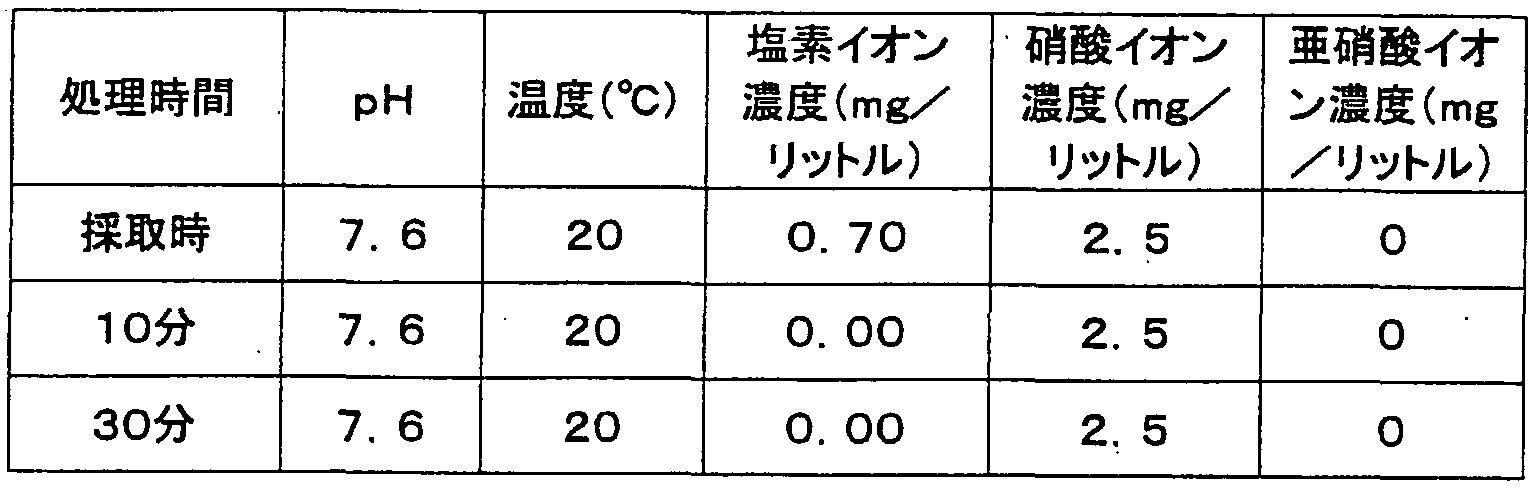


Claims
Priority Applications (3)
| Application Number | Priority Date | Filing Date | Title |
|---|---|---|---|
| US10/553,525 US7964104B2 (en) | 2003-05-02 | 2004-04-14 | Active antiseptic water or active water-based fluid, and production method and apparatus for the same |
| EP04727390A EP1632284A4 (en) | 2003-05-02 | 2004-04-14 | Active antiseptic water or active antiseptic water system fluid, and method and device for production the same |
| AU2004234223A AU2004234223A1 (en) | 2003-05-02 | 2004-04-14 | Active antiseptic water or active antiseptic water system fluid, and method and device for production the same |
Applications Claiming Priority (2)
| Application Number | Priority Date | Filing Date | Title |
|---|---|---|---|
| JP2003-127451 | 2003-05-02 | ||
| JP2003127451A JP4226387B2 (en) | 2002-07-29 | 2003-05-02 | Method for producing active, antiseptic water |
Publications (1)
| Publication Number | Publication Date |
|---|---|
| WO2004096432A1 true WO2004096432A1 (en) | 2004-11-11 |
Family
ID=33410373
Family Applications (1)
| Application Number | Title | Priority Date | Filing Date |
|---|---|---|---|
| PCT/JP2004/005324 WO2004096432A1 (en) | 2003-05-02 | 2004-04-14 | Active antiseptic water or active antiseptic water system fluid, and method and device for production the same |
Country Status (4)
| Country | Link |
|---|---|
| US (1) | US7964104B2 (en) |
| EP (1) | EP1632284A4 (en) |
| AU (1) | AU2004234223A1 (en) |
| WO (1) | WO2004096432A1 (en) |
Families Citing this family (24)
| Publication number | Priority date | Publication date | Assignee | Title |
|---|---|---|---|---|
| US20100187178A1 (en) * | 2003-01-29 | 2010-07-29 | Molycorp Minerals, Llc | Process for removing and sequestering contaminants from aqueous streams |
| US20090107919A1 (en) * | 2007-10-31 | 2009-04-30 | Chevron U.S.A. Inc. | Apparatus and process for treating an aqueous solution containing chemical contaminants |
| US20090107925A1 (en) * | 2007-10-31 | 2009-04-30 | Chevron U.S.A. Inc. | Apparatus and process for treating an aqueous solution containing biological contaminants |
| US8349764B2 (en) | 2007-10-31 | 2013-01-08 | Molycorp Minerals, Llc | Composition for treating a fluid |
| AR074321A1 (en) * | 2008-11-11 | 2011-01-05 | Molycorp Minerals Llc | REMOVAL OF OBJECTIVE MATERIALS USING RARE LAND METALS |
| TW201038510A (en) * | 2009-03-16 | 2010-11-01 | Molycorp Minerals Llc | Porous and durable ceramic filter monolith coated with a rare earth for removing contaminates from water |
| WO2010118368A1 (en) * | 2009-04-09 | 2010-10-14 | Molycorp Minerals Llc | Use of a rare earth for the removal of antimony and bismuth |
| RU2445272C1 (en) * | 2010-10-07 | 2012-03-20 | Андрей Николаевич Беляев | Method of decontaminating water with synergetic action |
| SE536086C2 (en) * | 2010-10-20 | 2013-04-30 | Wallenius Water Ab | Method and apparatus for purifying opaque liquids with light |
| US20120097550A1 (en) * | 2010-10-21 | 2012-04-26 | Lockhart Michael D | Methods for enhancing water electrolysis |
| WO2012057736A1 (en) * | 2010-10-26 | 2012-05-03 | Empire Technology Development Llc | Water treatment apparatus and systems |
| WO2012118986A1 (en) * | 2011-03-01 | 2012-09-07 | Molycorp Minerals Llc | Contaminant removal from waters using rare earths |
| US9233863B2 (en) | 2011-04-13 | 2016-01-12 | Molycorp Minerals, Llc | Rare earth removal of hydrated and hydroxyl species |
| EP2567712A1 (en) * | 2011-09-07 | 2013-03-13 | Tetra Laval Holdings & Finance S.A. | Microbial reduction in liquid |
| WO2013082294A1 (en) | 2011-12-02 | 2013-06-06 | AquaMost, Inc. | Apparatus and method for treating aqueous solutions and contaminants therein |
| US8398828B1 (en) | 2012-01-06 | 2013-03-19 | AquaMost, Inc. | Apparatus and method for treating aqueous solutions and contaminants therein |
| US9045357B2 (en) | 2012-01-06 | 2015-06-02 | AquaMost, Inc. | System for reducing contaminants from a photoelectrocatalytic oxidization apparatus through polarity reversal and method of operation |
| CN203130291U (en) * | 2013-01-22 | 2013-08-14 | 杨德利 | Device for improving fuel firing rate of internal combustion engine by magnet, photocatalyst and light effect |
| MX2015010269A (en) | 2013-02-11 | 2016-05-10 | Aquamost Inc | Apparatus and method for treating aqueous solutions and contaminants therein. |
| MX370462B (en) | 2014-03-07 | 2019-12-13 | Secure Natural Resources Llc | Cerium (iv) oxide with exceptional arsenic removal properties. |
| EP2957177A1 (en) * | 2014-06-16 | 2015-12-23 | Carag AG | Device for pasteurization of human milk |
| CN106186543B (en) * | 2016-08-17 | 2019-04-23 | 广西国宏智鸿环境科技发展有限公司 | A kind of dual-membrane type solar energy sewage-treatment plant and its technique |
| CN107055895A (en) * | 2017-06-16 | 2017-08-18 | 云南大学 | The vertical plug-flow photocatalysis treatment of waste water skid mounted equipment of diffusion in a kind of upper cloth stream |
| US10103478B1 (en) * | 2017-06-23 | 2018-10-16 | Amazon Technologies, Inc. | Water resistant connectors with conductive elements |
Citations (3)
| Publication number | Priority date | Publication date | Assignee | Title |
|---|---|---|---|---|
| JPS6214777A (en) * | 1985-07-15 | 1987-01-23 | Shunzo Miyazaki | Canned drink and production thereof |
| JPH07185340A (en) * | 1993-12-27 | 1995-07-25 | Raizaa Kogyo Kk | Method for washing and regenerating catalytic fine particles used for photooxidation treatment |
| JP2000263049A (en) * | 1999-03-18 | 2000-09-26 | Toto Kagaku Kogyo Kk | Method and apparatus for cleaning barn effluent |
Family Cites Families (32)
| Publication number | Priority date | Publication date | Assignee | Title |
|---|---|---|---|---|
| JPH0671544B2 (en) | 1990-03-26 | 1994-09-14 | 日本テクノ株式会社 | Method and apparatus for stirring liquid in liquid tank |
| US5375926A (en) * | 1992-09-14 | 1994-12-27 | Nihon Techno Kabushiki Kaisha | Apparatus for mixing and dispensing fluid by flutter of vibrating vanes |
| JP2762388B2 (en) | 1992-09-14 | 1998-06-04 | 日本テクノ株式会社 | Fluid mixing and dispersing machine |
| JP2707530B2 (en) | 1992-12-28 | 1998-01-28 | 日本テクノ株式会社 | Plating method |
| JP3244334B2 (en) | 1993-03-26 | 2002-01-07 | 日本テクノ株式会社 | Chemical plating equipment |
| JP3035114B2 (en) | 1993-04-01 | 2000-04-17 | 日本テクノ株式会社 | Electrodeposition equipment |
| JP3142417B2 (en) | 1993-04-20 | 2001-03-07 | 日本テクノ株式会社 | Stirrer |
| JP2992177B2 (en) | 1993-05-17 | 1999-12-20 | 日本テクノ株式会社 | Chrome barrel plating equipment |
| JP2989440B2 (en) | 1993-08-06 | 1999-12-13 | 日本テクノ株式会社 | Chrome plating method |
| JP2911350B2 (en) | 1993-11-02 | 1999-06-23 | 日本テクノ株式会社 | Surface treatment method and surface treatment device used therefor |
| JP2852878B2 (en) | 1994-12-26 | 1999-02-03 | 日本テクノ株式会社 | Stirrer |
| JP2767771B2 (en) | 1995-04-13 | 1998-06-18 | 日本テクノ株式会社 | Wastewater treatment equipment by electrolytic oxidation |
| US5875384A (en) * | 1995-06-12 | 1999-02-23 | California Institute Of Technology | TiO2 -coated fiber optic cable reactor |
| JP2911393B2 (en) | 1995-07-25 | 1999-06-23 | 日本テクノ株式会社 | Method and apparatus for producing fertilizer aqueous solution from electroless nickel plating wastewater |
| DE69729513T2 (en) * | 1996-02-28 | 2005-05-25 | Hoya Corp. | FILTER DEVICE WITH PHOTO CATALYST |
| JP3320984B2 (en) | 1996-08-02 | 2002-09-03 | 日本テクノ株式会社 | Stirrer for high viscosity fluid |
| JPH10309453A (en) | 1997-05-12 | 1998-11-24 | Nippon Techno Kk | Small vibration agitator |
| JP2988624B2 (en) | 1997-10-21 | 1999-12-13 | 日本テクノ株式会社 | Plating method |
| JP3196890B2 (en) | 1998-03-10 | 2001-08-06 | 日本テクノ株式会社 | Multi-shaft vibration stirrer |
| JP3854006B2 (en) | 1999-05-07 | 2006-12-06 | 日本テクノ株式会社 | Vibrating fluid agitator |
| JP3514698B2 (en) | 2000-04-04 | 2004-03-31 | 日本テクノ株式会社 | Chemical polishing of metal articles |
| IL135843A0 (en) | 2000-04-28 | 2001-05-20 | Ende Michael | Method for production of enhanced traceable and immunising drinking water and other liquids and gases, and devices for use thereof |
| JP3676694B2 (en) | 2000-05-02 | 2005-07-27 | 日本テクノ株式会社 | Vibration agitator for sterilization, sterilizer including the same, and sterilization method |
| US6605252B2 (en) * | 2000-05-02 | 2003-08-12 | Japan Techno Co., Ltd. | Vibrationally stirring apparatus for sterilization, sterilizing apparatus and sterilizing method |
| JP2002047936A (en) | 2000-07-31 | 2002-02-15 | Mitsubishi Heavy Ind Ltd | Cooling water treatment method and its device in apparatus and equipment having closed circulation cooling water system for diesel engine or the like using acid salt corrosion inhibitor |
| US6447720B1 (en) | 2000-07-31 | 2002-09-10 | Remotelight, Inc. | Ultraviolet fluid disinfection system and method |
| US6447721B1 (en) | 2000-07-31 | 2002-09-10 | Remotelight, Inc. | Drinking water UV disinfection system and method |
| JP3727846B2 (en) | 2000-12-26 | 2005-12-21 | 日本テクノ株式会社 | Sterilization method using sterilizing particles |
| JP3970523B2 (en) | 2001-01-17 | 2007-09-05 | 日本テクノ株式会社 | Vibrating flow stirring apparatus, sterilizing vibration stirring apparatus, and sterilization method using the same |
| CA2451600C (en) | 2001-06-25 | 2010-01-19 | Japan Techno Co., Ltd. | Vibratingly stirring apparatus, and device and method for processing using the stirring apparatus |
| WO2003037504A1 (en) * | 2001-11-02 | 2003-05-08 | Japan Techno Co., Ltd. | Vibratory stirrer for sterilization and sterilizer and sterilization method employing vibratory stirrer |
| JP3831299B2 (en) | 2002-06-06 | 2006-10-11 | 日本テクノ株式会社 | Food cleaning and sterilization equipment and method |
-
2004
- 2004-04-14 US US10/553,525 patent/US7964104B2/en active Active
- 2004-04-14 AU AU2004234223A patent/AU2004234223A1/en not_active Abandoned
- 2004-04-14 EP EP04727390A patent/EP1632284A4/en not_active Withdrawn
- 2004-04-14 WO PCT/JP2004/005324 patent/WO2004096432A1/en active Application Filing
Patent Citations (3)
| Publication number | Priority date | Publication date | Assignee | Title |
|---|---|---|---|---|
| JPS6214777A (en) * | 1985-07-15 | 1987-01-23 | Shunzo Miyazaki | Canned drink and production thereof |
| JPH07185340A (en) * | 1993-12-27 | 1995-07-25 | Raizaa Kogyo Kk | Method for washing and regenerating catalytic fine particles used for photooxidation treatment |
| JP2000263049A (en) * | 1999-03-18 | 2000-09-26 | Toto Kagaku Kogyo Kk | Method and apparatus for cleaning barn effluent |
Non-Patent Citations (1)
| Title |
|---|
| See also references of EP1632284A4 * |
Also Published As
| Publication number | Publication date |
|---|---|
| EP1632284A1 (en) | 2006-03-08 |
| US7964104B2 (en) | 2011-06-21 |
| AU2004234223A1 (en) | 2004-11-11 |
| US20080050471A1 (en) | 2008-02-28 |
| EP1632284A4 (en) | 2009-12-16 |
Similar Documents
| Publication | Publication Date | Title |
|---|---|---|
| WO2004096432A1 (en) | Active antiseptic water or active antiseptic water system fluid, and method and device for production the same | |
| AU2005292966B2 (en) | Neutral electrolytic water, neutral electrolytic water production method, and neutral electrolytic water production device | |
| CN100586352C (en) | Food purification apparatus | |
| TW548130B (en) | Vibrational stirring apparatus for sterilizator, apparatus and method for sterilization using the same | |
| US20100192987A1 (en) | Method and technical embodiment for the cleaning of surfaces by means of a high-pressure cleaning device using electrolyzed water by using oxidative free radicals | |
| Tsolaki et al. | Electrochemical disinfection of simulated ballast water using Artemia salina as indicator | |
| CN201239044Y (en) | Food purification apparatus | |
| JP4226387B2 (en) | Method for producing active, antiseptic water | |
| JP3676694B2 (en) | Vibration agitator for sterilization, sterilizer including the same, and sterilization method | |
| US20130284649A1 (en) | Advanced on-site water sanitization system having chlorine generation integrated with copper/silver ionization | |
| US20060175253A1 (en) | Systems and methods for generation of low zeta potential mineral crystals to enhance quality of liquid solutions | |
| KR101248571B1 (en) | Complex electrolysis apparatus for sterilization and disinfection | |
| JP2014033955A (en) | Chlorine dioxide gas sterilizer/pure chlorine dioxide solution generator | |
| KR101903387B1 (en) | Electric Device | |
| JP3831299B2 (en) | Food cleaning and sterilization equipment and method | |
| CN214903405U (en) | Subacidity hypochlorous acid antiseptic solution generating device convenient to adjust | |
| TW200932956A (en) | Configurable ozone generators | |
| KR101956575B1 (en) | Electrolysis apparatus for producing between germicide and detergent | |
| CN2793058Y (en) | Sterilizing water maker by electrolysis | |
| JP5345080B2 (en) | Drinking water for egg-collecting chicken, poultry farming method using the same, and egg produced thereby | |
| CN210393802U (en) | Drinking machine | |
| TWI276608B (en) | Vibration agitating device for sterilization, sterilization apparatus having such vibration agitating device, and sterilization method | |
| KR20150093293A (en) | Method for Preparing Sterilized Water using Seawater and Sterilization System for Marine Products | |
| CN217773817U (en) | Household ozone water generator | |
| JP2004290949A (en) | Sterilizing liquid preparation apparatus and small-sized simple water purifier with the same |
Legal Events
| Date | Code | Title | Description |
|---|---|---|---|
| AK | Designated states |
Kind code of ref document: A1 Designated state(s): AE AG AL AM AT AU AZ BA BB BG BR BW BY BZ CA CH CN CO CR CU CZ DE DK DM DZ EC EE EG ES FI GB GD GE GH GM HR HU ID IL IN IS KE KG KP KR KZ LC LK LR LS LT LU LV MA MD MG MK MN MW MX MZ NA NI NO NZ OM PG PH PL PT RO RU SC SD SE SG SK SL SY TJ TM TN TR TT TZ UA UG US UZ VC VN YU ZA ZM ZW |
|
| AL | Designated countries for regional patents |
Kind code of ref document: A1 Designated state(s): BW GH GM KE LS MW MZ SD SL SZ TZ UG ZM ZW AM AZ BY KG KZ MD RU TJ TM AT BE BG CH CY CZ DE DK EE ES FI FR GB GR HU IE IT LU MC NL PL PT RO SE SI SK TR BF BJ CF CG CI CM GA GN GQ GW ML MR NE SN TD TG |
|
| 121 | Ep: the epo has been informed by wipo that ep was designated in this application | ||
| WWE | Wipo information: entry into national phase |
Ref document number: 2004727390 Country of ref document: EP |
|
| WWE | Wipo information: entry into national phase |
Ref document number: 2004234223 Country of ref document: AU |
|
| ENP | Entry into the national phase |
Ref document number: 2004234223 Country of ref document: AU Date of ref document: 20040414 Kind code of ref document: A |
|
| WWP | Wipo information: published in national office |
Ref document number: 2004234223 Country of ref document: AU |
|
| WWP | Wipo information: published in national office |
Ref document number: 2004727390 Country of ref document: EP |
|
| WWE | Wipo information: entry into national phase |
Ref document number: 10553525 Country of ref document: US |
|
| WWP | Wipo information: published in national office |
Ref document number: 10553525 Country of ref document: US |