明 細 書 水素または合成ガス製造用触媒及び水素または合成ガスの製造方法 技 術 分 野 Description Hydrogen or synthesis gas production catalyst and hydrogen or synthesis gas production method
本発明は、 ジメチルエーテルと水蒸気または二酸化炭素が含まれる混合ガスか ら水素または合成ガスを生成させる触媒及びそれを用いた水素または合成ガスの 製造方法に関するものである。 The present invention relates to a catalyst for producing hydrogen or synthesis gas from a mixed gas containing dimethyl ether and water vapor or carbon dioxide, and a method for producing hydrogen or synthesis gas using the catalyst.
背 景 技 術 Background technology
合成ガスは、 一酸化炭素と水素からなるガスであり、 直接、 メタノール合成、 ォキソ合成、 フィッシャートロプシュ合成等の原料ガスに用いられるほか、 アン モニァ合成や各種化学製品の原料として広い用途をもっている。 Synthetic gas is a gas consisting of carbon monoxide and hydrogen, and is used directly as a raw material gas for methanol synthesis, oxo synthesis, Fischer-Tropsch synthesis, etc., and has a wide range of uses as a raw material for ammonia synthesis and various chemical products.
従来、 合成ガスを製造する方法、 あるいはそれを利用した水素を製造する方法 はいくつか知られている。 Heretofore, there have been known several methods for producing synthesis gas or producing hydrogen using the same.
例えば、 (1)石炭のガス化による方法、 (2)天然ガス、 L P G、 ナフサなどを原 料とする炭化水素の水蒸気改質方法、 (3)天然ガス、 L P G、 ナフサ、 重質油な どを原料とする炭化水素の部分酸化方法などがある。 Examples include (1) coal gasification, (2) steam reforming of natural gas, LPG, naphtha, etc., and (3) natural gas, LPG, naphtha, heavy oil, etc. There is a method for partially oxidizing hydrocarbons using as a raw material.
しかしながら、 上記(1)の石炭ガス化法においては、 極めて複雑でかつ高価な 石炭ガス化炉が必要であり、装置が大規模なブラントとなるなどの問題があった。 また (2)の炭化水素の水蒸気改質方法においては、 反応が大きな吸熱であり、 反 応の進行に 700〜1200°Cの高温を必要とするため、 特殊な改質炉が必要であり、 また使用する触媒に高い耐熱性が要求されるなどの問題があつた。 上記 (3)の炭 化水素の部分酸化方法においても、 1200〜 1500DCの高温を必要とするために特 殊な部分酸化炉が必要であり、 また反応に伴って大量のすすが生成するためその 処理が問題となり、 さらに触媒を使用する場合には触媒表面に炭素質物質が多量
に析出して触媒が劣化するなどの問題があった。 However, the coal gasification method (1) requires an extremely complicated and expensive coal gasification furnace, and has a problem that the equipment becomes a large-scale blunt. In addition, in the hydrocarbon steam reforming method (2), a special reforming furnace is required because the reaction is a large endothermic and requires a high temperature of 700 to 1200 ° C for the reaction to proceed. In addition, there is a problem that a high heat resistance is required for the catalyst to be used. Also in the partial oxidation process of carbon hydride (3), requires special partial oxidation furnace requires a high temperature of 1200 to 1500 D C, also a large amount of soot is generated in accordance with the reaction Therefore, its treatment becomes a problem, and when a catalyst is used, a large amount of carbonaceous material is present on the catalyst surface. And the catalyst deteriorates.
本発明は、 上記従来の問題点を解決し、 低温において高い収率で水素あるいは 合成ガスを得ることができる触媒及び製造方法を提供することを目的とする。 発 明 の 開 示 An object of the present invention is to solve the above conventional problems and to provide a catalyst and a production method capable of obtaining hydrogen or a synthesis gas at a low temperature and a high yield. Disclosure of the invention
本発明者らは、 上記課題を解決するべく鋭意検討の結果、 原料ガスとしてジメ チルエーテルに着目するに至った。 そして、 ジメチルエーテルと水蒸気または二 酸化炭素を反応させて水素あるいは合成ガスを生成させる触媒として、 銅、 鉄、 コノくノレ ト、 パラジウム、 イリジウム、 白金、 ロジウムおよびニッケルが極めて有 効であり、 低温で効率よく水素または合成ガスを生成させうることを見出して本 発明を完成することができた。 The present inventors have conducted intensive studies to solve the above-mentioned problems, and as a result, came to pay attention to dimethyl ether as a raw material gas. Copper, iron, conocene, palladium, iridium, platinum, rhodium and nickel are very effective as catalysts for producing hydrogen or synthesis gas by reacting dimethyl ether with steam or carbon dioxide. The inventors have found that hydrogen or synthesis gas can be generated efficiently, and completed the present invention.
すなわち、 本発明は、 活性成分として銅、 鉄、 コバノレト、 パラジウム、 イリジ ゥム、 白金、 ロジウムまたはニッケルを含有する、 ジメチルエーテルと水蒸気ま たは二酸化炭素ガスよりなる混合ガスから水素ガスを生成させる触媒と、 ジメチ ルエーテルと水蒸気または二酸化炭素を含有する混合ガスに上記触媒を接触させ ることを特徴とする水素または合成ガスの製造方法に関するものである。 That is, the present invention relates to a catalyst for producing hydrogen gas from a mixed gas comprising dimethyl ether and water vapor or carbon dioxide gas, which contains copper, iron, covanolate, palladium, iridium, platinum, rhodium or nickel as an active ingredient. And a method for producing hydrogen or synthesis gas, which comprises contacting the catalyst with a mixed gas containing dimethyl ether and water vapor or carbon dioxide.
図 面 の 簡 単 な 説 明 Brief explanation of drawings
図 1は、本発明の触媒を用いたリフォーマーを備えた燃料電池の構成図である。 図 2は、 ジメチルェ一テルまたは水素を用いた固体電解質型燃料電池の構成図 である。 FIG. 1 is a configuration diagram of a fuel cell provided with a reformer using the catalyst of the present invention. FIG. 2 is a configuration diagram of a solid oxide fuel cell using dimethyl ether or hydrogen.
図 3は、 ジメチルエーテルまたは水素を用いた固体電解質型燃料電池の発電特 性を示す図である。 FIG. 3 is a diagram showing the power generation characteristics of a solid oxide fuel cell using dimethyl ether or hydrogen.
図 4は、 本発明の触媒を用いて得られた水素または合成ガスを用いた原動機発 電システムの一般構成を示す系統図である。 FIG. 4 is a system diagram showing a general configuration of a motor power generation system using hydrogen or a synthesis gas obtained by using the catalyst of the present invention.
図 5は、 本発明の触媒を用いて得られた水素または合成ガスを用いた鉄鉱石還 元システムの一般構成を示す系統図である。
1 燃料電池 FIG. 5 is a system diagram showing a general configuration of an iron ore reduction system using hydrogen or synthesis gas obtained using the catalyst of the present invention. 1 Fuel cell
2 固体電解質型燃料電池 2 Solid oxide fuel cell
3 空気供給ライン 3 Air supply line
4 ジメチルェ一テル供給ライン 4 Dimethyl ether supply line
5 水蒸気供給ライン 5 Steam supply line
6 リフォーマー (改質反応器) 6 Reformer (reforming reactor)
1 1 焼結機排ガスクーラー 1 1 Sintering machine exhaust gas cooler
12, 13, 14 熱交換器 12, 13, 14 heat exchanger
15 改質反応器 15 Reforming reactor
16 燃焼器 16 Combustor
17 コンプレッサー 17 Compressor
18 ガスタービン 18 Gas turbine
19 発電機 19 Generator
20 排熱回収ボイラー 20 Waste heat recovery boiler
21 熱交換器 21 Heat exchanger
22 ブロワ一 22 Blower
23 改質反応器 23 Reforming reactor
24 加熱炉 24 heating furnace
25 鉄鉱石還元炉 25 Iron ore reduction furnace
発明を実施するための最良の形態 BEST MODE FOR CARRYING OUT THE INVENTION
本発明の触媒は、 ジメチルエーテルと水蒸気または二酸化炭素よりなる混合ガ スから水素ガスを生成させるものであり、 銅、 鉄、 コバルト、 パラジウム、 イリ ジゥム、 白金、 ロジウムまたはニッケルを活性成分とするものである。 The catalyst of the present invention generates hydrogen gas from a mixed gas consisting of dimethyl ether and water vapor or carbon dioxide, and contains copper, iron, cobalt, palladium, iridium, platinum, rhodium or nickel as an active component. is there.
これらの活性成分のうち、 コノくルト、 パラジウム、 イリジウム、 白金、 ロジゥ ムおよびニッケルはジメチルェ一テルと水蒸気から合成ガスを生成させ、 銅、 コ
バルトおよびパラジウムはジメチルエーテルと二酸化炭素から合成ガスを生成さ せる。 すなわち、 コバルトとパラジウムは水蒸気と二酸化炭素のいずれを用いて も合成ガスを生成させることができる。 一方、 銅と鉄は水蒸気を用いると主に水 素を生成する。 Of these active ingredients, cono-kort, palladium, iridium, platinum, rhodium and nickel form syngas from dimethyl ether and water vapor, producing copper, Baltic and palladium produce syngas from dimethyl ether and carbon dioxide. That is, cobalt and palladium can generate synthesis gas using either steam or carbon dioxide. On the other hand, copper and iron mainly produce hydrogen when water vapor is used.
これらの活性成分は金属または化合物の形態で触媒に含まれている。 銅の化合 物としては銅の酸化物が好ましく、 銅の酸化物は酸化第一銅(C u 20 )、 酸化第 二銅(C u O)またはその混合物である。 鉄の化合物としては鉄の酸化物が好まし く、 鉄の酸化物は酸化銅一鉄(F e 0)、 酸化第二鉄(F e 2〇3)またはその混合物 である。 コノくノレトの化合物としてはコノくル卜の酸化物が好ましく 、 コノくノレ 卜の酸 化物は酸化第一コバルト(C o O)、 酸化第二コバルト(C o 203)またはその混合 物である。 パラジウムの化合物としてはパラジウムの酸化物および酸化物が好ま しく、 パラジウムの酸ィヒ物は酸化第一パラジウム(P d〇)、 三二酸化パラジウム ( P d 2〇3)、 酸化第二パラジウム(P d o2)、 またはその混合物であり、 パラジゥ ムの酸化物は二酸化パラジウム(P d C 1 2)、 四塩化パラジウム(P d C 1 4)また はその混合物等である。 ィリジゥムの化合物としてはィリジゥムの酸化物、 塩化 物が好ましく、 ィリジゥムの酸化物は I r 02、 塩化物は I r C 1 3である。 白金 の化合物としては白金の酸化物、 塩化物が好ましい。 白金の酸化物は P t Oおよ び P t 02であり、 塩化物は P t C 1 2、 P t C 1 3および P t C 1 4である。 口 ジゥムの化合物としてはロジウムの酸化物、 塩化物が好ましい。 ロジウムの酸化 物は R h 2〇3であり、 塩化物は R h C 1 3である。 ニッケルの化合物としては二 ッケルの硫化物が好ましく、 ニッケルの硫化物は N i S、 N i 3 S 2またはその 混合物である。 These active ingredients are contained in the catalyst in the form of a metal or a compound. Preferably oxides of copper as a compound of copper, oxides of cuprous (C u 2 0) oxidation of copper, cupric oxide (C u O) or mixtures thereof. The compound of iron rather preferred oxides of iron, oxides of copper oxide iron (F e 0) of iron, ferric oxide (F e 2 〇 3) or mixtures thereof. Preferably oxides of Konokuru I as compounds of Konoku Noreto, Konoku Honoré oxides of I of cobalt (C o O) oxide, the second cobalt (C o 2 0 3) or mixtures thereof It is. The compounds of palladium lay preferred are oxides and oxides of palladium, an acid I arsenide of palladium first palladium (P D_〇) oxide, sesquioxide palladium (P d 2 〇 3), (II) oxide palladium (P do 2), or a mixture thereof, oxides dioxide palladium (P d C 1 2 of Parajiu beam), the four-palladium chloride (P d C 1 4) or a mixture thereof and the like. Oxide Irijiumu as compounds of Irijiumu, chlorides are preferred, oxides Irijiumu is I r 0 2, chloride is I r C 1 3. Platinum compounds are preferably platinum oxides and chlorides. Oxides of platinum is P t O and P t 0 2, the chloride is P t C 1 2, P t C 1 3 and P t C 1 4. Rhodium oxides and chlorides are preferred as the compound of the mouth dime. Oxides of rhodium is R h 2 〇 3, the chloride is R h C 1 3. Preferably sulfides nickel as nickel compound, sulfide nickel is N i S, N i 3 S 2 or a mixture thereof.
本発明の触媒は、 触媒担体に担持させて使用することができる。 好ましレ、触媒 担体としては、 アルミナ、 シリカゲル、 シリカ ·アルミナ、 ゼォライ ト、 チタ二 ァ、 ジノレコユア、 酸化亜鉛、 酸化スズ、 酸化ランタン、 酸化セリウムなどの酸化
物であるが、 なかでもアルミナが合成ガス収率が高いので好ましい。 触媒中の含 有率は、 銅の場合には約 1〜50 重量%、 好ましくは約 3〜30 重量。/。であり、 鉄 の場合には約 10〜100重量。/。、 好ましくは約 30〜100重量。/。であり、 コバルトの 場合には約 1〜30 重量。 /0、 好ましくは約 3〜 15 重量。 であり、 イリジウム、 白 金およびロジウムの場合には約 0. 05〜10 重量。 /0、 好ましくは約 0. 1〜5重量% であり、 ニッケルの場合には約 0. 5〜30 重量。/。、 好ましくは約 1〜 重量%で ある。 含有率がこれらの範囲外であると、 水素や合成ガスの収率が低下する。 また、 本発明の触媒には、 上記の金属またはその化合物のほかに他の金属ある レ、は化合物を併せて用いることができる。 他の金属および化合物の例としては、 銅触媒の場合には、 亜鉛、 クロム、 ニッケル、 マンガン、 スズ、 セリウム、 ラン タンぉよびこれらの化合物を挙げることができる。 これらの第 3成分の含有率は 70重量%以下、特に 50重量。/。以下であり、含有させる場合は、通常 1〜30重量。 /0 程度である。 The catalyst of the present invention can be used by being supported on a catalyst carrier. Preferable catalyst carriers include alumina, silica gel, silica-alumina, zeolite, titania, dinorecoure, zinc oxide, tin oxide, lanthanum oxide, cerium oxide, etc. Of these, alumina is preferred because of its high synthesis gas yield. The content in the catalyst is about 1 to 50% by weight in the case of copper, preferably about 3 to 30% by weight. /. In the case of iron, about 10-100 weight. /. , Preferably about 30-100 weight. /. Approximately 1 to 30 weight for cobalt. / 0 , preferably about 3-15 weight. And about 0.05 to 10 weight for iridium, platinum and rhodium. / 0 , preferably about 0.1-5% by weight, in the case of nickel about 0.5-30% by weight. /. Preferably, it is about 1% by weight. If the content is outside these ranges, the yields of hydrogen and synthesis gas decrease. In the catalyst of the present invention, in addition to the above-mentioned metals or compounds thereof, other metals or compounds may be used in combination. Examples of other metals and compounds include, in the case of copper catalysts, zinc, chromium, nickel, manganese, tin, cerium, lanthanum and these compounds. The content of these third components is 70% by weight or less, especially 50% by weight. /. Below, if included, usually 1-30 weight. / 0 or so.
鉄触媒の場合の他の金属および化合物の例としては、 亜鉛、 ニッケル、 クロム、 マンガン、 スズ、 セリウム、 ランタンおよびそれらの化合物を挙げることができ る。 これらのなかで、 特に亜鉛、 ニッケル、 クロムおよびマンガンの酸化物が好 ましい。 これらの第 3成分の含有率は 50重量%以下、特に 30重量%以下であり、 含有させる場合は、 通常 1〜20重量%程度である。 コバルト触媒の場合の他の金 属および化合物の例としては二ッケル、 鉄の金属及びそれらの化合物を挙げるこ とができる。 これらの第 3成分の含有率は 20重量。 /0以下、 特に 10重量。 /0以下で あり、 含有させる場合は、 通常 1〜5重量。 /0程度である。 Examples of other metals and compounds in the case of iron catalysts include zinc, nickel, chromium, manganese, tin, cerium, lanthanum and their compounds. Of these, zinc, nickel, chromium and manganese oxides are particularly preferred. The content of these third components is 50% by weight or less, particularly 30% by weight or less, and when they are contained, they are usually about 1 to 20% by weight. Examples of other metals and compounds in the case of cobalt catalysts include nickel, iron metals and their compounds. The content of these third components is 20% by weight. / 0 or less, especially 10 weight. / 0 or less, and if included, usually 1 to 5 weight. / 0 or so.
イリジウム触媒、 白金触媒、 およびロジウム触媒の場合の他の金属および化合 物の例としては銅、 コバルト、 ニッケル、 鉄の金属及びそれらの化合物を挙げる ことができる。 これらの第 3成分の含有率は 20重量%以下、 特に 10重量。 /0以 下であり、 含有させる場合は、 通常 1〜 5重量%程度である。
ニッケル触媒の場合の他の金属および化合物の例としては銅、 コバルト、 鉄の 金属及び/又は化合物を挙げることができる。 また、 これらの第 3成分の含有率 は 20重量%以下、 特に 10重量%以下であり、 含有させる場合は、 通常 1〜5重 量%程度である。 Examples of other metals and compounds in the case of iridium, platinum, and rhodium catalysts include copper, cobalt, nickel, iron metals and compounds thereof. The content of these third components is 20% by weight or less, especially 10% by weight. / 0 or less, and when it is contained, it is usually about 1 to 5% by weight. Examples of other metals and compounds in the case of nickel catalysts include metals and / or compounds of copper, cobalt and iron. The content of these third components is 20% by weight or less, particularly 10% by weight or less, and when they are contained, they are usually about 1 to 5% by weight.
上記第 3成分はレ、ずれも単独で用いるほか 2種以上を混合して用いることもで さる。 The third component may be used alone or in combination with two or more types.
パラジウム触媒の場合には、 塩基性を有する金属酸化物に担持させることが好 ましい。 塩基性を有する金属酸化物は、 L i2〇、 Na20、 K20、 R b20、 C s2〇等のアルカリ金属の酸化物、 B e O、 MgO、 C a O、 S r O、 B a〇等 のアル力リ土類金属の酸化物、 Y203、 L a2〇3、 C e 02等の希土類元素の酸化 物、 Zn〇、 S n02、 Z r〇2、 A 12〇3、 T i 02および前記の金属酸化物の 2 種以上の混合物である。 また前記の塩基性を有する金属酸化物を、 塩基性を有し ない他の金属酸化物、 例えばシリ力ゲルなど、 あるレ、は塩基性を有しなレ、他の化 合物、 例えば炭化珪素、 活性炭などと ¾iみ合わせて用いることができる。 パラジ ゥムの担持率は、 塩基性を有する金属酸化物に対して約 0.1〜30重量。 /0、 好まし くは 0.2〜20重量。 /。である。 パラジウムの担持率が約 0.1重量。 /0未満および 30 重量。 /0以上であると、 合成ガスの収率が低下する。 In the case of a palladium catalyst, it is preferable to support it on a basic metal oxide. Metal oxide having a basicity, L i 2 〇, Na 2 0, K 2 0 , R b 2 0, C s 2 alkali metal oxides such as 〇, B e O, MgO, C a O, S r O, B A_〇 like Al force Li earth metal oxides of, Y 2 0 3, L a 2 〇 3, oxides of C e 0 2 or the like of rare earth elements, Zn_〇, S n0 2, Z r a 〇 2, a 1 2 〇 3, T i 0 2, and mixtures of two or more of said metal oxides. Further, the above-mentioned basic metal oxide may be replaced with another non-basic metal oxide, for example, a silica gel. It can be used in combination with silicon or activated carbon. The loading ratio of palladium is about 0.1 to 30 weight based on the basic metal oxide. / 0 , preferably 0.2-20 weight. /. It is. The loading rate of palladium is about 0.1 weight. / Less than 0 and 30 weight. When the ratio is / 0 or more, the yield of synthesis gas decreases.
この塩基性を有する金属酸化物を活性成分であるパラジウムの担体として用い ることにより、 メタンを主体とする炭化水素の生成を抑制して、 高収率で合成ガ スを生成させる。 By using this basic metal oxide as a carrier for palladium as an active ingredient, the production of hydrocarbons mainly composed of methane is suppressed, and synthetic gas is produced in high yield.
パラジウム担持金属酸化物に固体酸性化合物を組み合わせて使用することも有 効であり、 この触媒を用いることによってジメチルエーテルと水蒸気から合成ガ スを生成させることができる。 この触媒は、 金属酸化物にパラジウムを担持させ たものと、 固体 g針生を有する化合物とを物理的に混合して成る触媒である。 It is also effective to use a solid acidic compound in combination with a palladium-supported metal oxide. By using this catalyst, a synthetic gas can be generated from dimethyl ether and steam. This catalyst is a catalyst obtained by physically mixing a metal oxide having palladium supported thereon and a compound having solid g needles.
パラジウムの担持に使用される金属酸化物は、 シリカゲル、 チタニア、 アルミ
ナ、 シリカ 'アルミナ、 ジルコニァ、 酸化スズ、 酸化亜鉛等であるが、 なかでも シリカゲルおよびチタニアが合成ガスの収率が高いので好ましレ、。 金属酸化物に 担持させるパラジウムは、 金属酸化物に対して約 0.05〜30 重量%、 好ましくは 0.1〜20重量。/。である。パラジゥムの担持率が約 0.05重量。/。未満および 30重量。 /0 以上であると、 合成ガスの収率が低下する。 また本発明の触媒を構成する一方の 触媒成分には、 パラジウムのほかに他の金属あるいは化合物を併せて用いること ができる。 他の金属および化合物の例としては、 L i2〇、 Na20、 K20、 R b 2〇、 C s2〇等のアルカリ金属の酸化物、 B e O、 MgO、 Ca O、 S r 0、 B a〇などのアル力リ土類金属の酸化物、 Y203、 L a2〇3、 C e 02等の希土類元 素の酸化物および前記の金属酸化物の 2種以上の混合物である。 これら第 3成分 の含有率は 20重量。 /0以下、 特に 10重量。 /0以下であり、 含有させる場合は、 通常 1〜 5重量。 /0程度である。 Metal oxides used to support palladium include silica gel, titania, and aluminum Silica, alumina, zirconia, tin oxide, zinc oxide, etc. Among them, silica gel and titania are preferred because of high synthesis gas yield. The amount of palladium supported on the metal oxide is about 0.05 to 30% by weight, preferably 0.1 to 20% by weight, based on the metal oxide. /. It is. Palladium loading rate is about 0.05 weight. /. Less than and 30 weight. When the ratio is / 0 or more, the yield of synthesis gas decreases. Further, as one of the catalyst components constituting the catalyst of the present invention, other metals or compounds can be used in addition to palladium. Examples of other metals and compounds, L i 2 〇, Na 2 0, K 2 0 , R b 2 〇, oxides of alkali metals, such as C s 2 〇, B e O, MgO, Ca O, S r 0, B Al force Li earth metal oxides such as A_〇, Y 2 0 3, L a 2 〇 3, two C e 0 oxides of rare-earth elements of 2, and the like and the metal oxide It is a mixture of the above. The content of these third components is 20% by weight. / 0 or less, especially 10 weight. / 0 or less, if included, usually 1-5 weight. / 0 or so.
固体酸性を有する化合物は、 ァノレミナ、 シリカ 'アルミナ、 シリカ 'チタニア、 ゼォライ ト、 燐酸アルミニウム等である力;、 なかでもアルミナが合成ガスの収率 が高いので好ましい。 Compounds having solid acidity are anolemina, silica 'alumina, silica' titania, zeolite, aluminum phosphate, and the like; among them, alumina is preferred because of high synthesis gas yield.
この触媒においては、 固体酸を有する化合物の触媒作用により、 ジメチルェ一 テルを加水分解してメタノールを生成させ(( 1 )式)、 っレ、で生成したメタノール を、 金属酸化物にパラジウムを担持させた触媒に接触させ、 メタノールを分解し て合成ガスを生成させるものであり((2)式)、 上記の 2種類の触媒を物理的に混 合して使用することにより、 高収率で合成ガスを得ることができる。 In this catalyst, the dimethyl ether is hydrolyzed to form methanol by the catalytic action of a compound having a solid acid (formula (1)), and the methanol generated in step (1) is loaded with palladium on a metal oxide. The catalyst is brought into contact with the oxidized catalyst to decompose methanol to produce synthesis gas (Equation (2)). By physically mixing the above two types of catalysts, a high yield can be obtained. Syngas can be obtained.
CH3OCH3 + H20 → 2 C H 3 O H ( 1 ) CH 3 OCH 3 + H 2 0 → 2 CH 3 OH (1)
CH3OH → CO+ 2H2 (2) CH 3 OH → CO + 2H 2 (2)
上記各触媒の製造には、 この種の触媒の一般的な調整方法を適用できる。 例え ば触媒の製造用原料は、 触媒活性成分金属の化合物として、 硝酸塩、 炭酸塩、 ハ 口ゲン化物等の無機酸塩および酢酸塩、 シュゥ酸塩など有機酸塩が使用される。
また、 触媒担体への活性成分の担持操作には、 通常の沈殿法、 混練法、 含浸法お よびイオン交換法などの技術が利用できる。このように調製された触 且成物は、 必要があれば常法により焼成する。焼成は、窒素中または空気中において、 300〜 800°Cの温度で 1〜10時間加熱して行うのが好ましレ、。 For the production of each of the above-mentioned catalysts, a general adjustment method for this type of catalyst can be applied. For example, as a raw material for the production of a catalyst, inorganic acid salts such as nitrates, carbonates, and haptic compounds, and organic acid salts such as acetates and oxalates are used as compounds of the catalytically active component metal. For the operation of loading the active ingredient on the catalyst carrier, techniques such as ordinary precipitation, kneading, impregnation, and ion exchange can be used. The catalyst thus prepared is fired by a conventional method, if necessary. The calcination is preferably performed by heating at a temperature of 300 to 800 ° C. for 1 to 10 hours in nitrogen or air.
また触媒は反応を行う前に活性化処理を行うのがよく、 金属触媒等の場合には 水素雰囲気において、 300〜600°Cの温度で、 1〜10時問処理するのが好ましい。 一方、 酸化物触媒の時には事前活性化処理は不要である。 硫化物の場合には、 硫 化水素 (H 2 S )、 ジメチルスルフイ ド (C H 3 S C H 3 ) またはジメチルジス ルフイ ド (C H 3 S S C H 3 ) を 1〜50%含む水素の雰囲気下で、 30()〜600°C の温度において 1〜10時問処理するのが好ましい。 The catalyst is preferably subjected to an activation treatment before the reaction. In the case of a metal catalyst or the like, it is preferable to perform the treatment in a hydrogen atmosphere at a temperature of 300 to 600 ° C. for 1 to 10 hours. On the other hand, in the case of an oxide catalyst, no pre-activation treatment is required. In the case of sulfide, under hydrogen atmosphere containing 1 to 50% of hydrogen sulfide (H 2 S), dimethyl sulfide (CH 3 SCH 3) or dimethyl disulfide (CH 3 SSCH 3), 30 ( ) Preferably, the treatment is carried out at a temperature of -600 ° C for 1-10 hours.
二ッケルを硫化物にする時の硫化処理は常法によって行えばよく、 硫化水素、 ジメチルスルフィ ド、 ジメチルジスルフィ ド、 二硫化炭素の一種または二種以上 の混合ガス、 またはこれらと水素の混合ガスの雰囲気において、 300〜600°Cの 温度で 1〜1() 時間加熱して行うのが好ましい。 水素と上記硫黄化合物の混合比 は 1 : 0. 05〜 1 : 1程度が適当である。 Sulfidation treatment for converting nickel into sulfide may be performed by a conventional method, and one or a mixed gas of hydrogen sulfide, dimethyl sulfide, dimethyl disulfide, and carbon disulfide, or a mixture of these with hydrogen It is preferable to carry out the heating in a mixed gas atmosphere at a temperature of 300 to 600 ° C. for 1 to 1 () hour. The appropriate mixing ratio of hydrogen to the above sulfur compound is about 1: 0.05 to 1: 1.
塩基性を有する金属酸化物にパラジウムを担持させた触媒の製造の際に、 塩基 性を有する金属酸ィヒ物はパラジゥムを含む酸性の強レ、水溶液と接触すると、 塩基 性が失われる。 そこで、 この触媒の製造方法においては、 金属酸化物の塩基性を 回復するために、 金属酸化物にパラジウムを担持した後、 塩基性の水溶液で処理 することを特徴とする。 この処理操作により、 高収率で合成ガスを得ることがで きる。 すなわち塩基性を有する金属酸化物にパラジウムを担持させた後、 塩基性 の水溶液で処理することを特徴とする。 この触媒の製造方法としては、 パラジゥ ムの金属塩を含む水溶液、 例えば塩化パラジウムを含む水溶液に塩基性を有する 金属酸化物を投入して、 蒸発乾固、 乾燥の後、 焼成する。 焼成は、 窒素中または 空気中において、 350〜600°Cの温度で 1〜10 時間加熱して行うのが好ましい。
次いで、 このものを塩基性の水溶液で処理する。 塩基性の水溶液としては、 アル 力リ金属の水酸化物および炭酸塩ならびにアル力リ土類金属の水酸化物の水溶液 があげられる。 これらの塩基性化合物の濃度は 0. 5〜20 程度、 通常 1〜10 程度 が適当である。 処理は触媒に塩基性水溶液を接触させ、 次レ、で塩基性水溶液を除 去することによって行う。 この処理は常温〜 80°Cの温度において、 1〜5 時間行 うのが好ましい。 また、 塩基性の水溶液で処理した後、 例えば上記の塩基性化合 物を少量 (例えば 0. 1〜1. 0 程度)担持することもできる。 触媒は調製の最終段階 において活性化処理を行うが、 これは、 水素雰囲気下、 350〜600°Cの温度で、 1〜10時間処理するのが好ましい。 In the production of a catalyst in which palladium is supported on a basic metal oxide, the basic metal oxide loses its basicity when it comes into contact with a strongly acidic aqueous solution containing palladium or an aqueous solution. Therefore, this method for producing a catalyst is characterized in that in order to restore the basicity of the metal oxide, the metal oxide is loaded with palladium and then treated with a basic aqueous solution. By this processing operation, a synthesis gas can be obtained with a high yield. That is, the method is characterized in that palladium is supported on a basic metal oxide and then treated with a basic aqueous solution. As a method for producing this catalyst, a basic metal oxide is put into an aqueous solution containing a metal salt of palladium, for example, an aqueous solution containing palladium chloride, evaporated to dryness, dried, and then calcined. The calcination is preferably performed by heating at 350 to 600 ° C for 1 to 10 hours in nitrogen or air. This is then treated with a basic aqueous solution. Examples of the basic aqueous solution include aqueous solutions of hydroxides and carbonates of alkaline metal and hydroxides of alkaline earth metal. The concentration of these basic compounds is suitably about 0.5 to 20, usually about 1 to 10. The treatment is performed by bringing a basic aqueous solution into contact with the catalyst and removing the basic aqueous solution in the next step. This treatment is preferably performed at a temperature of room temperature to 80 ° C for 1 to 5 hours. After the treatment with a basic aqueous solution, for example, a small amount (for example, about 0.1 to 1.0) of the above-mentioned basic compound can be supported. The catalyst is subjected to an activation treatment at the final stage of the preparation, which is preferably carried out in a hydrogen atmosphere at a temperature of 350 to 600 ° C. for 1 to 10 hours.
パラジゥム担持金属酸化物と固体酸性化合物を含有する触媒におけるパラジゥ ム担持金属酸化物触媒の製造には、 この種の触媒の一般的な調製方法を適用でき る。 例えば触媒の製造用原料は、 パラジウムの化合物として硝酸塩、 炭酸塩、 ハ 口ゲン化物等の無機酸塩および酢酸パラジゥム、 シュゥ酸パラジゥムなど有機酸 塩が使用される。 また、 金属酸化物担体へのパラジウムの担持操作には、 通常の 沈殿法、 混練法、 含浸法およびイオン交換法などの技術が利用できる。 このよう に調製された触¾#且成物は、 必要があれば常法により焼成する。 焼成は、 窒素中 または空気中において、 300〜600¾の温度で 1〜10 時問加熱して行うのが好ま しい。 次いで、 水素雰囲気において、 300〜600°Cの温度で、 1〜10 時間処理す るのが好ましい。 For the production of a palladium-supported metal oxide catalyst in a catalyst containing a palladium-supported metal oxide and a solid acidic compound, a general method for preparing this type of catalyst can be applied. For example, as a raw material for producing a catalyst, inorganic salts such as nitrates, carbonates, and halides, and organic acid salts such as palladium acetate and palladium oxalate are used as palladium compounds. For the operation of loading palladium on the metal oxide carrier, techniques such as ordinary precipitation, kneading, impregnation, and ion exchange can be used. The catalyst thus prepared is calcined by a conventional method, if necessary. The calcination is preferably performed by heating at a temperature of 300 to 600 ° C for 1 to 10 hours in nitrogen or air. Next, it is preferable to perform the treatment in a hydrogen atmosphere at a temperature of 300 to 600 ° C. for 1 to 10 hours.
パラジウム担持金属酸化物と固体酸性化合物の混合方法は、 両成分をそれぞれ ペレット化したのち物理的に混合してもよく、 また、 両成分を粉末にして物理的 に混合したのち圧縮成形してペレット化してもよレ、。 両成分の混合割合は、 特に 限定されることなく、 各成分の種類あるいは反応条件などに応じて適宜選択すれ ばよいが、 通常は重量比で 1 : 10〜10: 1程度であり、 好ましくは 1 : 5〜5 : 1程度である。
このようにして調製された上記の各触媒にジメチルエーテルと水蒸気または二 酸化炭素との混合ガスを流通させることにより、 水素または合成ガスが高収率で 得られる。 As a method of mixing the palladium-supported metal oxide and the solid acidic compound, both components may be individually pelletized and then physically mixed, or both components may be powdered and physically mixed, and then compression molded and pelletized. You can make it. The mixing ratio of the two components is not particularly limited and may be appropriately selected according to the type of each component or the reaction conditions. Usually, the mixing ratio is about 1:10 to 10: 1 by weight, and is preferably 1: About 5 to 5: 1. By passing a mixed gas of dimethyl ether and steam or carbon dioxide through each of the catalysts thus prepared, hydrogen or a synthesis gas can be obtained in high yield.
本発明においては、 原料のジメチルェ一テルとともに水蒸気または二酸化炭素 を供給する。 水蒸気の場合の供給量は原料のジメチルェ一テルに対し量論量以上 であればよく、 合成ガスを生成させる場合には、 1〜20 モノレ倍、 好ましくは 1 〜10 モル倍である。 一方、 水素を生成させる場合には 1〜30 モル倍好ましくは 1〜20 モルである。 水蒸気の供給が 1モル倍より少ないと、 高いジメチルェ一 テル転化率が得られず、 また 20モル倍あるいは 30モル倍より多いと経済的でな レ、。 一方、 二酸化炭素の場合の供給量は原料のジメチルェ一テルに対して 0. 8〜 2. 0 モル倍、 好ましくは 0. 9〜1. 5 モル倍である。 二酸化炭素の供給が 0. 8 モル 倍より少ないと、 高いジメチルエーテル転化率が得られず、 また 2. 0モル倍より 多いと、 生成ガスに多量の二酸化炭素が残存して、 二酸化炭素の除去が必要とな り好ましくなレ、。 水蒸気と二酸化炭素を併用できることは言うまでもない。 この 原料ガスには、 ジメチルエーテルと水蒸気または二酸化炭素以外の成分も含むこ とができる。 二酸化炭素を用いた場合にその他の成分として水蒸気を加えると H 2のモル比が高くなる。 In the present invention, steam or carbon dioxide is supplied together with the raw material dimethyl ether. The supply amount of water vapor may be at least stoichiometric with respect to the dimethyl ether as the raw material, and when syngas is generated, it is 1 to 20 times, preferably 1 to 10 times. On the other hand, when hydrogen is generated, the amount is 1 to 30 moles, preferably 1 to 20 moles. If the supply of steam is less than 1 mole, a high dimethyl ether conversion cannot be obtained, and if it is more than 20 moles or 30 moles, it is not economical. On the other hand, the supply amount of carbon dioxide is 0.8 to 2.0 mole times, preferably 0.9 to 1.5 mole times with respect to the raw material dimethyl ether. If the supply of carbon dioxide is less than 0.8 mole times, a high dimethyl ether conversion cannot be obtained, and if it is more than 2.0 mole times, a large amount of carbon dioxide remains in the product gas, and the carbon dioxide is removed. Necessary and desirable. It goes without saying that steam and carbon dioxide can be used together. The source gas may contain components other than dimethyl ether and water vapor or carbon dioxide. When carbon dioxide is used, adding water vapor as another component increases the molar ratio of H 2 .
特に、 活性成分としてコバルトを用いた触媒および塩基性を有する金属酸化物 にパラジウムを担持させた触媒の場合には、 原料のジメチルエーテルとともに水 蒸気および Zまたは二酸化炭素を供給する。 水蒸気または二酸化炭素の一方を供 給する場合の供給量は上述と同じである。 一方、 水蒸気と二酸化炭素をともに供 給する場合には、 水蒸気と二酸化炭素の合計がジメチルエーテルに対して 1〜10 モル倍、 好ましくは 1〜 5モル倍である。 水蒸気と二酸ィヒ炭素の合計が 1モル倍 より少ないと、 高いジメチルエーテル転化率が得られず、 また 10 モル倍より多 レ、と経済的でなく、 また二酸化炭素の除去が必要となり好ましくない。
この原料ガスには、 ジメチルエーテルと水蒸気、 二酸化炭素以外の成分も含む ことができる。 その他の成分として反応に不活性なガス、 例えば窒素、 不活性ガ ス、 C O、 H 2、 メタン等を含むことができる。 これらの含有量は 30 容量。 /0以 下が適当であり、 これより多くなると反応速度の低下が問題になる。 一方、 空気 (酸素)はジメチノレエーテルが燃焼してしまうのでなるベく排除したほうがよく、 許容含有量は空気として 5 %以下である。 In particular, in the case of a catalyst using cobalt as an active component and a catalyst in which palladium is supported on a basic metal oxide, water vapor and Z or carbon dioxide are supplied together with the raw material dimethyl ether. The supply amount when supplying either steam or carbon dioxide is the same as above. On the other hand, when both steam and carbon dioxide are supplied, the total of steam and carbon dioxide is 1 to 10 times, preferably 1 to 5 times, the molar amount of dimethyl ether. If the sum of water vapor and carbon dioxide is less than 1 mole, a high conversion of dimethyl ether cannot be obtained, and it is not economical because it is more than 10 moles. . This raw material gas can contain components other than dimethyl ether, water vapor, and carbon dioxide. Other components may include gases inert to the reaction, for example, nitrogen, inert gases, CO, H 2 , methane, and the like. Their content is 30 volumes. A value of / 0 or less is appropriate, and if it is more than this value, a reduction in the reaction rate becomes a problem. On the other hand, air (oxygen) should be removed because it burns dimethinoleether, and its allowable content is 5% or less as air.
反応温度は、ジメチルェ一テルと水蒸気を供給して合成ガスを生成させる場合、 200°C以上、 好ましくは 250°C以上、 特に好ましくは 300°C以上でかつ、 600°C以 下、 好ましくは 500°C以下、 より好ましくは 450°C以下、 特に好ましくは 400°C 以下である。 また、 ジメチルエーテルと二酸化炭素を供給して合成ガスを生成さ せる場合は 200°C以上、 好ましくは 250°C以上、 特に好ましくは 300°C以上で、 かつ、 600°C以下、 好ましくは 500°C以下、 特に好ましくは 450°C以下である。 ジメチルエーテルと水蒸気を供給して水素を生成させる場合、 150°C以上、 好ま しくは 200°C以上、 特に好ましくは 250°C以上で、 かつ、 500°C以下、 好ましく は 450°C以下、 特に好ましくは 400°C以下である。 銅、 白金またはパラジウムを 活性成分とする触媒は低温活性が大きレ、。 反応温度が上記範囲より低いと高いジ メチルエーテル転化率が得られず、 かつ二酸化炭素の生成割合が増加して水素や 合成ガスの収率を低下させ、 また反応温度が上記範囲より高いと、 合成ガス製造 の場合にはメタンを主体とする炭化水素の生成が顕著となり、 生成物中の水素や 合成ガスの割合が低下して好ましくない。 また、 水素ガス製造の場合には、 上記 範囲より高いと副生するメタノールおよび一酸化炭素の割合が増加して水素の収 率が低下し、 特に銅触媒の場合には、 活性成分である銅の粒子成長が著しくなつ て、 徐々に触媒が失活してくるので好ましくなレ、。 The reaction temperature is 200 ° C. or higher, preferably 250 ° C. or higher, particularly preferably 300 ° C. or higher, and 600 ° C. or lower, when the dimethyl ether and steam are supplied to generate synthesis gas. It is at most 500 ° C, more preferably at most 450 ° C, particularly preferably at most 400 ° C. When dimethyl ether and carbon dioxide are supplied to generate synthesis gas, the temperature is 200 ° C or higher, preferably 250 ° C or higher, particularly preferably 300 ° C or higher, and 600 ° C or lower, preferably 500 ° C. C or lower, particularly preferably 450 ° C or lower. When hydrogen is generated by supplying dimethyl ether and steam, the temperature is 150 ° C or higher, preferably 200 ° C or higher, particularly preferably 250 ° C or higher, and 500 ° C or lower, preferably 450 ° C or lower, particularly Preferably it is 400 ° C or lower. Catalysts containing copper, platinum or palladium as active ingredients have high low-temperature activity. If the reaction temperature is lower than the above range, a high conversion of dimethyl ether cannot be obtained, and the production rate of carbon dioxide increases to lower the yield of hydrogen or synthesis gas.If the reaction temperature is higher than the above range, In the case of syngas production, the production of hydrocarbons mainly composed of methane becomes remarkable, and the proportions of hydrogen and syngas in the product are undesirably reduced. In the case of producing hydrogen gas, if the ratio is higher than the above range, the proportion of by-produced methanol and carbon monoxide increases, and the yield of hydrogen decreases. Particularly, in the case of a copper catalyst, the active component copper This is not desirable because the particle growth of the particles becomes remarkable and the catalyst gradually deactivates.
反応圧力は常圧〜 10 kgZcm2が好ましい。 反応圧力が 10 kg/cm2より高いとジ メチルエーテル転化率が低下する。
空間速度 (触媒 1 m3あたりの標準状態における混合ガスの供給速度 m: The reaction pressure is preferably from normal pressure to 10 kgZcm 2 . If the reaction pressure is higher than 10 kg / cm 2 , the conversion of dimethyl ether decreases. The feed rate of the mixed gas in the standard state per space velocity (catalyst 1 m 3 m:
は、 合成ガス製造の場合は 1000〜20000m3Zm3 · h、 水素製造の場合は 1000 〜50000m3Zm3 · h、 特に 30000m3/m3 . h以下が好ましい。 空間速度が上 記範囲より大きいとジメチルエーテル転化率が低くなり、 また上記範 fflより小さ いと反応器が極端に大きくなって経済的でない。 , If the synthesis gas production 1000~20000m 3 Zm 3 · h, 1000 ~50000m 3 Zm 3 · h in the case of hydrogen production, especially 30000m 3 / m 3. H or less. If the space velocity is larger than the above range, the conversion of dimethyl ether is low, and if it is smaller than the above range ffl, the reactor becomes extremely large and is not economical.
なお、 本発明の方法においては、 固定床、 流動床のいずれの装置を用いてもよ レ、。 In the method of the present invention, either a fixed bed or a fluidized bed may be used.
本発明の触媒を用いて合成ガスを製造する場合、 コノくノレト触媒ではジメチルェ 一テル転化率 7(:)〜 100%程度、 通常 8()〜100°/。程度で、 合成ガスを収率 70〜100% 程度、 通常 80〜95%程度で得ることができる。 得られた合成ガスの H2ZC〇は モル比で 0.5〜4程度、 通常 0.6〜3程度である。 副生物については、 メタノ一 ノレは 2以下、 通常 1以下、 炭化水素は 20以下、 通常 10以下である。 When syngas is produced using the catalyst of the present invention, the conversion of dimethyl ether is about 7 (:) to 100%, usually 8 () to 100 ° / in the case of Konoku Noreto catalyst. The synthesis gas can be obtained in a yield of about 70 to 100%, usually about 80 to 95%. The H 2 ZC〇 of the synthesis gas obtained is about 0.5 to 4 in molar ratio, usually about 0.6 to 3. As for by-products, the methanol content is 2 or less, usually 1 or less, and the hydrocarbon is 20 or less, usually 10 or less.
パラジウム担持塩基性金属酸化物触媒では、 ジメチルエーテル転化率 60〜 100%程度、通常 80〜 100%程度で、合成ガスを収率 60〜100%程度、通常 80〜100% 程度で得ることができる。 得られた合成ガスの H2ZC〇はモル比で 0.5〜40程 度、 通常 0.8〜3.0程度である。 副生物については、 メタノールは 1.0以下、 通 常 0.5以下、 炭化水素は 10以下、 通常 5以下である。 With a palladium-supported basic metal oxide catalyst, a dimethyl ether conversion rate of about 60 to 100%, usually about 80 to 100%, and a synthesis gas can be obtained at a yield of about 60 to 100%, usually about 80 to 100%. The H 2 ZC〇 of the obtained synthesis gas is about 0.5 to 40 , usually about 0.8 to 3.0 in molar ratio. As for by-products, methanol is 1.0 or less, usually 0.5 or less, and hydrocarbon is 10 or less, usually 5 or less.
ィリジゥム触媒では、 ジメチルエーテル転化率 60〜100%程度、通常 70〜100% 程度で、合成ガスを収率 60〜95%程度、通常 70〜95%程度で得ることができる。 副生物については、 メタノールは 10%以下、 通常 5%以下、 炭化水素は 20%以 下、 通常 10%以下である。 In the case of the iridium catalyst, a dimethyl ether conversion rate of about 60 to 100%, usually about 70 to 100%, and a synthesis gas can be obtained at a yield of about 60 to 95%, usually about 70 to 95%. As for by-products, methanol is less than 10%, usually less than 5%, and hydrocarbons are less than 20%, usually less than 10%.
白金触媒では、 ジメチルエーテル転化率 60〜100%程度、 通常 70〜100%程度 で、 合成ガスを収率 50〜90%程度、 通常 60〜80%程度で得ることができる。 副 生物については、 メタノールは 20%以下、通常 10%以下、炭化水素は 5 °/o以下、 通常 1%以下である。
ロジウム触媒では、 ジメチルヱーテル転化率 50〜100%程度、 通常 60〜90%程 度で、 合成ガスを収率 50〜90%程度、 通常 60〜80%程度で得ることができる。 副生物については、 メタノールは 10%以下、 通常 5 %以下、 炭化水素は 20%以 下、 通常 10%以下である。 With a platinum catalyst, a dimethyl ether conversion rate of about 60 to 100%, usually about 70 to 100%, and a synthesis gas can be obtained at a yield of about 50 to 90%, usually about 60 to 80%. As for by-products, methanol is less than 20%, usually less than 10%, and hydrocarbons are less than 5 ° / o, usually less than 1%. With a rhodium catalyst, a dimethyl ether conversion of about 50 to 100%, usually about 60 to 90%, and a synthesis gas at a yield of about 50 to 90%, usually about 60 to 80% can be obtained. As for by-products, methanol is less than 10%, usually less than 5%, and hydrocarbons are less than 20%, usually less than 10%.
パラジゥム担持金属酸化物と固体酸性化合物よりなる触媒では、 ジメチルエー テル転化率 50〜100%程度、 通常 60〜100%程度で、 合成ガスを収率 40〜90%程 度、通常 50〜90%程度で得ることができる。副生物については、メタノ一ルは 20% 以下、 通常 5 %以下、 炭化水素は 20%以下、 通常 5 %以下である。 For a catalyst consisting of a palladium-supported metal oxide and a solid acidic compound, the conversion of dimethyl ether is about 50 to 100%, usually about 60 to 100%, and the synthesis gas yield is about 40 to 90%, usually 50 to 90%. Can be obtained in degrees. As for by-products, methanol is less than 20%, usually less than 5%, and hydrocarbons are less than 20%, usually less than 5%.
ニッケル触媒では、 ジメチルエーテル転化率 60〜95%程度、 通常 70〜90%程 度で、 合成ガスを収率 50〜95%程度、 通常 40〜90%程度で得ることができる。 副生物については、 メタノールは 10%以下、 通常 5 %以下、 炭化水素は 20%以 下、 通常 5 %以下である。 With a nickel catalyst, a dimethyl ether conversion rate of about 60 to 95%, usually about 70 to 90%, and a synthesis gas with a yield of about 50 to 95%, usually about 40 to 90% can be obtained. As for by-products, methanol is less than 10%, usually less than 5%, and hydrocarbons are less than 20%, usually less than 5%.
二酸化炭素を用いた銅触媒では、 ジメチルェ一テル転化率 50〜100%程度、 通 常 70〜95%程度で、 合成ガスを収率 50〜100%程度、 通常 70〜95%程度で得る ことができる。 得られた合成ガスの H 2 Z C Oはモル比で 0. 6〜1. 3程度、 通常 0. 8〜1. 1程度であり、 副生する炭化水素は 5 %以下、 通常 2 %以下である。 水素を製造する場合、 銅触媒では、 ジメチルエーテル転化率 60〜100%程度、 通常 80〜100%程度で、 水素を収率 55〜100%程度、 通常 80〜95%程度で得るこ とができる。副生するメタノールは 10以下、 通常 5以下、炭化水素は 0. 5以下、 通常 0. 3以下、 一酸化炭素は 10以下、 通常 5以下である。 In the case of a copper catalyst using carbon dioxide, the conversion of dimethyl ether is about 50 to 100%, usually about 70 to 95%, and the synthesis gas can be obtained in a yield of about 50 to 100%, usually about 70 to 95%. it can. The resulting synthesis gas has a H 2 ZCO molar ratio of about 0.6 to 1.3, usually about 0.8 to 1.1, and by-product hydrocarbons are 5% or less, usually 2% or less. . When producing hydrogen, a copper catalyst can provide a dimethyl ether conversion of about 60 to 100%, usually about 80 to 100%, and hydrogen in a yield of about 55 to 100%, usually about 80 to 95%. The by-produced methanol is 10 or less, usually 5 or less, the hydrocarbon is 0.5 or less, usually 0.3 or less, the carbon monoxide is 10 or less, usually 5 or less.
鉄触媒では、ジメチルエーテル転化率 80〜100%程度、通常 90〜100%程度で、 水素を収率 70〜100%程度、 通常 80〜100%程度で得ることができる。 副生する メタノールは 0. 5以下、 通常 0. 3以下、 炭化水素は 5以下、 通常 2以下、 一酸化 炭素は 10以下、 通常 5以下である。 With an iron catalyst, a dimethyl ether conversion of about 80 to 100%, usually about 90 to 100%, and hydrogen can be obtained in a yield of about 70 to 100%, usually about 80 to 100%. The by-produced methanol is 0.5 or less, usually 0.3 or less, hydrocarbon is 5 or less, usually 2 or less, carbon monoxide is 10 or less, usually 5 or less.
本発明の触媒を用いてジメチルエーテルより製造される水素や合成ガスは燃料
電池に使用することができる。 Hydrogen and synthesis gas produced from dimethyl ether using the catalyst of the present invention are fuel Can be used for batteries.
燃料 ·電池による発電は、 低公害 ·低騒音でエネルギーロスが少なく、 設置条件 や操作性などの面でも有利なことから、 近年注目を集めている。 Power generation with fuel and batteries has attracted attention in recent years because it has low pollution, low noise, low energy loss, and is advantageous in terms of installation conditions and operability.
燃料電池は、 原理的には燃料ガスである水素の持つ化学エネルギーを直接電気 エネルギーに変換するエネルギー変換装置であるため、 水素の安定した大量供給 が必要となる。 水素の大量供給は、 例えば特開平 7 - 4 8 1 0 1号公報に記載さ れているように、 メタンまたは天然ガス、 プロパン、 ブタンまたは石油ガス、 ナ フサ、 灯油、 軽油、 合成石油などの炭化水素や水素を主成分とする都市ガス、 メ タノールなどを原燃料として用い、 これをリフォ一マ一(改質器)により水素と炭 酸ガスあるいは一酸化炭素に改質後、 行われている。 In principle, a fuel cell is an energy conversion device that directly converts the chemical energy of hydrogen, which is a fuel gas, into electrical energy, and therefore requires a stable and large supply of hydrogen. For example, as described in Japanese Patent Application Laid-Open No. Hei 7-48101, a large amount of hydrogen is supplied from methane or natural gas, propane, butane or petroleum gas, naphtha, kerosene, gas oil, synthetic oil, etc. It uses hydrocarbon, hydrogen-based city gas, methanol, etc. as raw fuel, which is reformed into hydrogen and carbon dioxide or carbon monoxide by a reformer (reformer), and then used. I have.
こうした原燃料を、 電気自動車のポータブル電源用や都市ガスを利用できない 遠隔地の発電プラント用燃料電池に用いる場合は、 運搬、 貯蔵場所、 安全性など の面から液体、 あるいは簡単に液化できるプロパン、 ブタン、 ナフサ、 灯油、 軽 油、 合成石油、 メタノールなどが好ましい。 しカゝし、 プロパン、 ブタン、 ナフサ、 灯油、 軽油、 合成石油などの重質炭化水素を用いた場合は、 改質時に触媒表面上 にカーボン析出が生じるためリフォ一 -マーの条件設定を注意深く制御しないと改 質効率の低下を招くという問題がある。 酸素を含むメタノールには、 カーボン析 出の問題はないが、 改質過程で腐食性の強レ、ぎ酸が生じるため改質器の腐食が問 題となる。 When these raw fuels are used for portable power sources for electric vehicles or fuel cells for remote power plants where city gas cannot be used, propane, which can be liquefied or liquefied easily in terms of transportation, storage, safety, etc. Butane, naphtha, kerosene, gas oil, synthetic petroleum, methanol and the like are preferred. When heavy hydrocarbons such as propane, butane, naphtha, kerosene, gas oil, and synthetic petroleum are used, carbon precipitation occurs on the catalyst surface during reforming, so carefully set the reformer conditions. If not controlled, there is a problem that the reforming efficiency is reduced. Methanol containing oxygen does not have the problem of carbon precipitation, but it causes corrosive corrosion and reformer corrosion due to the generation of formic acid in the reforming process.
一方、 低品位炭から灰分、 ィォゥを含まないクリーンでハンドリング性のよい ジメチルエーテルを大量、 安価に合成し燃料に利用しょうという园家的なプロジ ェク トが計画されている。 ジメチルェ一テルは数気圧に加圧すると容易に液化す るため、 運搬、 貯蔵場所、 安全性などの面からも、 環境保全の面からも、 燃料電 池などの新規用途への利用が期待される。 On the other hand, a private project is planned to synthesize dimethyl ether, which is clean and easy to handle, from low-grade coal, free of ash and zeolite, in large quantities at low cost, and use it as fuel. Dimethyl ether is easily liquefied when it is pressurized to several atmospheres, so it is expected to be used in new applications such as fuel cells in terms of transportation, storage space, safety, and environmental protection. You.
しかしながら、 これまでジメチルエーテルを燃料電池に適用した例は開示され
ていない。 However, examples of applying dimethyl ether to fuel cells have not been disclosed. Not.
本発明者等は、 ジメチルエーテルが、 通常の燃料電池用原燃料を燃料ガスに改 質するリフォ一マ一により、 燃料ガスとして問題なく改質できるかどうかを検討 した。 The present inventors examined whether dimethyl ether can be reformed as a fuel gas without any problem by a reformer for reforming a raw fuel for a normal fuel cell into a fuel gas.
表 1に改質後のガス組成を天然ガス(メタン)の場合と比較して示す。 Table 1 shows the gas composition after reforming in comparison with the case of natural gas (methane).
ジメチルエーテルを通常のリフォーマーにより改質しても、天然ガスと同様に、 水素、 一酸化炭素、 水蒸気に改質できることが分かる。 It can be seen that dimethyl ether can be reformed into hydrogen, carbon monoxide, and steam, similarly to natural gas, even if reformed with a regular reformer.
したがって、ジメチルェ一テルは燃料電池の原燃料として問題なく利用できる。 Therefore, dimethyl ether can be used without problem as a raw fuel for a fuel cell.
単位は vol. % The unit is vol.%
また、 固体電解質型燃料電池の場合は、 その運転温度が約 1000°Cと高いため、 メタンと水蒸気をリフォーマ一を通さずに燃料ガスとして直接燃料極(ァノード) に供給して、 電池内で改質して固体電解質型燃料電池の低コストかを図る技術が 既に知られているが、 ジメチルェ一テルと水蒸気を含む混合ガスを燃料ガスとし て直接供給しても、 問題なく発電が可能であった。 In the case of a solid oxide fuel cell, the operating temperature is as high as about 1000 ° C, so methane and water vapor are supplied directly to the anode (fuel node) as fuel gas without passing through the reformer. A technology for reducing the cost of a solid oxide fuel cell by reforming is already known.However, even if a mixed gas containing dimethyl ether and water vapor is directly supplied as fuel gas, power can be generated without any problem. there were.
図 1に、 リフォーマーを備えた燃料電池の構成図を示す。 図で、 1は燃料電池、 3は空気供給ライン、 4はジメチルエーテル供給ライン、 5は水蒸気供給ライン、 6はリフォーマーを表わす。 Fig. 1 shows a configuration diagram of a fuel cell equipped with a reformer. In the figure, 1 is a fuel cell, 3 is an air supply line, 4 is a dimethyl ether supply line, 5 is a steam supply line, and 6 is a reformer.
ジメチルエーテ を原燃料として用い、 水蒸気とともにリフォーマー 6へ供給 し水素と一酸化炭素あるいは二酸化炭素に改質後、 燃料電池 1のアノードへ、 ま た、 酸化剤ガスである空気を燃料電池 1の力ソードへ供給することにより、 発電 が可能となる。 Dimethyl ether is used as a raw fuel, supplied to the reformer 6 together with water vapor, reformed into hydrogen and carbon monoxide or carbon dioxide, and then fed to the anode of the fuel cell 1 and air, which is an oxidant gas, to the power of the fuel cell 1. By supplying to the sword, power can be generated.
図 2に、 固体電解質型燃料電池の構成図を示す。 図で、 2は固体電解質型燃料
電池を表わす。 Figure 2 shows a configuration diagram of a solid oxide fuel cell. In the figure, 2 is a solid oxide fuel Indicates a battery.
ジメチルエーテルと水蒸気を含む混合ガスをリフォーマ一を通さずに直接固体 電解質型燃料電池 2のァノードへ供給すると、 1000°C近くの高温で触媒作用を 有する電極材料と接触するため、 ジメチルエーテル 4はァノ一ドで水素と一酸化 炭素あるいは二酸化炭素などに改質されるため、 酸化剤ガスである空気を固体電 解質型燃料電池 2のカソードへ供給すれば、 発電が可能となる。 When a mixed gas containing dimethyl ether and water vapor is supplied directly to the anode of the solid oxide fuel cell 2 without passing through the reformer, the dimethyl ether 4 is contacted with the electrode material having a catalytic action at a high temperature of about 1000 ° C. Since hydrogen is reformed into hydrogen and carbon monoxide or carbon dioxide in one step, power can be generated by supplying air, which is an oxidizing gas, to the cathode of the solid electrolyte fuel cell 2.
ジメチルエーテルと水蒸気を含む混合ガスには、 アルゴンなどの不活性ガスが 含まれても問題ない。 There is no problem if the mixed gas containing dimethyl ether and water vapor contains an inert gas such as argon.
本発明の触媒を用いて、 ジメチルエーテルを改質して合成ガスまたは水素ガス を得、 このガスを原動機用燃料として使用して、 発電することができる。 Using the catalyst of the present invention, dimethyl ether is reformed to obtain synthesis gas or hydrogen gas, and power can be generated using this gas as fuel for a motor.
従来、 ジメチノレエ一テルを使用して発電する方法が、 いくつか知られている。 例えば、 特開平 2— 9833号公報および特開平 3— 52835号公報には、 合成 ス からジメチルェ一テルとメタノールを併産して貯蔵し、 これを総合ガス化複合サ ィクル発電プラントで、 天然ガス発電のピーク時に使用する発電方法が開示され ている。 Heretofore, there have been known several methods of generating electricity using dimethinolether. For example, Japanese Patent Application Laid-Open Nos. 2-9833 and 3-52835 disclose that dimethyl ether and methanol are produced together from synthetics and stored, and this is used in a comprehensive gasification combined cycle power plant to produce natural gas. Power generation methods to be used during peak power generation are disclosed.
一方、 メタノール改質ガスを使用する発電方法が公知である。 この方法は、 発 電用の燃料として使用する合成ガスまたは水素ガスを、 メタノールの改質または 分解により得る方法である。 On the other hand, a power generation method using a methanol reformed gas is known. In this method, synthesis gas or hydrogen gas used as fuel for power generation is obtained by reforming or decomposing methanol.
メタノール改質発電法において、 吸熱反応である改質または分解反応に、 発電 用タービンの排気や燃焼排ガスを利用して、 増熱する方法も提案されている。 例 えば、 特開昭 62— 132701 号公報には、 メタノールと水から合成ガスを製造する メタノール分解装置において、 反応の進行および原料ガスの蒸発加熱に必要な熱 供給用熱媒加熱炉の燃焼排ガスの熱量を、 原料の加熱に利用する、 熱回収方法が 開示されている。 In the methanol reforming power generation method, a method of increasing the heat by using the exhaust gas and combustion exhaust gas of a power generation turbine in an endothermic reforming or decomposition reaction has been proposed. For example, Japanese Unexamined Patent Publication (Kokai) No. 62-132701 discloses that in a methanol decomposition apparatus for producing synthesis gas from methanol and water, the combustion exhaust gas of a heating medium heating furnace for supplying heat necessary for the progress of the reaction and the evaporative heating of the raw material gas. There is disclosed a heat recovery method that utilizes the amount of heat for heating the raw material.
しかしながら、 特開平 2— 9833号公報および特開平 3—52835号公報に開示さ
れた発電方法においては、 具体的な発電方法に関する記載が一切ない。 However, Japanese Patent Application Laid-Open Nos. 2-9933 and 3-52835 disclose. There is no description of a specific power generation method in the power generation method.
また、 メタノール改質発電法では、 原料メタノールの改質または分解に、 発電 用タービンの排気や燃焼排ガス廃熱を使用して増熱することによって、 発電の効 率が向上することになるが、 メタノ一ルの水蒸気改質反応およびメタノ一ルの分 解反応で回収できる熱量は、 それぞれ(1)および (2)式に示すように、 必ずしも大 きいとはいえなレヽ。 In addition, in the methanol reforming power generation method, the efficiency of power generation is improved by increasing the heat by using the exhaust heat of the turbine for power generation and the waste heat of the combustion exhaust gas in reforming or decomposing the raw material methanol. The amounts of heat that can be recovered by the steam reforming reaction of methanol and the decomposition reaction of methanol are not necessarily large as shown in equations (1) and (2), respectively.
C H 3〇H + H 2 0→C〇2 + 3 H 2 - 11. 8 kcal/mol (1) CH 3 〇_H + H 2 0 → C_〇 2 + 3 H 2 - 11. 8 kcal / mol (1)
C H 3 O H →C O + 2 H 2 一 21. 7 kcal/mol (2) CH 3 OH → CO + 2 H 2 1 21.7 kcal / mol (2)
また、 メタノ一ルは毒性を有するため、 その取り极レ、注意を要するなどの問題 があった。 In addition, since methanol has toxicity, there was a problem that its preparation and attention were required.
本発明者らは、 本発明者らが先に開発した、 ジメチルエーテルを改質して合成 ガスまたは水素ガスを得る方法に着目し、 このガスを原動機用燃料として使用し て、 発電する方法を案出するに至った。 The present inventors have focused on a method developed by the present inventors to reform dimethyl ether to obtain synthesis gas or hydrogen gas, and proposed a method for generating power using this gas as a fuel for a motor. I came out.
この方法は、 ジメチルェ一テルに水蒸気または炭酸ガスを加えて触媒反応させ ることによりジメチルエーテルを改質して合成ガスまたは水素ガスを得、 このガ スを原動機用燃料として使用することを特徴とする、 ジメチルェ一テル改質ガス を使用する発電方法であり、 ジメチルェ一テルと水蒸気または炭酸ガスとを反応 させて合成ガスまたは水素ガスを生成させる触媒を充填した改質反応器と、 該合 成ガスまたは水素ガスを燃焼させる燃焼器と、 該燃焼器で発生する燃焼排ガスに よって回転するガスタービンを有する発電機よりなる発電装置を使用するもので ある。 This method is characterized in that steam or carbon dioxide gas is added to dimethyl ether to cause a catalytic reaction, whereby dimethyl ether is reformed to obtain synthesis gas or hydrogen gas, and this gas is used as fuel for a motor. A reforming reactor filled with a catalyst for reacting dimethyl ether with water vapor or carbon dioxide gas to generate a synthesis gas or a hydrogen gas; Alternatively, a power generator including a combustor for burning hydrogen gas and a generator having a gas turbine rotated by combustion exhaust gas generated in the combustor is used.
本発明に係わるジメチルェ一テルの改質反応は、 次の(3)〜 )式に示したよう に吸熱反応の熱量が大きく、 したがって既存技術であるメタノ一ルの改質反応に 比較して、 1. 5〜2. 5倍の廃熱回収が可能であり、 その分、 改質ガスの燃焼時の 熱量も増加する。
CH3〇CH3 + H20→2C〇+4H2 -48.9 kcal/mol (3)The reforming reaction of dimethyl ether according to the present invention has a large calorific value of the endothermic reaction as shown in the following formulas (3) to (3), and therefore, compared to the reforming reaction of methanol, which is an existing technology, Waste heat recovery of 1.5 to 2.5 times is possible, and the amount of heat generated during combustion of reformed gas increases accordingly. CH 3 〇CH 3 + H 2 0 → 2C〇 + 4H 2 -48.9 kcal / mol (3)
C I-13 O C H 3 + 3 H 20→ 2 C O 2 + 6 H 2 -29.3 kcal/mol (4) CH3OCH3 + C02→3 CO+3H2 -58.8 kcal/mol (5) 例えば、 15, 580 kcal/Nm3の総発熱量を有する INm3 のジメチルエーテルを、 (3)式にしたがって水蒸気改質すると、 2 Nm3の一酸化炭素と 4 Nm3の水素から成 る 6 Nm3の合成ガスが得られ、 この合成ガス総発熱量は 18,240 kcal となり、 増 熱量は 2,660 kcal で、 また増熱率 (增熱量をジメチルェ一テルの総発熱量で除 して、 100倍した値) は 17.1 %と計算される。 これに対し、 メタノールの改質反 応では、 8,150 kcalZNm3の総発熱量を有する 1 Nm3のメタノール蒸気を、 例え ば (2)式にしたがって分解すると、 INm3の一酸化炭素と 2N'm 3の水素から成る 31½3の合成ガスが得られ、 この合成ガス総発熱量は 9,120 kcal となり、 增熱 量は 970 kcalで、また増熱率(増熱量をメタノール蒸気の総発熱量で除して、 100 倍した値) は 11.9%と計算される。 C I-13 OCH 3 + 3 H 2 0 → 2 CO 2 + 6 H 2 -29.3 kcal / mol (4) CH 3 OCH 3 + C0 2 → 3 CO + 3H 2 -58.8 kcal / mol (5) Steam reforming of dimethyl ether of INm 3 having a total calorific value of 15,580 kcal / Nm 3 according to equation (3) yields 6 Nm 3 of 2 Nm 3 carbon monoxide and 4 Nm 3 hydrogen. Syngas is obtained, the total calorific value of the syngas is 18,240 kcal, the heat gain is 2,660 kcal, and the heat increase rate (100 times the calorific value divided by the total heat value of dimethyl ether) is Calculated as 17.1%. On the other hand, in the reforming reaction of methanol, when 1 Nm 3 of methanol vapor having a total calorific value of 8,150 kcal ZNm 3 is decomposed according to, for example, equation (2), the carbon monoxide of INm 3 and 2N ' m 31½ 3 of synthesis gas comprising 3 to obtain hydrogen, the synthesis gas gross calorific value is 9,120 kcal, and the增熱volume was 970 kcal, also Zonetsuritsu the (increasing heat divided by the gross calorific value of methanol vapor Is multiplied by 100) is calculated as 11.9%.
また、ジメチルエーテルは、スプレー用の噴出剤としてすでに利用されており、 メタノールに比べて毒性が極めて小さいことが確認されている。 In addition, dimethyl ether has already been used as a propellant for spraying, and it has been confirmed that it has extremely low toxicity compared to methanol.
この発明方法においては、 ジメチルェ一テルの改質反応に必要な反応熱を、 製 鉄所や発電所などで発生する 200〜500°Cの中低温廃熱で与えることが好ましい。 例えば製鉄所の焼結工場で発生するクーラー排ガス顕熱を使用し、 あるいは発電 所のガスタービンの排気を利用することにより、 得られる改質ガスに改質反応の 熱量に相当する発熱量の増加が見込める。しかもジメチルエーテルの改質反応は、 上記の触媒の存在下で行うことにより、 200〜500°Cの温度で進行し、 中低温の 廃熱あるレ、は排気の回収に適している。 In the method of the present invention, it is preferable that the reaction heat required for the dimethyl ether reforming reaction is provided by medium to low temperature waste heat of 200 to 500 ° C. generated in an ironworks or a power plant. For example, by using the sensible heat of a cooler exhaust gas generated at a sintering plant at a steel mill or by using the exhaust gas of a gas turbine at a power plant, the resulting reformed gas increases the calorific value corresponding to the calorific value of the reforming reaction. Can be expected. Moreover, the dimethyl ether reforming reaction proceeds at a temperature of 200 to 500 ° C. by being carried out in the presence of the above-mentioned catalyst, and medium to low temperature waste heat is suitable for exhaust gas recovery.
ジメチルエーテルの改質ガスは、 水素または水素と一酸化炭素を主体とした気 体燃料であり、 ガスタービン等の発電用原動機の燃料として使用する。 燃焼方法 は通常の燃焼方法のほか、触媒燃焼や希薄ガス燃焼など、低温燃焼も可能であり、
この場合、 窒素酸化物の発生抑制が期待できる。 Dimethyl ether reformed gas is a gaseous fuel mainly composed of hydrogen or hydrogen and carbon monoxide, and is used as fuel for power generating engines such as gas turbines. The combustion method can be low temperature combustion such as catalytic combustion or lean gas combustion in addition to the normal combustion method. In this case, the suppression of generation of nitrogen oxides can be expected.
燃焼条件は L N Gや L P Gを用レ、た従来の方法と同様でよレ、。 The combustion conditions are the same as those of the conventional method using LNG or LPG.
本発明の触媒を用いて、 ジメチルェ一テルを改質して合成ガスまたは水素ガス を得、 このガスを使用して鉄鉱石や回収屑鉄を還元することができる。 Using the catalyst of the present invention, dimethyl ether is reformed to obtain synthesis gas or hydrogen gas, and this gas can be used to reduce iron ore and recovered scrap iron.
従来、 鉄鉱石を還元して還元鉄を製造する方法において、 還元ガスである合成 ガスまたは水素ガスを製造する方法はいくつか知られている。 Conventionally, in a method for producing reduced iron by reducing iron ore, there are known several methods for producing synthesis gas or hydrogen gas as a reducing gas.
例えば、 (1)石炭のガス化による方法、 (2)天然ガス、 L P G、 ナフサなどを原 料とする炭化水素の水蒸気改質方法、 (3)天然ガス、 L P G、 ナフサ、 重質油な どを原料とする炭化水素の部分酸化方法などがある。 Examples include (1) coal gasification, (2) steam reforming of natural gas, LPG, naphtha, etc., and (3) natural gas, LPG, naphtha, heavy oil, etc. There is a method for partially oxidizing hydrocarbons using as a raw material.
しかしながら、 上記(1)の石炭ガス化法においては、 極めて複雑でかつ高価な 石炭ガス化炉が必要であり、装置が大規模なプラントとなるなどの問題があった。 また(2)の炭化水素の水蒸気改質方法においては、 反応が大きな吸熱であり、 反 応の進行に 700〜1200°Cの高温を必要とするため、 特殊な改質炉が必要であり、 また使用する触媒に高レ、耐熱性が要求されるなどの問題があった。 上記 (3)の炭 化水素の部分酸化方法においても、 1200〜1500°Cの高温を必要とするために特 殊な部分酸化炉が必要であり、 また反応に伴って大量のすすが生成するためその 処理が問題となり、 さらに触媒を使用する場合には、 触媒表面に炭素質物質が多 量に析出して触媒が劣化するなどの問題があった。 However, the coal gasification method (1) requires an extremely complicated and expensive coal gasifier, and has a problem that the equipment becomes a large-scale plant. In the hydrocarbon steam reforming method (2), the reaction is a large endothermic reaction and requires a high temperature of 700 to 1200 ° C for the progress of the reaction, so a special reforming furnace is required. In addition, there is a problem that the catalyst used is required to have high heat resistance. In the method for partial oxidation of hydrocarbons in (3) above, a special partial oxidation furnace is required because a high temperature of 1200 to 1500 ° C is required, and a large amount of soot is generated with the reaction. Therefore, the treatment becomes a problem, and when a catalyst is used, there is a problem that a large amount of carbonaceous material is deposited on the surface of the catalyst and the catalyst is deteriorated.
本発明者らは、 本発明の触媒を用いてジメチルエーテルを改質して合成ガスま たは水素ガスを得る方法、 このガスを使用して鉄鉱石や回収屑鉄を還元する方法 を案出するに至った。 The present inventors have devised a method of reforming dimethyl ether using the catalyst of the present invention to obtain synthesis gas or hydrogen gas, and a method of using this gas to reduce iron ore and scrap iron. Reached.
この方法は、 ジメチルエーテルに水蒸気または炭酸ガスを加えて触媒反応させ ることによりジメチルエーテルを改質して合成ガスまたは水素ガスを得、 このガ スを使用して鉄鉱石や回収屑鉄を還元することを特徴とする還元鉄の製造方法、 z —テルの改質反応を、 鉄鉱石や回収屑鉄を還元した水蒸気および炭酸
ガスを含む排ガスを使用して行うことを特徴とする上記に記載の還元鉄の製造方 法、 ジメチルエーテル改質反応の加熱に、 鉄鉱石や回収屑鉄を還元した排ガスの 顕熱を利用することを特徴とする上記の還元鉄の製造方法よりなり、 ジメチルェ 一テルと水蒸気または炭酸ガスとを反応させて合成ガスまたは水素ガスを生成さ せる触媒を充填した改質反応器と、鉄鉱石や回収屑鉄を充填した還元炉よりなり、 該改質反応器で生成した合成ガスまたは水素ガスが還元炉に供給されるよう接続 されていることを特徴とする還元鉄の製造装置を使用するものである。 In this method, dimethyl ether is reformed by adding steam or carbon dioxide gas to dimethyl ether to cause a catalytic reaction to obtain synthesis gas or hydrogen gas, and this gas is used to reduce iron ore and recovered scrap iron. The production method of reduced iron is characterized by the z-tell reforming reaction, steam and carbonic acid reduced iron ore and scrap iron. The method for producing reduced iron described above, which is performed using an exhaust gas containing gas, and using the sensible heat of the exhaust gas obtained by reducing iron ore and recovered scrap iron for heating the dimethyl ether reforming reaction. A reforming reactor filled with a catalyst for reacting dimethyl ether with steam or carbon dioxide gas to produce a synthesis gas or hydrogen gas, and an iron ore or recovered scrap iron. And a reduction furnace filled with a gas, and connected to supply a synthesis gas or a hydrogen gas generated in the reforming reactor to the reduction furnace.
ジメチルェ一テル改質ガスを使用する鉄鉱石や回収屑鉄の還元炉については、 その型式が特に限定されることはなく、すでに公知のシャフト型炉、キルン型炉、 流動床型炉、 回転炉床型炉のいずれも型式の炉も使用可能である。 There are no particular restrictions on the type of iron ore and scrap iron reduction furnace that uses dimethyl ether reformed gas, and there are no particular restrictions on the type of shaft furnace, kiln furnace, fluidized bed furnace, and rotary hearth. All types of furnaces can be used.
還元条件は従来公知の方法と同様でよく、 温度は 800〜1100°C程度、 圧力は大 気圧〜 10気圧程度、 時間は 2〜 8時間程度でよレ、。 The reduction conditions may be the same as those in the conventionally known method. The temperature is about 800 to 1100 ° C, the pressure is about atmospheric pressure to about 10 atm, and the time is about 2 to 8 hours.
本発明では、 この水蒸気または炭酸ガスの一部あるいは全部に鉄鉱石を還元し た排ガスに含まれている水蒸気や炭酸ガスをしょうすることが好ましい。 この排 ガスの組成としては水蒸気 0〜 5容量。/。程度、 炭酸ガス 0〜 5容積。 /0程度、 窒素 0〜 5容積。/。程度、 酸素 0〜 1容積%程度であり、 中低温排ガスの温度は還元炉 出口付近で 300〜500°C程度である。 In the present invention, it is preferable to use steam or carbon dioxide contained in the exhaust gas obtained by reducing iron ore to part or all of the steam or carbon dioxide. The composition of this exhaust gas is 0 to 5 volumes of steam. /. Degree, carbon dioxide 0-5 volume. / About 0 , nitrogen 0-5 volume. /. Oxygen is about 0 to 1% by volume, and the temperature of the middle and low temperature exhaust gas is about 300 to 500 ° C near the outlet of the reduction furnace.
実 施 例 Example
実施例 1〜 4 Examples 1-4
硝酉麵 (Cu (N03)2 - 3 Η2θ) 91 g、 硝酸亜鉛 (Ζ η (Ν〇3)2 · 6Η2θ)硝酉noodles (Cu (N0 3) 2 - 3 Η 2 θ) 91 g, zinc nitrate (Zeta eta (Nyu_〇 3) 2 · 6Η 2 θ)
73gおよび硝酸アルミニウム (A 1 (Ν〇3)3 · 9 Η2θ) 368gをイオン交換水 約 2 1に溶解した水溶液と、 炭酸ナトリウム (Na 2C〇3) 約 250 gをイオン交 換水約 2 1に溶解した水溶液とを、 約 80°Cに保温したイオン交換水約 5 1の入 つたステンレス製容器中に、 p Hが 8.0±0.5に保持されるように調節しながら、 約 2時間かけて滴下した。滴下終了後、そのまま約 1時間保持して熟成を行つた。
なお、 この間に pHが 8.0±0·5 から外れるようであれば、 約 ImolZlの硝酸 水溶液または約 1 molZ 1の炭酸ナトリゥム水溶液を滴下して、 p Hを 8.0±0.5 にあわせた。 次に、 生成した沈澱を濾過した後、 洗浄液に硝酸イオンが検出され なくなるまでイオン交換水を用いて洗浄した。 得られたケーキを 120°Cで 24 時 間乾燥した後、 さらに空気中 350°Cで 5時間焼成した。 さらにこのものを 20〜40 メッシュに分級して目的の触媒を得た。 An aqueous solution obtained by dissolving in about 2 1 Ion exchange water 73g and aluminum nitrate (A 1 (Nyu_〇 3) 3 · 9 Η 2 θ ) 368g, sodium carbonate (Na 2 C_〇 3) about 250 g to about Ion exchanged water 21 The aqueous solution dissolved in 1 in a stainless steel container containing about 51 ion-exchanged water kept at about 80 ° C is adjusted for about 2 hours while adjusting the pH to 8.0 ± 0.5. It dripped over. After completion of the dropwise addition, the mixture was kept for about 1 hour and aged. If the pH deviated from 8.0 ± 0.5 during this period, an aqueous solution of about ImolZl of nitric acid or an aqueous solution of about 1 molZ1 of sodium carbonate was added dropwise to adjust the pH to 8.0 ± 0.5. Next, the resulting precipitate was filtered and washed with ion-exchanged water until no nitrate ion was detected in the washing solution. After drying the obtained cake at 120 ° C for 24 hours, it was further baked in air at 350 ° C for 5 hours. This was further classified to 20 to 40 mesh to obtain the desired catalyst.
得られた触媒の組成は C u O : Z n O : A 1 2O3=30: 20: 50 (重量比) で めった The composition of the obtained catalysts C u O: Z n O: A 1 2 O 3 = 30: 20: seldom at 50 (weight ratio)
実施例 5〜 8 Examples 5 to 8
実施例 1〜 4の方法にぉレ、て、 硝酸亜鉛の代わりに硝酸ク口ム In accordance with the method of Examples 1 to 4, instead of zinc nitrate,
(C r (Ν〇3)2 · 3 H2O)105gを用いる以外、 実施例:!〜 4と同じ方法により 触媒を調製した。 (C r (Ν〇 3 ) 2 · 3 H 2 O) A catalyst was prepared in the same manner as in Examples 4 to 4.
得られた触媒の組成は C u O : C r。03: A 1 2O3 = 30: 20: 50 (重量比) The composition of the obtained catalyst was CuO: Cr. 0 3 : A 1 2 O 3 = 30: 20: 50 (weight ratio)
反応方法 Reaction method
内径 2 Ommのステンレス製反応管に所定量の上記触媒を充填した。 この反応 管にジメチルエーテルと二酸化炭素を所定量供給して、所定の温度で反応させた。 以上の操作により得られた反応生成物および未反応物はガスクロマ A predetermined amount of the above catalyst was filled in a stainless steel reaction tube having an inner diameter of 2 Omm. A predetermined amount of dimethyl ether and carbon dioxide were supplied to the reaction tube and reacted at a predetermined temperature. The reaction products and unreacted products obtained by the above operation are
より分析した。 More analyzed.
反応条件および実験結果 Reaction conditions and experimental results
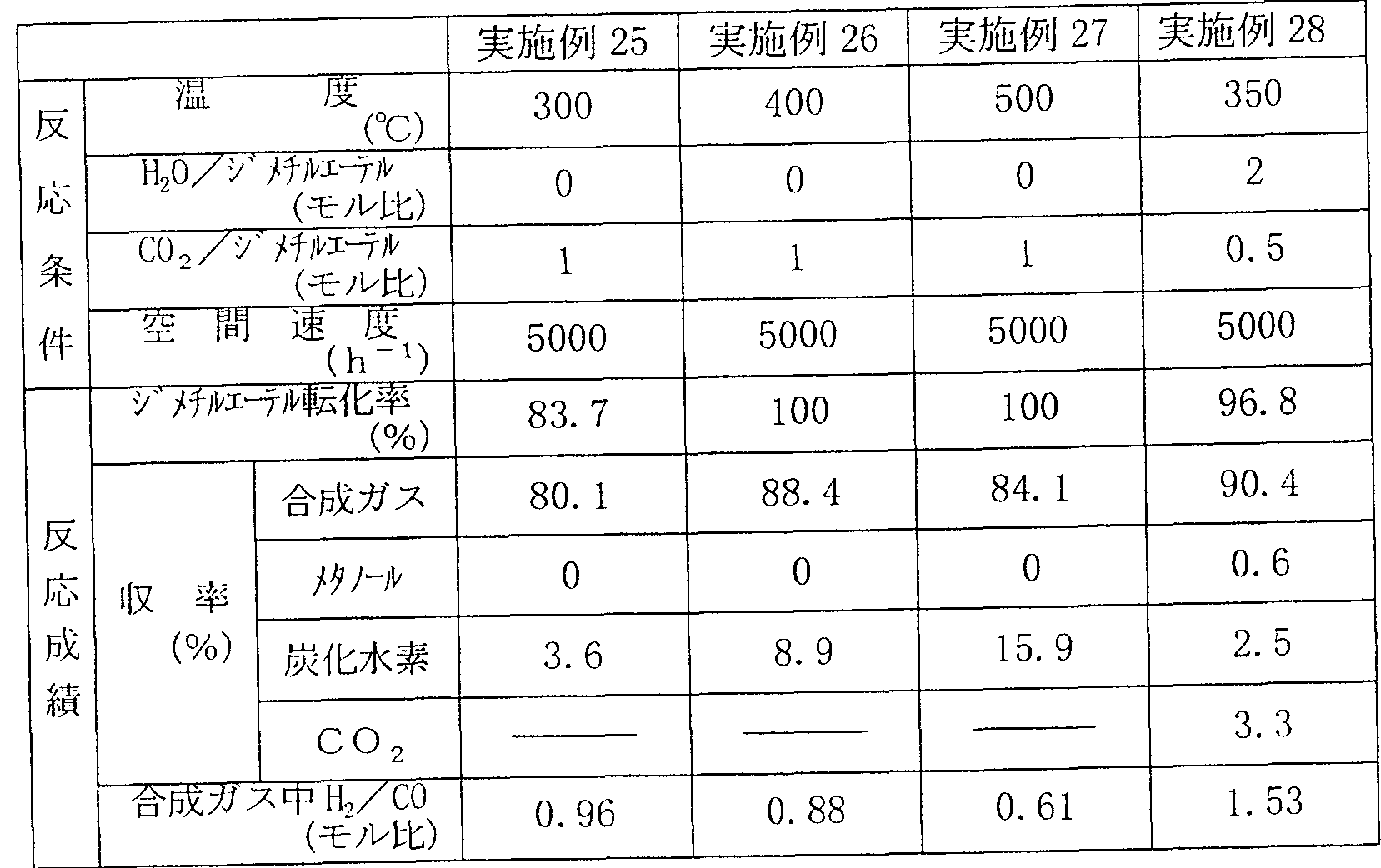
反応条件および実験結果を表 2 , 3に示す。 Tables 2 and 3 show the reaction conditions and experimental results.
1/6 X (。〇生成速度+ ^^生成速度) 1/6 X (.〇 generation speed + ^^ generation speed)
合成ガス収率(%)= X100 Synthesis gas yield (%) = X100
ジメチルエーテル供給速度
∑[n/2 X炭化水素 (炭素数 n )生成速度] 炭化水素収率(%) = X 100 ジメチルエーテル供給速度 Dimethyl ether feed rate ∑ [n / 2 X hydrocarbon (carbon number n) production rate] Hydrocarbon yield (%) = X 100 dimethyl ether feed rate
各速度の単位は全て [molZg— cat . h]
All units of each speed are [molZg—cat.h]
表 2 Table 2
実施例 1 実施例 2 実施例 3 実施例 4 触 媒 Example 1 Example 2 Example 3 Example 4 Catalyst
C u O-Z n O-A 12O3(30: 20: 50)C u OZ n OA 1 2 O 3 (30:20:50)
(重量比) (Weight ratio)
温 度 Temperature
250 300 350 300 250 300 350 300
(°C) (° C)
条 Article
CC^Zジメチノレエーテノレ CC ^ Z Dimethinoleatenole
1 1 1 2 1 1 1 2
(モル比) (Molar ratio)
件 Cases
空 問 速 度 Air speed
5000 5000 5000 3000 5000 5000 5000 3000
(h"1) (h " 1 )
ジメチル: —テル転化率 Dimethyl: —Tel conversion
74.8 78.2 83.1 85.5 74.8 78.2 83.1 85.5
(%) (%)
合 成 ガ ス 74.1 76.0 79.8 85.1 収 率 Synthetic gas 74.1 76.0 79.8 85.1 Yield
(%) (%)
炭 化 水 素 0.7 2.2 3.7 0.4 合成ガス中 H2ZCO Hydrocarbon 0.7 2.2 3.7 0.4 H 2 ZCO in synthesis gas
0.98 0.92 0.86 0.72 0.98 0.92 0.86 0.72
(モル比) (Molar ratio)
実施例 5 実施例 6 実施例 7 実施例 8 触 媒 Example 5 Example 6 Example 7 Example 8 Catalyst
C u〇- Z n O-A 12O3(30: 20: 50)C u〇-Zn OA 1 2 O 3 (30:20:50)
(重量比) (Weight ratio)
温 度 Temperature
250 300 350 300 250 300 350 300
(。C) (.C)
条 Article
c o 2Zジメチノレエーテノレ co 2 Z Dimethinoleatenore
1 1 1 2 (モル比) 1 1 1 2 (molar ratio)
件 Cases
空 間 速 度 Space speed
5000 5000 5000 3000 5000 5000 5000 3000
(h-1) (h- 1 )
ジメチルェ一テル転化率 Dimethyl ether conversion
69.3 73.5 77.4 80.7 69.3 73.5 77.4 80.7
(%) (%)
反 Anti
合 成 ガ ス 69.0 72.1 75.6 80.6 応 収 率 Synthetic gas 69.0 72.1 75.6 80.6 Yield
成 (%) (%)
炭 化 水 素 0.3 1.4 1.8 0.1 績 Carbohydrate 0.3 1.4 1.8 0.1
合成ガス中 H2ZCO H 2 ZCO in synthesis gas
0.99 0.95 0.91 0.89 0.99 0.95 0.91 0.89
(モル比)
実施例 9〜11 (Molar ratio) Examples 9 to 11
硝酸銅 (Cu (N03)2 · 3 H20) 91 g、 硝酸ニッケル (N i (N03) 2 · 6 H2〇) 39g、 硝酸亜鉛 (Z n (N03)2 · 6 Η2θ) 37 gおよび硝酸アルミニゥ ム (A 1 (N03)3 · 9H20) 368 gをイオン交換水約 2 1に溶解した水溶液と、 水酸化ナトリウム約 200 gをィオン交換水約 2 1に溶解した水溶液とを、 約 60°C に保温したイオン交換水約 5 1の入ったステンレス製容器中に、 pHが 8·0±0.5 に保持されるように調節しながら、 約 1時間かけて滴下した。 滴下終了後、 その まま約 1時間保持して熟成を行った。 なお、 この間に pHが 8.0±0.5 から外れ るようであれば、 約 1 molZ 1の硝酸水溶液または約 1 mol/ 1の水酸化ナトリウ ム水溶液を滴下して、 pHを 8.0±0.5 にあわせた。 次に、 生成した沈澱を濾過 した後、 洗浄液に硝酸ィオンが検出されなくなるまでィオン交換水を用いて洗浄 した。 得られたケーキを 120°Cで 24 時間乾燥した後、 さらに空気中 350°Cで 5 時間焼成した。 さらにこのものを 20〜40メッシュに分級して目的の触媒を得た。 得られた触媒の組成は C u O : N i O : Z n O : A 1 2O3 = 30: 10: 10: 50 (重量比) であった。 91 g of copper nitrate (Cu (N0 3 ) 2 · 3 H 2 0), 39 g of nickel nitrate (N i (N0 3 ) 2 · 6 H 2 〇), zinc nitrate (Zn (N0 3 ) 2 · 6 Η 2 θ) 37 g and aluminum nitrate (A 1 (N0 3 ) 3 · 9H 20 ) 368 g dissolved in about 21 deionized water, and about 200 g of sodium hydroxide in about 21 deionized water Take the dissolved aqueous solution in a stainless steel container containing about 51 ion-exchanged water kept at about 60 ° C, and adjust it so that the pH is kept at 8.0 ± 0.5, taking about 1 hour. It was dropped. After the completion of the dropwise addition, the mixture was kept for about 1 hour and aged. If the pH deviates from 8.0 ± 0.5 during this period, an aqueous solution of about 1 mol Z1 of nitric acid or an aqueous solution of about 1 mol / 1 of sodium hydroxide was added dropwise to adjust the pH to 8.0 ± 0.5. Next, the resulting precipitate was filtered and washed with ion-exchanged water until no ion was detected in the washing solution. The obtained cake was dried at 120 ° C for 24 hours, and then baked at 350 ° C for 5 hours in the air. This was further classified into 20 to 40 mesh to obtain the desired catalyst. The composition of the obtained catalysts C u O: N i O: Z n O: A 1 2 O 3 = 30: 10: 10: was 50 (weight ratio).
実施例 12 Example 12
実施例 9〜11の方法において、 硝酸二ッケルの代わりに硝酸クロム (C r (N 03) 2 · 3Η2θ) 53gを用いる以外、 実施例 9〜11 と同じ方法により触媒を調 製した。 In the method of Examples 9-11, except using nitrate dinitrate chromium instead of nickel (C r (N 0 3) 2 · 3Η 2 θ) 53g, it was manufactured by adjusting the catalyst in the same manner as in Example 9-11 .
得られた触媒の組成は C uO : C r 2Os : Z nO : A l 2O3 = 30: 10: 10: 50The composition of the resulting catalyst C uO: C r 2 O s : Z nO: A l 2 O 3 = 30: 10: 10: 50
(重量比) であった。 (Weight ratio).
実施例 13 Example 13
実施例 9〜11. の方法において、 硝酸ニッケルの代わりに硝酸マンガン (Mn (Ν03) 2 · 6 H20) 33gを用いる以外、 実施例 9〜11 と同じ方法により触媒 を調製した。
得られた触媒の糸且成は C u O : M n O 2 : Z n O: A 1 2 O 3 =30: 10: 10: 50In Examples 9-11. Manner, but using manganese nitrate (Mn (Ν0 3) 2 · 6 H 2 0) 33g instead of nickel nitrate, a catalyst was prepared by the same method as in Example 9-11. Yarn且成of the resulting catalyst C u O: M n O 2 : Z n O: A 1 2 O 3 = 30: 10: 10: 50
(重量比) であった。 (Weight ratio).
実施例 14 Example 14
実施例 13の方法において、 硝酸亜鉛の代わりに硝酸クロム (C r (N03) 2 · 3 H 2 O) 53 gを用いる以外、 実施例 9〜 11と同じ方法により触媒を調製した。 得られた触媒の糸且成は C u O : C r 2 O 3: M n O 2 : A 1 2 O 3 =30: 10: 10: 50 (重量比) であった。 In the method of Example 13, except using chromium nitrate (C r (N0 3) 2 · 3 H 2 O) 53 g instead of zinc nitrate, a catalyst was prepared by the same method as in Example 9-11. Yarn且成of the resulting catalyst C u O: C r 2 O 3: M n O 2: A 1 2 O 3 = 30: 10: 10: was 50 (weight ratio).
反応方法 Reaction method
内径 20 のステンレス製反応管に所定量の上記触媒を充填した。 この反応管 にジメチルエーテルと水蒸気を所定量供給して、 所定の温度で反応させた。 A predetermined amount of the above catalyst was filled in a stainless steel reaction tube having an inner diameter of 20. A predetermined amount of dimethyl ether and water vapor were supplied to the reaction tube and reacted at a predetermined temperature.
以上の操作により得られた反応生成物および未反応物はガスクロマ卜グラフに より分析した。 The reaction products and unreacted products obtained by the above operations were analyzed by gas chromatography.
反応条件および実験結果 Reaction conditions and experimental results
反応条件および実験結果を表 4, 5に示す。 Tables 4 and 5 show the reaction conditions and experimental results.
1 X (H2生成速度一 2 X CO生成速度) 1 X (H 2 generation rate-2 X CO generation rate)
+ +
1/4 X CO生成速度 1/4 X CO generation rate
水素収率(%) ■X 100 Hydrogen yield (%) ■ X 100
ジメチルェ一テル供給速度 Dimethyl ether feed rate
X -ル生成速度 X-rule generation speed
メタノール収率(%) = X100 Methanol yield (%) = X100
ジメチルエーテル供給速度 Dimethyl ether feed rate
1/4 X CO生成速度 1/4 X CO generation rate
CO収率(%) = X100 CO yield (%) = X100
ジメチルエーテル供給速度 Dimethyl ether feed rate
各速度の単位は全て [mol/g— cat · h]
表 4 All units of each speed are [mol / g—cat · h] Table 4
実施例 9 実施例 10 実施例 11 媒 CuO-ZnO-AL03 CuO-ZnO-AL03 CuO- ΖηΟ - Α1203 Example 9 Example 10 Example 11 medium CuO-ZnO-AL0 3 CuO- ZnO-AL0 3 CuO- ΖηΟ - Α1 2 0 3
(重量比) (30:10:10:50) (30:10:10:50) (30:10:10:50) 曰 (Weight ratio) (30: 10: 10: 50) (30: 10: 10: 50) (30: 10: 10: 50)
度 Every time
200 250 300 200 250 300
(°C) (° C)
条、 Article,
co2Zシ、'メチルエーテル co 2 Z, 'methyl ether
10 10 10 10 10 10
(モル比) (Molar ratio)
件 Cases
空 間 速 度 Space speed
15000 15000 15000 (h一1) 15000 15000 15000 (h- 1 )
シ"メチルエ-テル転化率 Conversion of methyl ether
83.3 98.1 100 (%) 83.3 98.1 100 (%)
反 Anti
水素 79.2 92.0 88. δ 応 Hydrogen 79.2 92.0 88.δ
成 収 率 メタノ-ル 2.5 3.8 6.2 Yield Methanol 2.5 3.8 6.2
(%) 炭化水素 0.1 0.1 0.3 (%) Hydrocarbon 0.1 0.1 0.3
CO 1.5 2.2 4.9 CO 1.5 2.2 4.9
実施例 12 実施例 13 実施例 14 触 媒 Cu0-Zn0-Al203 CuO - ΖηΟ- Α1203 CuO- ΖηΟ- Α1203 Example 12 Example 13 Example 14 catalysts Cu0-Zn0-Al 2 0 3 CuO - ΖηΟ- Α1 2 0 3 CuO- ΖηΟ- Α1 2 0 3
(重量比) (30:10:10:50) (30:10:10:50) (30:10:10:50) 曰 度 (Weight ratio) (30: 10: 10: 50) (30: 10: 10: 50) (30: 10: 10: 50)
250 250 250 250 250 250
(。c) (.C)
条 Article
C02/v"メチルエーテル C0 2 / v "methyl ether
10 10 10 10 10 10
(モル比) (Molar ratio)
件 Cases
空 問 速 度 Air speed
15000 15000 15000 (h一1) 15000 15000 15000 (h- 1 )
シ、'メチルエーテル舉云ィ匕 Shi, 'Methyl ether
94.3 92.2 91.8 (%) 94.3 92.2 91.8 (%)
反 Anti
水素 86.4 85.1 84.6 'し、 Hydrogen 86.4 85.1 84.6 '
成 収 率 メタノ-ル 4.3 4.1 3.8 績 (%) 炭化水素 0.1 0.1 0.1 Yield Methanol 4.3 4.1 3.8 Performance (%) Hydrocarbon 0.1 0.1 0.1
CO 3. δ 2.9 3.3
実施例 15〜17 CO 3.δ 2.9 3.3 Examples 15 to 17
硝酸鉄 (F e (N03)3 · 9H2〇) 405 g、 硝酸クロム (C r (N03) 2 · 3 H2 O) 79 g、 および硝酸アルミニウム (A 1 (N〇3) 3 · 9 H 20 ) 37 gをイオン交 換水約 2 1に溶解した水溶液と、 水酸ィヒナ卜リウム約 180 gをイオン交換水約 2 Iに溶解した水溶液とを、 約 80=Cに保温したイオン交換水約 5 1の入ったステ ンレス製容器中に、 pHが 8.0±0.5 に保持されるように調節しながら、 約 1時 間かけて滴下した。 滴下終了後、そのまま約 1時間保持して熟成を行った。 なお、 この問に p Hが 8.0±0.5 から外れるようであれば、 約 1 molZ 1の硝酸水溶液 または約 1 molZ 1の水酸化ナトリゥム水溶液を滴下して、 p Hを 8.0± 0. 5 にあわせた。 次に、 生成した沈澱を濾過した後、 洗浄液に硝酸イオンが検出され なくなるまでイオン交換水を用いて洗浄した。 得られたケーキを 120eCで 24時 間乾燥した後、 さらに空気中 350°Cで 5時問焼成した。 さらにこのものを 20〜40 メッシュに分級して目的の触媒を得た。 405 g of iron nitrate (F e (N0 3 ) 3 · 9H 2 〇), 79 g of chromium nitrate (C r (N 0 3 ) 2 · 3 H 2 O), and aluminum nitrate (A 1 (N〇 3 ) 3 · 9 H 2 0) and an aqueous solution of 37 g were dissolved in ion-exchanged water to about 2 1, and an aqueous solution of hydroxyl Ihina Bok potassium about 180 g of ion-exchanged water to about 2 I, kept at about 80 = C ions The solution was dropped into a stainless steel container containing about 51 exchanged water over about 1 hour while adjusting the pH to be maintained at 8.0 ± 0.5. After completion of the dropping, the mixture was kept for about 1 hour to ripen. If the pH deviates from 8.0 ± 0.5 in this question, add about 1 molZ1 aqueous nitric acid solution or about 1 molZ1 sodium hydroxide aqueous solution dropwise and adjust the pH to 8.0 ± 0.5. Was. Next, the resulting precipitate was filtered and washed with ion-exchanged water until no nitrate ion was detected in the washing solution. After the resulting cake was dried for 24 hours at 120 e C and was further 5 more hours calcination at 350 ° C in air. This was further classified to 20 to 40 mesh to obtain the desired catalyst.
得られた触媒の組成は F e 2〇3: C r 203: A 12O3=80: 15: 5 (重量比) であった。 The composition of the resulting catalyst F e 2 〇 3: C r 2 0 3: A 1 2 O 3 = 80: 15: was 5 (weight ratio).
実施例 18〜20 Examples 18 to 20
実施例 〜 17の方法において、 硝酸ク口ムの代わりに硝酸亜鉛 In the method of Examples 17-17, zinc nitrate was used instead of potassium nitrate.
(Z n (N03) 2 · 6 H20) 55 gを用いる以外、 実施例 15〜17 と同じ方法によ り触媒を調製した。 (Z n (N0 3) 2 · 6 H 2 0) except for using 55 g, to prepare a catalyst Ri by the same method as in Example 15 to 17.
得られた触媒の組成は F e 203: Z n O: A 1 2O3=80: 15: 5 (重量比) であった。 The composition of the resulting catalyst F e 2 0 3: Z n O: A 1 2 O 3 = 80: 15: was 5 (weight ratio).
反応方法 Reaction method
内径 20mmのステンレス製反応管に所定量の上記触媒を充填した。 この反応 管にジメチルエーテルと水蒸気を所定量供給して、 所定の温度で反応させた。 以上の操作により得られた反応生成物および未反応物はガスクロマ
より分析した。 A predetermined amount of the above catalyst was filled in a stainless steel reaction tube having an inner diameter of 20 mm. A predetermined amount of dimethyl ether and water vapor were supplied to the reaction tube and reacted at a predetermined temperature. The reaction products and unreacted products obtained by the above operation are More analyzed.
反応条件および実験結果 Reaction conditions and experimental results
反応条件および実験結果を表 6, 7に示す
Tables 6 and 7 show the reaction conditions and experimental results.
表 6 Table 6
実施例 15 実施例 16 実施例 17 触 媒 F e , O 3 - C r 03-A 1 O, Example 15 Example 16 Example 17 catalysts F e, O 3 - C r 0 3 -A 1 O,
(重量比) (Weight ratio)
曰 度 Say
OU Ann OU Ann
CO CO
条 Article
C02/シ"メチルエーテル C0 2 / Shi "ether
10 10 10 10 10 10
(モル比) (Molar ratio)
件 Cases
空 間 速 度 Space speed
25000 25000 25000 (h"1) 25000 25000 25000 (h " 1 )
シ"メチルエ-テル転化率 Conversion of methyl ether
93.7 100 100 93.7 100 100
(%) (%)
反 Anti
水素 91.9 95.8 93.6 応 Hydrogen 91.9 95.8 93.6
成 収 率 メタノール 0.1 0.1 0.2 績 (%) 炭化水素 0.2 0.9 1.9 Yield rate Methanol 0.1 0.1 0.2 Performance (%) Hydrocarbon 0.2 0.9 1.9
CO 1. δ 3.2 4.3 CO 1.δ 3.2 4.3
実施例 18 実施例 19 実施例 20 触 媒 F e : 03-Z n O-A i 2o3 Example 18 Example 19 Example 20 Catalyst F e : 0 3 -Zn OA i 2 o 3
(重量比) (80:15: 5) 曰 度 (Weight ratio) (80: 15: 5)
300 350 400 300 350 400
(。c) (.C)
条 Article
C02/ "メチルエーテル C0 2 / "methyl ether
10 10 10 10 10 10
(モル比) (Molar ratio)
件 Cases
空 間 速 度 Space speed
25000 25000 25000 (h一1) 25000 25000 25000 (h- 1 )
シ"メチルエ-テル転化率 Conversion of methyl ether
89.1 100 100 (%) 89.1 100 100 (%)
反 Anti
水素 87.6 94.0 92.1 し、 Hydrogen 87.6 94.0 92.1
成 メタノ-ル Methanol
収 率 0.1 0.1 0.1 m (%) 炭化水素 0.1 1.3 1.1 Yield 0.1 0.1 0.1 m (%) Hydrocarbon 0.1 1.3 1.1
CO 1.3 4.6 6.7
実施例 2ト 28 CO 1.3 4.6 6.7 Example 2
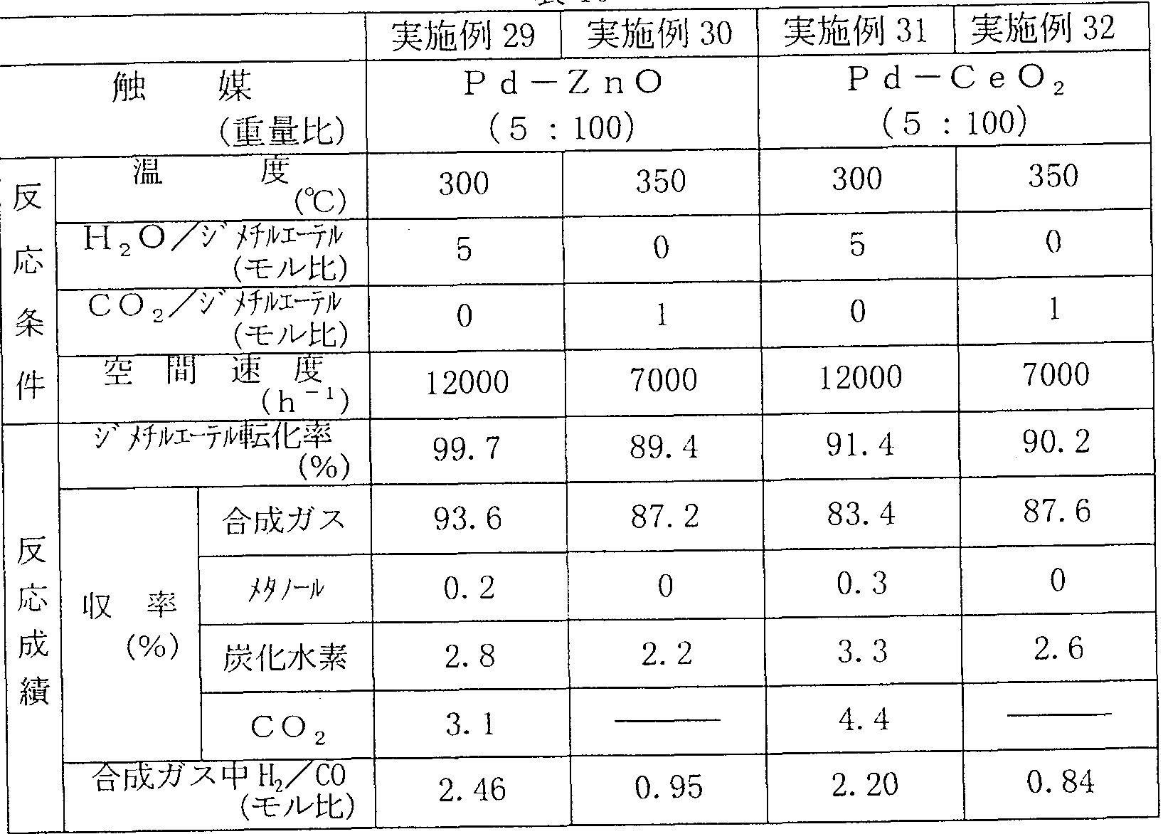
酢酸コバルト (C o (NO 3)2 · 6 H20) 49.4 gをイオン交換水約 300 ml に 溶解させ、 さらにこの水溶液に γ—アルミナ (日揮化学製、 N612) 90gを投入 し、 蒸発乾固した。 そして、 このものを空気中、 120°Cで 24 時間乾燥し、 さら に空気中、 500°Cで 3時問焼成した。 ついで水素気流中、 500°Cで 3時間処理を 行って触媒を得た。 Cobalt acetate (C o (NO 3) 2 · 6 H 2 0) 49.4 g is dissolved in about 300 ml deionized water, further to the aqueous solution γ- alumina (Nikki Chemical Co., N612) 90 g were charged, evaporated to dryness Hardened. This was dried in air at 120 ° C. for 24 hours, and further baked in air at 500 ° C. for 3 hours. Then, the catalyst was treated at 500 ° C for 3 hours in a hydrogen stream to obtain a catalyst.
得られた触媒の組成は、 C o : A 1 2O3 = 10: 90 (重量比) であった。 The composition of the obtained catalysts, C o: A 1 2 O 3 = 10: was 90 (weight ratio).
反応方法 Reaction method
内径 20 画のステンレス製反応管に所定量の上記触媒を充填した。 この反応管 にジメチルェ一テルと水蒸気および Zまたは二酸化炭素を所定量供給して、 所定 の温度で反応させた。 A predetermined amount of the above catalyst was filled in a stainless steel reaction tube having an inner diameter of 20 strokes. Dimethyl ether, water vapor and Z or carbon dioxide were supplied in a predetermined amount to the reaction tube, and reacted at a predetermined temperature.
以上の操作により得られた反応生成物および未反応物はガスクロマグラフによ り分析した。 The reaction products and unreacted products obtained by the above operations were analyzed by gas chromatography.
反応条件および実験結果 Reaction conditions and experimental results
反応条件および実験結果を表 8 , 9に示す。 Tables 8 and 9 show the reaction conditions and experimental results.
1 / 2 XCO,生成速度 1/2 XCO, generation rate
C O ?収率(%) = X 100 CO ? Yield (%) = X 100
ェ一テル供給速度 各速度の単位は全て [molZg— cat . h]
Ether feed rate All units for each feed rate are [molZg—cat.h]
表 9
実施例 29, 30 Table 9 Examples 29, 30
塩酸 6ml および塩化パラジウム (P d C 12) 8.33 gをイオン交換水約 500ml に溶解させた水溶液に、 酸化亜鉛 (関東化学製, 試薬特級) l()0gを投入して、 蒸発乾固した。 これを、 空気中 120°Cで 24時問乾燥し、 さらに空気中、 500°Cで 3時問焼成した。 ついで、 このものを水酸化ナトリウム 10gをイオン交換水約 1000ml に溶解した水溶液中に投入し、 50°Cに加熱して、 約 1時間の処理を行つ た後、 塩素イオンが検出されなくなるまで洗浄し、 120°Cで 24 時間乾燥した。 さらに、 このものを圧縮成型により、 20〜40 メッシュに整粒した後、 水素気流 中、 500°Cで 3時間処理を行って触媒を得た。 Hydrochloride 6ml and palladium chloride (P d C 1 2) 8.33 g in an aqueous solution dissolved in deionized water to about 500 ml, zinc oxide (Kanto Chemical, special grade reagent) l () was charged to 0 g, and evaporated to dryness . This was dried in air at 120 ° C for 24 hours, and then fired in air at 500 ° C for 3 hours. Then, this is poured into an aqueous solution of 10 g of sodium hydroxide dissolved in about 1000 ml of ion-exchanged water, heated to 50 ° C and treated for about 1 hour, until chlorine ions are no longer detected It was washed and dried at 120 ° C for 24 hours. Furthermore, this was sized by compression molding to 20 to 40 mesh, and then treated in a hydrogen stream at 500 ° C for 3 hours to obtain a catalyst.
得られた触媒の組成は、 P d : Z nO=5 : 100 (重量比) であった。 The composition of the obtained catalyst was Pd: ZnO = 5: 100 (weight ratio).
実施例 31, 32 Examples 31 and 32
実施例 29, 30 の方法において、 酸化亜鉛の代わりに酸化セリウム (関東化学 製, 試薬特級) を用いる以外、 実施例 29, 30と同じ方法により触媒を調製した。 得られた触媒の組成は、 P d : C e〇2= 5 : 100 (重量比) であった。 Catalysts were prepared in the same manner as in Examples 29 and 30, except that cerium oxide (manufactured by Kanto Chemical Co., Ltd., reagent grade) was used instead of zinc oxide. The composition of the obtained catalysts, P d: C E_〇 2 = 5: was 100 (weight ratio).
実施例 33, 34 Examples 33 and 34
塩酸 6 mlおよび塩化パラジゥム ( P d C 12 ) 8.33 gをィオン交換水約 500tnl に溶解させた水溶液に、 y—アルミナ (日揮化学製, N6 1 2) 100gを投入し て、 蒸発乾固した後、 空気中 120°Cで 24時間乾燥し、 さらに空気中、 500°Cで 3 時間焼成した。ついでこのものを水酸化ナトリウム 50gをイオン交換水約 1000ml に溶解した水溶液中に投入し、 50°Cに加熱して、 約 1時問の処理を行った後、 洗浄を行うことなく、 分離したのみで乾燥した。 さらにこのものを圧縮成型によ り、 20〜40 メッシュに整粒した後、 水素気流中、 500°Cで 3時間処理を行って触 媒を得た。 Hydrochloride 6 ml and chloride Parajiumu a (P d C 1 2) 8.33 g in an aqueous solution dissolved in Ion-exchanged water to about 500tnl, y- alumina (Nikki Chemical Co., N6 1 2) was charged with 100 g, and evaporated to dryness After that, it was dried in air at 120 ° C for 24 hours, and further baked in air at 500 ° C for 3 hours. Then, this was put into an aqueous solution in which 50 g of sodium hydroxide was dissolved in about 1000 ml of ion-exchanged water, heated to 50 ° C, and treated for about 1 hour, and then separated without washing. Only dried. The powder was sized to 20 to 40 mesh by compression molding, and then treated in a hydrogen stream at 500 ° C for 3 hours to obtain a catalyst.
得られた触媒の組成は、 Pd : Na 2〇 : A l 2O3 = 5 : 0.4 : 100 (重量比) であった。
実施例 35, 36 The composition of the obtained catalyst was Pd: Na 2 :: Al 2 O 3 = 5: 0.4: 100 (weight ratio). Examples 35 and 36
塩酸 6 ml および塩化パラジウム (P d C 1 2 ) 8. 33 gをイオン交換水約 500ml に溶解させた水溶液に、 シリカゲル (富士ディヴィソン化学, I D ) 100 gを投 入して、 蒸発乾固した。 これを、 空気中 120°Cで 24時間乾燥し、 さらに空気中、 500°Cで 3時間焼成した。 ついで、 このものを水酸化カルシウム 10 gをイオン交 換水約 1000ml に溶解した水溶液中に投入し、 50°Cに加熱して、 約 1時間の処理 を行った後、 洗浄、 乾燥を行った。 さらにこのもの約 80 gを、 水酸化カルシゥ ム 6. 6 gをィオン交換水約 200ml に溶解した水溶液に投入し、 蒸発乾固した後、 乾燥した。 このものを圧縮成型により、 20〜40 メッシュに整粒した後、 水素気 流中、 500QCで 3時間処理を行つて触媒を得た。 Hydrochloride 6 ml and palladium chloride (P d C 1 2) 8. 33 g in an aqueous solution dissolved in deionized water to about 500 ml, silica gel (Fuji Divison Chemical, ID) with the 100 g and projecting ON, and evaporated to dryness . This was dried in air at 120 ° C. for 24 hours, and further baked in air at 500 ° C. for 3 hours. Then, this was poured into an aqueous solution in which 10 g of calcium hydroxide was dissolved in about 1000 ml of ion-exchanged water, heated to 50 ° C., and treated for about 1 hour, followed by washing and drying. Further, about 80 g of this was poured into an aqueous solution obtained by dissolving 6.6 g of calcium hydroxide in about 200 ml of ion-exchanged water, evaporated to dryness, and dried. This was sized by compression molding to 20 to 40 mesh, and then treated in a hydrogen stream at 500 QC for 3 hours to obtain a catalyst.
得られた触媒の組成は、 P d : C a O : S i 0 2 = 5 : 5 : 100 (重量比) で あった。 The composition of the obtained catalysts, P d: C a O: S i 0 2 = 5: 5: was 100 (weight ratio).
反応方法 Reaction method
内径 20闘 のステンレス製反応管に所定量の上記触媒を充填した。 この反応管 にジメチルエーテルと水蒸気および Zまたは二酸化炭素を所定量供給して、 所定 の温度で反応させた。 A predetermined amount of the above catalyst was filled in a stainless steel reaction tube having an inner diameter of 20 mm. A predetermined amount of dimethyl ether, steam and Z or carbon dioxide were supplied to the reaction tube, and reacted at a predetermined temperature.
以上の操作により得られた反応生成物および未反応物はガスクロマトグラフに より分析した。 The reaction products and unreacted products obtained by the above operations were analyzed by gas chromatography.
反応条件および実験結果 Reaction conditions and experimental results
反応条件および実験結果を表 10, 11に示す。
表 10
Tables 10 and 11 show the reaction conditions and experimental results. Table 10
表 11
実施例 37 42 Table 11 Example 37 42
塩化ィリジゥム ( I r C 1 3) 0.777 gをイオン交換水約 300ml に溶解させ、 さらにこの水溶液に γ—アルミナ (触媒学会, ALO— 4) 99.5 gを投入し、 蒸発乾固した。 そして、 このものを空気中、 120°Cで 24 時間乾燥し、 さらに空 気中、 500°Cで 3時間焼成した。 ついで水素気流中、 500°Cで 3時問処理を行つ て触媒を得た。 The Irijiumu chloride (I r C 1 3) 0.777 g was dissolved in deionized water to about 300 ml, further to the aqueous solution γ- alumina (Catalysis Society, ALO- 4) 99.5 g were charged, and evaporated to dryness. Then, this was dried in air at 120 ° C for 24 hours, and further baked in air at 500 ° C for 3 hours. Subsequently, the catalyst was treated at 500 ° C for 3 hours in a hydrogen stream to obtain a catalyst.
得られた触媒の組成は、 I r : A 1 2O3==0.5: 99.5 (重量比) であった。 反応方法 The composition of the obtained catalyst, I r: A 1 2 O 3 == 0.5: was 99.5 (weight ratio). Reaction method
内径 20 のステンレス製反応管に所定量の上記触媒を充填した。 この反応管 にジメチルエーテルと水蒸気を所定量供給して、 所定の温度で反応させた。 以上の操作により得られた反応生成物および未反応物はガスクロマトグラフに より分析した。 A predetermined amount of the above catalyst was filled in a stainless steel reaction tube having an inner diameter of 20. A predetermined amount of dimethyl ether and water vapor were supplied to the reaction tube and reacted at a predetermined temperature. The reaction products and unreacted products obtained by the above operations were analyzed by gas chromatography.
反応条件および実験結果 Reaction conditions and experimental results
反応条件および実験結果を表 12, 13に示す。
Tables 12 and 13 show the reaction conditions and experimental results.
表 12 Table 12
実施例 40 実施例 41 実施例 42 触 媒 I r -A 1 203 Example 40 Example 41 Example 42 Catalyst I r -A 1 2 0 3
(重量比) (0. 5: 99. 5) (Weight ratio) (0.5: 99.5)
ΐπιι. 度 ΐπιι. degree
450 450 450 450 450 450
(°C) (° C)
条 Article
Ηつ〇ノ 'ズメチルエーテル Petzno's methyl ether
3 5 10 3 5 10
(モル比) (Molar ratio)
件 Cases
空 間 速 度 Space speed
10000 10000 10000 ( h一1 ) 10000 10000 10000 (h- 1 )
メチルエ-テル転ィ匕率 Methyl ether conversion ratio
98. 0 97. 3 99. 5 (%) 98.0 97.3 99.5 (%)
反 Anti
合成ガス 83. 2 89. 5 95. 6 し、 Synthesis gas 83.2 89.5 95.6
成 収 率 メタノール 1. 1 0. 3 0. 2 貝 (%) 炭化水素 13. 7 7. 5 3. 7 c o 2 0 0 0
実施例 43 48 Yield Methanol 1.10 0.3 0.2 Shellfish (%) Hydrocarbons 13.7 7.5 3.3.7 co 2 0 0 0 Example 43 48
塩化白金 (P t C 1 J 0.863gを 10 %の塩酸水溶液約 300ml に溶解させ、 さらにこの水溶液に γ—アルミナ (触媒学会, ALO— 4) 99.5 gを投入し、 蒸発乾固した。 そして、 このものを空気中、 120°Cで 24 時間乾燥し、 さらに空 気中、 500°Cで 3時間焼成した。 ついで水素気流中、 500°Cで 3時間処理を行つ て触媒を得た。 0.863 g of platinum chloride (PtC1J) was dissolved in about 300 ml of a 10% hydrochloric acid aqueous solution, and 99.5 g of γ-alumina (Catalyst Society of Japan, ALO-4) was added to the aqueous solution and evaporated to dryness. This was dried in air at 120 ° C. for 24 hours, and calcined in air at 500 ° C. for 3 hours, and then treated in a hydrogen stream at 500 ° C. for 3 hours to obtain a catalyst.
得られた触媒の組成は、 P t : A 1 2Ο3=0. δ: 99.5 (重量比) であった。 反応方法 The composition of the obtained catalysts, P t: A 1 2 Ο 3 = 0 δ:. Was 99.5 (weight ratio). Reaction method
内径 20 のステンレス製反応管に所定量の上記触媒を充填した。 この反応管 にジメチルュ一テルと水蒸気を所定量供給して、 所定の温度で反応させた。 以上の操作により得られた反応生成物および未反応物はガスクロマトグラフに より分析した。 A predetermined amount of the above catalyst was filled in a stainless steel reaction tube having an inner diameter of 20. A predetermined amount of dimethyl ether and water vapor were supplied to the reaction tube and reacted at a predetermined temperature. The reaction products and unreacted products obtained by the above operations were analyzed by gas chromatography.
反応条件および実験結果 Reaction conditions and experimental results
反応条件および実験結果を表 14, 15に示す。
Tables 14 and 15 show the reaction conditions and experimental results.
表 14 Table 14
実施例 43 実施例 44 実施例 45 触 媒 P t - A 12〇3 Example 43 Example 44 Example 45 Catalyst Pt-A 1 2 〇 3
(重量比) (0.5: 99.5) (Weight ratio) (0.5: 99.5)
V曰 度 V says
300 350 400 300 350 400
(°C) (° C)
条 Article
Η2θΖシ "メチルエーテル Η 2 θΖ "Methyl ether
1 1 1 1 1 1
(モル比) (Molar ratio)
件 Cases
空 問 速 度 Air speed
10000 10000 10000 (h-1) 10000 10000 10000 (h- 1 )
シ"メチルエーテル転化率 Methyl ether conversion
21.6 40.2 98.0 (%) 21.6 40.2 98.0 (%)
反 Anti
合成ガス 7.1 19.3 52.9 応 Syngas 7.1 19.3 52.9
成 収 率 メタノ-ル 9.3 11.7 4δ.1 績 (%) 炭化水素 2.2 12.5 0 co2 3.0 0 0 表 15 Yield Methanol 9.3 11.7 4δ.1 Performance (%) Hydrocarbon 2.2 12.5 0 co 2 3.0 0 0 Table 15
実施例 46 実施例 47 実施例 48 触 媒 P t-A 12〇3 Example 46 Example 47 Example 48 Catalyst PtA 1 2 〇 3
(重量比) (0. δ: 99.5) y曰 (Weight ratio) (0. δ: 99.5)
tun. 度 tun. degree
400 400 400 400 400 400
(°C) (° C)
条 Article
H2〇Zyメチルエ-テル H 2 〇Zy methyl ether
3 5 10 3 5 10
(モル比) (Molar ratio)
件 Cases
空 間 速 度 Space speed
10000 10000 10000 (h一1) 10000 10000 10000 (h- 1 )
yメチルエ-テル転化率 y methyl ether conversion
96.6 95.9 97.6 (%) 96.6 95.9 97.6 (%)
反 Anti
合成ガス 74.1 79.4 83.6 成 収 率 メタノ-ル 18.7 11.4 4.3 績 (%) 炭化水素 0 0 0 co2 3.8 δ.1 9.7
実施例 49〜54 Syngas 74.1 79.4 83.6 Yield Methanol 18.7 11.4 4.3 Performance (%) Hydrocarbons 0 0 0 co 2 3.8 δ.1 9.7 Examples 49 to 54
硝酸ロジウム (Rh (N03) 1.40 gをイオン交換水約 300ml に溶解させ、 さ らにこの水溶液に ーアルミナ (触媒学会, ALO— 4) 99.5 gを投入し、 蒸 発乾固した。 そして、 このものを空気中、 120°Cで 24 時間乾燥し、 さらに空気 中、 500°Cで 3時間焼成した。 ついで水素気流中、 500°Cで 3時問処理を行って 触媒を得た。 Dissolved rhodium nitrate (Rh (N0 3) 1.40 g of ion-exchanged water to about 300 ml, is et to-alumina (Catalysis Society in this aqueous solution, ALO- 4) was charged 99.5 g, was solidified steam Hatsuinui. Then, this The product was dried in air at 120 ° C. for 24 hours, and calcined in air at 500 ° C. for 3 hours, and then treated in a hydrogen stream at 500 ° C. for 3 hours to obtain a catalyst.
得られた触媒の組成は、 Rh : A 12Ο3=0. δ: 99. δ (重量比) であった。 反応方法 The composition of the obtained catalysts, Rh: A 1 2 Ο 3 = 0 δ:. 99. was [delta] (weight ratio). Reaction method
内径 2ϋ隱 のステンレス製反応管に所定量の上記触媒を充填した。 この反応管 にジメチルエーテルと水蒸気を所定量供給して、 所定の温度で反応させた。 以上の操作により得られた反応生成物および未反応物はガスクロマトグラフに より分析した。 A predetermined amount of the above catalyst was filled in a stainless steel reaction tube having an inner diameter of 2 mm. A predetermined amount of dimethyl ether and water vapor were supplied to the reaction tube and reacted at a predetermined temperature. The reaction products and unreacted products obtained by the above operations were analyzed by gas chromatography.
反応条件および実験結果 Reaction conditions and experimental results
反応条件および実験結果を表 16, 17に示す。
Tables 16 and 17 show the reaction conditions and experimental results.
表 16 Table 16
実施例 49 実施例 50 実施例 51 媒 R h-A 1 0, Example 49 Example 50 Example 51 Medium R h-A 10
(重量比) (0.5: 99.5) (Weight ratio) (0.5: 99.5)
、曰 ,
度 Every time
350 400 450 350 400 450
(。 (.
条 c) Article c)
水 water
H20/v "メチルエーテル H 2 0 / v "methyl ether
1 1 1 1 1 1
(モル比) (Molar ratio)
件 Cases
空 間 速 度 Space speed
10000 10000 10000 (h"1) 10000 10000 10000 (h " 1 )
シ"メチルエ-テル転化率 Conversion of methyl ether
19.1 65.3 89.7 (%) 19.1 65.3 89.7 (%)
反 Anti
合成ガス 7.4 40.5 DO.0 応 Syngas 7.4 40.5 DO.
11.7 7.2 11.7 7.2
成 収 率 メタノ-ル 1.8 Yield Methanol 1.8
(%) 炭化水素 0 17.6 22.4 co2 0 0 0 (%) Hydrocarbons 0 17.6 22.4 co 2 0 0 0
実施例 52 実施例 53 実施例 54 媒 R h-A 1203 Example 52 Example 53 Example 54 Medium R hA 1 2 0 3
(重量比) (0. δ: 99.5) y曰 度 (Weight ratio) (0. δ: 99.5) y
400 400 400 400 400 400
(°C) (° C)
条 Article
Η2〇/シ "メチルエ テル Η 2 〇 / death "methyl ethyl ether
3 0 10 3 0 10
(モル比) (Molar ratio)
件 Cases
空 間 速 度 Space speed
10000 10000 10000 (h一1) 10000 10000 10000 (h- 1 )
シ-'メチルエ-テル転ィ匕率 Sea 'methyl ether
72.1 88.6 90.9 (%) 72.1 88.6 90.9 (%)
反 Anti
合成ガス 57.0 76.5 78.7 、 Synthesis gas 57.0 76.5 78.7,
成 収 率 メタノ-ル 3.1 1.3 0. δ 績 (%) 炭化水素 10. δ 7.0 2.8 co2 1.5 3.8 8.9
実施例 55〜56 Yield Methanol 3.1 1.3 0.δ results (%) Hydrocarbons 10.δ 7.0 2.8 co 2 1.5 3.8 8.9 Examples 55-56
塩酸 5ml に塩化パラジウム (P d C l 2) 0.833 gを溶解させ、 さらにこれに イオン交換水を加えて約 500mlとした水溶液に、 シリカゲル (触媒学会, S I〇 -4) 9£).5gを投入し、 蒸発乾固した。 そして、 このものを空気中、 120°Cで 24 時間乾燥し、 さらに空気中、 500°Cで 3時間焼成した。 ついで、 このものを 20〜 40 メッシュに整粒した後、 水素気流中、 500°Cで 3時間処理を行った。 このもの の組成は、 P d : A 1 2Ο3 = 0.5: 99.5 (重量比) であった。 さらに、 このもの と、' 20〜40 メッシュに整粒した y—アルミナ (触媒学会, ALO—4) とを、 重量比で 1 : 1に物理的に混合して触媒を得た。 Dissolving palladium chloride (P d C l 2) 0.833 g hydrochloric acid 5 ml, more aqueous solution with about 500ml by adding ion exchanged water thereto, silica gel (Catalysis Society, SI_〇 -4) to 9 £) .5G It was charged and evaporated to dryness. This was dried in air at 120 ° C for 24 hours, and further baked in air at 500 ° C for 3 hours. Then, this was sized to 20 to 40 mesh, and then treated at 500 ° C for 3 hours in a hydrogen stream. The composition of this product, P d: A 1 2 Ο 3 = 0.5: was 99.5 (weight ratio). Furthermore, a catalyst was obtained by physically mixing this with y-alumina (catalyst society, ALO-4) sized to 20 to 40 mesh at a weight ratio of 1: 1.
実施例 60〜64 Examples 60-64
塩酸 5 m 1 に塩化パラジウム (P d C l 2) 0.833gを溶解させ、 さらにこれ にイオン交換水を加えて約 500ml とした水溶液に、 シリカゲル (触媒学会, S I 0-4) 98· 5 gを投入し、 蒸発乾固した。 そして、 このものを空気中、 120°Cで 24 時間乾燥し、 さらに空気中、 500°Cで 3時問焼成した。 ついで、 このものを、Hydrochloride 5 m 1 palladium chloride (P d C l 2) 0.833g dissolved, further ion exchange water in an aqueous solution was about 500ml Additionally, silica gel (Catalysis Society, SI 0-4) 98 · 5 g And evaporated to dryness. Then, it was dried in air at 120 ° C for 24 hours and fired in air at 500 ° C for 3 hours. Then, this thing,
;勺 500ml のイオン交換水に炭酸カリウム (K。C〇3) L46gを溶解した水溶液 に投入して、 蒸発乾固した。 そして、 このものを空気中、 120°Cで 24時間乾燥 し、 さらに空気中 500°Cで 3時問焼成した。 さらに、 このものを 20〜40 メッシ ュに整粒した後、 水素気流中、 500°Cで 3時間処理を行った。 このものの組成は、 P d : K20 : A 1 2O3=0.5: 1.0: 98.5 (重量比) であった。 さらにまた、 こ のものと、 20〜40 メッシュに整粒した γ—アルミナ (触媒学会, ALO— 4) とを、 重量比で 1 : 1に物理的に混合して触媒を得た。 ; Potassium carbonate in deionized water ladle 500 ml (K.C_〇 3) L46g was poured into aqueous solution of, and evaporated to dryness. This was dried in air at 120 ° C for 24 hours, and further baked in air at 500 ° C for 3 hours. Furthermore, this was sized to 20 to 40 mesh, and then treated at 500 ° C for 3 hours in a hydrogen stream. The composition of this product, P d: K 2 0: A 1 2 O 3 = 0.5: 1.0: 98.5 (weight ratio). Furthermore, this was physically mixed with γ-alumina (Acatalyst of Catalysis, ALO-4), which was sized to 20-40 mesh, to obtain a catalyst by weight ratio of 1: 1.
実施例 65〜69 Examples 65-69
実施例 55〜59 の方法において、 シリカゲルの代わりにチタニア (触媒学会, Τ Ι Ο— 4) を用いる以外、 実施例 55〜59と同じ方法により触媒を調製した。 反応方法
内径 20匪 のステンレス製反応管に所定量の上記触媒を充填した。 この反応管 にジメチルエーテルと水蒸気および/または二酸化炭素を所定量供給して、 所定 の温度で反応させた。 Catalysts were prepared in the same manner as in Examples 55 to 59, except that titania (Catalyst Society of Japan, 4 Τ-4) was used instead of silica gel. Reaction method A predetermined amount of the above catalyst was filled in a stainless steel reaction tube having an inner diameter of 20 bands. A predetermined amount of dimethyl ether, steam and / or carbon dioxide was supplied to the reaction tube and reacted at a predetermined temperature.
以上の操作により得られた反応生成物および未反応物はガスクロマ The reaction products and unreacted products obtained by the above operation are
より分析した。 More analyzed.
反応条件および実験結果 Reaction conditions and experimental results
反応条件および実験結果を表 18〜20に示す。
The reaction conditions and experimental results are shown in Tables 18-20.
表 18 Table 18
実施例 55 実施例 56 実施例 57 実施例 58 実施例 59 触 媒 P d/S i 02+ A 1 2〇3 Example 55 Example 56 Example 57 Example 58 Example 59 Catalyst P d / S i 0 2 + A 1 2 〇 3
(重量比) ((0.5 : 99. δ) : 100) 温 度 350 400 450 400 400 (Weight ratio) ((0.5: 99.δ): 100) Temperature 350 400 450 400 400
(°C) (° C)
反 トし0ノシ、'メチルエ ル Counter no pear, 'methyl
1 1 1 0 10 1 1 1 0 10
(モル比) (Molar ratio)
応 Yes
空 問 速 度 Air speed
(h一1) 10000 10000 10000 10000 10000 y メチルエテル転化率 (h- 1 ) 10000 10000 10000 10000 10000 y Methyl ether conversion
40.6 81.6 95.6 93.7 97.3 (%) 40.6 81.6 95.6 93.7 97.3 (%)
反 合成ガス 22.7 48.1 40.2 81.5 76.2 応 Anti-syngas 22.7 48.1 40.2 81.5 76.2 Response
メタノ ル Methanol
成 収 率 8.5 3.3 1.9 0.3 0.3 (%) Revenue rate 8.5 3.3 1.9 0.3 0.3 (%)
績 炭化水素 9.3 30.2 53.5 10.7 16.4 c〇2 0 0 0 1.2 4.4 Performance Hydrocarbon 9.3 30.2 53.5 10.7 16.4 c〇 2 0 0 0 1.2 4.4
表 19 Table 19
実施例 60 実施例 61 実施例 62 実施例 63 実施例 64 触 媒 P d— K2〇/S i 02+ A 1 203 Example 60 Example 61 Example 62 Example 63 Example 64 Catalyst Pd—K 2 〇 / S i 0 2 + A 1 2 0 3
(重量比) ( (0.5 : 1.0: 98.5) : 100) (Weight ratio) ((0.5: 1.0: 98.5): 100)
温 度 350 400 450 400 400 Temperature 350 400 450 400 400
(°C) (° C)
反 H20Zシ"メチルエ^ル Anti-H 2 0Z methyl ether
1 1 1 0 1 (モル比) 0 応 1 1 1 0 1 (molar ratio) 0
空 間 速 度 10000 10000 10000 10000 10000 Space speed 10000 10000 10000 10000 10000
(h一1) (h- 1 )
シ"メチルェ-テル転化率 Methyl ether conversion
28.0 24.4 40.9 48.6 76.9 (%) 28.0 24.4 40.9 48.6 76.9 (%)
反 合成ガス 4.5 5.6 8.2 42.1 72.7 応 Anti-syngas 4.5 5.6 8.2 42.1 72.7
メタノ-ル 23. δ 18.1 7.8 0. 3 2.2 成 収 率 Methanol 23.δ 18.1 7.8 0.3 2.2 Revenue
績 (%) 炭化水素 0 0.7 24.9 0.1 0.1 Performance (%) Hydrocarbons 0 0.7 24.9 0.1 0.1
CO, 0 0 0 0.4 1.9
表 20 CO, 0 0 0 0.4 1.9 Table 20
硝酸ニッケル(N i (N03) 2 · 6 H20) 24· 8gをイオン交換水約 300ml に溶 解させ、 さらにこの水溶液に 7—アルミナ (触媒学会, AL O— 4 ) 95gを投 入し、 蒸発乾固した。 そして、 このものを空気中、 120°Cで 24 時間乾燥し、 さ らに空気中、 500°Cで 3時間焼成した。 ついで水素気流中、 500°Cで 3時間処理 を行って触媒を得た。 Nickel nitrate (N i (N0 3) 2 · 6 H 2 0) to 24 · 8 g to dissolve in ion exchanged water about 300 ml, further to the aqueous solution of 7-alumina (Catalysis Society, AL O- 4) 95g projecting enter the And evaporated to dryness. Then, this was dried in air at 120 ° C for 24 hours, and further baked in air at 500 ° C for 3 hours. Next, the catalyst was obtained by treating at 500 ° C for 3 hours in a hydrogen stream.
得られた触媒の組成は、 N i : A 1 203= 5 : 9δ (重量比) であった。 The composition of the obtained catalysts, N i: A 1 2 0 3 = 5: was 9Deruta (weight ratio).
実施例 73〜75 Examples 73 to 75
硝酸ニッケル (N i (Ν03) 2 · 6 Η20) 32. l gをイオン交換水約 300ml に溶 解させ、 さらにこの水溶液に γ—アルミナ (触媒学会, ALO— 4 ) 90gを投 入し、 蒸発乾固した。 そして、 このものを空気中、 120°Cで 24 時間乾燥し、 さ らに空気中、 500°Cで 3時間焼成した。 ついで硫化水素と水素とのモル比が 1 :
1の硫化水素と水素の混合ガス気流中において、 500°Cで 3時間処理を行って触 媒を得た。 Nickel nitrate (N i (Ν0 3) 2 · 6 Η 2 0) 32. lg was dissolve in deionized water to about 300 ml, further to the aqueous solution γ- alumina (Catalysis Society, ALO- 4) 90g of projection entering City Evaporated to dryness. Then, this was dried in air at 120 ° C for 24 hours, and further baked in air at 500 ° C for 3 hours. Then the molar ratio of hydrogen sulfide to hydrogen is 1: In a mixed gas stream of hydrogen sulfide and hydrogen, the treatment was performed at 500 ° C for 3 hours to obtain a catalyst.
得られた触媒の組成は、 N i S : A 1 2 O 3 = 10: 90 (重量比) であった。 反応方法 The composition of the obtained catalysts, N i S: A 1 2 O 3 = 10: was 90 (weight ratio). Reaction method
内径 20隱 のステンレス製反応管に所定量の上記触媒を充填した。 この反応管 にジメチルエーテルと水蒸気を所定量供給して、 所定の温度で反応させた。 以上の操作により得られた反応生成物および未反応物はガスクロマトグラフに より分析した。 A predetermined amount of the above catalyst was filled in a stainless steel reaction tube having an inner diameter of 20 mm. A predetermined amount of dimethyl ether and water vapor were supplied to the reaction tube and reacted at a predetermined temperature. The reaction products and unreacted products obtained by the above operations were analyzed by gas chromatography.
反応条件および実験結果 Reaction conditions and experimental results
反応条件および実験結果を表 21, 22に示す。
Tables 21 and 22 show the reaction conditions and experimental results.
表 21 Table 21
実施例 70 実施例 71 実施例 72 触 媒 Example 70 Example 71 Example 72 Catalyst
(重量比) (Weight ratio)
y曰 度 y
350 400 450 350 400 450
(CC) ( C C)
宋 Song
Η2θ/シ "メチノレエ-テル Η 2 θ / Sh "Mechinoreeteru
丄 1 1 丄 1 1
(モル比) (Molar ratio)
件 Cases
空 間 速 度 Space speed
10000 10000 10000 (h-1) 10000 10000 10000 (h- 1 )
シ、'メチルエ テル転ィ匕率 Shi, 'Methyl Ether
31.4 69.7 91.0 (%) 31.4 69.7 91.0 (%)
反 Anti
合成ガス 17.6 41.8 57.3 応 Syngas 17.6 41.8 57.3
成 収 率 メタノ-ル 10.0 5.6リ ■— 1 0.9Yield Methanol 10.0 5.6 l ■ — 1 0.9
. (%) 〇 . (%) 〇
m 炭化水素 3.8 22.3 32.8 co2 1. δ 3.2 4.3 表 22 m Hydrocarbon 3.8 22.3 32.8 co 2 1.δ 3.2 4.3 Table 22
実施例 73 実施例 74 実施例 75 角 ί 媒 N i S - A 1203 Example 73 Example 74 Example 75 Angle medium Ni S-A 1 2 0 3
(重量比) (10: 90) y曰 (Weight ratio) (10:90)
inn. 度 inn. degree
350 400 450 350 400 450
(。c) (.C)
条 Article
H2〇Z メチルェ—テル H 2 〇Z methyl ether
1 1 1 1 1 1
(モル比) (Molar ratio)
件 Cases
空 間 速 度 Space speed
10000 10000 10000 (h一1) 10000 10000 10000 (h- 1 )
メチ /レエテル転化率 Met / Liethel conversion
36.9 71.2 93.5 (%) 36.9 71.2 93.5 (%)
反 Anti
合成ガス 27.0 65.5 90.7 し、 Synthesis gas 27.0 65.5 90.7
成 収 率 メタノ-ル 9.1 4.2 0.1 績 (%) 炭化水素 0.8 1.5 2.8 c〇2 0 0 0
実施例 76 多孔質のランタンカルシウムマンガナィ ト L a。75 C a。25M n〇3からなるカソ —ド基板を用い、 その基板上に安定化ジルコユア 8 mol % Y2〇3— Z r 02の固体 電解質膜を形成し、 その電解質膜上に白金のアノードを設けた固体電解質型燃料 電池を 1000。Cで運転させ、 アノード電極に直接 4. 7%ジメチルェ一テル、 2. 6% 水蒸気、 残り A rガスの混合ガスを、 また、 力ソード電極には酸化剤ガスである 酸素を供給して、両極をガルバノスタツトを介して連結し、発電特性を調査した。 比較として、 ァノード電極に混合ガスの代わりに通常行われている水素を供給し た場合の発電特性も調査した。 Yield Methanol 9.1 4.2 0.1 Performance (%) Hydrocarbon 0.8 1.5 2.8 c〇 200 0 0 Example 76 Porous lanthanum calcium manganate La. 75 C a. Cathode consisting 25 M N_〇 3 - using a draw substrate, its stabilization on a substrate Jirukoyua 8 mol% Y 2 〇 3 - to form a Z r 0 2 of the solid electrolyte membrane, an anode of platinum on the electrolyte membrane 1,000 solid electrolyte fuel cells installed. C, and directly supply the anode electrode with a mixed gas of 4.7% dimethyl ether, 2.6% water vapor and the remaining Ar gas, and supply the oxidant gas oxygen to the power source electrode. Both poles were connected via a galvanostat and the power generation characteristics were investigated. For comparison, the power generation characteristics when hydrogen was supplied to the anode electrode instead of the gas mixture were also investigated.
結果を図 3 に示す。 なお、 図中の♦はジメチルェ一テル (電圧)、 園は水素(電 圧)、 ◊はジメチルェ一テル (発生電力)、 口は水素(発生電力)をそれぞれ表わす。 ジメチルエーテルと水蒸気をアノード電極に直接供給しても、 水素の場合より は発電効率が若干劣るが、 固体電解質型燃料電池として問題ない程度の発電が行 われることが分かる。 また、 電極の変質などの問題もほとんどなかった。 The results are shown in Figure 3. In the figure, ♦ indicates dimethyl ether (voltage), garden indicates hydrogen (voltage), ◊ indicates dimethyl ether (generated power), and port indicates hydrogen (generated power). Even if dimethyl ether and water vapor are supplied directly to the anode electrode, the power generation efficiency is slightly lower than in the case of hydrogen, but it can be seen that power generation is performed to the extent that there is no problem as a solid oxide fuel cell. Also, there were almost no problems such as deterioration of the electrodes.
実施例 77 Example 77
図 4は本発明のジメチルエーテル改質ガスを使用する発電方法の一例を示す系 統図である。 FIG. 4 is a system diagram showing an example of a power generation method using the dimethyl ether reformed gas of the present invention.
焼結機クーラー 11では、焼結鉱が空気冷却され、この際に発生した 200〜500°C の排ガスが、 水加熱用の熱交換器 12、 原料ガス加熱用の熱交換器 13および熱媒 体加熱用の熱交換器 14に送られる。 焼結機クーラ一 11の排ガス顕熱で加熱され た熱媒体は、 ジメチルエーテル改質反応器 15 に送られる。 同装置では、 予め焼 結機排ガスで予熱されたジメチルェ一テル、 スチームおよび炭酸ガスから成る混 合ガスが、 改質反応器 15 内部に配置された複数の反応管に導入される。 反応管 の内部には、 ジメチルエーテル改質用触媒が充填されており、 この触媒にジメチ
ルエーテル、 スチームおよび炭酸ガスから成る混合ガスが接触することにより、 一酸化炭素と水素の混合ガスが生成する。 改質反応器 15 の内部温度は、 充填さ れる触媒の種類により異なるが、 概ね 200〜500°Cの温度範囲である。 生成した 改質ガス中には、 未反応のジメチルェ一テルが少量含まれるが、 ジメチルェ一テ ル自身は大きな発熱量を有する燃料ガスであり、 したがってジメチルェ一テルを 含んだ改質ガスは、 ガスタービン用燃焼器 16 の燃料として、 何ら支障はない。 得られた改質ガスは燃焼器 16へ送られ、 コンプレッサー 17から供給される燃焼 用空気により燃焼する。燃焼器 16で発生する排ガスはガスタービン 18に送られ、 発電機 19を回転させて発電する。 ガスタービン 18から排出されるガスは、 ガス タ一ビン排熱回収ボイラー 20へ送られる。 ガスタ一ビン排熱回収ボイラ一 20で 得られたスチームは、 製鉄所でプロセススチームとして利用される (図示してい ない)。 In the sintering machine cooler 11, the sinter is cooled by air, and the exhaust gas generated at this time at 200 to 500 ° C is converted into a heat exchanger 12 for water heating, a heat exchanger 13 for material gas heating, and a heat medium. It is sent to the heat exchanger 14 for body heating. The heat medium heated by the exhaust gas sensible heat of the cooler 11 of the sintering machine is sent to the dimethyl ether reforming reactor 15. In this apparatus, a mixed gas composed of dimethyl ether, steam and carbon dioxide gas preheated with the exhaust gas from a sintering machine is introduced into a plurality of reaction tubes arranged inside the reforming reactor 15. The inside of the reaction tube is filled with a dimethyl ether reforming catalyst. When a mixed gas consisting of sulfur ether, steam and carbon dioxide gas comes into contact, a mixed gas of carbon monoxide and hydrogen is generated. The internal temperature of the reforming reactor 15 varies depending on the type of the catalyst to be charged, but is generally in a temperature range of 200 to 500 ° C. The generated reformed gas contains a small amount of unreacted dimethyl ether, but dimethyl ether itself is a fuel gas having a large calorific value.Therefore, the reformed gas containing dimethyl ether is gaseous. There is no problem as fuel for the turbine combustor 16. The obtained reformed gas is sent to the combustor 16 and burns by the combustion air supplied from the compressor 17. Exhaust gas generated in the combustor 16 is sent to a gas turbine 18 and a generator 19 is rotated to generate power. The gas discharged from the gas turbine 18 is sent to a gas turbine exhaust heat recovery boiler 20. The steam obtained from the gas turbine waste heat recovery boiler 20 is used as process steam at a steelworks (not shown).
発電例 1〜 4および比較発電例 Power generation examples 1-4 and comparative power generation examples
所定の触媒例により得たジメチルエーテル改質ガスを用いて、 単純開放型ガス タ一ビンによる発電試験を実施した。 Using a dimethyl ether reformed gas obtained from a given catalyst example, a power generation test was performed using a simple open gas turbine.
表 23 Table 23
発電例 1 発電例 2 発電例 3 発電例 4 比較発電例 改 質 ガ ス 実施例 2 実施例 5 実施例 10 実施例 27 比較反応例 条 Example of power generation 1 Example of power generation 2 Example of power generation 3 Example of power generation 4 Example of comparative power generation Modified gas Example 2 Example 5 Example 10 Example 27 Example of comparative reaction Article
改質ガス温度 (°C) 337 334 329 342 320 件 Reformed gas temperature (° C) 337 334 329 342 320
排ガス温度 (°c) 570 561 547 584 530 結 発 電効 率 (%) 44, 6 44. 3 43. 6 45. 8 41. 5 果
表 24 Exhaust gas temperature (° c) 570 561 547 584 530 Combustion power efficiency (%) 44, 6 44.3 34.3 6 45.8 41.5 Table 24
図 5は本発明のジメチルエーテル改質ガスを使用する鉄鉱石の還元方法の一例 を示す系統図である。 FIG. 5 is a system diagram showing an example of the method for reducing iron ore using the dimethyl ether reformed gas of the present invention.
ジメチルエーテルは熱交換器 21で、 鉄鉱石還元後の 200〜500°Cの排ガスによ り予熱され、 さらにブロワ一 22 で供給される鉄鉱石還元後のスチームと炭酸ガ スとを主体とする排ガスと混合されて、 ジメチルエーテル改質反応器 23 に送ら れる。 改質反応器 23 では、 その内部に配置された複数の反応管に、 ジメチルェ —テル改質用触媒が充填されており、 また反応管の外部には、 鉄鉱石還元後の排 ガスが、 吸熱反応に対する熱の補給用に導入されている。 反応管内部の触媒に、 ジメチルエーテルおよび鉄鉱石還元後の排ガスとから成る混合ガスが接触するこ とにより、 一酸化炭素と水素を主体とする改質ガスが生成する。 改質反応器 23 の内部温度は、 充填される触媒の種類により異なるが、 概ね 200〜500°Cの温度 範囲である。 得られた改質ガスは加熱炉 24 へ送られ、 800〜1000°Cに昇温され て、 還元炉 25に導入される。 還元炉 25では、 上部より鉄鉱石が装入され、 中底
部より導入された改質ガスにより鉄鉱石が還元されて、 下部より還元鉄が排出さ れる。 Dimethyl ether is preheated in the heat exchanger 21 by the exhaust gas at 200 to 500 ° C after the reduction of iron ore, and the exhaust gas mainly composed of steam and carbon dioxide after the reduction of iron ore supplied by the blower 22 And sent to the dimethyl ether reforming reactor 23. In the reforming reactor 23, a plurality of reaction tubes disposed therein are filled with a catalyst for dimethyl ether reforming, and the exhaust gas after the reduction of iron ore is absorbed endothermicly outside the reaction tubes. Introduced to supply heat to the reaction. When a mixed gas consisting of dimethyl ether and exhaust gas after reduction of iron ore comes into contact with the catalyst inside the reaction tube, a reformed gas mainly composed of carbon monoxide and hydrogen is generated. The internal temperature of the reforming reactor 23 varies depending on the type of the catalyst to be charged, but is generally in a temperature range of 200 to 500 ° C. The obtained reformed gas is sent to the heating furnace 24, heated to 800 to 1000 ° C., and introduced into the reduction furnace 25. In the reduction furnace 25, iron ore is charged from the top and the Iron ore is reduced by the reformed gas introduced from the lower part, and reduced iron is discharged from the lower part.
: ΪΜ元例 1〜 6 : ΪΜOriginal example 1 ~ 6
シャフト型還元炉に粒径 5〜10画 の鉄鉱石ペレツ トまたは塊鉱石を所定量充 填し、 これに所定の触媒例により得たジメチルエーテル改質ガスを所定温度に昇 温して、 所定量、 所定時間流通させて、 鉄鉱石の還元を実施した。
A shaft type reduction furnace is charged with a predetermined amount of iron ore pellets or lump ore having a particle size of 5 to 10 fractions, and a dimethyl ether reformed gas obtained by a predetermined catalyst example is heated to a predetermined temperature, and the predetermined amount is charged. The iron ore was reduced by circulating for a predetermined time.
表 25 Table 25
産業上の利用可能性 Industrial applicability
本発明の触媒はジメチルエーテルと水蒸気または二酸化炭素を 150〜 600°Cの 低温で反応させて水素あるいは合成ガスを高い収率で得ることができる。 本発明 で得られる水素は還元剤として、 合成ガスは各種原料として広い用途をもってお り、 例えば燃料電池、 発電用燃料、 鉄鉱石の還元等に有用である。
The catalyst of the present invention can obtain hydrogen or synthesis gas at a high yield by reacting dimethyl ether with steam or carbon dioxide at a low temperature of 150 to 600 ° C. Hydrogen obtained by the present invention has a wide range of uses as a reducing agent, and synthesis gas has various uses as various raw materials. For example, it is useful for fuel cells, fuel for power generation, reduction of iron ore, and the like.