WO1998052197A1 - Cable with impact-resistant coating - Google Patents
Cable with impact-resistant coating Download PDFInfo
- Publication number
- WO1998052197A1 WO1998052197A1 PCT/EP1998/002698 EP9802698W WO9852197A1 WO 1998052197 A1 WO1998052197 A1 WO 1998052197A1 EP 9802698 W EP9802698 W EP 9802698W WO 9852197 A1 WO9852197 A1 WO 9852197A1
- Authority
- WO
- WIPO (PCT)
- Prior art keywords
- cable
- coating
- expanded
- polymer material
- polymer
- Prior art date
Links
Classifications
-
- H—ELECTRICITY
- H01—ELECTRIC ELEMENTS
- H01B—CABLES; CONDUCTORS; INSULATORS; SELECTION OF MATERIALS FOR THEIR CONDUCTIVE, INSULATING OR DIELECTRIC PROPERTIES
- H01B7/00—Insulated conductors or cables characterised by their form
-
- H—ELECTRICITY
- H01—ELECTRIC ELEMENTS
- H01B—CABLES; CONDUCTORS; INSULATORS; SELECTION OF MATERIALS FOR THEIR CONDUCTIVE, INSULATING OR DIELECTRIC PROPERTIES
- H01B7/00—Insulated conductors or cables characterised by their form
- H01B7/17—Protection against damage caused by external factors, e.g. sheaths or armouring
- H01B7/18—Protection against damage caused by wear, mechanical force or pressure; Sheaths; Armouring
- H01B7/185—Sheaths comprising internal cavities or channels
-
- H—ELECTRICITY
- H01—ELECTRIC ELEMENTS
- H01B—CABLES; CONDUCTORS; INSULATORS; SELECTION OF MATERIALS FOR THEIR CONDUCTIVE, INSULATING OR DIELECTRIC PROPERTIES
- H01B7/00—Insulated conductors or cables characterised by their form
- H01B7/17—Protection against damage caused by external factors, e.g. sheaths or armouring
- H01B7/18—Protection against damage caused by wear, mechanical force or pressure; Sheaths; Armouring
- H01B7/189—Radial force absorbing layers providing a cushioning effect
Definitions
- the present invention relates to a coating for cables which is capable of protecting the cable from accidental impacts.
- This armor may be in the form of tapes or wires (generally made of steel) , or alternatively in the form of a metal sheath (generally made of lead or aluminum) ; this armor is, in turn, usually clad with an outer polymer sheath.
- a cable structure is described in US patent 5,153,381.
- the Applicant has observed that the presence of the abovementioned metal armor has a certain number of drawbacks.
- the application of the said armor includes one or more additional phases in the processing of the cable.
- the presence of the metal armor increases the weight of the cable considerably, in addition to posing environmental problems since, if it needs to be replaced, a cable constructed in this way is not easy to dispose of.
- the Japanese patent published under the number (Kokai) 7-320550 describes a domestic cable with an impact-resistant coating 0.2-1.4 mm in thickness, placed between the insulator and the outer sheath. This impact-resistant coating is a non-expanded polymer material containing a polyurethane resin as main component .
- German patent application no. P 15 15 709 discloses the use of an intermediate layer between the outer plastic sheath and the inner metallic sheath of a cable, in order to increase the resistance of the outer plastic sheath to low temperatures. No mention is made in such document about protecting the inner structure of the cable with said intermediate layer.
- such intermediate layer should compensate for elastic tensions generated in the outer plastic sheath due to temperature's lowering and may consist of loosely disposed glass fibers or of a material which may either be expanded or incorporating hollow glass spheres.
- German utility model no. G 81 03 947.6 discloses an electric cable for use in connections inside apparatuses and machines, having particular mechanical resistance and flexibility. Said cable is specifically designed for passing on a pulley and is sufficiently flexible in order to recover its straight structure after the passage on said pulley. Accordingly, this kind of cable is specifically aimed to resist to mechanical loads of the static type (such as those generated during the passage onto a pulley) , and its main feature is the flexibility. It is readily apparent to those skilled in the art that this kind of cable substantially differs from low- or medium-tension power transmission or distribution having a metal armor which, rather to be flexible, should be capable of withstanding dynamic loads due to impacts of a certain strength onto the cable.
- Coaxial cables are usually intended to carry high-frequency signals, such as coaxial cables for TV (CATV) (10-100 MHz), satellite cables (up to 2 GHz), coaxial cables for computers (above 1 MHz); traditional telephone cables usually carry signals with frequencies of about 800 Hz.
- CATV coaxial cables for TV
- satellite cables up to 2 GHz
- coaxial cables for computers above 1 MHz
- traditional telephone cables usually carry signals with frequencies of about 800 Hz.
- the purpose of using an expanded insulator in such cables is to increase the transmission speed of the electrical signals, in order to approach the ideal speed of signal transmission in an aerial conductive metal (which is close to the speed of light) .
- K dielectric constant
- US patent 4,711,811 describes a signal transmission cable having an expanded fluoro- poly er as insulator (thickness of 0.05-0.76 mm) clad with a film of ethylene/tetrafluoroethylene or ethylene/chlorotrifluoroethylene copolymer (thickness of 0.013-0.254 mm).
- the purpose of the expanded polymer is to insulate the conductor, while the purpose of the film of non- expanded polymer which clads the expanded polymer is to improve the mechanical properties of the insulation, in particular by imparting the necessary compression strength when two insulated conductors are twisted to form the so-called "twisted pair".
- Patent EP 442,346 describes a signal transmission cable with an insulating layer based on expanded polymer, placed directly around the conductor; this expanded polymer has an ultramicrocellular structure with a void volume of greater than 75% (corresponding to a degree of expansion of greater than 300%) .
- the ultramicrocellular structure of this polymer should be such that it is compressed by at least 10% under a load of 6.89 x 10 4 Pa and recovers at least 50% of its original volume after removal of the load; these values correspond approximately to the typical compression strength values which the material needs to have in order to withstand the compression during twisting of the cables.
- the said patent application WO 93/15512 describes a coaxial cable with a double layer of insulating coating, where both the layers consist of an expanded polymer material, the inner layer consisting of microporous polytetrafluoroethylene (PTFE) and the outer layer consisting of a closed-cell expanded polymer, in particular perfluoroalkoxytetra- fluoroethylene (PFA) polymers.
- the insulating coating based on expanded polymer is obtained by extruding the PFA polymer over the inner layer of PTFE insulator, injecting Freon 113 gas as expanding agent. According to the details given in the description, this closed- cell expanded insulator makes it possible to maintain a high speed of signal transmission.
- the Applicant has now found that by inserting into the structure of a power transmission cable a suitable coating made of expanded polymer material of adequate thickness and flexural modulus, preferably in contact with the sheath of outer polymer coating, it is possible to obtain a cable having a high impact strength, thereby making it possible to avoid the use of the abovementioned protective metal armor in the structure of this cable.
- the Applicant has observed that the polymer material should be selected in order to have a sufficiently high flexural modulus, measured before its expansion, so to achieve the desired impact resistant properties and avoid possible damages of the inner structure of the cable due to undesired impacts on the outer surface of it.
- the term "impact” is intended to encompass all those dynamic loads of a certain energy capable to produce substantial damages to the structure of conventional unarmored cables, while while having negligible effects on the structure of conventional armored cables.
- such an impact may be considered an impact of about 20-30 joule produced by a V-shaped rounded-edge punch, having a curvature radius of about 1 mm, onto the outer sheath of the cable.
- an expanded polymer material used as a coating for cables according to the invention makes it possible to obtain an impact strength which is better than that obtained using a similar coating based on the same polymer which is not expanded.
- a cable with a coating of this type has various advantages over a conventional cable with metal armor such as, for example, easier processing, a reduction in the weight and dimensions of the finished cable and a reduced environmental impact as regards recycling of the cable once its working cycle is over.
- One aspect of the present invention thus relates to a power transmission cable comprising a) a conductor; b) at least one layer of compact insulating coating, c) a coating made of expanded polymer material, wherein said polymer material has predetermined mechanical strength properties and a predetermined degree of expansion so as to impart impact resistant properties to said cable.
- the expanded polymer material is obtained from a polymer material which has, before expansion, a flexural modulus at room temperature, measured according to ASTM standard D790, higher than 200 MPa, preferably between 400 MPa and 1500 MPa, values of between 600 MPa and 1300 MPa being particularly preferred.
- said polymer material has a degree of expansion of from abuot 20% to about 3000%, preferably from about 30% to about 500%, a degree of expansion of from about 50% to about 200% being particularly preferred.
- the coating of expanded polymer material has a thickness of at least 0.5 mm, preferably between 1 and 6 mm, in particular between 2 and 4 mm.
- this expanded polymer material is chosen from polyethylene (PE) , low density PE (LDPE) , medium density PE (MDPE) , high density PE (HDPE) and linear low density PE (LLDPE) ; polypropylene (PP) ; ethylene- propylene rubber (EPR) , ethylene-propylene copolymer (EPM) , ethylene-propylene-diene terpolymer (EPDM) ; natural rubber; butyl rubber; ethylene/vinyl acetate (EVA) copolymer; polystyrene; ethylene/acrylate copolymer, ethylene/methyl acrylate (EMA) copolymer, ethylene/ethyl acrylate (EEA) copolymer, ethylene/butyl acrylate (EBA) copolymer; ethylene/ ⁇ -olefin copolymer; acrylonitrile-butadiene-styrene (ABS) resins; hal
- this polymer material is a polyolefin polymer or copolymer based on PE and/or PP, preferably modified with ethylene-propylene rubber, in which the PP/EPR weight ratio is between 90/10 and 50/50, preferably between 85/15 and 60/40, in particular about 70/30.
- this polyolefin polymer or copolymer based on PE and/or PP contains a predetermined amount of vulcanized rubber in powder form, preferably between 10% and 60% of the weight of the polymer.
- this cable moreover comprises an outer polymer sheath, which is preferably in contact with the expanded polymer coating, this sheath preferably having a thickness of at least 0.5 mm, preferably between 1 and 5 mm.
- Another aspect of the present invention relates to a method for imparting impact strength to a cable, which comprises coating this cable with a coating made of expanded polymer material.
- this method for imparting impact strength to a cable moreover comprises coating this expanded coating with an outer protective sheath.
- a further aspect of the present invention relates to the use of an expanded polymer material in order to impart impact strength to a power transmission cable.
- a further aspect of the present invention relates to a method for evaluating the impact strength of a cable comprising at least one insulating coating, this method consisting in a) measuring the average peel strength of the said insulating layer; b) subjecting the cable to an impact of predetermined energy; c) measuring the peel strength of the said insulating layer at the point of impact; d) checking that the difference between the average peel strength and the peel strength measured at the point of impact is less than a predetermined value for the said cable relative to the average peel strength.
- this peel strength is measured between the layer of insulating coating and the outer layer of semiconductive coating.
- degree of expansion of the polymer is understood to refer to the expansion of the polymer determined in the following way:
- G (degree of expansion) (do/d e - 1)-100 where d 0 indicates the density of the non- expanded polymer (that is to say the polymer with a structure which is essentially free of void volume) and d e indicates the apparent density measured for the expanded polymer.
- the term “expanded” polymer is understood to refer to a polymer within the structure of which the percentage of void volume (that is to say the space not occupied by the polymer but by a gas or air) is typically greater than 10% of the total volume of this polymer.
- the term “peel” strength is understood to refer to the force required to separate (peel) a layer of coating from the conductor or from another layer of coating; in the case of separation of two layers of coating from each other, these layers are typically the insulating layer and the outer semiconductive layer.
- the insulating layer of power transmission cables has a dielectric constant (K) of greater than 2.
- K dielectric constant
- electrical gradients ranging from about 0.5 kV/mm for low tension, up to about 10 kV/mm for high tension, are applied in power transmission cables; thus, in these cables, the presence of inhomogeneity in the insulating coating
- This insulating material will thus typically be a compact polymer material, in which, in - li the present description, the term "compact" insulator is understood to refer to an insulating material which has a dielectric rigidity of at least 5 kV/mm, preferably greater than 10 kV/mm, in particular greater than 40 kV/mm for medium-high tension power transmission cables. In contrast with an expanded polymer material, this compact material is substantially free of void volume within its structure; in particular, this material will have a density of 0.85 g/cm 3 or more.
- the term low tension is understood to refer to a tension of up to 1000 V (typically greater than 100 V)
- the term medium tension is understood to refer to a tension from about 1 to about 30 kV
- the term high tension is understood to refer to a tension above 30 kV.
- Such power transmission cables typically operate at nominal frequencies of 50 or 60 Hz.
- the use of the expanded polymer coating is illustrated in detail with reference to power transmission cables, in which this coating may advantageously replace the metal armor currently used in such cables, it is clear to those skilled in the art that this expanded coating may advantageously be used in any type of cable for which it might be desired to impart suitable impact protection to such a cable.
- the definition of power transmission cables includes not only those specifically of the type for low and medium tension but also cables for high-tension power transmission.
- Figure 1 shows a power transmission cable according to the state of the art, of the tripolar type with metal armor.
- Figure 2 shows a first embodiment of a cable according to the invention of tripolar type.
- FIG. 1 is the cross-sectional diagram of a medium-tension power transmission cable according to the state of the art, of the tripolar type with metal armor.
- This cable comprises three conductors (1), each clad with an inner semiconductive coating (2), an insulating layer (3), an outer semiconductive layer (4) and a metal screen (5) ; for simplicity, this semifinished structure will be defined in the rest of the description as the "core".
- the three cores are roped together and the star-shaped areas between them are filled with a filling material (9) (generally elasto- meric mixtures, polypropylene fibers and the like) in order to make the cross-sectional structure circular, the whole in turn being coated with an inner polymer sheath (8), an armor of metal wires (7) and an outer polymer sheath (6).
- a filling material generally elasto- meric mixtures, polypropylene fibers and the like
- Fig. 2 is the cross-sectional diagram of a cable according to the invention, also of the tripolar type for medium-tension power transmission.
- This cable comprises the three conductors (1) , each clad with an inner semiconductive coating (2), an insulating layer (3) , an outer semiconductive layer (4) and a metal screen (5) ; the star-shaped areas between the cores are filled in this case with an impact-resistant expanded polymer material (10) which is, in turn, coated with an outer polymer sheath (6) .
- an impact-resistant expanded polymer material (10) which is, in turn, coated with an outer polymer sheath (6) .
- a circular rim (10a) which corresponds to the minimum thickness of expanded polymer coating, in proximity to the outer surface of the cores, is also indicated (by means of a dotted line) .
- FIG. 3 is the cross-sectional diagram of a cable according to the invention, of unipolar type for medium-tension power transmission.
- This cable comprises a central conductor (1), clad with an inner semi- conductive coating (2), an insulating layer (3), an outer semiconductive layer (4), a metal screen (5), a layer of expanded polymer material (10) and an outer polymer sheath (6).
- the circular rim (10a) indicated in the case of the tripolar cable coincides with the layer of expanded polymer material (10).
- the star-shaped areas between the cores may be filled beforehand with a conventional filling material, thus obtaining a semi-processed cable of cross-section corresponding approximately to the circular cross- section contained within the circular rim (10a); it is then advantageously possible to extrude over this semi- processed cable of cross-sectional area the layer of expanded polymer material (10), in a thickness corresponding approximately to the circular rim (10a), and subsequently the outer sheath (6).
- cores may be provided with a cross-sectional sector, in such a way that when these cores are joined together a cable of approximately circular cross-section is formed, without the need to use the filling material for the star-shaped areas; the layer of impact-resistant expanded polymer material (10) is then extruded over these cores thus joined together, followed by the outer sheath (6) .
- the structure of these cables will usually comprise the only insulating coating placed directly in contact with the conductor, which is in turn coated with the coating of expanded polymer material and with the outer sheath.
- the impact-resistant expanded polymer coating may consist of any type of expandable polymer such as, for example, polyolefins, polyolefin copolymers, ole- fin/ester copolymers, polyesters, polycarbonates, poly- sulfones, phenolic resins, ureic resins and mixtures thereof.
- expandable polymer such as, for example, polyolefins, polyolefin copolymers, ole- fin/ester copolymers, polyesters, polycarbonates, poly- sulfones, phenolic resins, ureic resins and mixtures thereof.
- PE polyethylene
- LDPE low density PE
- MDPE medium density PE
- HDPE high density PE
- LLDPE linear low density PE
- PP polypropylene
- EPR ethylene- propylene rubber
- EPM ethylene- propylene copolymer
- EPDM ethylene-propylene-diene terpolymer
- EVA ethylene/vinyl acetate copolymer
- EVA ethylene/vinyl acetate copolymer
- polystyrene ethylene/acrylate copolymer, in particular ethylene/methyl acrylate (EMA) copolymer, ethylene/ethyl acrylate (EEA) copolymer, ethylene/butyl acrylate (EBA) copolymer; ethylene/ ⁇ -olefin copolymer; acrylonitrile-butadiene-styrene (ABS) resins; halogena- ted polymers
- polyolefin polymers or copolymers are used, in particular those based on PE and/or PP mixed with ethylene-propylene rubbers.
- polypropylene modified with ethylene-propylene rubber may be used, the PP/EPR weight ratio being between 90/10 and 50/50, preferably between 85/15 and 60/40, a weight ratio of about 70/30 being particularly preferred.
- the Applicant has moreover observed that it is possible to mix mechanically the polymer material which is subjected to the expansion, in particular in the case of olefin polymers, specifically polyethylene or polypropylene, with a predetermined amount of rubber in powder form, for example vulcanized natural rubber.
- rubber in powder form for example vulcanized natural rubber.
- these powders are formed from particles with sizes of between 10 and 1000 ⁇ m, preferably between 300 and 600 ⁇ m.
- vulcanized rubber rejects derived from the processing of tires may be used.
- the percentage of rubber in powder form may range from 10% to 60% by weight relative to the polymer to be expanded, preferably between 30% and 50%.
- the polymer material to be expanded which is either used without further processing or which is used as an expandable base in a mixture with powdered rubber, will have to have a rigidity such that, once it is expanded, it ensures a certain magnitude of desired impact resistance, so as to protect the inner part of the cable (that is to say the layer of insulator and the semiconductive layers which may be present) from damage following accidental impacts which may occur.
- this material will have to have a sufficiently high capacity to absorb the impact energy, so as to transmit to the underlying insulating layer an amount of energy which is such that the insulating properties of the underlying coatings are not modified beyond a predetermined value.
- the Applicant has observed that in a cable subjected to an impact, a difference is observed, between the average value and the value measured at the point of impact, of the peel strength of the underlying insulating coatings; advantageously, this peel strength may be measured between the insulating layer and the outer semiconductive layer.
- the difference in this strength is proportionately greater the greater the impact energy transmitted to the underlying layers; in the case where the peel strength is measured between the insulating layer and the outer semiconductive layer, it has been evaluated that the protective coating offers a sufficient protection to the inner layers when the difference in peel strength at the point of impact, relative to the average value, is less than 25%.
- a polymer material chosen from those mentioned above is particularly suitable for this purpose, this material having, before expansion, a flexural modulus at room temperature of greater than 200 MPa, preferably of at least 400 MPa, measured according to ASTM standard D790.
- a polymer material which has a flexural modulus at room tempera- ture of less than 2000 MPa is particularly suitable.
- Polymer materials which are particularly suitable for this purpose are those which have, before expansion, a flexural modulus at room temperature of between 400 and 1800 MPa, a polymer material with a flexural modulus at room temperature of between 600 and 1500 MPa being particularly preferred.
- flexural modulus values may be characteristic of a specific material or may result from the mixing of two or more materials having different moduli, mixed in a ratio such as to obtain the desired rigidity value for the material.
- polypropylene which has a flexural modulus of greater than 1500 MPa, may be appropriately modified with suitable amounts of ethylene-propylene rubber (EPR) , having a modulus of about 100 MPa, for the purpose of lowering its rigidity in a suitable manner.
- EPR ethylene-propylene rubber
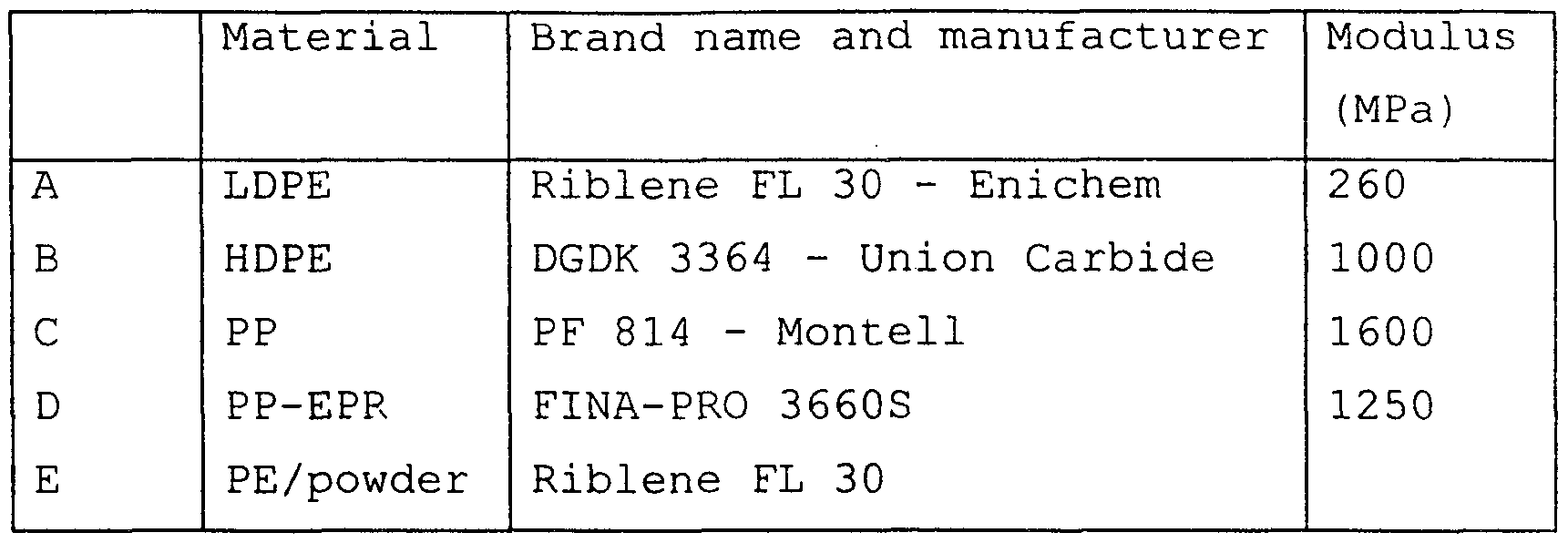
- Examples of commercially available polymer compounds are: low density polyethylene: Riblene FL 30 (Enichem) ; high density polyethylene: DGDK 3364 (Union Carbide) ; polypropylene: PF 814 (Montell); polypropylene modified with EPR: Moplen EP-S 30R, 33R and 81R (Montell); Fina-Pro 5660G, 4660G, 2660S and 3660S (Fina-Pro) .
- the degree of expansion of the polymer and the thickness of the coating layer will have to be such that they ensure, in combination with the outer polymer sheath, resistance to typical impacts which occur during the handling and laying of the cable.
- the Applicant has observed that, insofar as the maintenance of the desired impact-resistance characteristics allows, for an equal thickness of the expanded layer, it is preferable to use a polymer material having a high degree of expansions since, in this way, it is possible to limit the amount of polymer material used, with advantages in terms of both economy and reduced weight of the finished product.
- the degree of expansion is very variable, both as a function of the specific polymer material used and as a function of the thickness of the coating which it is intended to use; in general, this degree of expansion may range from 20% to 3000%, preferably from 30% to 500%, a degree of expansion of between 50% and 200% being particularly preferred.
- the expanded polymer generally has a closed-cell structure. The Applicant has observed that beyond a certain degree of expansion, the capacity of the polymer coating to give the required impact strength decreases. In particular, it has been observed that the possibility of obtaining high degrees of expansion of the polymer by maintaining a high efficacy of protection against impacts may be correlated with the value of the flexural modulus of the polymer to be expanded.
- Ei represents the flexural modulus of the polimer at the lower degree of expansion
- p 2 represents the apparent density of the polymer at the higher degree of expansion
- Pi represents the apparent density of the polymer at the lower degree of expansion
- the thickness of the expanded coating Another variable which is liable to influence the impact strength of the cable is the thickness of the expanded coating; the minimum thickness which is capable of ensuring the impact strength which it is desired to obtain with such a coating will depend mainly on the degree of expansion and on the flexural modulus of this polymer. In general, the Applicant has observed that, for the same polymer and for the same degree of expansion, by increasing the thickness of the expanded coating it is possible to reach higher values of impact strength. However, for the purpose of using a limited amount of coating material, thus decreasing both the costs and the dimensions of the finished product, the thickness of the layer of expanded material will advantageously be the minimum thickness required to ensure the desired impact strength.
- an expanded coating thickness of about 2 mm is usually capable of ensuring a sufficient resistance to the normal impacts to which a cable of this type is subjected.
- the coating thick- ness will be greater than 0.5 mm, in particular between about 1 mm and about 6 mm, a thickness of between 2 mm and 4 mm being particularly preferred.
- N is the result of the product of the two abovementioned values, which will have to be greater than or equal to:
- the parameter V is related to the thickness (S) of the expanded coating by the following relationship:
- V ⁇ (2R 1 -S + S 2 ) where R x represents the inner radius of the circular rim (10a).
- the parameter d e is related to the degree of expansion of the polymer material by the previous relationship:
- this coating will have to have a minimum apparent density of about : 0.40 g/cm 3 for LDPE (Mf of about 200);
- the maximum degree of expansion of polymers which have flexural modulus values close to the upper limits of the intervals defined for the variation of the number N may in reality be even greater than that calculated according to the above relationship; thus, for example, a layer of PP/EPR about 2 mm in thickness (with Mf of about 800 MPa) will still be able to provide the desired impact protection even with a degree of expansion of about 200%.
- the polymer is usually expanded during the extrusion phase; this expansion may either take place chemically, by means of addition of a suitable "expanding" compound, that is to say one which is capable of generating a gas under defined temperature and pressure conditions, or may take place physically, by means of injection of gas at high pressure directly into the extrusion cylinder.
- suitable chemical “expanders” are azodicarboamide, mixtures of organic acids (for example citric acid) with carbonates and/or bicarbonates (for example sodium bicarbonate) .
- gases to be injected at high pressure into the extrusion cylinder are nitrogen, carbon dioxide, air and low-boiling hydrocarbons such as propane and butane.
- the protective outer sheath which clads the layer of expanded polymer may conveniently be of the type normally used.
- Materials for the outer coating which may be used are polyethylene (PE) , in particular medium-density PE (MDPE) and high-density PE (HDPE) , polyvinyl chloride (PVC), mixtures of elastomers and the like. MDPE or PVC is preferably used.
- the polymer material which forms this outer sheath has a flexural modulus of between about 400 and about 1200 MPa, preferably between about 600 MPa and about 1000 MPa.
- the Applicant has observed that the presence of the outer sheath contributes towards providing the coating with the desired impact strength characteristics, in combination with the expanded coating. In particular, the Applicant has observed that this contribution of the sheath towards the impact strength, for the same thickness of expanded coating, increases as the degree of expansion of the polymer which forms this expanded coating increases.
- the thickness of this outer sheath is preferably greater than 0.5 mm, in particular between 1 and 5 mm, preferably between 2 and 4 mm.
- cores are then roped together and the star-shaped spaces are filled with a conventional filling material (for example elastomeric mixtures, polypropylene fibers and the like) , typically by means of extrusion of the filler over the roped cores, so as to obtain a semi-processed cable with a circular cross-section.
- a conventional filling material for example elastomeric mixtures, polypropylene fibers and the like
- the coating of expanded polymer (10) is then extruded over the filling material.
- the die of the extruder head will have a diameter slightly smaller than the final diameter of the cable with expanded coating, in order to allow the polymer to expand outside the extruder.
- the extrusion temperature is one of the process variables which has a considerable influence on the degree of expansion.
- the extrusion temperature is preferably at least 180°C, in particular about 200°C.
- an increase in the extrusion temperature corresponds to a higher degree of expansion .
- the Applicant has observed that it is possible to determine quantitatively the effects of an impact on a cable coating by means of measuring the peel strength of the cable coating layers, dif- ferences between the average value of this peel strength and the value measured at the point of impact being evaluated.
- the peel strength (and the relative difference) may advantageously be measured between the layer of outer semiconductive material and the insulating layer.
- the Applicant has observed that the effects of the particularly severe impacts impacts to which a cable may be subjected, in particular an armored medium-tension cable, may be reproduced by means of an impact test based on the French standard HN 33-S-52, relating to armored cables for high-tension power transmission, which allows for an energy of impact on the cable of about 72 joules (J) .
- the peel strength of the coating layer may be measured according to the French standard HN 33-S-52, according to which the force needed to be applied to separate the outer semiconductive layer from the insulating layer is measured.
- the Applicant has observed that by measuring this force continuously, at the points at which the impact takes place, force peaks are measured which indicate a variation in the cohesive force between the two layers. It was observed that these variations are generally associated with a decrease in the insulating capacity of the coating. The variation will be proportionately larger the smaller the impact strength provided by the outer covering (which, in the case of the present invention, consists of the expanded coating and the outer sheath) .
- variations in the peel strength of up to 20-25% relative to the average value are considered to be acceptable.
- the characteristics of the expanded coating (material, degree of expansion, thickness) , which may advantageously be used together with a suitable protective outer polymer sheath, may be appropriately selectedaccording to the impact protection which it is intended to provide to the underlying cable structure, and also depending on the characteristics of the specific material used as insulator and/or semiconductor, such as hardness of the material, density and the like.
- the cable of the invention is particularly suitable to replace conventional armored cables, due to the advantageous properties of the expanded polymer coating with respect to metal armoring.
- its use should not be limited to such a specific application.
- the cable of the invention may advantageously be employed in all those application wherein a cable having enhanced impact- resistant properties would be desirable.
- the impact-resistant cable of the invention may replace conventional unarmored cables in all those application wherein, up to now, use of armored cables would have been advantageous but has been discouraged due to the drawbacks of the metal armoring.
- test pieces were prepared by extruding variable thicknesses of a few polymers with various degrees of expansion over a core composed of a multi-wire conductor about 14 mm in thickness coated with a layer of 0.5 mm of semiconductive material, a layer of 3 mm of an insulating mixture based on EPR and a further layer of 0.5 mm of "easy stripping" semiconductive material based on EVA supplemented with carbon black, for a total core thickness of about 22 mm.
- Low density polyethylene LDPE
- high density polyethylene HDPE
- polypropylene PP
- PP-EPR PP modified with EPR rubber
- the polymer was expanded chemically, alternatively using two different expanding compounds (CE) , these being identified as follows:
- the polymer to be expanded and the expanding compound were loaded (in the ratios indicated in Table 2) into an 80 mm - 25 D single-screw extruder (Bandera) ; this extruder is equipped with a threaded transfer screw characterized by a depth in the final zone of 9.6 mm.
- the extrusion system consists of a male die capable of providing a smooth throughput of the core to be coated (generally with a diameter which is about 0.5 mm greater than the diameter of the core to be coated) , and a female die in which the diameter is chosen so as to have a size about 2 mm less than the diameter of the cable with the expanded coating; in this way, the extruded material expands on exiting the extrusion head rather than inside this head or inside the extruder.
- the throughput speed of the core to be coated (speed of the extrusion line) is set as a function of the desired thickness of expanded material (see Table 2) .
- a cooling pipe containing cold water
- composition of the polymer material/ expander mixture and the extrusion conditions were varied appropriately, as described in Table 2 below.
- the extrusion temperature relates to the cylinder and extrusion head. When only one value is given, these temperatures are identical . In the initial zone of the extruder, the temperature is about 150 °C .
- Sample 1 did not undergo expansion, presumably because the temperature of the extruder was too low ( 165 °C) , and likewise, for the same reason, Sample 5 underwent limited expansion (only 5% ) .
- the cable with the expanded coating was then subsequently coated with a conventional sheath of MDPE (CE 90 - Materie Plastiche Bresciane) of variable thickness (see Table 3) by means of conventional extrusion methods, thus obtaining cable samples with the characteristics defined in Table 3; cable No. 1, in which the polymer has not undergone expansion, was taken as comparative non-expanded polymer coating.
- Table 3 also gives, for comparative purposes, the characteristics of a cable lacking the expanded filling and coated with only the outer sheath (cable No. 0) .
- the peel strength was measured according to the French standard HN 33-S-52, according to which the force needed to be applied in order to separate the outer semiconductive layer from the insulating layer is measured. By measuring this force continuously, force peaks are measured at the points at which the impact occurred. For each test piece, at the point of impact, a "positive" force peak was measured, corresponding to an increase in the force (relative to the average value) required to separate the two layers, and a "negative” force peak (decrease relative to the average value). From the difference between the maximum (Fmax) and minimum (Fmin) of the force peaks measured, the maximum variation in the peel strength at the point of impact is obtained.
- % variation 100 (Fmax-Fmin) /F ⁇ >
- Table 5 gives the values of the variation in the peel strength for samples 0-17a.
- sample 13 By comparing sample 13 with sample 15, it is seen how an increase in the degree of expansion of the polymer (from 22 to 124%), for the same thickness of the layer of expanded material and of the outer sheath, entails an increase in the impact strength of the coating (going from 16-17% to 10% of variation in the peel strength) . This trend is confirmed by comparing sample 16 with sample 17. However, by comparing samples 16a and 17a (without outer sheath) with the respective samples 16 and 17, it may be seen how the contribution provided by the outer sheath towards the impact protection increases as the degree of expansion increases .
- Cable no. 10 has been tested versus a conventional armored cable, in order to verify the impact strength efficiency of the expanded coating layer.
- the armored cable has the same core as cable no. 10 (i.e. a multi-wire conductor about 14 mm in thickness coated with a layer of 0.5 mm of semiconductive material, a layer of 3 mm of an insulating mixture based on EPR and a further layer of 0.5 mm of "easy stripping" semiconductive material based on EVA supplemented with carbon black, for a total core thickness of about 22 mm) .
- cable no. 10 i.e. a multi-wire conductor about 14 mm in thickness coated with a layer of 0.5 mm of semiconductive material, a layer of 3 mm of an insulating mixture based on EPR and a further layer of 0.5 mm of "easy stripping" semiconductive material based on EVA supplemented with carbon black, for a total core thickness of about 22 mm
- Said core is encircled, from the inside towards the outside of the cable by: a) a layer of rubber-based filling material of about 0.6 mm thickness; b) a sheath of PVC of about 0.6 mm thickness; c) 2 armoring steel tapes of about 0.5 mm thickness each; d) an outer sheath of MDPE of about 2 mm thickness.
- a dynamic machine of the "falling weight" type CEAST, mod. 6758
- the cable of the invention shows even better impact strength performances than a conventional armored cable .
Landscapes
- Insulated Conductors (AREA)
- Organic Insulating Materials (AREA)
- Ropes Or Cables (AREA)
- Paints Or Removers (AREA)
- Manufacture Of Porous Articles, And Recovery And Treatment Of Waste Products (AREA)
Abstract
Description


Claims
Priority Applications (23)
| Application Number | Priority Date | Filing Date | Title |
|---|---|---|---|
| IL13240898A IL132408A (en) | 1997-05-15 | 1998-05-08 | Cable with impact-resistant coating |
| EA199901035A EA001727B1 (en) | 1997-05-15 | 1998-05-08 | Cable with impact-resistant coating |
| NZ337909A NZ337909A (en) | 1997-05-15 | 1998-05-08 | Power transmission cable with impact-resistant expanded polymer coating |
| SK1520-99A SK286369B6 (en) | 1997-05-15 | 1998-05-08 | Cable with impact-resistant coating |
| DK98928233T DK0981821T3 (en) | 1997-05-15 | 1998-05-08 | Cable with shock resistant coating |
| PL98336696A PL187115B1 (en) | 1997-05-15 | 1998-05-08 | Cable with an impact resisting sheathing |
| AU80158/98A AU743873B2 (en) | 1997-05-15 | 1998-05-08 | Cable with impact-resistant coating |
| DE69806377T DE69806377T3 (en) | 1997-05-15 | 1998-05-08 | CABLE WITH HITCH LAYER |
| UA99116185A UA46901C2 (en) | 1997-05-15 | 1998-05-08 | POWER TRANSMISSION CABLE, METHOD FOR IMPROVING CABLE STRENGTH (OPTIONS) AND FOAMED POLYMER MATERIAL |
| SI9830219T SI0981821T1 (en) | 1997-05-15 | 1998-05-08 | Cable with impact-resistant coating |
| AT98928233T ATE220240T1 (en) | 1997-05-15 | 1998-05-08 | CABLE WITH IMPACT RESISTANT LAYER |
| BRPI9809119-0A BR9809119B1 (en) | 1997-05-15 | 1998-05-08 | cable, and processes for imparting impact resistance to an inner structure of a cable and for assessing the impact resistance of a cable, and use of an expanded polymer material. |
| KR10-1999-7010570A KR100493625B1 (en) | 1997-05-15 | 1998-05-08 | Cable with impact-resistant coating |
| CA002289748A CA2289748C (en) | 1997-05-15 | 1998-05-08 | Cable with impact-resistant coating |
| EEP199900489A EE04446B1 (en) | 1997-05-15 | 1998-05-08 | Power cable and method of impinging on the internal structure of the power cable |
| HU0002747A HU223994B1 (en) | 1997-05-15 | 1998-05-08 | Power transmission cable and method for making this cable |
| EP98928233A EP0981821B2 (en) | 1997-05-15 | 1998-05-08 | Cable with impact-resistant coating |
| JP54877198A JP2002510424A (en) | 1997-05-15 | 1998-05-08 | Cable with impact resistant coating |
| APAP/P/1999/001665A AP1121A (en) | 1997-05-15 | 1998-05-08 | Cable with impact-resistant coating. |
| IS5221A IS5221A (en) | 1997-05-15 | 1999-10-19 | Shock resistant cable |
| US09/423,807 US6501027B1 (en) | 1997-05-15 | 1999-11-12 | Cable with impact-resistant coating |
| NO19995535A NO327795B1 (en) | 1997-05-15 | 1999-11-12 | Cable with impact resistant coating |
| US10/289,442 US6768060B2 (en) | 1997-05-15 | 2002-11-07 | Cable with impact-resistant coating |
Applications Claiming Priority (4)
| Application Number | Priority Date | Filing Date | Title |
|---|---|---|---|
| EP97107969.4 | 1997-05-15 | ||
| EP97107969 | 1997-05-15 | ||
| US4712797P | 1997-05-20 | 1997-05-20 | |
| US60/047,127 | 1997-05-20 |
Related Child Applications (1)
| Application Number | Title | Priority Date | Filing Date |
|---|---|---|---|
| US09/423,807 Continuation US6501027B1 (en) | 1997-05-15 | 1999-11-12 | Cable with impact-resistant coating |
Publications (1)
| Publication Number | Publication Date |
|---|---|
| WO1998052197A1 true WO1998052197A1 (en) | 1998-11-19 |
Family
ID=8226797
Family Applications (1)
| Application Number | Title | Priority Date | Filing Date |
|---|---|---|---|
| PCT/EP1998/002698 WO1998052197A1 (en) | 1997-05-15 | 1998-05-08 | Cable with impact-resistant coating |
Country Status (38)
| Country | Link |
|---|---|
| EP (1) | EP0981821B2 (en) |
| JP (1) | JP2002510424A (en) |
| KR (1) | KR100493625B1 (en) |
| CN (1) | CN1308964C (en) |
| AP (1) | AP1121A (en) |
| AR (1) | AR015677A1 (en) |
| AT (1) | ATE220240T1 (en) |
| AU (1) | AU743873B2 (en) |
| BR (1) | BR9809119B1 (en) |
| CA (1) | CA2289748C (en) |
| CZ (1) | CZ293006B6 (en) |
| DE (1) | DE69806377T3 (en) |
| DK (1) | DK0981821T3 (en) |
| DZ (1) | DZ2490A1 (en) |
| EA (1) | EA001727B1 (en) |
| EE (1) | EE04446B1 (en) |
| EG (1) | EG21959A (en) |
| ES (1) | ES2178223T5 (en) |
| GE (1) | GEP20022663B (en) |
| HU (1) | HU223994B1 (en) |
| ID (1) | ID24381A (en) |
| IL (1) | IL132408A (en) |
| MA (1) | MA24545A1 (en) |
| MY (1) | MY117958A (en) |
| NO (1) | NO327795B1 (en) |
| NZ (1) | NZ337909A (en) |
| OA (1) | OA11303A (en) |
| PL (1) | PL187115B1 (en) |
| PT (1) | PT981821E (en) |
| SI (1) | SI0981821T1 (en) |
| SK (1) | SK286369B6 (en) |
| TN (1) | TNSN98064A1 (en) |
| TR (1) | TR199902729T2 (en) |
| TW (1) | TW405126B (en) |
| UY (1) | UY25000A1 (en) |
| WO (1) | WO1998052197A1 (en) |
| YU (1) | YU58199A (en) |
| ZA (1) | ZA984027B (en) |
Cited By (50)
| Publication number | Priority date | Publication date | Assignee | Title |
|---|---|---|---|---|
| WO2001082436A1 (en) * | 2000-04-25 | 2001-11-01 | Pirelli Cavi E Sistemi S.P.A. | Method for protecting joints for electrical cables, protective coating for said joints and joints thus protected |
| WO2002045100A1 (en) * | 2000-11-30 | 2002-06-06 | Pirelli S.P.A. | Process for the production of a multipolar cable, and multipolar cable produced therefrom |
| WO2002099491A1 (en) * | 2001-06-04 | 2002-12-12 | Pirelli & C. S.P.A | Optical cable provided with a mechanically resistant covering |
| WO2003088274A1 (en) * | 2002-04-16 | 2003-10-23 | Pirelli & C. S.P.A. | Electric cable and manufacturing process thereof |
| US6664476B2 (en) | 1998-03-04 | 2003-12-16 | Pirelli Cavi E Sistemi S.P.A. | Electrical cable with self-repairing protection |
| WO2004003939A1 (en) * | 2002-06-28 | 2004-01-08 | Sergio Belli | Impact resistant compact cable |
| US6740396B2 (en) | 2001-02-26 | 2004-05-25 | Pirelli Cavi E Sistemi S.P.A. | Cable with coating of a composite material |
| US6824815B2 (en) | 2000-12-27 | 2004-11-30 | Pirelli Cavi E Sistemi S.P.A. | Process for producing an electrical cable, particularly for high voltage direct current transmission or distribution |
| US6824870B2 (en) | 2000-09-28 | 2004-11-30 | Pirelli S.P.A. | Cable with recyclable covering |
| WO2005015576A1 (en) * | 2003-07-25 | 2005-02-17 | Prysmian Cavi E Sistemi Energia S.R.L. | Continuous process for manufacturing electrical cables |
| US6859590B1 (en) | 1998-07-20 | 2005-02-22 | Pirelli Cavi E Sistemi S.P.A. | Hybrid electrical-optical cable for overhead installation |
| US6903263B2 (en) | 2000-12-27 | 2005-06-07 | Pirelli, S.P.A. | Electrical cable, particularly for high voltage direct current transmission or distribution, and insulating composition |
| US6908673B2 (en) | 2000-06-28 | 2005-06-21 | Pirelli Cavi E Sistemi S.P.A. | Cable with recyclable covering |
| US7060209B2 (en) | 2001-09-10 | 2006-06-13 | Pirelli & C. S.P.A. | Extrusion method and apparatus for producing a cable |
| US7087842B2 (en) | 1999-12-20 | 2006-08-08 | Pirelli Cavi E Sistemi S.P.A. | Electric cable resistant to water penetration |
| US7132604B2 (en) * | 2001-10-22 | 2006-11-07 | Nexans | Cable with an external extruded sheath and method of manufacturing of the cable |
| AU2002314115B2 (en) * | 2001-06-04 | 2007-02-15 | Prysmian Cavi E Sistemi Energia S.R.L. | Optical cable provided with a mechanically resistant covering |
| US7196270B2 (en) | 2003-01-20 | 2007-03-27 | Prysmian Cavi E Sistemi Energia S.R.L. | Cable with recyclable covering layer |
| US7465880B2 (en) | 2000-11-30 | 2008-12-16 | Prysmian Cavi E Sistemi Energia S.R.L. | Process for the production of a multipolar cable, and multipolar cable produced therefrom |
| US7514633B2 (en) * | 2003-12-03 | 2009-04-07 | Prysmian Cavi E Sistemi Energia S.R.L. | Impact resistant cable |
| US7672555B2 (en) | 2003-09-30 | 2010-03-02 | Prysmian Cavi E Sistemi Energia S.R.L. | Cable with a coating layer made from a waste material |
| US7744950B2 (en) | 2000-12-06 | 2010-06-29 | Prysmian Cavi E Sistemi Energia S.R.L. | Process for producing a cable with a recyclable coating comprising a thermoplastic polymer and a dielectric liquid |
| US7790222B2 (en) | 2002-12-23 | 2010-09-07 | Prysmian Cavi E Sistemi Energia S.R.L. | Method for producing a coating layer made of expandable and cross-linkable material in a cable |
| US7884284B2 (en) | 2005-10-25 | 2011-02-08 | Prysmian Cavi E Sistemi Energia S.R.L. | Energy cable comprising a dielectric fluid and a mixture of thermoplastic polymers |
| WO2011092533A1 (en) | 2010-01-29 | 2011-08-04 | Prysmian S.P.A. | Energy cable |
| US7999188B2 (en) | 2007-06-28 | 2011-08-16 | Prysmian S.P.A. | Energy cable |
| WO2012069864A1 (en) | 2010-11-25 | 2012-05-31 | Prysmian S.P.A. | Energy cable having a voltage stabilized thermoplastic electrically insulating layer |
| WO2012084055A1 (en) | 2010-12-23 | 2012-06-28 | Prysmian S.P.A. | Continuous process for manufacturing a high voltage power cable |
| WO2012085612A1 (en) | 2010-12-23 | 2012-06-28 | Prysmian S.P.A. | Energy cable having stabilized dielectric resistance |
| US8257782B2 (en) | 2000-08-02 | 2012-09-04 | Prysmian Cavi E Sistemi Energia S.R.L. | Electrical cable for high voltage direct current transmission, and insulating composition |
| WO2013017916A1 (en) | 2011-08-04 | 2013-02-07 | Prysmian S.P.A. | Energy cable having a thermoplastic electrically insulating layer |
| US8383012B2 (en) | 2007-12-14 | 2013-02-26 | Prysmian S.P.A. | Electric article comprising at least one element made from a semiconductive polymeric material and semiconductive polymeric composition |
| US8475920B2 (en) | 2004-06-28 | 2013-07-02 | Prysmian Cavi E Sistemi Energia Srl | Cable with environmental stress cracking resistance |
| WO2013171550A1 (en) | 2012-05-18 | 2013-11-21 | Prysmian S.P.A. | Process for producing an energy cable having a thermoplastic electrically insulating layer |
| CN103509257A (en) * | 2013-08-30 | 2014-01-15 | 安徽天民电气科技有限公司 | 105 DEG C low-smoke zero-halogen flame-retardant ethylene-propylene-diene monomer cable material and preparation method thereof |
| WO2014076520A1 (en) | 2012-11-14 | 2014-05-22 | Prysmian S.P.A. | Process for recovering wastes of a polymeric composition including a peroxidic crosslinking agent |
| WO2015059520A1 (en) | 2013-10-23 | 2015-04-30 | Prysmian S.P.A. | Energy cable having a crosslinked electrically insulating layer, and method for extracting crosslinking by-products therefrom |
| CN104616808A (en) * | 2015-01-22 | 2015-05-13 | 安徽凌宇电缆科技有限公司 | Low-smoke zero-halogen flame-retardant flexible fireproof medium voltage cable |
| WO2016005791A1 (en) | 2014-07-08 | 2016-01-14 | Prysmian S.P.A. | Energy cable having a thermoplastic electrically insulating layer |
| WO2016097819A1 (en) | 2014-12-17 | 2016-06-23 | Prysmian S.P.A. | Energy cable having a cold-strippable semiconductive layer |
| WO2016116779A1 (en) | 2015-01-21 | 2016-07-28 | Prysmian S.P.A. | Accessory for high voltage direct current energy cables |
| WO2016170391A1 (en) | 2015-04-22 | 2016-10-27 | Prysmian S.P.A. | Energy cable having a crosslinked electrically insulating system, and method for extracting crosslinking by-products therefrom |
| RU167560U1 (en) * | 2016-03-16 | 2017-01-10 | Акционерное общество "Самарская кабельная компания" | HIGH-FREQUENCY COMMUNICATION CABLE, INTENDED FOR DIGITAL TRANSPORT NETWORKS |
| RU167559U1 (en) * | 2016-03-16 | 2017-01-10 | Акционерное общество "Самарская кабельная компания" | COMMUNICATION CABLE LOW-FREQUENCY WITH FILM-PORO-FILM POLYETHYLENE INSULATION |
| WO2018100409A1 (en) | 2016-11-30 | 2018-06-07 | Prysmian S.P.A. | Power cable |
| WO2019043440A1 (en) | 2017-09-04 | 2019-03-07 | Prysmian S.P.A. | Energy cable having a crosslinked electrically insulating layer, and method for extracting crosslinking by-products therefrom |
| US10297372B2 (en) | 2012-05-18 | 2019-05-21 | Prysmian S.P.A | Process for producing an energy cable having a thermoplastic electrically insulating layer |
| IT201900002609A1 (en) | 2019-02-22 | 2020-08-22 | Prysmian Spa | METHOD FOR EXTRACTING CROSS-LINKING BYPRODUCTS FROM A CROSS-LINKED ELECTRICAL INSULATION SYSTEM OF A POWER CABLE AND ITS POWER CABLE. |
| US10818409B2 (en) | 2014-02-07 | 2020-10-27 | General Cable Technologies Corporation | Cables with improved coverings and methods of forming thereof |
| CN114008128A (en) * | 2019-07-01 | 2022-02-01 | 陶氏环球技术有限责任公司 | Expanded low density polyethylene insulation composition |
Families Citing this family (10)
| Publication number | Priority date | Publication date | Assignee | Title |
|---|---|---|---|---|
| CN1961386B (en) | 2004-04-27 | 2010-05-05 | 普雷斯曼电缆及系统能源有限公司 | Process for manufacturing a cable resistant to external chemical agents |
| US7811494B2 (en) | 2004-11-23 | 2010-10-12 | Prysmian Cavi E Sistemi Energia S.R.L. | Cable manufacturing process |
| AU2005330979B2 (en) | 2005-04-27 | 2011-09-15 | Prysmian Cavi E Sistemi Energia S.R.L. | Cable manufacturing process |
| CN101694787B (en) * | 2009-09-28 | 2011-09-21 | 深圳市联嘉祥科技股份有限公司 | Novel coaxial cable and a manufacture method thereof for video security monitoring and control |
| BR112016006186B1 (en) * | 2013-09-23 | 2021-05-18 | Prysmian S.P.A. | Impact resistant multi-pole power cord, and process for producing an impact resistant multi-pole power cord |
| CN105355283A (en) * | 2015-12-10 | 2016-02-24 | 江苏远方电缆厂有限公司 | Improved flexible fireproof cable |
| CN109478446B (en) * | 2016-07-29 | 2022-02-18 | 陶氏环球技术有限责任公司 | Flooding composition comprising bio-based fluid |
| JP6855966B2 (en) * | 2017-07-19 | 2021-04-07 | 住友電装株式会社 | Wire harness |
| JP7124723B2 (en) * | 2019-01-16 | 2022-08-24 | 株式会社オートネットワーク技術研究所 | Insulated wire with adhesive layer |
| DE102019217625A1 (en) * | 2019-11-15 | 2021-05-20 | Contitech Antriebssysteme Gmbh | Elevator belt with cords made of coated strands |
Citations (3)
| Publication number | Priority date | Publication date | Assignee | Title |
|---|---|---|---|---|
| DE1515709A1 (en) * | 1962-10-19 | 1969-06-12 | Felten & Guilleaume Carlswerk | Cold-resistant electrical cable |
| DE8103947U1 (en) * | 1981-02-13 | 1989-11-16 | U. I. Lapp Kg, 7000 Stuttgart, De | |
| DE9216118U1 (en) * | 1992-04-28 | 1993-02-25 | Daetwyler Ag Kabel Und Systeme, Altdorf, Ch |
Family Cites Families (3)
| Publication number | Priority date | Publication date | Assignee | Title |
|---|---|---|---|---|
| FR1228888A (en) † | 1959-03-14 | 1960-09-02 | Comp Generale Electricite | Electric cable having an outer sheath of flexible non-metallic material |
| DE7122512U (en) † | 1971-06-09 | 1971-11-18 | Connollys Ltd | Electrical multi-conductor cable |
| US5110998A (en) † | 1990-02-07 | 1992-05-05 | E. I. Du Pont De Nemours And Company | High speed insulated conductors |
-
1998
- 1998-05-08 PT PT98928233T patent/PT981821E/en unknown
- 1998-05-08 HU HU0002747A patent/HU223994B1/en active IP Right Grant
- 1998-05-08 EE EEP199900489A patent/EE04446B1/en not_active IP Right Cessation
- 1998-05-08 YU YU58199A patent/YU58199A/en unknown
- 1998-05-08 CZ CZ19993989A patent/CZ293006B6/en not_active IP Right Cessation
- 1998-05-08 CA CA002289748A patent/CA2289748C/en not_active Expired - Lifetime
- 1998-05-08 KR KR10-1999-7010570A patent/KR100493625B1/en not_active IP Right Cessation
- 1998-05-08 AP APAP/P/1999/001665A patent/AP1121A/en active
- 1998-05-08 EP EP98928233A patent/EP0981821B2/en not_active Expired - Lifetime
- 1998-05-08 ES ES98928233T patent/ES2178223T5/en not_active Expired - Lifetime
- 1998-05-08 GE GEAP19985084A patent/GEP20022663B/en unknown
- 1998-05-08 NZ NZ337909A patent/NZ337909A/en not_active IP Right Cessation
- 1998-05-08 ID IDW991383A patent/ID24381A/en unknown
- 1998-05-08 PL PL98336696A patent/PL187115B1/en unknown
- 1998-05-08 AU AU80158/98A patent/AU743873B2/en not_active Expired
- 1998-05-08 BR BRPI9809119-0A patent/BR9809119B1/en not_active IP Right Cessation
- 1998-05-08 IL IL13240898A patent/IL132408A/en not_active IP Right Cessation
- 1998-05-08 EA EA199901035A patent/EA001727B1/en not_active IP Right Cessation
- 1998-05-08 SK SK1520-99A patent/SK286369B6/en not_active IP Right Cessation
- 1998-05-08 JP JP54877198A patent/JP2002510424A/en not_active Ceased
- 1998-05-08 WO PCT/EP1998/002698 patent/WO1998052197A1/en active IP Right Grant
- 1998-05-08 SI SI9830219T patent/SI0981821T1/en unknown
- 1998-05-08 AT AT98928233T patent/ATE220240T1/en not_active IP Right Cessation
- 1998-05-08 CN CNB988049716A patent/CN1308964C/en not_active Expired - Lifetime
- 1998-05-08 DE DE69806377T patent/DE69806377T3/en not_active Expired - Lifetime
- 1998-05-08 DK DK98928233T patent/DK0981821T3/en active
- 1998-05-08 TR TR1999/02729T patent/TR199902729T2/en unknown
- 1998-05-13 MA MA25072A patent/MA24545A1/en unknown
- 1998-05-13 DZ DZ980100A patent/DZ2490A1/en active
- 1998-05-13 ZA ZA984027A patent/ZA984027B/en unknown
- 1998-05-14 TW TW087107461A patent/TW405126B/en not_active IP Right Cessation
- 1998-05-14 TN TNTNSN98064A patent/TNSN98064A1/en unknown
- 1998-05-14 EG EG52598A patent/EG21959A/en active
- 1998-05-14 UY UY25000A patent/UY25000A1/en not_active Application Discontinuation
- 1998-05-14 MY MYPI98002149A patent/MY117958A/en unknown
- 1998-05-15 AR ARP980102263A patent/AR015677A1/en active IP Right Grant
-
1999
- 1999-11-09 OA OA9900246A patent/OA11303A/en unknown
- 1999-11-12 NO NO19995535A patent/NO327795B1/en not_active IP Right Cessation
Patent Citations (3)
| Publication number | Priority date | Publication date | Assignee | Title |
|---|---|---|---|---|
| DE1515709A1 (en) * | 1962-10-19 | 1969-06-12 | Felten & Guilleaume Carlswerk | Cold-resistant electrical cable |
| DE8103947U1 (en) * | 1981-02-13 | 1989-11-16 | U. I. Lapp Kg, 7000 Stuttgart, De | |
| DE9216118U1 (en) * | 1992-04-28 | 1993-02-25 | Daetwyler Ag Kabel Und Systeme, Altdorf, Ch |
Cited By (74)
| Publication number | Priority date | Publication date | Assignee | Title |
|---|---|---|---|---|
| US6664476B2 (en) | 1998-03-04 | 2003-12-16 | Pirelli Cavi E Sistemi S.P.A. | Electrical cable with self-repairing protection |
| US6859590B1 (en) | 1998-07-20 | 2005-02-22 | Pirelli Cavi E Sistemi S.P.A. | Hybrid electrical-optical cable for overhead installation |
| US7087842B2 (en) | 1999-12-20 | 2006-08-08 | Pirelli Cavi E Sistemi S.P.A. | Electric cable resistant to water penetration |
| US7195807B2 (en) | 2000-04-25 | 2007-03-27 | Prysmian Cavi E Sistemi Energia S.R.L. | Method for protecting joints for electrical cables, protective coating for said joints and joints thus protected |
| WO2001082436A1 (en) * | 2000-04-25 | 2001-11-01 | Pirelli Cavi E Sistemi S.P.A. | Method for protecting joints for electrical cables, protective coating for said joints and joints thus protected |
| US6908673B2 (en) | 2000-06-28 | 2005-06-21 | Pirelli Cavi E Sistemi S.P.A. | Cable with recyclable covering |
| US8257782B2 (en) | 2000-08-02 | 2012-09-04 | Prysmian Cavi E Sistemi Energia S.R.L. | Electrical cable for high voltage direct current transmission, and insulating composition |
| US6824870B2 (en) | 2000-09-28 | 2004-11-30 | Pirelli S.P.A. | Cable with recyclable covering |
| US7465880B2 (en) | 2000-11-30 | 2008-12-16 | Prysmian Cavi E Sistemi Energia S.R.L. | Process for the production of a multipolar cable, and multipolar cable produced therefrom |
| WO2002045100A1 (en) * | 2000-11-30 | 2002-06-06 | Pirelli S.P.A. | Process for the production of a multipolar cable, and multipolar cable produced therefrom |
| US7816607B2 (en) | 2000-11-30 | 2010-10-19 | Prysmian Cavi E Sistemi Energia S.R.L. | Process for the production of a multipolar cable, and multipolar cable produced therefrom |
| AU2002227940B2 (en) * | 2000-11-30 | 2005-09-29 | Prysmian Cavi E Sistemi Energia S.R.L. | Process for the production of a multipolar cable, and multipolar cable produced therefrom |
| US7744950B2 (en) | 2000-12-06 | 2010-06-29 | Prysmian Cavi E Sistemi Energia S.R.L. | Process for producing a cable with a recyclable coating comprising a thermoplastic polymer and a dielectric liquid |
| US6824815B2 (en) | 2000-12-27 | 2004-11-30 | Pirelli Cavi E Sistemi S.P.A. | Process for producing an electrical cable, particularly for high voltage direct current transmission or distribution |
| US6960726B2 (en) | 2000-12-27 | 2005-11-01 | Pirelli Cavi E Sistemi S.P.A. | Electrical cable, particularly for high voltage direct current transmission or distribution |
| US6903263B2 (en) | 2000-12-27 | 2005-06-07 | Pirelli, S.P.A. | Electrical cable, particularly for high voltage direct current transmission or distribution, and insulating composition |
| US6740396B2 (en) | 2001-02-26 | 2004-05-25 | Pirelli Cavi E Sistemi S.P.A. | Cable with coating of a composite material |
| US7302143B2 (en) | 2001-06-04 | 2007-11-27 | Pirelli & C. S.P.A. | Optical cable provide with a mechanically resistant covering |
| WO2002099491A1 (en) * | 2001-06-04 | 2002-12-12 | Pirelli & C. S.P.A | Optical cable provided with a mechanically resistant covering |
| AU2002314115B2 (en) * | 2001-06-04 | 2007-02-15 | Prysmian Cavi E Sistemi Energia S.R.L. | Optical cable provided with a mechanically resistant covering |
| US7377763B2 (en) | 2001-09-10 | 2008-05-27 | Prysmian Cavi E Sistemi Energia S.R.L. | Extrusion apparatus for producing a cable |
| US7060209B2 (en) | 2001-09-10 | 2006-06-13 | Pirelli & C. S.P.A. | Extrusion method and apparatus for producing a cable |
| US7132604B2 (en) * | 2001-10-22 | 2006-11-07 | Nexans | Cable with an external extruded sheath and method of manufacturing of the cable |
| AU2002367872B2 (en) * | 2002-04-16 | 2008-05-22 | Prysmian Cavi E Sistemi Energia S.R.L. | Electric cable and manufacturing process thereof |
| US7105749B2 (en) | 2002-04-16 | 2006-09-12 | Pirelli & C. S.P.A. | Electric cable and manufacturing process thereof |
| WO2003088274A1 (en) * | 2002-04-16 | 2003-10-23 | Pirelli & C. S.P.A. | Electric cable and manufacturing process thereof |
| WO2004003939A1 (en) * | 2002-06-28 | 2004-01-08 | Sergio Belli | Impact resistant compact cable |
| WO2004003940A1 (en) * | 2002-06-28 | 2004-01-08 | Pirelli & C. S.P.A. | Impact resistant compact cable |
| AU2003236698B2 (en) * | 2002-06-28 | 2008-10-16 | Prysmian Cavi E Sistemi Energia S.R.L. | Impact resistant compact cable |
| US7488892B2 (en) | 2002-06-28 | 2009-02-10 | Prysmian Cavi E Sistemi Energia S.R.L. | Impact resistant compact cable |
| US7790222B2 (en) | 2002-12-23 | 2010-09-07 | Prysmian Cavi E Sistemi Energia S.R.L. | Method for producing a coating layer made of expandable and cross-linkable material in a cable |
| US7196270B2 (en) | 2003-01-20 | 2007-03-27 | Prysmian Cavi E Sistemi Energia S.R.L. | Cable with recyclable covering layer |
| WO2005015576A1 (en) * | 2003-07-25 | 2005-02-17 | Prysmian Cavi E Sistemi Energia S.R.L. | Continuous process for manufacturing electrical cables |
| AU2003294942B2 (en) * | 2003-07-25 | 2009-07-23 | Prysmian Cavi E Sistemi Energia S.R.L. | Continuous process for manufacturing electrical cables |
| AU2003250174B2 (en) * | 2003-07-25 | 2010-01-28 | Prysmian Cavi E Sistemi Energia S.R.L. | Continuous process for manufacturing electrical cables |
| US7459635B2 (en) | 2003-07-25 | 2008-12-02 | Prysmian Cavi E Sistemi Energia S.R.L. | Continuous process for manufacturing electrical cables |
| WO2005015577A1 (en) * | 2003-07-25 | 2005-02-17 | Pirelli & C. S.P.A. | Continuous process for manufacturing electrical cables |
| US7672555B2 (en) | 2003-09-30 | 2010-03-02 | Prysmian Cavi E Sistemi Energia S.R.L. | Cable with a coating layer made from a waste material |
| AU2003300518B2 (en) * | 2003-12-03 | 2010-08-19 | Prysmian Cavi E Sistemi Energia S.R.L. | Impact resistant cable |
| US7514633B2 (en) * | 2003-12-03 | 2009-04-07 | Prysmian Cavi E Sistemi Energia S.R.L. | Impact resistant cable |
| US8475920B2 (en) | 2004-06-28 | 2013-07-02 | Prysmian Cavi E Sistemi Energia Srl | Cable with environmental stress cracking resistance |
| US7884284B2 (en) | 2005-10-25 | 2011-02-08 | Prysmian Cavi E Sistemi Energia S.R.L. | Energy cable comprising a dielectric fluid and a mixture of thermoplastic polymers |
| US7999188B2 (en) | 2007-06-28 | 2011-08-16 | Prysmian S.P.A. | Energy cable |
| US8383012B2 (en) | 2007-12-14 | 2013-02-26 | Prysmian S.P.A. | Electric article comprising at least one element made from a semiconductive polymeric material and semiconductive polymeric composition |
| US10811163B2 (en) | 2010-01-29 | 2020-10-20 | Prysmian S.P.A. | Energy cable |
| WO2011092533A1 (en) | 2010-01-29 | 2011-08-04 | Prysmian S.P.A. | Energy cable |
| WO2012069864A1 (en) | 2010-11-25 | 2012-05-31 | Prysmian S.P.A. | Energy cable having a voltage stabilized thermoplastic electrically insulating layer |
| WO2012084055A1 (en) | 2010-12-23 | 2012-06-28 | Prysmian S.P.A. | Continuous process for manufacturing a high voltage power cable |
| WO2012085612A1 (en) | 2010-12-23 | 2012-06-28 | Prysmian S.P.A. | Energy cable having stabilized dielectric resistance |
| US9576703B2 (en) | 2010-12-23 | 2017-02-21 | Prysmian S.P.A. | Energy cable having stabilized dielectric resistance |
| WO2013017916A1 (en) | 2011-08-04 | 2013-02-07 | Prysmian S.P.A. | Energy cable having a thermoplastic electrically insulating layer |
| WO2013171550A1 (en) | 2012-05-18 | 2013-11-21 | Prysmian S.P.A. | Process for producing an energy cable having a thermoplastic electrically insulating layer |
| US10297372B2 (en) | 2012-05-18 | 2019-05-21 | Prysmian S.P.A | Process for producing an energy cable having a thermoplastic electrically insulating layer |
| WO2014076520A1 (en) | 2012-11-14 | 2014-05-22 | Prysmian S.P.A. | Process for recovering wastes of a polymeric composition including a peroxidic crosslinking agent |
| US9605127B2 (en) | 2012-11-14 | 2017-03-28 | Prysmian S.P.A | Process for recovering wastes of a polymeric composition including a peroxidic crosslinking agent |
| CN103509257A (en) * | 2013-08-30 | 2014-01-15 | 安徽天民电气科技有限公司 | 105 DEG C low-smoke zero-halogen flame-retardant ethylene-propylene-diene monomer cable material and preparation method thereof |
| WO2015059520A1 (en) | 2013-10-23 | 2015-04-30 | Prysmian S.P.A. | Energy cable having a crosslinked electrically insulating layer, and method for extracting crosslinking by-products therefrom |
| US10325694B2 (en) | 2013-10-23 | 2019-06-18 | Prysmian S.P.A | Energy cable having a crosslinked electrically insulating layer, and method for extracting crosslinking by-products therefrom |
| US10818409B2 (en) | 2014-02-07 | 2020-10-27 | General Cable Technologies Corporation | Cables with improved coverings and methods of forming thereof |
| WO2016005791A1 (en) | 2014-07-08 | 2016-01-14 | Prysmian S.P.A. | Energy cable having a thermoplastic electrically insulating layer |
| WO2016097819A1 (en) | 2014-12-17 | 2016-06-23 | Prysmian S.P.A. | Energy cable having a cold-strippable semiconductive layer |
| WO2016116779A1 (en) | 2015-01-21 | 2016-07-28 | Prysmian S.P.A. | Accessory for high voltage direct current energy cables |
| CN104616808A (en) * | 2015-01-22 | 2015-05-13 | 安徽凌宇电缆科技有限公司 | Low-smoke zero-halogen flame-retardant flexible fireproof medium voltage cable |
| US10361010B2 (en) | 2015-04-22 | 2019-07-23 | Prysmian S.P.A. | Energy cable having a crosslinked electrically insulating system, and method for extracting crosslinking by-products therefrom |
| WO2016170391A1 (en) | 2015-04-22 | 2016-10-27 | Prysmian S.P.A. | Energy cable having a crosslinked electrically insulating system, and method for extracting crosslinking by-products therefrom |
| RU167560U1 (en) * | 2016-03-16 | 2017-01-10 | Акционерное общество "Самарская кабельная компания" | HIGH-FREQUENCY COMMUNICATION CABLE, INTENDED FOR DIGITAL TRANSPORT NETWORKS |
| RU167559U1 (en) * | 2016-03-16 | 2017-01-10 | Акционерное общество "Самарская кабельная компания" | COMMUNICATION CABLE LOW-FREQUENCY WITH FILM-PORO-FILM POLYETHYLENE INSULATION |
| WO2018100409A1 (en) | 2016-11-30 | 2018-06-07 | Prysmian S.P.A. | Power cable |
| WO2019043440A1 (en) | 2017-09-04 | 2019-03-07 | Prysmian S.P.A. | Energy cable having a crosslinked electrically insulating layer, and method for extracting crosslinking by-products therefrom |
| US10886035B2 (en) | 2017-09-04 | 2021-01-05 | Prysmian S.P.A. | Energy cable having a crosslinked electrically insulating layer, and method for extracting crosslinking by-products therefrom |
| IT201900002609A1 (en) | 2019-02-22 | 2020-08-22 | Prysmian Spa | METHOD FOR EXTRACTING CROSS-LINKING BYPRODUCTS FROM A CROSS-LINKED ELECTRICAL INSULATION SYSTEM OF A POWER CABLE AND ITS POWER CABLE. |
| EP3699931A1 (en) | 2019-02-22 | 2020-08-26 | Prysmian S.p.A. | Method for extracting crosslinking by-products from a crosslinked electrically insulating system of a power cable and related power cable |
| US10930414B2 (en) | 2019-02-22 | 2021-02-23 | Prysmian S.P.A. | Method for extracting crosslinking by-products from a crosslinked electrically insulating system of a power cable and related power cable |
| CN114008128A (en) * | 2019-07-01 | 2022-02-01 | 陶氏环球技术有限责任公司 | Expanded low density polyethylene insulation composition |
Also Published As
Similar Documents
| Publication | Publication Date | Title |
|---|---|---|
| EP0981821B1 (en) | Cable with impact-resistant coating | |
| US6768060B2 (en) | Cable with impact-resistant coating | |
| CA2614027C (en) | Cable having expanded, strippable jacket | |
| CA2589166C (en) | Electrical power cable having expanded polymeric layers | |
| EP1495474B1 (en) | Electric cable and manufacturing process thereof | |
| MXPA99010479A (en) | Cable with impact-resistant coating |
Legal Events
| Date | Code | Title | Description |
|---|---|---|---|
| WWE | Wipo information: entry into national phase |
Ref document number: 132408 Country of ref document: IL Ref document number: P-581/99 Country of ref document: YU Ref document number: 98804971.6 Country of ref document: CN |
|
| AK | Designated states |
Kind code of ref document: A1 Designated state(s): AL AU BA BB BG BR CA CN CU CZ EE GE GW HU ID IL IS JP KP KR LC LK LR LS LT MK MN MX NO NZ PL RO SG SI SK SL TR UA US UZ VN YU |
|
| AL | Designated countries for regional patents |
Kind code of ref document: A1 Designated state(s): GH GM KE LS MW SD SZ UG ZW AM AZ BY KG KZ MD RU TJ TM AT BE CH CY DE DK ES FI FR GB GR IE IT LU MC NL PT SE BF BJ CF CG CI CM GA GN ML MR NE SN TD TG |
|
| DFPE | Request for preliminary examination filed prior to expiration of 19th month from priority date (pct application filed before 20040101) | ||
| 121 | Ep: the epo has been informed by wipo that ep was designated in this application | ||
| WWE | Wipo information: entry into national phase |
Ref document number: 337909 Country of ref document: NZ |
|
| WWE | Wipo information: entry into national phase |
Ref document number: 1999/02729 Country of ref document: TR |
|
| WWE | Wipo information: entry into national phase |
Ref document number: 152099 Country of ref document: SK |
|
| WWE | Wipo information: entry into national phase |
Ref document number: PV1999-3989 Country of ref document: CZ |
|
| WWE | Wipo information: entry into national phase |
Ref document number: 80158/98 Country of ref document: AU Ref document number: 09423807 Country of ref document: US |
|
| ENP | Entry into the national phase |
Ref document number: 2289748 Country of ref document: CA Ref document number: 2289748 Country of ref document: CA Kind code of ref document: A |
|
| WWE | Wipo information: entry into national phase |
Ref document number: PA/a/1999/010479 Country of ref document: MX Ref document number: 1019997010570 Country of ref document: KR Ref document number: 1199900955 Country of ref document: VN |
|
| WWE | Wipo information: entry into national phase |
Ref document number: 1998928233 Country of ref document: EP |
|
| WWE | Wipo information: entry into national phase |
Ref document number: 199901035 Country of ref document: EA |
|
| WWP | Wipo information: published in national office |
Ref document number: 1998928233 Country of ref document: EP |
|
| WWP | Wipo information: published in national office |
Ref document number: PV1999-3989 Country of ref document: CZ |
|
| WWP | Wipo information: published in national office |
Ref document number: 1019997010570 Country of ref document: KR |
|
| WWG | Wipo information: grant in national office |
Ref document number: 80158/98 Country of ref document: AU |
|
| WWG | Wipo information: grant in national office |
Ref document number: 1998928233 Country of ref document: EP |
|
| WWG | Wipo information: grant in national office |
Ref document number: PV1999-3989 Country of ref document: CZ |
|
| WWG | Wipo information: grant in national office |
Ref document number: 1019997010570 Country of ref document: KR |