US9902586B2 - Sheet processing apparatus capable of creating fold section, method of controlling the same, and storage medium - Google Patents
Sheet processing apparatus capable of creating fold section, method of controlling the same, and storage medium Download PDFInfo
- Publication number
- US9902586B2 US9902586B2 US13/924,739 US201313924739A US9902586B2 US 9902586 B2 US9902586 B2 US 9902586B2 US 201313924739 A US201313924739 A US 201313924739A US 9902586 B2 US9902586 B2 US 9902586B2
- Authority
- US
- United States
- Prior art keywords
- sheet
- bookbinding
- cpu
- button
- lap
- Prior art date
- Legal status (The legal status is an assumption and is not a legal conclusion. Google has not performed a legal analysis and makes no representation as to the accuracy of the status listed.)
- Active, expires
Links
Images


Classifications
-
- B—PERFORMING OPERATIONS; TRANSPORTING
- B65—CONVEYING; PACKING; STORING; HANDLING THIN OR FILAMENTARY MATERIAL
- B65H—HANDLING THIN OR FILAMENTARY MATERIAL, e.g. SHEETS, WEBS, CABLES
- B65H45/00—Folding thin material
-
- B—PERFORMING OPERATIONS; TRANSPORTING
- B65—CONVEYING; PACKING; STORING; HANDLING THIN OR FILAMENTARY MATERIAL
- B65H—HANDLING THIN OR FILAMENTARY MATERIAL, e.g. SHEETS, WEBS, CABLES
- B65H37/00—Article or web delivery apparatus incorporating devices for performing specified auxiliary operations
- B65H37/04—Article or web delivery apparatus incorporating devices for performing specified auxiliary operations for securing together articles or webs, e.g. by adhesive, stitching or stapling
-
- B—PERFORMING OPERATIONS; TRANSPORTING
- B65—CONVEYING; PACKING; STORING; HANDLING THIN OR FILAMENTARY MATERIAL
- B65H—HANDLING THIN OR FILAMENTARY MATERIAL, e.g. SHEETS, WEBS, CABLES
- B65H37/00—Article or web delivery apparatus incorporating devices for performing specified auxiliary operations
- B65H37/06—Article or web delivery apparatus incorporating devices for performing specified auxiliary operations for folding
-
- B—PERFORMING OPERATIONS; TRANSPORTING
- B65—CONVEYING; PACKING; STORING; HANDLING THIN OR FILAMENTARY MATERIAL
- B65H—HANDLING THIN OR FILAMENTARY MATERIAL, e.g. SHEETS, WEBS, CABLES
- B65H2801/00—Application field
- B65H2801/24—Post -processing devices
- B65H2801/27—Devices located downstream of office-type machines
-
- B—PERFORMING OPERATIONS; TRANSPORTING
- B65—CONVEYING; PACKING; STORING; HANDLING THIN OR FILAMENTARY MATERIAL
- B65H—HANDLING THIN OR FILAMENTARY MATERIAL, e.g. SHEETS, WEBS, CABLES
- B65H45/00—Folding thin material
- B65H45/12—Folding articles or webs with application of pressure to define or form crease lines
- B65H45/18—Oscillating or reciprocating blade folders
-
- B—PERFORMING OPERATIONS; TRANSPORTING
- B65—CONVEYING; PACKING; STORING; HANDLING THIN OR FILAMENTARY MATERIAL
- B65H—HANDLING THIN OR FILAMENTARY MATERIAL, e.g. SHEETS, WEBS, CABLES
- B65H45/00—Folding thin material
- B65H45/12—Folding articles or webs with application of pressure to define or form crease lines
- B65H45/28—Folding in combination with cutting
Definitions
- the present invention relates to a sheet processing apparatus, a method of controlling the same, and a storage medium.
- a folding position for center-fold processing is sometimes displaced from the center of a sheet.
- the displacement of the folding position from the middle of a sheet is caused e.g. by an assembly error of a sheet processing apparatus, variation in sheets between production lots of the sheets, and a change in sheets due to changes in environmental conditions, such as humidity and temperature.
- the two setting items are an item which can be set only by a service technician for correcting the above-mentioned displacement due to an assembly error, and an item which can be set by a user for correcting displacement due to a sheet.
- processing operations up to center-fold processing are performed by a sheet processing apparatus, and subsequent processing operations including saddle-stitch processing are performed using another sheet processing apparatus (off-line apparatus) which is different from the above-mentioned sheet processing apparatus.
- the off-line apparatuses include one configured to feed sheets one by one by pinching an extending portion (portion of a sheet, which does not overlap when being folded) of an end of a sheet with rollers. In the off-line apparatus of this type, if a sheet is folded in the middle, an extending portion of an end of the sheet is not generated, and as a result, the off-line apparatus cannot accurately feed the sheet (fold section, i.e. signature).
- a production method in which saddle-stitch processing and processing steps thereafter are performed using an off-line apparatus is generally determined from the viewpoint of productivity, based on related factors, such as a difference in the number of sheets which can be bound, a level of the accuracy of binding, and a level of speed at which the off-line apparatus can perform processing.
- a print product generated by the sheet processing apparatus is required to have a center-folding position shifted from the center of a sheet by a predetermined length.
- the sheet processing apparatus disclosed in Japanese Patent Laid-Open Publication No. 2001-206626 is capable of performing fine adjustment for correcting the displacement of a folding position from the center of a sheet, caused by the above-mentioned assembly error, and displacement of a folding position from the center of a sheet, caused by the above-mentioned variation in sheets.
- the sheet processing apparatus disclosed in Japanese Patent Laid-Open Publication No. 2001-206626 does not take into consideration shifting of a folding position from the center of a sheet, and further, is not capable of performing adjustment large enough to create a fold section, a fore edge of which is generally required to have a length of 5 mm to 10 mm, demanded by the above-mentioned production method.
- the present invention provides a sheet processing apparatus that is capable of creating fold sections which are suitable for an apparatus that performs saddle-stitch processing on fold sections, a method of controlling the sheet processing apparatus, and a storage medium.
- a sheet processing apparatus capable of performing folding processing on sheets, comprising a receiving unit configured to receive a distance between a first sheet end and a second sheet end of each sheet assumed to have been folded in two, and a control unit configured to control folding of the sheet such that the distance between the first sheet end and the second sheet end becomes the distance received by the receiving unit.
- a method of controlling a sheet processing apparatus capable of performing folding processing on sheets comprising receiving a distance between a first sheet end and a second sheet end of each sheet assumed to have been folded in two, and controlling folding of the sheet such that the distance between the first sheet end and the second sheet end becomes the received distance.
- a non-transitory computer-readable storage device storing a computer-executable program for causing a computer to execute a method of controlling a sheet processing apparatus capable of performing folding processing on sheets, wherein the method comprises receiving a distance between a first sheet end and a second sheet end of each sheet assumed to have been folded in two, and controlling folding of the sheet such that the distance between the first sheet end and the second sheet end becomes the received distance.
- a sheet processing apparatus that is capable of creating fold sections suitable for an apparatus that performs saddle-stitch processing on fold sections, a method of controlling the same, and a storage medium.
- FIG. 1 is a diagram showing the mechanical configuration of a sheet processing apparatus according to a first embodiment of the present invention.
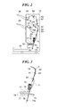
- FIG. 2 is a diagram useful in explaining the construction and operation of a finisher appearing in FIG. 1 .
- FIG. 3 is a diagram useful in explaining the construction and operation of the finisher appearing in FIG. 1 .
- FIG. 4 is a diagram useful in explaining the construction and operation of the finisher appearing in FIG. 1 .
- FIG. 5 is a diagram useful in explaining the construction and operation of the finisher appearing in FIG. 1 .
- FIG. 6 is a diagram useful in explaining the construction and operation of the finisher appearing in FIG. 1 .
- FIG. 7 is a diagram useful in explaining the construction and operation of the finisher appearing in FIG. 1 .
- FIG. 8 is a diagram showing the electrical configuration of the sheet processing apparatus according to the first embodiment.
- FIG. 9 is a diagram showing software module configuration of the sheet processing apparatus according to the first embodiment.
- FIGS. 10A to 10F are schematic diagrams of screens which are displayed on a console section appearing in FIG. 8 .
- FIG. 11 is a flowchart of a waiting-time process executed by a CPU appearing in FIG. 8 .
- FIG. 12 is a flowchart of a scanning process executed by the CPU appearing in FIG. 8 .
- FIG. 13 is a flowchart of an output sheet-setting process executed by the CPU appearing in FIG. 8 .
- FIG. 14 is a flowchart of a bookbinding determination process executed by the CPU appearing in FIG. 8 .
- FIG. 15 is a flowchart of a printing process executed by the CPU appearing in FIG. 8 .
- FIG. 16 is a flowchart of a finishing process executed by the CPU appearing in FIG. 8 .
- FIG. 17 is a flowchart of a fold setting process executed by the CPU appearing in FIG. 8 .
- FIG. 18 is a view of an example of an output obtained when a bookbinding lap is set and processing operations up to center-fold processing have been performed by the sheet processing apparatus according to the first embodiment.
- FIGS. 19A and 19B are schematic diagrams showing post-processing steps executed by a post-processing apparatus.
- FIG. 20 is a cross-sectional view of a fold section-supplying unit appearing in FIG. 19B .
- FIGS. 21A and 21B are diagrams useful in explaining automatic print adjustment performed in accordance with bookbinding lap adjustment, by a sheet processing apparatus according to a second embodiment of the present invention.
- FIG. 22 is a flowchart of a print instruction process executed in the second embodiment by the CPU appearing in FIG. 8 .
- FIG. 23A is a diagram useful in explaining a change of an imposition reference position calculated by the CPU in a step in the print instruction process shown in FIG. 22 .
- FIG. 23B is a diagram useful in explaining a creep correction amount calculated by the CPU in a step in the print instruction process shown in FIG. 22 .
- FIG. 23C is a diagram useful in explaining a print position adjustment amount calculated by the CPU in a step in the print instruction process shown in FIG. 22 .
- FIG. 24 is a diagram showing a saddle-stitch processing apparatus registration screen used in a third embodiment of the present invention, for registering a device that performs saddle-stitch processing.
- FIG. 25 is a flowchart of a fold setting process executed in the third embodiment by the CPU appearing in FIG. 8 .
- FIG. 1 is a diagram showing the mechanical configuration of a sheet processing apparatus 90 according to a first embodiment of the present invention.
- the sheet processing apparatus 90 may be a single-function apparatus.
- the sheet processing apparatus 90 includes a scanner 119 , a document feeder (DF) 2 , a printer engine 120 including drums for four colors, a sheet feeding deck 14 , and a finisher 109 .
- a light source 10 irradiates the original with light, and reflected light enters a CCD 43 through a reflective plate 11 and a lens 12 .
- the CCD 43 converts the light having entered therein to a digital signal, and sends the converted signal to a controller unit 100 (see FIG. 8 ) of the scanner 119 .
- the controller unit 100 performs desired image processing on the received digital signal, converts the processed signal to a laser recording signal, and stores the laser recording signal in a memory (RAM 102 : see FIG. 8 ) provided therein as image data.
- RAM 102 see FIG. 8
- an original detection sensor 4 detects that the original has been set.
- the controller unit 100 causes an original feeding roller 5 and a conveyance belt 6 to rotate to thereby convey the original to a predetermined position on the original platen glass.
- the controller unit 100 After the original is conveyed to the predetermined position, the controller unit 100 performs the same scan operation as that performed on the original platen glass, and stores the scanned image data in the memory. Then, the controller unit 100 discharges the original having been read onto an original discharge tray 9 .
- the controller unit 100 causes an original having been read to be discharged, and at the same time causes a next original to be fed to the original platen glass via the original feeding roller 5 to thereby perform the operation for scanning the next original.
- the operation for reading the plurality of originals is performed.
- a recording signal (print image data) temporarily stored in the memory within the controller unit 100 is transferred to the printer engine 120 , and is converted to recording laser beams for respective colors of yellow, magenta, cyan, and black by a laser recording section.
- the converted recording laser beams are irradiated onto photosensitive members 16 for the respective colors to thereby form electrostatic latent images on the respective photosensitive members.
- the electrostatic latent images are developed with toner supplied from toner cartridges 17 , respectively, and the thus visualized images are primarily transferred onto an intermediate transfer belt 21 as a primary transfer image.
- the intermediate transfer belt 21 is rotated clockwise, and when a recording sheet fed from one of sheet feed cassettes 18 or the sheet feeding deck 14 along a sheet feeding conveying path 19 has reached a secondary transfer position 20 , the primary transfer image is transferred from the intermediate transfer belt 21 onto the recording sheet.
- the recording sheet having the image transferred thereon is pressed and heated by a fixing device 22 to have the toner fixed thereon, and is conveyed along a discharge conveying path. Then, the recording sheet is discharged onto a center tray 23 in a face-down manner or is switched back to a discharge outlet 24 which guides the recording sheet to the finisher 109 , or is discharged onto a side tray 25 in a face-up manner.
- Flappers 26 and 27 are used for switching the conveying path in order to switch these discharge outlets.
- the flapper 27 switches the conveying path after the recording sheet passes the fixing device 22 , and then the recording sheet is switched back and conveyed downward through a double-sided printing conveying path 31 to the secondary transfer position 20 again, whereby a double-sided printing operation is achieved.
- Double-sided printing circulation control is performed using the conveying paths including the double-sided printing conveying path 31 , the secondary transfer position 20 , and the fixing device 22 .
- Five-sheet circulation control is performed for A-4 size sheets and LTR size sheets, and three-sheet circulation control is performed for sheets having a size larger than the A-4 and LTR sizes.
- the finisher 109 performs post-processing on a sheet according to settings designated by the user. More specifically, the finisher 109 has functions of stapling (one-point stapling/two-point stapling), punching (two-hole punching/three-hole punching), and saddle-stitch processing.
- the finisher 109 appearing in FIG. 1 includes discharge trays 28 , 29 , and 30 , and a sheet having passed through the discharge outlet 24 which guides a sheet to the finisher 109 is discharged onto one of the discharge trays associated with the respective functions of copying, printing, and facsimile, according to a setting designated by the user.
- various settings such as settings for monochrome printing, color printing, a sheet size, 2-up/4-up printing/N-up printing, double-sided printing, stapling, punching, saddle-stitching, a lining board, a cover, and a back cover, can be made using a driver.
- the finisher 109 includes conveying rollers 61 to 69 , leading edge detection sensors 50 and 53 , a skew correction roller 51 , a loop space 52 , a conveying path 71 , a stapler 72 , a thrusting plate 73 , a stopper 74 , folding rollers 75 and 76 , and bundle conveying roller pairs 77 and 78 .
- S denotes a sheet.
- the finisher 109 may be operated according to commands from the controller unit 100 of the sheet processing apparatus 90 , or may be operated by a controller unit of its own.
- a sheet conveyed from the sheet processing apparatus 90 is discharged onto one of the discharge trays 28 , 29 , and 30 according to a type of sheet processing set by the user.
- center-fold bookbinding processing includes center-fold processing
- saddle-stitch bookbinding processing includes center-fold processing and saddle-stitch processing.
- the sheet conveyed from the sheet processing apparatus 90 is conveyed by the conveying rollers 61 to 68 until a leading edge of the sheet reaches the leading edge detection sensor 50 . Then, as shown in FIG. 3 , when the leading edge of the sheet is detected by the leading edge detection sensor 50 , a speed of the conveying roller 68 nipping the sheet is reduced, and the leading edge of the sheet is brought into abutment with a nip of the skew correction roller 51 .
- the conveying roller 68 continues to be rotated for a while. Then, the sheet forms a loop or bend in the loop space 52 , and then the conveying roller 68 is stopped.
- the skew correction roller 51 starts rotation thereof. If the sheet is skewed, the skew is corrected by the skew correction roller 51 .
- the sheet subjected to skew correction is conveyed toward the conveying roller 69 .
- the sheet is conveyed by a predetermined amount from the time point when the leading edge of the sheet is detected by the leading edge detection sensor 53 , whereby the leading edge of the sheet is brought into abutment with a stopper 74 a.
- the sheet is positioned by the stopper 74 a such that a stapling position to be stapled by the stapler 72 is arranged in the center of the sheet.
- the sheets to be conveyed into the conveying path 71 are sequentially conveyed in such a manner that a sheet material to be set at the innermost location of the booklet is first conveyed, and a cover of the booklet is finally conveyed.
- the stapler 72 performs binding processing on the sheet bundle 81 .
- the stopper 74 a having supported the sheet bundle 81 is moved downstream in a conveying direction, and serves as a stopper 74 b as shown in FIG. 5 .
- the sheet bundle 81 is moved downstream in the conveying direction in accordance with the movement of the stopper.
- the stopper is positioned at a location of the stopper 74 b from the start of conveying the sheets, and stapling by the stapler 72 is omitted.
- the stopper 74 b positions the sheet bundle 81 such that the center of the sheet bundle 81 is arranged at a location of the thrusting plate 73 . Then, a front end of the thrusting plate 73 is brought into abutment with a portion of the sheet bundle 81 positioned by the stopper 74 b , where a fold line is to be formed, and as shown in FIG. 6 , the sheet bundle is thrust in a nip between the folding rollers 75 and 76 to thereby form a fold line on the sheet material.
- the sheet bundle 81 folded and formed with the fold line by the folding rollers 75 and 76 is discharged onto the discharge tray 30 by the bundle conveying roller pairs 77 and 78 as shown in FIG. 7 .
- FIG. 8 is a diagram showing the electrical configuration of the sheet processing apparatus 90 according to the first embodiment of the present invention.
- the sheet processing apparatus 90 includes the controller unit 100 that controls the overall operation of the sheet processing apparatus 90 , the finisher 109 that performs post-processing, and the scanner 119 as an image input device.
- the sheet processing apparatus 90 further includes the printer engine 120 as an image output device, and a console section 121 used for inputting instructions from an operator and displaying information to the operator.
- the finisher 109 , the scanner 119 , the printer engine 120 , and the console section 121 are connected to the controller unit 100 , and are controlled according to instructions from the controller unit 100 .
- the scanner 119 is connected to a scanner image processing section 117 of the controller unit 100
- the printer engine 120 is connected to a printer image processing section 118 of the controller unit 100 .
- the controller unit 100 includes a CPU 101 .
- the CPU 101 is connected to the RAM 102 , a ROM 103 , an HDD 104 , an image bus interface 105 , a console section interface 106 , an accessory interface 108 , and a network interface 107 , via a system bus 110 .
- the RAM 102 is a memory for providing a work area for the CPU 101 .
- the RAM 102 is used as a set value-storing memory for temporarily storing parameter setting values, and an image memory for storing part of image data.
- the ROM 103 is a boot ROM which stores a system boot program.
- the HDD 104 stores system software, history of the parameter setting values, image data, and so on.
- the CPU 101 is capable of loading the system boot program stored in the ROM 103 into the RAM 102 . By thus loading the system boot program in the RAM 102 , the CPU 101 becomes capable of executing a controller program.
- the console section interface 106 is an interface for inputting and outputting information and data to and from the console section 121 .
- the console section interface 106 outputs image data to be displayed to the console section 121 according to instructions from the CPU 101 , and transfers information input by the operator via the console section 121 to the CPU 101 .
- the accessory interface 108 is connected to the finisher 109 , and transfers data of a type of post-processing, set values, adjustment values, and a device status, to the finisher 109 according to instructions received from the CPU 101 .
- the finisher 109 is a device for performing post-processing, and the types of the finisher to be connected include a stapling unit, a folding machine, and a puncher.
- the network interface 107 is connected to a LAN 122 , and performs inputting and outputting of information to and from the LAN 122 .
- the image bus interface 105 is a bus bridge that connects between the system bus 110 and an image bus 111 , and converts data structure.
- a RIP 112 rasterizes a PDL code received from the LAN 122 into a bitmap image.
- An image-editing image processing section 114 performs image processing on data of original images read by the scanner 119 or stored in the HDD 104 .
- An image expansion section 115 decodes and expands image data stored in the HDD 104 in a compressed and encoded state before the image data is subjected to image processing by the printer image processing section 118 and is then output to the printer engine 120 .
- an image compression section 116 encodes image data processed by the RIP 112 and the scanner image processing section 117 by a predetermined compression method before storing the same in the HDD 104 .
- the device interface 113 is connected to the scanner 119 and the printer engine 120 via the scanner image processing section 117 and the printer image processing section 118 , respectively, and performs synchronous-to-asynchronous or asynchronous-to-synchronous conversion of image data, and transfer of data of set values, adjustment values, and a device status.
- the scanner image processing section 117 performs various kinds of processing, including correction, processing, image area separation, scaling, binarization, and other editing processing, on image data input from the scanner 119 .
- the scanner 119 is capable of reading both sides of each of a plurality of originals as described with reference to FIG. 1 . Further, as described with reference to FIG. 1 , the scanner 119 includes the sensors for detecting opening/closing of the document feeder 2 , presence of an original, and a size of an original. The detected information and the status information of the scanner 119 are sent to the CPU 101 via the scanner image processing section 117 and the device interface 113 .
- the printer image processing section 118 performs processing on image data to be printed out, such as correction and resolution conversion dependent on the printer engine 120 , and adjustment of print position of an image.
- the sheet feed cassettes 18 described with reference to FIG. 1 each detect a size of sheets stored therein, and notifies the CPU 101 of the detected size via the printer engine 120 , the printer image processing section 118 , and the device interface 113 .
- device status information indicative of the remaining amount of sheets in each sheet feed cassette 18 , an opened/closed state of each cassette, etc. is sent to the CPU 101 via the printer image processing section 118 and the device interface 113 .
- FIG. 9 is a diagram showing software module configuration of the sheet processing apparatus 90 according to the first embodiment.
- the software modules shown in FIG. 9 are mainly operated on the CPU 101 .
- a job control processing section 201 controls the software modules shown or not shown in FIG. 9 , and controls every job generated in the sheet processing apparatus 90 , such as a copy job, a print job, a scan job, and a user interface processing job.
- An user interface processing section 202 performs control associated mainly with the console section 121 and the console section interface 106 .
- the user interface processing section 202 notifies the job control processing section 201 of a user's operation using the console section 121 , and controls contents to be displayed on a display screen of the console section 121 based on instructions from the job control processing section 201 .
- the user interface processing section 202 further controls editing of image data to be displayed on the console section 121 .
- a network processing section 203 is a module for controlling external communication mainly via the network interface 107 , and controls communication with the apparatuses on the LAN 122 .
- the network processing section 203 When the network processing section 203 receives a control command or data from each apparatus on the LAN 122 , the network processing section 203 notifies the job control processing section 201 of the received contents. Further, the network processing section 203 transmits a control command or data to each apparatus on the LAN 122 based on instructions from the job control processing section 201 .
- a RIP processing section 204 performs interpretation of a PDL (page description language) based on instructions from the job control processing section 201 , and causes the RIP 112 to perform rendering to thereby rasterize PDL data into a bitmap image.
- PDL page description language
- a finishing processing section 205 controls the finisher 109 based on instructions from the job control processing section 201 to perform control of sheets and finishing processing on the sheets by the finisher 109 . Further, the finishing processing section 205 acquires status information of the finisher 109 , and notifies the job control processing section 201 of the acquired status information.
- An image-editing processing section 206 controls the image-editing image processing section 114 based on instructions from the job control processing section 201 to thereby perform image processing on a designated image.
- the image-editing processing section 206 receives image data, and image information indicative of a size, a color mode, and resolution of the image data, from the job control processing section 201 . Then, the image-editing processing section 206 controls the image-editing image processing section 114 , the image expansion section 115 , and the image compression section 116 , to thereby perform proper image processing on the image data, and notifies the job control processing section 201 of the processed image.
- a scanning processing section 207 controls the scanner 119 and the scanner image processing section 117 based on instructions from the job control processing section 201 to thereby read an original set on the scanner 119 .
- the scanning processing section 207 instructs the scanner image processing section 117 to perform image processing on the read original image. Further, the scanning processing section 207 acquires status information of the scanner image processing section 117 and the scanner 119 , and notifies the job control processing section 201 of the acquired information.
- a printing processing section 208 controls the image-editing image processing section 114 , the printer image processing section 118 , and the printer engine 120 , based on instructions from the job control processing section 201 , to thereby perform printing processing on a designated image.
- the printing processing section 208 receives image data, and information, such as the above-mentioned image information, layout information, and output sheet information, from the job control processing section 201 .
- the layout information is information indicative of offset, scaling, imposition, and so on.
- the output sheet information is information indicative of a size, a printing direction, and so on.
- the printing processing section 208 controls the image expansion section 115 , the image compression section 116 , the image-editing image processing section 114 , and the printer image processing section 118 , to thereby perform proper image processing on the image data, and controls the printer engine 120 to thereby print the processed image data on a printing sheet.
- the printing processing section 208 controls the printer image processing section 118 and the printer engine 120 to thereby perform printing on a printing sheet. Further, the printing processing section 208 acquires status information of the printer image processing section 118 and the printer engine 120 , and notifies the job control processing section 201 of the acquired information.
- FIGS. 10A to 10F are schematic diagrams of screens which are displayed on the console section 121 appearing in FIG. 8 .
- FIG. 10A shows a creep correction screen 300 .
- FIG. 10B shows a bookbinding setting screen 310 .
- FIG. 10C shows a sheet selection screen 330 used in the copy function.
- FIG. 10D shows a print position adjustment screen 340 .
- FIG. 10E shows a bookbinding lap adjustment screen 350 .
- FIG. 10F shows a folding position fine adjustment screen 360 .
- the creep correction screen 300 shown in FIG. 10A is displayed in a manner switched from a standby screen, not shown.
- the creep correction screen is a screen used for configuring how to perform creep correction and setting a correction amount.
- the creep correction function is a function for automatically shifting a print position, by taking into consideration that when sheets for bookbinding printing are stacked and folded, an inner sheet protrudes more outward than an outer sheet, depending on the thickness of each sheet.
- printing is performed in such a manner that spacing between pages to be printed on one side of a sheet is gradually reduced as the sheet is a more inner one.
- the creep correction function is enabled only when a button 311 named as “execute bookbinding imposition” is selected in FIG. 10B , described hereinafter, and at the same time a sheet to be used enables bookbinding imposition.
- Buttons 301 and 302 are used for selecting a method of determining a correction amount.
- the button 301 named as “use setting for sheet” is button for selecting application of a creep correction amount set for sheets from a detailed sheet settings screen, not shown.
- the operator cannot input an adjustment amount for creep correction from the creep correction screen 300 which is displayed.
- the user sets a creep correction amount for a sheet type from the detailed sheet settings screen, not shown, in a state where the “use setting for sheet” button 301 is selected and stored. Further, when the user selects the sheet type to which the creep correction amount is set as a type of sheets to be used, from the screen shown in FIG. 10C , referred to hereinafter, the creep correction is enabled.
- the button 302 named as “specify value” is used to select specifying a creep correction amount, and when the user selects the button 302 , a plus button 304 and a minus button 303 are made selectable.
- the creep correction amount specified here is a length of shift between an outermost sheet and an innermost sheet of a finished book
- a correction amount per one sheet may be set as the creep correction amount.
- the plus button 304 and the minus button 303 , or a numerical keyboard, not shown, included in the console section 121 are/is used to specify the creep correction amount.
- Only one of the “use setting for sheet” button 301 and the “specify value” button 302 can be set to the selected state.
- the “use setting for sheet” button 301 is released from the selected state, and the “specify value” button 302 is set to the selected state. This applies vice versa.
- the minus button 303 and the plus button 304 are placed in an enabled state enabling the operator to operate them.
- the minus button 303 or plus button 304 is operated on the creep correction screen 300 , a value of the creep correction amount is entered.
- the creep correction amount is temporarily decremented, and the displayed creep correction amount is updated.
- the creep correction amount is temporarily incremented, and the displayed creep correction amount is updated.
- the operator may perform the creep correction by entering a value using the numerical keyboard, not shown, included in the console section 121 .
- a cancel button 305 aborts the creep correction setting.
- the cancel button 305 is operated on the creep correction screen 300 , the creep correction setting information which has been temporarily stored is abandoned, and the standby screen is displayed.
- a return button 306 terminates the creep correction setting.
- the standby screen is displayed without temporarily storing the creep correction setting information.
- An OK button 307 completes the creep correction setting. In a state where one of the “use setting for sheet” button 301 and the “specify value” button 302 is selected, the operator can select the OK button 307 .
- the OK button 307 is not enabled.
- the OK button 307 is operated on the creep correction screen 300 , the method of setting a creep correction amount according to a selected one of the “use setting for sheet” button 301 and the “specify value” button 302 is temporarily stored, and the standby screen is displayed. Further, if the “specify value” button 302 has been selected, the set creep correction amount is temporarily stored, and the standby screen is displayed.
- the bookbinding setting screen 310 shown in FIG. 10B is an example of a screen used for configuring settings for printing and settings for finishing, so as to perform bookbinding printing according to a copy job.
- Setting items for bookbinding include three items for setting whether bookbinding imposition is to be executed, whether folding in the middle of a print product is to be executed after printing, and whether stitching in the middle of a print product is to be executed after printing, as well as items for setting a cover, setting a direction of opening a finished book, and so forth. These items can be set in combination.
- imposition refers to the laying out of pages for printing. If normally scanned images are printed in the scanned order, the printed pages are not in a proper order in a saddle-stitched book. A function for performing printing such that the saddle-stitched book has a correct page order is referred to as the bookbinding imposition function.
- the “execute bookbinding imposition” button 311 and an “inhibit bookbinding imposition” button 312 are used to select whether or not to use the bookbinding imposition function.
- the “execute bookbinding imposition” button 311 is set to a selected state when the operator operates the “execute bookbinding imposition” button 311 . If the settings are stored when the “execute bookbinding imposition” button 311 is in the selected state, bookbinding imposition is performed for copy jobs to be executed thereafter.
- the operator has to select sheets having a size which enables bookbinding imposition in association with read original sheets, from the sheet selection screen shown in FIG. 10C , referred to hereinafter.
- the “inhibit bookbinding imposition” button 312 is set to a selected state when the operator operates the “inhibit bookbinding imposition” button 312 . If the settings are stored when the “inhibit bookbinding imposition” button 312 is in the selected state, copy jobs to be executed thereafter are executed without performing bookbinding imposition.
- Only one of the “execute bookbinding imposition” button 311 and the “inhibit bookbinding imposition” button 312 can be set to the selected state. If the operator selects the “inhibit bookbinding imposition” button 312 after selecting the “execute bookbinding imposition” button 311 , the “execute bookbinding imposition” button 311 is released from the selected state, and the “inhibit bookbinding imposition” button 312 is set to the selected state. This applies vice versa.
- Finishing processing to be performed on print products after printing is selected through operation of buttons 313 to 315 by the operator.
- buttons which the operator can operate are limited by the capabilities of the finisher 109 connected to the sheet processing apparatus 90 via the accessory interface 108 .
- the CPU 101 acquires capability information of the connected finisher 109 via the accessory interface 108 . If the CPU 101 determines based on the acquired capability information that the finisher 109 is capable of performing center-fold processing, the CPU 101 makes the “folding only” button 315 selectable.
- the CPU 101 determines that the finisher 109 is capable of performing saddle-stitch processing for stapling sheets in the middle, the CPU 101 makes the “folding+saddle-stitching” button 313 selectable. If the CPU 101 determines that the finisher 109 is not capable of performing center-fold processing, the CPU 101 makes only the “non-folding” button 314 selectable.
- the “folding+saddle-stitching” button 313 is set to a selected state when the operator operates the “folding+saddle-stitching” button 313 . If the settings are stored when the “folding+saddle-stitching” button 313 is in the selected state, center-fold processing and saddle-stitch processing are performed for copy jobs to be executed thereafter.
- the operator has to select sheets which enable center-fold processing and saddle-stitch processing, from the sheet selection screen shown in FIG. 10C , referred to hereinafter.
- the “non-folding” button 314 is set to a selected state when the operator operates the “non-folding” button 314 . If the settings are stored when the “non-folding” button 314 is in the selected state, neither center-fold processing nor saddle-stitch processing is performed for copy jobs to be executed thereafter.
- the “folding only” button 315 is set to a selected state when the operator operates the “folding only” button 315 . If the settings are stored when the “folding only” button 315 is in the selected state, center-fold processing is performed for copy jobs to be executed thereafter. The operator has to select sheets which enable center-fold processing, from the sheet selection screen shown in FIG. 10C , referred to hereinafter.
- center-fold processing is a function used also in a case where binding processing is performed using another system (off-line apparatus) which is different from the sheet processing apparatus 90 , from the viewpoints of productivity, quality, and binding performance.
- binding processing is executed for bookbinding
- opposite ends of sheets, which are to form a fore edge of a book referred to hereinafter, are required to be made different in position when the sheets are folded.
- the difference in position of the opposite ends, i.e. opposite fore edge portions, of each folded sheet (a distance between a first sheet end and a second sheet end of each sheet assumed to have been folded in two) is generally referred to as the lap.
- the lap can be set using the screen shown in FIG. 10E , referred to hereinafter.
- Only one of the “folding+saddle-stitching” button 313 , the “non-folding” button 314 , and the “folding only” button 315 can be set to the selected state.
- the button which has been selected is released from the selected state, and then the button which the operator has newly operated is set to the selected state.
- cover setting button 316 When the operator operates a cover setting button 316 , the screen is shifted to a cover setting screen, not shown, for configuring the settings of a cover.
- cover setting screen On the cover setting screen, it is possible to set a printing side of a sheet for a page corresponding to a cover of a finished book, and a printing sheet separately from the settings of text of the book.
- the screen When the operator operates an opening direction button 317 , the screen is shifted to an opening direction-setting screen, not shown, for setting a direction of opening a finished book (binding direction).
- the operator can operate the cover setting button 316 only when the “execute bookbinding imposition” button 311 has been selected.
- the “execute bookbinding imposition” button 311 has not been selected, even if the operator has set the opening direction on the cover setting screen in advance, the CPU 101 disables the setting of the opening direction.
- a cancel button 319 is used for aborting the bookbinding setting.
- the cancel button 319 When the operator operates the cancel button 319 , the bookbinding setting information which has been temporarily stored is abandoned, and the standby screen is displayed.
- a return button 320 is used for terminating the bookbinding setting.
- the standby screen is displayed without temporarily storing the bookbinding setting information.
- An OK button 321 is used for completing the bookbinding setting.
- the operator can operate the OK button 321 in a state where one of the “execute bookbinding imposition” button 311 and the “inhibit bookbinding imposition” button 312 , and one of the “folding+saddle-stitching” button 313 , the “non-folding” button 314 , and the “folding only” button 315 are selected.
- the OK button 321 cannot be operated.
- buttons 311 to 315 When the operator operates the OK button 321 , information on the selected ones of the buttons 311 to 315 , indicating that those buttons have been selected, is temporarily stored.
- the settings configured on the cover setting screen, the opening direction-setting screen, and the detailed settings screen, none of which are shown, are similarly stored, and the standby screen is displayed.
- the sheet selection screen 330 shown in FIG. 10C is displayed for indicating sheet sizes and sheet types currently set to the respective sheet feed cassettes 18 provided in the printer engine 120 , and enabling the operator to set output sheet size and type information for printing.
- the output sheet size information indicates regular sheet sizes, such as A4, A3, B4, B5, and Letter, and an irregular sheet size which is input by the operator on an irregular size input screen, not shown, via the console section 121 , and each sheet size is associated with a longitudinal length and a lateral length.
- the sheet type information indicates two kinds of sheet types: a sheet type stored in an area of the HDD 104 of the sheet processing apparatus in advance, and a sheet type input by the operator on a sheet type registration screen via the console section 121 and stored in an area of the HDD 104 .
- the sheet type information includes information on a weight per unit area of a sheet, surface properties, such as matte paper, glossy paper, and plain paper, and a shape, such as an index sheet and an envelope.
- the above-mentioned information is used to perform printing by the printer engine 120 according to the optimum settings for a sheet.
- An automatic setting button 331 is used for specifying that output sheet setting is to be automatically performed according to the size of an original image for printing and the print settings.
- the output sheet setting is performed by an output sheet-setting process, described hereinafter.
- the automatic setting button 331 is set to a selected state when the operator operates the automatic setting button 331 .
- Sheet setting buttons 332 are associated with the sheet feed cassettes 18 , respectively, which are held in the printer engine 120 .
- the sheet setting buttons 332 are displayed in number corresponding to the number of sheet feed cassettes which varies with the configuration of the sheet processing apparatus 90 .
- the printer engine 120 includes four sheet feed cassettes 18 , and hence the four sheet setting buttons 332 are displayed.
- the settings information stored in the RAM 102 includes sheet size information and sheet type information set as the sheet size and sheet type of sheets contained in each sheet feed cassette 18 .
- the sheet size information and the sheet type information set as the sheet size and the sheet type, respectively, are set by the operator via the console section 121 .
- the detected size is notified to the CPU 101 via the printer engine 120 , the printer image processing section 118 , and the device interface 113 , as the sheet size information, and then set as the sheet size.
- the CPU 101 receives no-sheet information, and sets one of the sheet setting buttons 332 associated with the corresponding sheet feed cassette to a non-selectable state.
- the rough indication of the remaining amount of sheets is set by notifying the CPU 101 of the remaining amount via the printer engine 120 , the printer image processing section 118 , and the device interface 113 .
- Each sheet setting button 332 is set to the selected state when the operator operates the sheet setting button 332 in a state where the sheet setting button 332 is in the selectable state.
- the automatic setting button 331 is regarded as one of the sheet setting buttons 332 , and operates similarly to the sheet setting buttons 332 .
- the sheet setting buttons 332 After one of the sheet setting buttons 332 has been selected, if another sheet setting button 332 is selected, the one sheet setting button 332 which has been selected is released from the selected state, and the another sheet setting button 332 which is newly selected is set to the selectable state.
- a details button 333 can be selected only in a state where one of the sheet setting buttons 332 is selected, and cannot be selected when the automatic setting button 331 is selected.
- a sheet type details screen for displaying sheet type information set to one of the sheet feed cassettes 18 associated with the sheet setting button 332 selected at that time is displayed.
- This screen displays associated sheet type information stored in the HDD 104 as the sheet type information, and the operator can change the registered sheet type information, as required, by operating the console section 121 .
- a cancel button 334 is used for aborting the output sheet selection.
- the standby screen is displayed without temporarily storing the output sheet information.
- An OK button 335 is used for completing the output sheet selection.
- the operator can operate the OK button 335 when the automatic setting button 331 or one of the sheet setting buttons 332 is in the selected state.
- the OK button 335 cannot be operated when neither the automatic setting button 331 nor one of the sheet setting buttons 332 is in the selected state.
- information indicative of the output sheet size and type, associated with the selected button is temporarily stored in the setting information in the RAM 102 as the output sheet information in the copy settings, and the standby screen is displayed.
- the print position adjustment screen 340 shown in FIG. 10D is displayed for enabling the operator to perform adjustment of a print position for a copy job.
- the print position adjustment is a function for setting layout by shifting the position of an original image with respect to an output sheet.
- a front side button 341 and a reverse side button 342 are used to select whether or not to set a set value used in printing of a front side of a sheet, and whether or not to set a set value used in printing of a reverse side of the sheet, respectively.
- Shift direction designation buttons 343 , 344 , 345 , and 346 are associated with upward, leftward, rightward, and downward directions respectively.
- the button operated by the operator is set to a selected state. Only one of the front side button 341 and the reverse side button 342 is set to the selected state. After one of the front side button 341 and the reverse side button 342 has been selected, if the other is selected, the precedingly selected button is released from the selected state, and the newly selected button is set to the selected state.
- the operator can operate the shift direction designation buttons 343 , 344 , 345 , and 346 when the front side button 341 or the reverse side button 342 is in a selected state. If the operator operates any of the shift direction designation buttons 343 , 344 , 345 , and 346 in this state, the operated shift direction designation buttons 343 , 344 , 345 , and 346 is set to the selected state. In a state where neither the front side button 341 nor the reverse side button 342 is selected, none of the shift direction designation buttons 343 , 344 , 345 , and 346 can be operated.
- Only one of the shift direction designation buttons 343 , 344 , 345 , and 346 is set to the selected state. After one of the shift direction designation buttons 343 , 344 , 345 , and 346 has been selected, if another one is selected, the precedingly selected shift direction designation button is released from the selected state, and the newly selected shift direction designation button is set to the selected state.
- the operator can input a shift amount by operating the numerical keyboard, not shown, included in the console section 121 , when one of the shift direction designation buttons 343 , 344 , 345 , and 346 is in the selected state.
- the shift amount in a direction corresponding to the selected printing side and shift direction designation button is temporarily changed, and the displayed shift amount is updated.
- a cancel button 347 is used for aborting the print position adjustment.
- the cancel button 347 When the operator operates the cancel button 347 , the temporarily stored print position adjustment is abandoned, and the standby screen is displayed.
- a return button 348 is used for terminating the print position adjustment.
- the standby screen is displayed without temporarily storing the print position adjustment.
- An OK button 349 is used for completing the print position adjustment.
- the operator can operate the OK button 349 when one of the front side button 341 and the reverse side button 342 and one of the shift direction designation buttons 343 , 344 , 345 , and 346 are in the selected state.
- the OK button 349 cannot be operated.
- the operator operates the OK button 349 the side of a sheet to be subjected to the print position adjustment, the shift direction, and the shift amount are temporarily stored, and the standby screen is displayed.
- the bookbinding lap adjustment screen 350 shown in FIG. 10E is displayed for enabling the operator to perform bookbinding lap adjustment for a copy job.
- the bookbinding lap adjustment is, as mentioned above, a function for adjusting a lap which is a difference in position of opposite ends, i.e. opposite fore edge portions, of sheets, which are to form the fore edge of a book, provided when the sheets are folded.
- the lap is necessary when binding processing is executed for bookbinding printing processing.
- a minimum necessary lap is approximately 5.0 mm, and a lap of approximately 10 mm is considered as a most preferable lap.
- the bookbinding lap adjustment set on the screen shown in FIG. 10E is enabled only when a copy job is executed in a state where the “folding only” button 315 has been selected and stored for the finishing processing function shown in FIG. 10B .
- the bookbinding lap adjustment value is temporarily incremented, and the displayed bookbinding lap adjustment value is updated.
- the bookbinding lap adjustment value is temporarily decremented, and the displayed bookbinding lap adjustment value is updated.
- the operator may set a bookbinding lap adjustment value using the numerical keyboard, not shown, included in the console section 121 .
- the value of the bookbinding lap adjustment value indicates a set value for advancing a fore edge portion of each sheet, which is associated with a larger page number of a finished book set to a left-to-right page layout, i.e. increasing the distance of the fore edge portion from the fold line of the sheet.
- the value thus set is generally referred to as a value of high lap.
- the value of the bookbinding lap adjustment value when the value of the bookbinding lap adjustment value is negative, it indicates a set value for advancing a fore edge portion of the sheet, which is associated with a smaller page number of the finished book set to the left-to-right page layout, i.e. increasing the distance of the fore edge portion from the fold line of the sheet.
- the value thus set is generally referred to as a value of low lap. Note that when the finished book is set to a right-to-left page layout, the fore edge portions which are advanced according to the high lap and low lap, respectively, are opposite to the above.
- a cancel button 354 is used for aborting the bookbinding lap adjustment.
- the cancel button 354 When the operator operates the cancel button 354 , the temporarily stored bookbinding lap adjustment is abandoned, and the standby screen is displayed.
- a return button 355 is used for terminating the bookbinding lap adjustment.
- the standby screen is displayed without temporarily storing the bookbinding lap adjustment.
- An OK button 356 is used for completing the bookbinding lap adjustment.
- the operator operates the OK button 356 the bookbinding lap adjustment is temporarily stored, and the standby screen is displayed.
- the folding position fine adjustment screen 360 shown in FIG. 10F is displayed for enabling the operator to performing folding position fine adjustment.
- the folding position fine adjustment is a function for correcting a slight amount of erroneous shift of a folding position from the center of a sheet, caused by an error inherent to the sheet processing apparatus or variation between production lots of sheets.
- a folding position fine adjustment value is set.
- the folding position fine adjustment value is temporarily incremented, and the displayed folding position fine adjustment value is updated.
- the folding position fine adjustment value is temporarily decremented, and the displayed folding position fine adjustment value is updated.
- the operator may set a folding position fine adjustment value using the numerical keyboard, not shown, included in the console section 121 .
- a positive direction in the folding position adjustment is a direction of adjusting the folding position leftward and a negative direction is a direction of adjusting the folding position rightward, for bookbinding of a book set to a left-to-right page layout.
- a cancel button 364 is used for aborting the folding position fine adjustment.
- the cancel button 364 When the operator operates the cancel button 364 , the temporarily stored folding position fine adjustment is abandoned, and the standby screen is displayed.
- a return button 365 is used for terminating the folding position fine adjustment.
- the standby screen is displayed without temporarily storing the folding position fine adjustment.
- An OK button 366 is used for completing the folding position fine adjustment.
- the folding position fine adjustment is temporarily stored, and the standby screen is displayed.
- FIG. 11 is a flowchart of a waiting-time process executed by the CPU 101 appearing in FIG. 8 .
- FIG. 11 shows the waiting-time process which is started upon receipt of a request for using a copy function from an operator.
- a similar process is executed for a print job.
- the CPU 101 displays the standby screen, not shown, on the console section 121 (step S 401 ), and waits until a button operation by the operator is received (step S 402 ).
- the CPU 101 determines whether or not a creep correction setting button, not shown, has been operated (step S 403 ).
- step S 403 If it is determined in the step S 403 that the creep correction setting button has been operated (YES to the step S 403 ), the CPU 101 displays the creep correction screen 300 on the console section 121 . Then, the CPU 101 executes the creep correction setting process for accepting the creep correction operation performed by the operator (step S 404 ).
- the creep correction process executed at this time has been described with reference to FIG. 10A .
- the CPU 101 proceeds to the step S 401 .
- step S 403 determines whether or not a bookbinding setting button, not shown, has been operated (step S 405 ).
- step S 405 If it is determined in the step S 405 that the bookbinding setting button has been operated (YES to the step S 405 ), the CPU 101 displays the bookbinding setting screen 310 on the console section 121 , and executes the bookbinding setting process for accepting the bookbinding setting operation performed by the operator (step S 406 ).
- step S 405 determines whether or not a print position adjustment button, not shown, has been operated (step S 407 ).
- step S 407 If it is determined in the step S 407 that the print position adjustment button has been operated (YES to the step S 407 ), the CPU 101 displays the print position adjustment screen 340 on the console section 121 . Then, the CPU 101 executes the print position adjustment setting process for accepting the print position adjustment setting operation performed by the operator (step S 408 ).
- step S 407 determines whether or not an output sheet selection button has been operated (step S 409 ).
- step S 409 If it is determined in the step S 409 that the output sheet selection button has been operated (YES to the step S 409 ), the CPU 101 proceeds to a step S 410 . Then, the CPU 101 displays the sheet selection screen 330 on the console section 121 , and executes the output sheet-setting process for accepting the output sheet selection operation performed by the operator (step S 410 ).
- step S 409 determines whether or not a bookbinding lap adjustment button, not shown, has been operated (step S 411 ).
- step S 411 If it is determined in the step S 411 that the bookbinding lap adjustment button has been operated (YES to the step S 411 ), the CPU 101 displays the bookbinding lap adjustment screen 350 on the console section 121 . Then, the CPU 101 executes the bookbinding lap adjustment process for accepting a bookbinding lap adjustment operation performed by the operator (step S 412 ).
- the step S 412 corresponds to the operation of a setting unit configured to set a bookbinding lap which is defined as a difference in distance from a fold line to opposite fore edge portions of each recording sheet of a fold section to be formed by forming the fold line on recording sheets having images formed thereon by the printer engine 120 , or a distance between opposite ends of each sheet assumed to have been folded in two.
- the finisher 109 forms a fold line on each recording sheet along a reference line shifted from the centerline indicative of a fold position in a case where no bookbinding lap is provided, by the bookbinding lap set in the step S 412 .
- step S 411 determines whether or not a folding position fine adjustment button has been operated (step S 413 ).
- step S 413 If it is determined in the step S 413 that the folding position fine adjustment button has been operated (YES to the step S 413 ), the CPU 101 displays the folding position fine adjustment screen 360 on the console section 121 . Then, the CPU 101 executes the folding position fine adjustment process for accepting a folding position fine adjustment operation performed by the operator (step S 414 ).
- the step S 414 corresponds to the operation of a fine adjustment unit configured to finely adjust a position of a fold line formed by the finisher 109 .
- the CPU 101 determines whether or not an other-function button has been operated (step S 415 ).
- the other function refers to any print setting function other than the functions of creep correction, bookbinding setting, print position adjustment, output sheet setting, bookbinding lap adjustment, and folding position fine adjustment.
- step S 415 If it is determined in the step S 415 that the other-function button has been operated (YES to the step S 415 ), the CPU 101 displays a setting screen associated with the other function on the console section 121 . Then, the CPU 101 executes the other setting process for accepting an operation performed by the operator, for setting the other function (step S 416 ). A detailed description of the other setting process is omitted. When the other setting is accepted or canceled, the CPU 101 proceeds to the step S 401 .
- step S 415 determines whether or not a reset button, not shown, has been operated (step S 417 ).
- step S 417 If it is determined in the step S 417 that the reset button has been operated (YES to the step S 417 ), the CPU 101 executes a reset process for resetting all copy settings stored in the RAM 102 to initial values (step S 418 ), and proceeds to the step S 401 .
- step S 417 determines whether or not a copy start button, not shown, has been operated (step S 419 ).
- step S 419 If it is determined in the step S 419 that the copy start button has been operated (YES to the step S 419 ), the CPU 101 proceeds to a scanning process shown in FIG. 12 , followed by terminating the present process. On the other hand, if it is determined in the step S 419 that the copy start button has not been operated (NO to the step S 419 ), the CPU 101 proceeds to the step S 402 .
- FIG. 12 is a flowchart of the scanning process executed by the CPU 101 appearing in FIG. 8 .
- the CPU 101 displays an original reading standby screen on the console section 121 (step S 501 ).
- the CPU 101 instructs the scanner 119 to start reading of an original to thereby read the original (step S 502 ).
- the CPU 101 performs image processing on the original image read by the scanner 119 (step S 503 ). Details of the image processing are determined based on the copy settings which have been set and temporarily stored according to the waiting-time process in FIG. 11 .
- the CPU 101 determines whether image processing on the read original image is to be performed by the scanner image processing section 117 or by the image-editing image processing section 114 , and instructs one of the scanner image processing section 117 and the image-editing image processing section 114 , which is determined by the CPU 101 , to perform image processing.
- the CPU 101 checks whether or not an image processing completion notification has been received from the scanner image processing section 117 or the image-editing image processing section 114 , and until it is confirmed that the image processing completion notification has been received, the CPU 101 remains at the step S 503 . If it is confirmed that the image processing completion notification has been received, the CPU 101 proceeds to a step S 504 .
- the CPU 101 instructs the image compression section 116 to compress the original image subjected to image processing in the step S 503 , and when image compression processing is completed, the CPU 101 stores the compressed original image in the HDD 104 .
- the CPU 101 acquires the size of the original image, i.e. the longitudinal and lateral sizes of the original image which has been subjected to image processing in the step S 503 (step S 505 ), and temporarily stores the acquired original image size.
- the CPU 101 determines whether or not the scanner 119 has read all of the originals (step S 506 ). This is determined according to whether or not a notification indicative of completion of reading of the originals has been received from the scanner 119 .
- step S 506 If it is determined in the step S 506 that the scanner 119 has not read all of the originals (NO to the step S 506 ), the process returns to the step S 502 .
- the CPU 101 determines whether or not the output sheet setting is set to the automatic setting (step S 507 ).
- step S 507 If it is determined in the step S 507 that the output sheet setting is not set to the automatic setting (NO to the step S 507 ), the CPU 101 proceeds to a step S 510 .
- step S 507 determines whether the output sheet setting is set to the automatic setting (YES to the step S 507 ).
- the CPU 101 executes an output sheet-setting process (step S 508 ).
- the output sheet-setting process will be described hereinafter with reference to the FIG. 13 .
- the CPU 101 sets sheet settings associated with the sheet setting button in the selected state as the output sheet setting to thereby sets one of the sheet feed cassettes 18 selected by the operator for the output sheet (step S 509 ).
- step S 510 the CPU 101 determines whether or not bookbinding setting has been made. If it is determined in the step S 510 that the bookbinding setting has not been made (NO to the step S 510 ), the CPU 101 proceeds to a printing process, described hereinafter, with reference to FIG. 15 .
- step S 510 if it is determined in the step S 510 that the bookbinding setting has been made (YES to the step S 510 ), the CPU 101 executes a bookbinding determination process based on the original image and the output sheet setting, and a capability value of the finisher 109 (step S 511 ).
- the bookbinding determination process will be described hereinafter with reference to FIG. 14 .
- the CPU 101 determines whether or not bookbinding printing processing is determined to be executable by the bookbinding determination process in the step S 511 (step S 512 ). If it is determined in the step S 512 that bookbinding printing processing is determined to be executable (YES to the step S 512 ), the CPU 101 proceeds to the above-mentioned printing process.
- step S 512 if it is determined in the step S 512 that bookbinding printing processing is determined to be inexecutable (NO to the step S 512 ), the CPU 101 cancels the copy operation. Then, the CPU 101 instructs deletion of the original image stored in the HDD 104 in the step S 504 (step S 513 ), and deletes the setting information which has been temporarily internally stored.
- the CPU 101 notifies the scanner 119 , the printer engine 120 , and the console section 121 of cancellation of the copy operation, and proceeds to the step S 401 in FIG. 11 , followed by terminating the present process.
- FIG. 13 is a flowchart of the output sheet-setting process executed by the CPU 101 appearing in FIG. 8 .
- the CPU 101 calculates the size (resolution) of an original image to be printed based on the longitudinal and lateral sizes of the original image, which have been stored in the step S 505 , the print settings stored in the RAM 102 , and the print resolution of the printer engine 120 .
- the CPU 101 determines whether or not there is a sheet feed cassette set to a sheet size that enables printing of the original image of the calculated size. In addition, the CPU 101 determines whether or not the sheet type of the sheet feed cassette enables printing according to the print settings stored on the RAM 102 .
- the CPU 101 determines whether or not there is a sheet feed cassette 18 suitable for the print settings and the original image size (step S 601 ).
- step S 601 If it is determined in the step S 601 that there is a sheet feed cassette 18 suitable for the print settings and the original image size (YES to the step S 601 ), the CPU 101 proceeds to a step S 603 , wherein the CPU 101 selects the sheet feed cassette 18 set to the printable sheet size, which has been determined in the step S 601 , for the output sheet setting, followed by terminating the present process (step S 603 ).
- step S 601 determines that there is no sheet feed cassette 18 suitable for the print settings and the original image size (NO to the step S 601 ).
- the CPU 101 displays a warning on the console section 121 , indicating that there is no optimum sheet (step S 602 ).
- the CPU 101 waits until a button operation is performed by the operator (step S 604 ). More specifically, the CPU 101 checks whether or not the operator has operated the console section 121 , and if the operator has operated the console section 121 , the CPU 101 proceeds to a step S 605 , whereas if not, the CPU 101 remains at the step S 604 .
- the CPU 101 determines whether or not what the button operated in the step S 604 is a cancel button, not shown (step S 605 ).
- step S 605 If it is determined in the step S 605 that the button operated in the step S 604 is the cancel button (YES to the step S 605 ), the CPU 101 cancels the copy operation. Then, the CPU 101 instructs deletion of the original image stored in the HDD 104 in the step S 504 (step S 606 ), and deletes the setting information which has been temporarily stored therein.
- the CPU 101 notifies the scanner 119 , the printer engine 120 , and the console section 121 of cancellation of the copy operation, and proceeds to the step S 401 in FIG. 11 , followed by terminating the present process.
- the CPU 101 determines whether or not the button operated in the step S 604 is the output sheet selection button (step S 607 ).
- step S 607 If it is determined in the step S 607 that the operated button is the output sheet selection button (YES to the step S 607 ), the present process is terminated. On the other hand, if it is determined that the operated button is not the output sheet selection button (NO to the step S 607 ), the process returns to the step S 604 .
- FIG. 14 is a flowchart of the bookbinding determination process executed by the CPU 101 appearing in FIG. 8 .
- the CPU 101 acquires the sheet size of the output sheet setting (step S 701 ). Next, the CPU 101 acquires the copy settings and output layout information which have been temporarily stored (step S 702 ).
- the output layout information indicates how an original image reference position is to be laid out with respect to the output sheet reference position.
- the CPU 101 acquires the original image size temporarily stored in the step S 505 (step S 703 ), and calculates, based on the copy settings, an original image size to be obtained after being subjected to image processing for printing.
- the CPU 101 temporarily stores the calculated original image size as an output-time original image size.
- the CPU 101 calculates a printable area based on the information acquired in the step S 702 and the output-time original image size (step S 704 ).
- the CPU 101 temporarily stores the calculated printable area in the RAM 102 .
- the CPU 101 calculates the number of output pages based on the output layout information, the output-time original image size, and the printable area (step S 705 ).
- the CPU 101 acquires the temporarily stored finishing setting information (step S 706 ).
- the CPU 101 determines, based on the information acquired in the step S 702 and the result calculated in the step S 703 , whether or not a combination of the original size and the sheet size is a printable combination (step S 707 ). Although this is determined according to the setting of whether or not to perform the bookbinding imposition, which has been described in detail with reference to FIG. 10B , detailed description thereof is omitted.
- step S 707 If it is determined in the step S 707 that the combination of the original size and the sheet size is not a printable combination (NO to the step S 707 ), the CPU 101 determines that the bookbinding printing is not possible as a result of the bookbinding determination process (step S 714 ). Then, the CPU 101 temporarily stores the result that the bookbinding printing is not possible, followed by terminating the present process.
- step S 707 determines, based on the information acquired in the step S 706 , whether or not center-fold processing is set (step S 708 ). Center-fold processing is performed according to the finishing setting of the bookbinding settings, described in detail with reference to FIG. 10B .
- step S 708 If it is determined in the step S 708 that center-fold processing is not set (NO to the step S 708 ), the CPU 101 determines that the bookbinding printing is executable as a result of bookbinding determination processing (step S 713 ), and temporarily stores the result that the bookbinding printing is executable, followed by terminating the present process.
- step S 708 determines that center-fold processing is set (YES to the step S 708 )
- the CPU 101 acquires the capability information of the finisher 109 via the accessory interface 108 (step S 709 ).
- the information acquired in the step S 709 includes the numbers, sizes, and types of sheets which can be subjected to center-fold processing, and further, the numbers, sizes, and types of sheets which can be subjected to saddle-stitch processing.
- the CPU 101 determines, based on the capability information of the finisher 109 acquired in the step S 709 , the number of output pages calculated in the step S 709 , and the output sheet information acquired in the step S 701 , whether or not center-fold processing is executable (step S 710 ).
- step S 710 If it is determined in the step S 710 that center-fold processing is not possible (NO to the step S 710 ), the process proceeds to the step S 714 .
- step S 710 determines, based on the information acquired in the step S 706 , whether or not saddle-stitch processing is set (step S 711 ). Saddle-stitch processing is performed according to the finishing setting described in detail with reference to FIG. 10B .
- step S 711 If it is determined in the step S 711 that saddle-stitch processing is not set (NO to the step S 711 ), the CPU 101 proceeds to the step S 713 .
- step S 711 if it is determined in the step S 711 that saddle-stitch processing is set (YES to the step S 711 ), the CPU 101 proceeds to a step S 712 , wherein the CPU 101 determines, based on the capability information of the finisher 109 acquired in the step S 709 , the number of output pages calculated in the step S 709 , and the output sheet information acquired in the step S 701 , whether or not saddle-stitch processing is executable (step S 712 ).
- step S 712 If it is determined in the step S 712 that saddle-stitch processing is not possible (NO to the step S 712 ), the CPU 101 proceeds to the step S 714 . On the other hand, if it is determined in the step S 712 that saddle-stitch processing is executable (YES to the step S 712 ), the CPU 101 proceeds to the step S 713 .
- FIG. 15 is a flowchart of the printing process executed by the CPU 101 appearing in FIG. 8 .
- the CPU 101 reads out the compressed original image stored in the HDD 104 (step S 801 ), and loads the read original image into the RAM 102 .
- the CPU 101 instructs the image expansion section 115 to perform image processing for expanding the compressed original image loaded in the RAM 102 (step S 802 ). Then, upon receipt of a processing completion notification from the image-editing image processing section 114 , the CPU 101 proceeds to a step S 803 . Description of the processing performed by the image-editing image processing section 114 is omitted.
- step S 803 the CPU 101 instructs the printer engine 120 to print the original image subjected to image processing in the step S 802 .
- step S 804 the CPU 101 determines whether or not all of the original images have been printed. If it is determined in the step S 804 that all of the original images have not been printed (NO to the step S 804 ), the process returns to the step S 801 .
- step S 804 determines whether all of the original images have been printed (YES to the step S 804 ). If it is determined in the step S 804 that all of the original images have been printed (YES to the step S 804 ), the CPU 101 deletes all of the original images which have been printed in the step S 803 from the RAM 102 and the HDD 104 (step S 805 ).
- the CPU 101 displays a print completion screen on the console section 121 (step S 806 ), followed by terminating the present process.
- the CPU 101 proceeds to a finishing process in FIG. 16 .
- FIG. 16 is a flowchart of the finishing process executed by the CPU 101 appearing in FIG. 8 .
- the CPU 101 acquires the finishing setting information (step S 901 ), and acquires the capability value of the finisher 109 (step S 902 ).
- step S 903 the CPU 101 executes a fold setting process.
- the fold setting process will be described in detail hereinafter with reference to the FIG. 17 .
- step S 904 the CPU 101 executes a binding setting process.
- a binding type and a binding position are compared with the capability information of the finisher 109 to check whether or not binding processing can be performed, and if binding processing can be performed, binding processing is added to the finishing setting.
- the CPU 101 executes a trimming setting process (step 905 ).
- a trimming type, and trimming width and height are compared with the capability information of the finisher 109 to check whether or not trimming processing can be performed, and if the trimming processing can be performed, the trimming processing is added to the finishing setting.
- the other finishing settings include the setting of punching and the setting of shift discharge.
- a type and a set value in each of the other finishing settings are compared with the capability information of the finisher 109 to check whether or not each type of finishing processing can be performed, and if any type of finishing processing can be performed, the type of finishing processing is added to the finishing setting.
- the CPU 101 determines whether or not the processing operations to be executed according to the finishing settings set in the steps S 903 to S 906 include any combination of finishing processing operations that cannot be simultaneously performed (step S 907 ).
- the step S 907 is executed to determine whether or not any types of finishing processing are set which can be each singly and separately performed but cannot be simultaneously performed.
- step S 907 If it is determined in the step S 907 that no combination of finishing processing operations that cannot be simultaneously executed are included (NO to the step S 907 ), the CPU 101 proceeds to a step S 909 , wherein the CPU 101 determines that all types of finishing processing set in the steps S 903 to S 906 are to be executed, and notifies the finisher 109 of the determination result via the accessory interface 108 (step S 909 ), followed by terminating the present process. Thereafter, when the job is completed, the standby screen is displayed.
- step S 907 determines whether any combination of finishing processing operations that cannot be simultaneously executed are included (YES to the step S 907 ). If it is determined in the step S 907 that any combination of finishing processing operations that cannot be simultaneously executed are included (YES to the step S 907 ), the CPU 101 proceeds to a step S 908 , wherein the CPU 101 disables all types of finishing processing set in the steps S 903 to S 906 (step S 908 ), and deletes the temporarily stored settings of finishing processing, followed by terminating the present process.
- FIG. 17 is a flowchart of the fold setting process executed by the CPU 101 appearing in FIG. 8 .
- the CPU 101 acquires folding type information from the finishing setting information acquired in the step S 901 (step S 911 ).
- the folding type information also includes not only information on a folding type but also information on a folding position, a folding direction, and the number of sheets to be folded.
- the CPU 101 determines whether or not fold processing is set based on the information acquired in the step S 911 (step S 912 ).
- step S 912 If it is determined in the step S 912 that fold processing is not set (NO to the step S 912 ), the CPU 101 disables all types of fold processing (step S 918 ), followed by terminating the present process. Note that when the present process is terminated after execution of the step S 918 , the setting of the fold processing which has been temporarily stored is deleted in the step S 918 , and then the present process is terminated.
- step S 912 determines, based on the folding type information acquired in the step S 911 and the capability information of the finisher 109 acquired in the step S 902 , whether or not the set fold processing can be performed (step S 913 ).
- step S 913 If it is determined in the step S 913 that the set fold processing cannot be performed (NO to the step S 913 ), the CPU 101 proceeds to the step S 918 .
- step S 913 determines whether or not center-fold processing is set as the folding type acquired in the step S 911 (step S 914 ).
- step S 914 If it is determined in the step S 914 that center-fold processing is not set as the folding type (NO to the step S 914 ), the CPU 101 sets the folding type acquired in the step S 911 as finishing processing (step S 915 ), followed by terminating the present process.
- step S 914 determines whether or not center-fold processing is set as the folding type (YES to the step S 914 ).
- the CPU 101 determines whether or not the folding type acquired in the step S 911 includes the setting of the folding position adjustment (step S 916 ).
- the folding position adjustment has been described in detail with reference to FIG. 10F .
- step S 916 If it is determined in the step S 916 that the folding type does not include the setting of the folding position adjustment (NO to the step S 916 ), the CPU 101 proceeds to a step S 919 .
- step S 916 determines whether the folding type includes the setting of the folding position adjustment (YES to the step S 916 ). If it is determined in the step S 916 that the folding type includes the setting of the folding position adjustment (YES to the step S 916 ), the CPU 101 sets the folding position adjustment the setting of which is included in the folding type acquired in the step S 911 as finishing processing (step S 917 ).
- the CPU 101 determines whether or not the folding type acquired in the step S 911 includes the setting of the bookbinding lap adjustment (step S 919 ).
- the bookbinding lap adjustment has been described in detail with reference to FIG. 10E .
- step S 919 If it is determined in the step S 919 that the folding type does not include the setting of the bookbinding lap adjustment (NO to the step S 919 ), the CPU 101 sets center-fold processing as finishing processing (step S 923 ), followed by terminating the present process.
- the CPU 101 acquires the binding setting from the finishing setting information acquired in the step S 901 (step S 920 ).
- the CPU 101 determines, based on the binding setting acquired in the step S 920 , whether or not saddle-stitch processing is set (step S 921 ).
- step S 921 If it is determined in the step S 921 that saddle-stitch processing is set (YES to the step S 921 ), the CPU 101 proceeds to the step S 923 .
- step S 921 if it is determined in the step S 921 that saddle-stitch processing is not set (NO to the step S 921 ), the CPU 101 proceeds to a step S 922 . Then, the CPU 101 sets the bookbinding lap adjustment included in the folding type information acquired in the step S 911 as finishing processing (step S 922 ), and proceeds to the step S 923 .
- FIG. 18 is a view of an example of an output product (hereinafter referred to as the “fold section”) 1000 obtained in a case where the sheet processing apparatus 90 according to the present embodiment sets a bookbinding lap and performs processing operations up to center-fold processing.
- a side of the fold section 1000 which is opened, is referred to as a fore edge 1001
- a side of the same, which is closed is referred to as a back 1002 .
- a difference in length is generated in the fore edge 1001 by setting the bookbinding lap.
- the difference in length is referred to as a lap 1003 .
- a lap 1003 Without the lap 1003 , assuming that saddle-stitch processing is to be performed by a post-processing apparatus which is a different system from the sheet processing apparatus 90 , it is impossible for the system to accurately feed the fold section 1000 and place the same on a gathering chain 1101 (see FIG. 19A ) in an opened state.
- the fold section 1000 is saddle-stitched, singly or together with a plurality of other fold sections in a stacked state, and then is trimmed to thereby form a finished saddle-stitched book.
- FIG. 19A is a schematic diagram showing post-processing steps executed by a post-processing apparatus 1200 .
- FIG. 19A shows the conveyer (gathering chain) 1101 for conveying fold sections, a feeding lug 1102 , staple wires 1103 , head and foot knives 1104 , and a fore edge knife 1105 .
- a step A is a collation step for superposing the fold sections 1000 created by the sheet processing apparatus 90 such that they can be formed into one book.
- the plurality of fold sections S 1 to S 4 which finally form one saddle-stitched book are fed onto the gathering chain 1101 one by one in a state in which the fore edge 1001 is opened.
- the fed fold sections are aligned by the feeding lug 1102 and collated.
- the next step B is a saddle-stitching step for saddle-stitching the fold sections in the middle, which have been superposed in the step A, to thereby make a saddle-stitched book.
- a collection of the fold sections aligned and superposed in the step A is stitched with the staple wires 1103 .
- the next step C is a trimming step for shaping the book by trimming the head and foot and the fore edge of the saddle-stitched book created in the step B.
- the collection of fold sections stitched in the preceding step B has its head and foot trimmed by the head and foot knives 1104 , and has its fore edge trimmed by the fore edge knife 1105 .
- the fold sections 1000 created according to the present embodiment are formed into saddle-stitched books which are by the above-described saddle-stitch processing steps, and the books thus finished are accumulated.
- the above-described steps executed by the post-processing apparatus 1200 form the fold sections 1000 into finished saddle-stitched books subjected to saddle-stitch processing and trimming processing.
- the steps will be more specifically described with reference to figures.
- the post-processing apparatus 1200 is described only by way of example, and the present embodiment is not limited to the post-processing apparatus having a mechanism shown in this example, but can be applied to a post-processing apparatus which is capable of creating the fold sections 1000 effective to all post-processing apparatuses which handle the fold section 1000 having a lap.
- FIG. 19B is an overhead view of the post-processing apparatus 1200 shown in FIG. 19A .
- the post-processing apparatus 1200 includes a gathering chain controller 1201 , fold section-supplying units 1202 to 1204 , a cover supplying unit 1205 , and a central control unit 1206 .
- the post-processing apparatus 1200 further includes a saddle-stitching unit 1207 , a trimming unit 1208 , a trimming conveyer table 1209 , and an automatic accumulation unit 1210 .
- the gathering chain controller 1201 and the fold section-supplying units 1202 to 1204 are used in the collation step A described with reference to FIG. 19A .
- the saddle-stitching unit 1207 is used in the saddle-stitching step B described with reference to FIG. 19A .
- the trimming unit 1208 and the trimming conveyer table 1209 are used in the trimming step C described with reference to FIG. 19A .
- the respective units will be described in detail.
- the gathering chain controller 1201 controls turning of the gathering chain 1101 .
- a pathway to the central control unit 1206 is connected by the same gathering chain 1101 , and the fold section-supplying units 1202 to 1204 and the cover supplying unit 1205 are arranged on the pathway.
- the fold section-supplying units 1202 to 1204 feed the fold sections indicated by S 1 to S 3 in FIG. 19A onto the gathering chain 1101 , respectively.
- the operations of the fold section-supplying units 1202 to 1204 are controlled by the central control unit 1206 , and each fold section is fed in proper timing in synchronism with fold sections, if any, being conveyed on the gathering chain 1101 , and is superposed onto the conveyed fold sections.
- the cover supplying unit 1205 supplies the fold section indicated by S 4 in FIG. 19A on the gathering chain 1101 .
- This fold section forms a cover when a saddle-stitched book is finished, and is collated at the end of the collation step.
- the central control unit 1206 controls the overall operation of the post-processing apparatus 1200 .
- the central control unit 1206 includes a user interface, such as a touch screen operation panel, and the operator can perform centralized control of the entire saddle-stitching unit by operating the user interface.
- the operator inputs dimensions of the fold section before trimming, and the head and foot, and fore edge of the trimmed fold section, a thickness of a finished saddle-stitched book, and so on.
- the settings for all of the steps using the fold section-supplying units 1202 to 1204 , the cover supplying unit 1205 , the saddle-stitching unit 1207 , the trimming unit 1208 , the trimming conveyer table 1209 , and the automatic accumulation unit 1210 are automatically configured.
- the timing between the operations performed by the fold section-supplying units 1202 to 1204 and the gathering chain 1101 , and the timing between the operations performed by the gathering chain 1101 and the saddle-stitching unit 1207 are automatically synchronized.
- the length of staple wires delivered by the saddle-stitching unit 1207 is also automatically adjusted in accordance with the thickness of the fold sections.
- the saddle-stitching unit 1207 executes the saddle-stitching step B for stitching a collection of collated fold sections with the staple wires 1103 .
- the saddle-stitching unit 1207 receives the settings of the thickness of fold sections to be stitched, stitching points, stitching pressure, and so on from the central control unit 1206 . Further, usually, the saddle-stitching unit 1207 can be used as a single unit, and these settings can be input from the saddle-stitching unit 1207 itself.
- the trimming unit 1208 executes the trimming step C for trimming the fore edge of a saddle-stitched book, and at the same time trimming the head and foot of the same. Trimmed waste generated during the trimming operation is collected in a collection container, not shown.
- the trimming unit 1208 receives the settings of the thickness of the fold sections to be trimmed, the width of the fore edge and the head and foot of a finished book, and so on, from the central control unit 1206 . Usually, these settings can also be input from the trimming unit 1208 itself, similarly to the saddle-stitching unit 1207 .
- the trimming conveyer table 1209 performs conveyance of the fold sections before and after trimming.
- the trimming conveyer table 1209 performs processing for stopping conveyance of the fold sections at the moment of trimming so as to prevent the fold sections from being damaged during trimming, and for conveying the trimmed fold sections to the automatic accumulation unit 1210 .
- the automatic accumulation unit 1210 accumulates the finished saddle-stitched books by changing the orientation of saddle-stitched books, alternately, for each specified number of copies.
- FIG. 20 is a cross-sectional view of each of the fold section-supplying units 1202 to 1204 appearing in FIG. 19B .
- the fold section-supplying units 1202 to 1204 disposed above the gathering chain are denoted by A 1 , A 2 , . . . , starting with the one closest to the gathering chain control unit 1201 .
- the fold section-supplying unit described with reference to FIG. 20 is generally denoted by An
- an associated fold section is generally denoted by Sn
- the fore edge 1001 and the back of the fold section Sn are denoted by Sa and Sb, respectively.
- a cross section of the gathering chain 1101 is denoted by G.
- FIG. 20 illustrates a fold section accumulation section 1301 , a sucker 1302 , a suction cup 1303 , an upper cylinder 1304 , grippers 1305 a , 1305 b of the upper cylinder 1304 , and upper cylinder guides 1306 a , 1306 b .
- FIG. 20 further illustrates a stopper 1307 , a counter-rotating roller 1308 , a lap cylinder 1309 , a gripper 1310 of the lap cylinder 1309 , an opening cylinder 1311 , a gripper 1312 of the opening cylinder 1311 , and a guide 1313 .
- the fold section-supplying unit 1202 has fold sections stacked on the fold section accumulation section 1301 in a block.
- the fold sections are each accumulated such that an advanced fore edge side of the fore edge Sa (which includes, at this processing stage, advanced and withdrawn fore edge portions of sheets) is on a bottom side.
- the step for supplying the fold sections onto the gathering chain 1101 one by one from the collection of the stacked fold sections Sn will be described.
- the sucker 1302 draws out each fold section Sn by hooking the back Sb using the suction cup 1303 included therein, and the gripper 1305 a or 1305 b of the upper cylinder 1304 draws out the fold sections Sn one by one.
- the fold section Sn which has been drawn out is rotated in a manner setting the back Sb as a leading end, and is conveyed between the upper cylinder guides 1306 a and 1306 b and a peripheral surface of the upper cylinder 1304 until the fold section Sn is brought into abutment with the stopper 1307 , with the advanced fore edge portion side of the fore edge Sa positioned outside, and the withdrawn fore edge portion side of the fore edge Sa positioned inside.
- the gripper 1305 is opened, and the counter-rotating roller 1308 removes the fold section Sn from the gripper 1305 to thereby case the fold section Sn to drop downward along the upper cylinder guide 1306 .
- the gripper 1310 of the lap cylinder 1309 grips the withdrawn fore edge portion of the fore edge Sa of the fold section Sn
- the gripper 1312 of the opening cylinder 1311 grips the withdrawn fore edge portion of the fore edge Sa of the fold section Sn.
- the lap cylinder 1309 and the opening cylinder 1311 are rotated in an opposite direction, and hence the fold section Sn is opened horizontally. Then, the opened fold section Sn drops in a direction indicated by an arrow.
- the fold section Sn which has dropped is put on the guide 1313 of the gathering chain 1101 which collects and conveys the fold sections S (S 1 to Sn ⁇ 1) dropped from the fold section-supplying units A (A 1 to An ⁇ 1).
- the fold sections S placed on the guide 1313 of the gathering chain 1101 are held by the feeding lug 1102 which is on a side toward the gathering chain controller 1201 , and are conveyed forward in a state placed on the guide 1313 of the gathering chain 1101 .
- the fold sections S are thus sequentially dropped and are conveyed such that a following one is superposed on the preceding one, and are collated as described above.
- the gripper 1310 of the lap cylinder 1309 and the gripper 1312 of the opening cylinder 1311 appear when gripping the withdraw fore edge portion and the advanced fore edge portion of the fore edge Sa, respectively.
- each gripper cannot properly grip the edge.
- the operator can specify the lap to be created in center-fold processing.
- the sheet processing apparatus 90 can produce center-folded print products adapted to systems which perform every type of saddle-stitch bookbinding processing, and enhance cooperation with these systems, to thereby make it possible to improve productivity in creating saddle-stitched books.
- the sheet processing apparatus 90 according to the second embodiment has the same configuration and software module configuration as the sheet processing apparatus 90 according to the first embodiment.
- the operator is required to perform adjustment using e.g. the print position adjustment described with reference to FIG. 10D such that the position of an image is correctly set with respect to a folding position according to a shift amount of the folding position.
- the print position adjustment which is required when the folding position is shifted by the bookbinding lap adjustment is automatically performed by the CPU 101 and the printer image processing section 118 such that an image is properly positioned.
- the standby screen is displayed on the console section 121 , and the waiting-time process shown in FIG. 11 is executed.
- the scanning process in FIG. 12 is executed when the CPU 101 determines in the step S 419 in FIG. 11 that the copy start button has been operated on the console section 121 .
- FIGS. 21A and 21B are diagrams useful in explaining automatic print adjustment performed in accordance with the bookbinding lap adjustment.
- FIGS. 21A and 21B show imposition positions arranged when images 1404 and 1405 of two pages are imposed on a surface of a sheet 1401 .
- FIG. 21A shows an example of an output product obtained when the bookbinding lap adjustment has not been performed.
- the images 1404 and 1405 of two pages are imposed with a centerline 1402 of the sheet 1401 positioned in the center, as indicated by an imposed image example 1406 .
- the folding position at which center-fold processing is to be performed is along the centerline 1402 of the sheet 1401 .
- the images on two pages are reduced in size with respect to a sheet, or the images are provided with an area (margin) which is not important in printing. Therefore, when two pages are printed along the centerline 1402 , part which is not printed is formed on a fore edge side, or the area which is unimportant is printed on the fore edge side.
- This part which is not printed or the unimportant area corresponds to a trim width 1408 on the fore edge side, and the area of the trim width 1408 is cut off by edge trimming in the trimming step C, whereby a final product 1409 has no margin.
- FIG. 21B shows an example of an output product obtained when the bookbinding lap adjustment has been performed according to the second embodiment.
- a folding position 1411 at which center-fold processing is to be performed is shifted from the centerline 1402 of the sheet 1401 by the bookbinding lap adjustment value.
- the images 1404 and 1405 of two pages imposed along the centerline 1402 are not printed at correct locations with respect to the folding position 1411 , and further, important part of the images is sometimes cut off in the trimming step.
- the print position adjustment is automatically performed when performing the bookbinding lap adjustment such that images are imposed along the folding position as illustrated in an imposed image 1412 .
- an advanced fore edge portion formed according to the lap includes a larger part which is not printed or unimportant.
- the larger part which is not printed or unimportant corresponds to a trim width 1414 on the fore edge side.
- the part of the trim width 1414 is cut off by edge trimming in the trimming step C, whereby a final product 1415 has no margin.
- FIG. 22 is a flowchart of a print instruction process executed by the CPU 101 appearing in FIG. 8 .
- the process in FIG. 22 is the process for instructing the printer engine 120 to perform printing, which is executed in the step S 803 in the printing process in FIG. 15 .
- the CPU 101 acquires print setting information (step S 1501 ), and acquires finishing setting information (step S 1502 ).
- the CPU 101 determines, based on the finishing setting information acquired in the step S 1502 , whether or not center-fold processing is set (step S 1503 ). If it is determined in the step S 1503 that center-fold processing is not set (NO to the step S 1503 ), the CPU 101 proceeds to a step S 1507 .
- step S 1503 determines, based on the print setting information acquired in the step S 1501 , whether or not the bookbinding lap adjustment is set (step S 1504 ).
- step S 1504 If it is determined in the step S 1504 that the bookbinding lap adjustment is not set (NO to the step S 1504 ), the CPU 101 proceeds to the step S 1507 .
- step S 1504 determines whether the bookbinding lap adjustment is set (YES to the step S 1504 ). If it is determined in the step S 1504 that the bookbinding lap adjustment is set (YES to the step S 1504 ), the CPU 101 proceeds to a step S 1505 .
- the CPU 101 reads out the bookbinding lap adjustment amount from the print setting information acquired in the step S 1501 , and changes the position of an imposition reference line with reference to which the position of each image is set for imposition (step S 1505 ).
- the change of the position of the imposition reference line will be described hereinafter with reference to FIGS. 23A to 23C . Further, note that in the second embodiment, an initial position of the reference line is set to the centerline 1402 of the sheet.
- the CPU 101 determines, based on the print setting information acquired in the step S 1501 , whether or not the bookbinding imposition is set (step S 1506 ).
- the bookbinding imposition setting has been described in detail with reference to FIG. 10B .
- step S 1506 If it is determined in the step S 1506 that the bookbinding imposition is not set (NO to the step S 1506 ), the CPU 101 proceeds to a step S 1509 . On the other hand, if it is determined in the step S 1506 that the bookbinding imposition is set (YES to the step S 1506 ), the CPU 101 determines, based on the print setting information acquired in the step S 1501 , whether or not the creep correction is set (step S 1507 ).
- step S 1507 If it is determined in the step S 1507 that the creep correction is not set (NO to the step S 1507 ), the CPU 101 proceeds to the step S 1509 . On the other hand, if it is determined in the step S 1507 that the creep correction is set (YES to the step S 1507 ), the CPU 101 reads out a creep correction amount from the print setting information acquired in the step S 1501 , and sets the creep correction amount with respect to the reference line (step S 1508 ). This setting will also be described hereinafter with reference to FIGS. 23A to 23C .
- the CPU 101 determines, based on the print setting information acquired in the step S 1501 , whether or not the print position adjustment is set (step S 1509 ). If it is determined in the step S 1509 that the print position adjustment is not set (NO to the step S 1509 ), the CPU 101 proceeds to a step S 1511 .
- step S 1509 if it is determined in the step S 1509 that print position adjustment is set (YES to the step S 1509 ), the CPU 101 proceeds to a step S 1510 .
- the CPU 101 reads out a print position adjustment value from the print setting information read in the step S 1501 , and sets the print position adjustment amount shifted from the reference line (step S 1510 ). This setting will also be described hereinafter with reference to FIGS. 23A to 23C .
- the CPU 101 notifies the printer image processing section 118 of the print setting information acquired in the step S 1501 and imposition information which is a calculation result of the sum of the amounts of adjustment of the image position from the initial value of the reference line (i.e. the centerline 1402 ), which have been calculated in the steps S 1503 to S 1510 . That is, the CPU 101 notifies the printer image processing section 118 of the imposition information and the print setting information (step S 1511 ).
- the CPU 101 instructs the printer engine 120 to perform printing via the printer image processing section 118 (step S 1512 ), followed by terminating the present process.
- Printing processing and finishing processing after providing the print instruction are executed similarly to the first embodiment.
- FIGS. 23A to 23C are diagrams useful in explaining a change of the imposition reference position, the creep correction amount, and the print position adjustment amount, which are calculated by the CPU 101 in the steps S 1505 , S 1508 , and S 1510 in FIG. 22 , respectively.
- M denotes the centerline 1402
- K denotes the reference line of the image position. It is assumed that the sheet and the imposed images are folded in a manner facing outward in folding processing.
- FIG. 23A is the diagram useful in explaining the change of the imposition reference position.
- a displacement 1601 between the reference line K and the centerline M, calculated in the step S 1505 is equal to an amount of the bookbinding lap adjustment set in FIG. 10E .
- the printer engine 120 forms the images in such a manner that the image forming position is shifted from the position where the images are formed when the folding line is on the centerline, by the bookbinding lap X.
- FIG. 23B is a diagram useful in explaining a displacement 1602 of the image imposition position from the centerline, calculated when the creep correction amount is further set after the imposition reference position has been changed.
- the creep correction is a function for performing printing such that the width of images of two pages to be printed on a side of a sheet is made narrower than the width of those to be printed on a side of an outer sheet because an inner sheet protrudes outside by an amount corresponding to the thickness of sheets when the center-folding processing is performed as described above.
- a displacement in image position between the left image 1404 and the image before the change of the reference position and the creep correction is expressed by (X+a, 0). Further, a displacement in image position between the right image 1405 and the image before the change of the reference position and the creep correction is expressed by (X ⁇ a, 0).
- the printer engine 120 forms the image at a position shifted from a position where the image is formed when the folding line is on the centerline, by the bookbinding lap, and further shifted by the creep correction amount.
- the positions set after the creep correction are expressed by (X+a, 0) and (X ⁇ a, 0).
- FIG. 23C is the diagram useful in explaining a displacement 1603 of the image imposition position from the centerline in the horizontal direction and a displacement 1604 of the same in the vertical direction, calculated when the imposition reference position has been changed and further the print position is set.
- the print position adjustment is a function for vertically and horizontally adjusting the print position, and is set by the operator using the screen shown in FIG. 10D .
- the print position adjustment for shifting the position upward is performed by setting a positive value for a vertical direction and the print position adjustment for shifting the position to the right is performed by setting a positive value for a horizontal direction.
- the set value for the horizontal direction is represented by “x”, and the set value for the vertical direction is represented by “y”.
- the folding position fine adjustment described with reference to FIG. 10F is for finely adjusting a folding position in a case where the folding position on a sheet is displaced, and hence the folding position fine adjustment is not taken into consideration in determining the print position of an image.
- the imposition reference line is changed based on the set bookbinding lap adjustment value, which enables the sheet processing apparatus 90 to automatically shift the image imposition position to a correct position with respect to the folding position.
- shifting the reference line K of the image position it is possible to adjust the reference line K of the image position to the center of an area exclusive of the bookbinding lap.
- the second embodiment can also be applied to a case where images subjected to imposition are printed. Further, the second embodiment can be practiced in combination with the first embodiment. Further, the second embodiment can be executed not only for a copy job, but also similarly for a print job.
- the sheet processing apparatus 90 according to the third embodiment has the same configuration and software module configuration as the sheet processing apparatus 90 according to the first and second embodiments.
- the operator in the system which performs saddle-stitch processing on the fold sections 1000 created by the sheet processing apparatus 90 , the operator is required to set a necessary bookbinding lap from the bookbinding lap adjustment screen 350 whenever center-fold processing is performed.
- the sheet processing apparatus 90 sets a bookbinding lap required by each system which performs saddle-stitch processing (hereinafter referred to as the saddle-stitch processing apparatus).
- the CPU 101 recognizes the type of the connected saddle-stitch processing apparatus via the accessory interface 108 .
- the CPU 101 recognizes type information for identifying a saddle-stitch processing apparatus from setting information of saddle-stitch processing apparatuses, which has been registered from a registration screen for registering saddle-stitch processing apparatuses.
- the type of a saddle-stitch processing apparatus is thus recognized, and the CPU 101 automatically applies the bookbinding lap required by the saddle-stitch processing apparatus of the recognized type from a database connected through a network via the LAN 122 or a database included in the HDD 104 to thereby set the necessary lap.
- the waiting-time process in FIG. 11 is executed similarly to the first and second embodiments.
- the subsequent scanning process in FIG. 12 , the output sheet-setting process in FIG. 13 , the bookbinding determination process in FIG. 14 , and the finishing process in FIG. 16 are executed similarly to the first embodiment.
- FIG. 24 is a diagram showing a saddle-stitch processing apparatus registration screen 1700 used for registering an apparatus which performs saddle-stitch processing.
- the sheet processing apparatus 90 can automatically set a necessary lap without inputting a lap necessary for the bookbinding lap adjustment by the operator.
- a saddle-stitch processing apparatus selection button 1701 is used for selecting a saddle-stitch processing apparatus to be registered.
- a name, a model name, and a necessary lap of a saddle-stitch processing apparatus are displayed on saddle-stitch processing apparatus selection button 1701 .
- a saddle-stitch processing apparatus selected by the operator is highlighted.
- a details button 1702 can be selected only in a state where a saddle-stitch processing apparatus selection button 1701 has been selected, and cannot be selected in a state where no saddle-stitch processing apparatus selection button 1701 has been selected.
- a saddle-stitch processing apparatus detail screen for displaying saddle-stitch processing apparatus information which is information on the saddle-stitch processing apparatus selected at that time is displayed.
- the saddle-stitch processing apparatus detail screen displays saddle-stitch processing apparatus information items stored in the HDD 104 in association with respective saddle-stitch processing apparatuses, and the operator can change the registered saddle-stitch processing apparatus information by operating the console section 121 as required.
- a cancel button 1703 is used for aborting the saddle-stitch processing apparatus registration.
- the cancel button 1703 When the operator operates the cancel button 1703 , the temporarily stored registration of a saddle-stitch processing apparatus is abandoned, and the standby screen, not shown, is displayed.
- a return button 1704 is used for terminating saddle-stitch processing apparatus registration.
- the standby screen is displayed without registering a saddle-stitch processing apparatus.
- An OK button 1705 is used for completing the saddle-stitch processing apparatus registration.
- the operator operates the OK button 1705 , a saddle-stitch processing apparatus is registered, and the standby screen is displayed.
- the operator can operate the OK button 1705 only when one of saddle-stitch processing apparatuses is selected using the saddle-stitch processing apparatus selection button 1701 . When no saddle-stitch processing apparatus is selected, the OK button 1705 cannot be operated.
- FIG. 25 is a flowchart of a fold setting process executed by the CPU 101 appearing in FIG. 8 .
- the CPU 101 acquires information of the folding type from the finishing setting information acquired in the step S 901 (step S 1801 ).
- the CPU 101 determines, based on the information acquired in the step S 1801 , whether or not the fold processing is set (step 1802 ).
- step S 1802 If it is determined in the step S 1802 that the fold processing is not set (NO to the step S 1802 ), the CPU 101 disables any fold processing (step S 1810 ), followed by terminating the present process. Note that when the present process is terminated after execution of the step S 1810 , the setting of the fold processing which has been temporarily stored is deleted in the step S 1810 , and then the present process is terminated.
- step S 1802 determines, based on the folding type acquired in the step S 1801 and the capability information of the finisher 109 acquired in the step S 902 , whether or not the set fold processing can be performed (step S 1803 ).
- step S 1803 If it is determined in the step S 1803 that the set fold processing cannot be performed (NO to the step S 1803 ), the CPU 101 proceeds to the step S 1810 .
- step S 1803 determines whether or not center-fold processing is set as the folding type acquired in the step S 1801 (step S 1804 ).
- step S 1804 If it is determined in the step S 1804 that center-fold processing is not set (NO to the step S 1804 ), the CPU 101 sets the folding type acquired in the step S 1801 as finishing processing (step S 1805 ), followed by terminating the present process.
- step S 1804 determines whether or not the folding position adjustment is set as the folding type acquired in the step S 1801 (step S 1806 ).
- the folding position adjustment has been described in detail with reference to FIG. 10F .
- step S 1806 If it is determined in the step S 1806 that the folding position adjustment is not set as the folding type (NO to the step S 1806 ), the CPU 101 proceeds to a step S 1808 .
- step S 1806 determines whether the folding position adjustment is set as the folding type (YES to the step S 1806 ). If it is determined in the step S 1806 that the folding position adjustment is set as the folding type (YES to the step S 1806 ), the CPU 101 sets the folding position adjustment included in the folding type acquired in the step S 1801 as finishing processing (step S 1807 ).
- the CPU 101 determines whether or not the bookbinding lap adjustment is set as the folding type acquired in the step S 1801 (step S 1808 ).
- the bookbinding lap adjustment has been described in detail with reference to FIG. 10E .
- step S 1808 If it is determined in the step S 1808 that the bookbinding lap adjustment is not set as the folding type (NO to the step S 1808 ), the CPU 101 sets center-fold processing as finishing processing (step S 1818 ), followed by terminating the present process.
- the CPU 101 acquires information of the finisher 109 via the accessory interface 108 (step S 1809 ).
- the CPU 101 determines, based on the finisher information acquired in the step S 1809 , whether or not a saddle-stitch processing apparatus is mounted as the finisher 109 (step S 1811 ).
- step S 1811 If it is determined in the step S 1811 that a saddle-stitch processing apparatus is mounted (YES to the step S 1811 ), the CPU 101 proceeds to a step S 1813 . On the other hand, if it is determined in the step S 1811 that no saddle-stitch processing apparatus is not mounted (NO to the step S 1811 ), the CPU 101 determines whether or not a saddle-stitch processing apparatus has been registered according to the saddle-stitching device registration described with reference to FIG. 17 (step S 1812 ).
- step S 1812 If it is determined in the step S 1812 that saddle-stitch processing apparatus has not been registered (NO to the step S 1812 ), the CPU 101 proceeds to the step S 1818 .
- the process proceeds to the step S 1813 .
- the CPU 101 acquires the type of the saddle-stitch processing apparatus based on the saddle-stitch processing apparatus information acquired in the step S 1809 or the registered saddle-stitch processing apparatus information (step S 1813 ).
- the CPU 101 acquires the bookbinding lap required by the saddle-stitch processing apparatus corresponding to the type acquired in the step S 1813 from the database connected through the network via the LAN 122 or the database included in the HDD 104 (step S 1814 ).
- the step S 1814 corresponds to the operation of an acquisition unit configured to acquire a bookbinding lap required by a saddle-stitch processing apparatus which performs saddle-stitch processing on fold sections created by the finisher 109 .
- the acquisition unit acquires a bookbinding lap from the HDD 104 (storage unit) which stores the bookbinding lap associated with each saddle-stitch processing apparatus in advance as described above.
- the acquisition unit acquires a bookbinding lap from an apparatus connected via the network using the type information for identifying a saddle-stitch processing apparatus.
- the CPU 101 acquires the binding setting from the finishing setting information acquired in the step S 901 (step S 1815 ).
- the CPU 101 determines, based on the binding setting acquired in the step S 1815 , whether or not saddle-stitch processing is set (step S 1816 ).
- step S 1816 If it is determined in the step S 1816 that saddle-stitch processing is set (YES to the step S 1816 ), the CPU 101 proceeds to the step S 1818 .
- step S 1816 determines that saddle-stitch processing is not set (NO to the step S 1816 )
- the CPU 101 sets the bookbinding lap acquired in the step S 1814 to finishing processing (step S 1817 ), and proceeds to the step S 1818 .
- the third embodiment can be practiced in combination with the first and second embodiments. Further, the third embodiment can be executed not only for a copy job, but also similarly for a print job.
- a bookbinding lap is set which is defined as a difference in distance from a fold line to opposite fore edge portions of each recording sheet of a fold section to be formed by forming the fold line on recording sheets having images formed thereon by the printer engine 120 (step S 412 ).
- the fold section is created by the finisher 109 by forming the folding line on the recording sheets according to a reference line which is shifted by the set bookbinding lap from the centerline indicative of a folding position to be formed when no lap is provided. Therefore, the bookbinding lap of a fold section can be freely set, and hence it is possible to create fold sections suitable for an apparatus which performs saddle-stitch processing on the fold sections.
- the steps of saddle-stitch processing et seq. are executed using another system, it is possible to create a lap which is necessary for said another system to feed the fold sections. Further, images are properly printed by automatically adjusting the print position in accordance with the center-folding position, whereby it is possible to save the operator time and effort for adjusting the print position by performing test printing, and prevent unnecessary print products from being generated.
- aspects of the present invention can also be realized by a computer of a system or apparatus (or devices such as a CPU or MPU) that reads out and executes a program recorded on a memory device to perform the functions of the above-described embodiments, and by a method, the steps of which are performed by a computer of a system or apparatus by, for example, reading out and executing a program recorded on a memory device to perform the functions of the above-described embodiments.
- the program is provided to the computer for example via a network or from a recording medium of various types serving as the memory device (e.g., computer-readable medium).
Landscapes
- Engineering & Computer Science (AREA)
- Textile Engineering (AREA)
- Folding Of Thin Sheet-Like Materials, Special Discharging Devices, And Others (AREA)
- Control Or Security For Electrophotography (AREA)
Applications Claiming Priority (2)
| Application Number | Priority Date | Filing Date | Title |
|---|---|---|---|
| JP2012-144340 | 2012-06-27 | ||
| JP2012144340A JP5995551B2 (ja) | 2012-06-27 | 2012-06-27 | シート処理装置及びその制御方法、並びにプログラム |
Publications (2)
| Publication Number | Publication Date |
|---|---|
| US20140005022A1 US20140005022A1 (en) | 2014-01-02 |
| US9902586B2 true US9902586B2 (en) | 2018-02-27 |
Family
ID=49778724
Family Applications (1)
| Application Number | Title | Priority Date | Filing Date |
|---|---|---|---|
| US13/924,739 Active 2035-10-23 US9902586B2 (en) | 2012-06-27 | 2013-06-24 | Sheet processing apparatus capable of creating fold section, method of controlling the same, and storage medium |
Country Status (3)
| Country | Link |
|---|---|
| US (1) | US9902586B2 (ja) |
| JP (1) | JP5995551B2 (ja) |
| CN (1) | CN103508249B (ja) |
Cited By (1)
| Publication number | Priority date | Publication date | Assignee | Title |
|---|---|---|---|---|
| US20190238701A1 (en) * | 2018-01-31 | 2019-08-01 | Canon Kabushiki Kaisha | Image forming system for processing sheet information, printing apparatus and method for controlling the same, and computer-readable storage medium |
Families Citing this family (10)
| Publication number | Priority date | Publication date | Assignee | Title |
|---|---|---|---|---|
| JP2015157457A (ja) * | 2014-02-25 | 2015-09-03 | キヤノン株式会社 | 印刷装置、印刷装置の制御方法、及びプログラム |
| JP6296835B2 (ja) * | 2014-03-06 | 2018-03-20 | キヤノン株式会社 | シート処理装置、シート処理装置の制御方法およびプログラム |
| JP2016060627A (ja) * | 2014-09-22 | 2016-04-25 | ニスカ株式会社 | シート処理装置 |
| JP6579646B2 (ja) * | 2014-09-22 | 2019-09-25 | キヤノンファインテックニスカ株式会社 | シート処理装置 |
| JP2017052608A (ja) * | 2015-09-09 | 2017-03-16 | キヤノン株式会社 | 画像形成システム |
| JP2018176678A (ja) * | 2017-04-21 | 2018-11-15 | 京セラドキュメントソリューションズ株式会社 | 画像形成装置 |
| EP3619044A4 (en) * | 2017-05-01 | 2021-01-06 | Hewlett-Packard Development Company, L.P. | CONDITIONER MODULES WITH CALENDING ROLLERS |
| EP3623163B1 (en) * | 2017-05-12 | 2022-07-20 | Horizon International Inc. | Saddle stitch binding system |
| JP7385377B2 (ja) * | 2019-05-30 | 2023-11-22 | シャープ株式会社 | 情報処理装置、制御方法及びプログラム |
| JP2021066049A (ja) | 2019-10-21 | 2021-04-30 | ホリゾン・インターナショナル株式会社 | 集積装置、および、区分け方法 |
Citations (19)
| Publication number | Priority date | Publication date | Assignee | Title |
|---|---|---|---|---|
| JPH04363299A (ja) | 1991-06-11 | 1992-12-16 | Ricoh Co Ltd | 画像形成装置および画像形成システム |
| US5382011A (en) * | 1992-07-01 | 1995-01-17 | Ricoh Company, Ltd. | Recording apparatus with a folder/stapler device |
| US5443437A (en) * | 1991-11-08 | 1995-08-22 | Heidelberger Druckmaschinen | Device for automatically adjusting a fold in a folding apparatus of a rotary printing machine |
| US5461469A (en) * | 1993-12-20 | 1995-10-24 | Xerox Corporation | Method of setting-up a finishing apparatus |
| US6224529B1 (en) * | 1998-05-13 | 2001-05-01 | Canon Kabushiki Kaisha | Sheet processing apparatus and image forming apparatus |
| JP2001206626A (ja) | 2000-01-31 | 2001-07-31 | Konica Corp | 用紙後処理装置及び画像形成装置 |
| JP2002205873A (ja) | 2000-11-17 | 2002-07-23 | Heidelberger Druckmas Ag | 折丁のラップを決定するための装置および方法 |
| US20020119877A1 (en) * | 2001-02-23 | 2002-08-29 | Jackson Barry Mark | Folder with multiple-motor drive |
| US20030189718A1 (en) * | 2002-04-08 | 2003-10-09 | Canon Kabushiki Kaisha | Information processing apparatus, control method for information processing apparatus, control program, and print system |
| JP2003305970A (ja) | 2002-02-18 | 2003-10-28 | Shinichi Umeda | インデックス段差製本及びインデックス段差製本製造加工。 |
| US6825949B1 (en) * | 1998-12-18 | 2004-11-30 | Canon Kabushiki Kaisha | Image processing apparatus |
| US20060217253A1 (en) * | 2005-03-23 | 2006-09-28 | August Thoma | Method and apparatus for controlling or regulating a folder of a printing press |
| US20070045921A1 (en) * | 2005-08-31 | 2007-03-01 | Canon Kabushiki Kaisha | Sheet processing apparatus and image forming apparatus |
| JP2007193193A (ja) | 2006-01-20 | 2007-08-02 | Canon Inc | 画像形成装置 |
| US20090121407A1 (en) * | 2007-11-12 | 2009-05-14 | Fuji Xerox Co., Ltd. | Postprocessing device and image forming device |
| JP2009269746A (ja) | 2008-05-09 | 2009-11-19 | Canon Inc | シート処理装置、画像形成装置、及びシート処理方法 |
| US20110084436A1 (en) * | 2009-10-08 | 2011-04-14 | Takumi Shirakuma | Post-processing apparatus, control method thereof and image forming system |
| JP2012027117A (ja) | 2010-07-21 | 2012-02-09 | Fuji Xerox Co Ltd | 画像形成装置 |
| US20120069403A1 (en) * | 2010-09-17 | 2012-03-22 | Fuji Xerox Co., Ltd. | Image processing apparatus, image processing system, and program |
Family Cites Families (1)
| Publication number | Priority date | Publication date | Assignee | Title |
|---|---|---|---|---|
| JPH0526950U (ja) * | 1991-09-19 | 1993-04-06 | 株式会社小森コーポレーシヨン | 輪転印刷機の折機 |
-
2012
- 2012-06-27 JP JP2012144340A patent/JP5995551B2/ja active Active
-
2013
- 2013-06-24 US US13/924,739 patent/US9902586B2/en active Active
- 2013-06-27 CN CN201310261915.3A patent/CN103508249B/zh active Active
Patent Citations (25)
| Publication number | Priority date | Publication date | Assignee | Title |
|---|---|---|---|---|
| JPH04363299A (ja) | 1991-06-11 | 1992-12-16 | Ricoh Co Ltd | 画像形成装置および画像形成システム |
| US5443437A (en) * | 1991-11-08 | 1995-08-22 | Heidelberger Druckmaschinen | Device for automatically adjusting a fold in a folding apparatus of a rotary printing machine |
| US5382011A (en) * | 1992-07-01 | 1995-01-17 | Ricoh Company, Ltd. | Recording apparatus with a folder/stapler device |
| US5461469A (en) * | 1993-12-20 | 1995-10-24 | Xerox Corporation | Method of setting-up a finishing apparatus |
| US6224529B1 (en) * | 1998-05-13 | 2001-05-01 | Canon Kabushiki Kaisha | Sheet processing apparatus and image forming apparatus |
| US6825949B1 (en) * | 1998-12-18 | 2004-11-30 | Canon Kabushiki Kaisha | Image processing apparatus |
| JP2001206626A (ja) | 2000-01-31 | 2001-07-31 | Konica Corp | 用紙後処理装置及び画像形成装置 |
| JP2002205873A (ja) | 2000-11-17 | 2002-07-23 | Heidelberger Druckmas Ag | 折丁のラップを決定するための装置および方法 |
| US6606944B1 (en) | 2000-11-17 | 2003-08-19 | Heidelberger Druckmaschinen Ag | Device and method for determining a signature lap |
| US20020119877A1 (en) * | 2001-02-23 | 2002-08-29 | Jackson Barry Mark | Folder with multiple-motor drive |
| JP2003305970A (ja) | 2002-02-18 | 2003-10-28 | Shinichi Umeda | インデックス段差製本及びインデックス段差製本製造加工。 |
| US20030189718A1 (en) * | 2002-04-08 | 2003-10-09 | Canon Kabushiki Kaisha | Information processing apparatus, control method for information processing apparatus, control program, and print system |
| US20060217253A1 (en) * | 2005-03-23 | 2006-09-28 | August Thoma | Method and apparatus for controlling or regulating a folder of a printing press |
| US20070045921A1 (en) * | 2005-08-31 | 2007-03-01 | Canon Kabushiki Kaisha | Sheet processing apparatus and image forming apparatus |
| JP2007193193A (ja) | 2006-01-20 | 2007-08-02 | Canon Inc | 画像形成装置 |
| US20090121407A1 (en) * | 2007-11-12 | 2009-05-14 | Fuji Xerox Co., Ltd. | Postprocessing device and image forming device |
| CN101436010A (zh) | 2007-11-12 | 2009-05-20 | 富士施乐株式会社 | 后处理装置及图像形成装置 |
| US7896328B2 (en) | 2007-11-12 | 2011-03-01 | Fuji Xerox Co., Ltd. | Postprocessing device and image forming device |
| JP2009269746A (ja) | 2008-05-09 | 2009-11-19 | Canon Inc | シート処理装置、画像形成装置、及びシート処理方法 |
| US20110084436A1 (en) * | 2009-10-08 | 2011-04-14 | Takumi Shirakuma | Post-processing apparatus, control method thereof and image forming system |
| US8226076B2 (en) * | 2009-10-08 | 2012-07-24 | Konica Minolta Business Technologies, Inc. | Post-processing apparatus, control method thereof and image forming system |
| JP2012027117A (ja) | 2010-07-21 | 2012-02-09 | Fuji Xerox Co Ltd | 画像形成装置 |
| US20120069403A1 (en) * | 2010-09-17 | 2012-03-22 | Fuji Xerox Co., Ltd. | Image processing apparatus, image processing system, and program |
| CN102413255A (zh) | 2010-09-17 | 2012-04-11 | 富士施乐株式会社 | 图像处理装置、图像处理系统以及程序 |
| US8472068B2 (en) | 2010-09-17 | 2013-06-25 | Fuji Xerox Co., Ltd. | Image processing apparatus, image processing system, and program |
Non-Patent Citations (3)
| Title |
|---|
| English translation of Official Action issued in Japanese Appln. No. 2012-144340 dated May 10, 2016 (JP Office Action originally submitted in May 23, 2016 IDS). |
| Office Action issued in CN201310261915.3, dated Jul. 3, 2015. English translation provided. |
| Office Action issued in Japanese Appln. No. 2012-144340 dated May 10, 2016. |
Cited By (2)
| Publication number | Priority date | Publication date | Assignee | Title |
|---|---|---|---|---|
| US20190238701A1 (en) * | 2018-01-31 | 2019-08-01 | Canon Kabushiki Kaisha | Image forming system for processing sheet information, printing apparatus and method for controlling the same, and computer-readable storage medium |
| US10609237B2 (en) * | 2018-01-31 | 2020-03-31 | Canon Kabushiki Kaisha | Image forming system for processing sheet information, printing apparatus and method for controlling the same, and computer-readable storage medium |
Also Published As
| Publication number | Publication date |
|---|---|
| JP2014009039A (ja) | 2014-01-20 |
| CN103508249B (zh) | 2017-10-24 |
| JP5995551B2 (ja) | 2016-09-21 |
| US20140005022A1 (en) | 2014-01-02 |
| CN103508249A (zh) | 2014-01-15 |
Similar Documents
| Publication | Publication Date | Title |
|---|---|---|
| US9902586B2 (en) | Sheet processing apparatus capable of creating fold section, method of controlling the same, and storage medium | |
| EP1876125B1 (en) | Sheet-processing apparatus, sheet-processing method, and image-forming system | |
| US10647145B2 (en) | Printing apparatus capable of controlling order of image formation on a plurality of pages to be post-processed, method of controlling the printing apparatus, and storage medium | |
| US8342496B2 (en) | Printing system, printing apparatus, job processing method, storage medium, and program | |
| US9050845B2 (en) | Printing system, control method therefor, and storage medium storing control program therefor | |
| US9030687B2 (en) | Printing system, job processing method, storage medium, and printing apparatus that restricts execution of a received printing job upon receiving a request for a non-printing job for post-processing | |
| US20080174825A1 (en) | system and a program product | |
| US20100271647A1 (en) | Print system, method of controlling the system and program thereof | |
| JP2007041525A (ja) | 画像形成装置、給紙装置、画像形成システム及び後処理システム | |
| US9365069B2 (en) | Post-processing apparatus and image forming system | |
| US20150283842A1 (en) | Printing apparatus capable of conveying sheets to sheet processing apparatus, method of controlling the same, and storage medium | |
| US8408530B2 (en) | Bookbinding system with controlled trimming unit | |
| EP2465798B1 (en) | Sheet processing apparatus and method, as well as controlling apparatus | |
| JP2014005140A (ja) | シート処理装置、シート処理装置の制御方法、及びプログラム | |
| JP2013111931A (ja) | 画像形成装置、画像形成装置の制御方法及びプログラム | |
| JP6094378B2 (ja) | 画像形成システム | |
| JP2009216770A (ja) | 画像形成システム | |
| US8867057B2 (en) | Print control apparatus, method thereof, and medium storing a program, that control a print processing based on number of sheets required by a print job | |
| US10017350B2 (en) | Sheet processing apparatus that properly performs fold line processing, and image forming system | |
| JP2020100487A (ja) | 画像形成装置、画像形成装置の制御方法、記憶媒体及びプログラム | |
| JP5279302B2 (ja) | 画像形成システム | |
| JP6150063B2 (ja) | 後処理装置および画像形成システム |
Legal Events
| Date | Code | Title | Description |
|---|---|---|---|
| AS | Assignment |
Owner name: CANON KABUSHIKI KAISHA, JAPAN Free format text: ASSIGNMENT OF ASSIGNORS INTEREST;ASSIGNOR:IIDA, TOSHIHIKO;REEL/FRAME:031283/0054 Effective date: 20130617 |
|
| STCF | Information on status: patent grant |
Free format text: PATENTED CASE |
|
| MAFP | Maintenance fee payment |
Free format text: PAYMENT OF MAINTENANCE FEE, 4TH YEAR, LARGE ENTITY (ORIGINAL EVENT CODE: M1551); ENTITY STATUS OF PATENT OWNER: LARGE ENTITY Year of fee payment: 4 |