US9901115B2 - Battery component and electronic cigarette - Google Patents
Battery component and electronic cigarette Download PDFInfo
- Publication number
- US9901115B2 US9901115B2 US14/915,275 US201314915275A US9901115B2 US 9901115 B2 US9901115 B2 US 9901115B2 US 201314915275 A US201314915275 A US 201314915275A US 9901115 B2 US9901115 B2 US 9901115B2
- Authority
- US
- United States
- Prior art keywords
- casing pipe
- end cover
- battery component
- connection portion
- flange
- Prior art date
- Legal status (The legal status is an assumption and is not a legal conclusion. Google has not performed a legal analysis and makes no representation as to the accuracy of the status listed.)
- Expired - Fee Related
Links
Images


Classifications
-
- A—HUMAN NECESSITIES
- A24—TOBACCO; CIGARS; CIGARETTES; SIMULATED SMOKING DEVICES; SMOKERS' REQUISITES
- A24F—SMOKERS' REQUISITES; MATCH BOXES; SIMULATED SMOKING DEVICES
- A24F40/00—Electrically operated smoking devices; Component parts thereof; Manufacture thereof; Maintenance or testing thereof; Charging means specially adapted therefor
- A24F40/40—Constructional details, e.g. connection of cartridges and battery parts
-
- A24F47/004—
-
- A24F47/002—
-
- A24F47/008—
-
- H01M2/1005—
-
- H01M2/105—
-
- H—ELECTRICITY
- H01—ELECTRIC ELEMENTS
- H01M—PROCESSES OR MEANS, e.g. BATTERIES, FOR THE DIRECT CONVERSION OF CHEMICAL ENERGY INTO ELECTRICAL ENERGY
- H01M50/00—Constructional details or processes of manufacture of the non-active parts of electrochemical cells other than fuel cells, e.g. hybrid cells
- H01M50/20—Mountings; Secondary casings or frames; Racks, modules or packs; Suspension devices; Shock absorbers; Transport or carrying devices; Holders
- H01M50/204—Racks, modules or packs for multiple batteries or multiple cells
- H01M50/207—Racks, modules or packs for multiple batteries or multiple cells characterised by their shape
- H01M50/213—Racks, modules or packs for multiple batteries or multiple cells characterised by their shape adapted for cells having curved cross-section, e.g. round or elliptic
-
- H—ELECTRICITY
- H01—ELECTRIC ELEMENTS
- H01M—PROCESSES OR MEANS, e.g. BATTERIES, FOR THE DIRECT CONVERSION OF CHEMICAL ENERGY INTO ELECTRICAL ENERGY
- H01M50/00—Constructional details or processes of manufacture of the non-active parts of electrochemical cells other than fuel cells, e.g. hybrid cells
- H01M50/20—Mountings; Secondary casings or frames; Racks, modules or packs; Suspension devices; Shock absorbers; Transport or carrying devices; Holders
- H01M50/256—Carrying devices, e.g. belts
-
- H01M2/1055—
-
- H—ELECTRICITY
- H01—ELECTRIC ELEMENTS
- H01M—PROCESSES OR MEANS, e.g. BATTERIES, FOR THE DIRECT CONVERSION OF CHEMICAL ENERGY INTO ELECTRICAL ENERGY
- H01M2220/00—Batteries for particular applications
- H01M2220/30—Batteries in portable systems, e.g. mobile phone, laptop
-
- Y—GENERAL TAGGING OF NEW TECHNOLOGICAL DEVELOPMENTS; GENERAL TAGGING OF CROSS-SECTIONAL TECHNOLOGIES SPANNING OVER SEVERAL SECTIONS OF THE IPC; TECHNICAL SUBJECTS COVERED BY FORMER USPC CROSS-REFERENCE ART COLLECTIONS [XRACs] AND DIGESTS
- Y02—TECHNOLOGIES OR APPLICATIONS FOR MITIGATION OR ADAPTATION AGAINST CLIMATE CHANGE
- Y02E—REDUCTION OF GREENHOUSE GAS [GHG] EMISSIONS, RELATED TO ENERGY GENERATION, TRANSMISSION OR DISTRIBUTION
- Y02E60/00—Enabling technologies; Technologies with a potential or indirect contribution to GHG emissions mitigation
- Y02E60/10—Energy storage using batteries
Definitions
- the present application relates to the field of household electronic products, and more particularly relates to a battery component and an electronic cigarette.
- An electronic cigarette comprises an atomizing unit and a battery component, and the battery component comprises a battery.
- the battery is used for powering the atomizing unit and an outer casing pipe is sheathed outside of the battery.
- a threaded connection structure is often used to connect an end cover of the outer casing pipe of the battery to the outer casing pipe, and the end cover needs to be rotated when using the electronic cigarette, which makes it complicated to change a battery.
- the objective of the present application is to provide a battery component and an electronic cigarette, aiming at above-mentioned drawbacks: the complicated operation when changing the battery of an electronic cigarette in which a threaded connection structure is used to connect the end cover to the outer casing pipe; and the power leakage hidden danger caused by a loose fastening structure of the partially opened end cover when the end cover is opened too much times by using an end cover flipping technology.
- a battery component which comprises a casing pipe used for accommodating a battery and an end cover that is arranged on and covers an open end of the casing pipe; the battery component further comprises a rotation mechanism used for connecting the casing pipe to the end cover; a center axis of the rotation mechanism is parallel to a central axis line of the casing pipe; and the end cover rotates about the center axis of the rotation mechanism so as to open or close the casing pipe.
- the rotation mechanism comprises a first connection portion and a second connection portion, and the first connection portion is connected to the second connection portion via a rotation shaft or a pin shaft.
- the first connection portion is connected to the second connection portion via the rotation shaft;
- the first connection portion is a first flange; wherein the first flange is defined on a side edge of the open end of the casing pipe and further radially extends along a direction away from a central axis of the casing pipe;
- the second connection portion is a second flange;
- the second flange is defined on a side edge of the end cover and further extends along the same direction with the first flange;
- a first through hole is defined on the first flange;
- a second through hole is defined on the second flange;
- the rotation shaft successively passes through space respectively formed by the first through hole and the second through hole; limiting covers arranged are on both ends of the rotation shaft, and used for limiting an axial displacement of the end cover.
- a magnetic connection structure is arranged on an end face of the casing pipe and the end face is contacted with the end cover.
- an elastic snap-fit connection structure is arranged on another side opposite to the rotation mechanism, and the elastic snap-fit connection structure is used to form an elastic snap-fit connection between the end cover and the casing pipe.
- the elastic snap-fit connection structure comprises at least one overhead part and at least one accommodating part matching with the overhead part; wherein the overhead part is defined on a peripheral wall surface of the casing pipe or the end cover; the accommodating part is defined on the peripheral wall surface of end cover or the casing pipe; and the overhead part is elastically arranged on the top inside the accommodating part.
- the overhead part is a bulge; the bulge axially extends along a direction away from the open end of the casing pipe in such a way that a gradient thereof gradually decreases; the accommodating part is a groove.
- the overhead part is an elastic piece, and two ends of the elastic piece are movably mounted inside a tapered groove defined between an inner wall and an outer wall of the casing pipe.
- a first mounting hole is defined between an inner wall and an outer wall of the casing pipe, and is further defined axially along the open end of the casing pipe;
- the overhead part is a telescopic rod movably connected to an inside of the first mounting hole;
- an elastic member is fixed between the telescopic rod and a bottom of the first mounting hole;
- the accommodating part is a second mounting hole defined on the end cover and right opposite the first mounting hole; when the end cover and the casing pipe are closed, the telescopic rod is inserted into the second mounting hole under an elastic force of the elastic member; while during the opening process of the end cover and the casing pipe, the telescopic rod is pressed into the first mounting hole.
- a circular groove is defined in the middle of an end of the end cover and the end faces the casing pipe; a radius of the circular groove is equal to an inner diameter of the casing pipe; a circular truncated cone used for abutting against the battery is defined on a bottom of the circular groove and axially extends along a direction towards the casing pipe.
- a contact piece used for abutting against the battery is arranged on an area where the circular truncated cone is contacted with the battery.
- An electronic cigarette which comprises an atomizing unit and a battery component
- the battery component comprises a casing pipe used for accommodating a battery and an end cover that is arranged on and covers an open end of the casing pipe;
- the battery component further comprises a rotation mechanism used for connecting the casing pipe to the end cover;
- a center axis of the rotation mechanism is parallel to a central axis line of the casing pipe; and the end cover rotates about the center axis of the rotation mechanism so as to open or close the casing pipe.
- the rotation mechanism comprises a first connection portion and a second connection portion, and the first connection portion is connected to the second connection portion via a rotation shaft or a pin shaft.
- the first connection portion is connected to the second connection portion via the rotation shaft;
- the first connection portion is a first flange; wherein the first flange is defined on a side edge of the open end of the casing pipe and further radially extends along a direction away from a central axis of the casing pipe;
- the second connection portion is a second flange;
- the second flange is defined on a side edge of the end cover and further extends along the same direction with the first flange;
- a first through hole is defined on the first flange;
- a second through hole is defined on the second flange;
- the rotation shaft successively passes through space respectively formed by the first through hole and the second through hole;
- limiting covers are arranged on both ends of the rotation shaft, and are used for limiting an axial displacement of the end cover.
- a magnetic connection structure is arranged on an end face of the casing pipe and the end face is contacted with the end cover.
- an elastic snap-fit connection structure is arranged on another side opposite to the rotation mechanism, and the elastic snap-fit connection structure is used to form an elastic snap-fit connection between the end cover and the casing pipe.
- the elastic snap-fit connection structure comprises at least one overhead part and at least one accommodating part matching with the overhead part; wherein the overhead part is defined on a peripheral wall surface of the casing pipe or the end cover; the accommodating part is defined on the peripheral wall surface of end cover or the casing pipe; and the overhead part is elastically arranged on the top inside the accommodating part.
- the overhead part is a bulge; the bulge axially extends along a direction away from the open end of the casing pipe in such a way that a gradient thereof gradually decreases; the accommodating part is a groove.
- a first mounting hole is defined between an inner wall and an outer wall of the casing pipe, and is further defined axially along the open end of the casing pipe;
- the overhead part is a telescopic rod movably connected to an inside of the first mounting hole;
- an elastic member is fixed between the telescopic rod and a bottom of the first mounting hole;
- the accommodating part is a second mounting hole defined on the end cover and right opposite the first mounting hole; when the end cover and the casing pipe are closed, the telescopic rod is inserted into the second mounting hole under an elastic force of the elastic member; while during the opening process of the end cover and the casing pipe, the telescopic rod is pressed into the first mounting hole.
- the atomizing unit and the battery component are an integrally formed structure or a detachably connected structure.
- the end cover when implementing the electronic cigarette of the present application, the following advantageous effects can be achieved: by using the rotation mechanism which connects the battery component to the electronic cigarette, the end cover can be directly rotated to open the casing pipe; an operation is simple; in addition, the center axis of the rotation mechanism is parallel to the central axis line of the casing pipe, and the end cover rotates about the center axis of the rotation mechanism so as to open or close the casing pipe; in this way, even when a connection structure on one side of the end cover facing the rotation mechanism fails, the end cover is not naturally opened because the radial space is very compact, overcoming a defect that reserved space exists in an axial direction of the electronic cigarette, which makes the end cover partially open and results in an existent of power leakage hidden danger exists, when a fastening structure in an end cover flipping technology fails.
- FIG. 1 is a structural schematic view of a closed battery component, according to a first embodiment of the present application
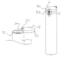
- FIG. 2 is a structural schematic view of an opened battery component, according to the first embodiment of the present application.
- FIG. 3 is a perspective view of the end cover in FIG. 2 ;
- FIG. 4 is a structural schematic view of a closed battery component, according to a second embodiment of the present application.
- FIG. 5 is an enlarged view of the area A in FIG. 4 ;
- FIG. 6 is a structural schematic view of a closed battery component, according to a third embodiment of the present application.
- FIG. 7 is a structural schematic view of a closed battery component, according to a fourth embodiment of the present application.
- a battery component and an electronic cigarette are provided here, aiming at following drawbacks: the complicated operation when changing the battery of an electronic cigarette in which a threaded connection structure is used to connect the end cover to the outer casing pipe; and the power leakage hidden danger caused by a loose fastening structure of the partially opened end cover when the end cover is opened too much times by using an end cover flipping technology.
- the battery component of the present application comprises a casing pipe used for accommodating a battery and an end cover that is arranged on and covers an open end of the casing pipe.
- the battery component further comprises a rotation mechanism used for connecting the casing pipe to the end cover.
- a center axis of the rotation mechanism is parallel to a central axis line of the casing pipe; and the end cover rotates about the center axis of the rotation mechanism so as to open or close the casing pipe.
- the end cover can be directly rotated to open the casing pipe, and the operation is simple.
- the center axis of the rotation mechanism is parallel to the central axis line of the casing pipe, and the end cover rotates about the center axis of the rotation mechanism so as to open or close the casing pipe; in this way, even when a connection structure on one side of the end cover facing the rotation mechanism fails, the end cover is not naturally opened because the radial space is very compact, overcoming a defect that reserved space exists in an axial direction of the electronic cigarette, which makes the end cover partially open and results in an existent of power leakage hidden danger exists, when a fastening structure in an end cover flipping technology fails.
- Embodiment 1 is a diagrammatic representation of Embodiment 1:
- FIG. 1 is a structural schematic view of a closed battery component, according to a first embodiment of the present application
- FIG. 2 is a structural schematic view of an opened battery component, according to a first embodiment of the present application
- FIG. 3 is a perspective view of the end cover in FIG. 2 .
- the battery component comprises a casing pipe 1 used for accommodating a battery and an end cover 2 that is arranged on and covers an open end of the casing pipe 1 ; wherein, the battery component further comprises a rotation mechanism 3 used for connecting the casing pipe 1 to the end cover 2 .
- a center axis of the rotation mechanism 3 is parallel to a central axis line of the casing pipe 1 ; and the end cover 2 rotates about the center axis of the rotation mechanism 3 so as to open or close the casing pipe 1 .
- the rotation mechanism 3 comprises a first connection portion and a second connection portion, and the first connection portion is connected to the second connection portion via a rotation shaft or a pin shaft.
- the first connection portion is preferably connected to the second connection portion via the rotation shaft.
- the first connection portion is a first flange; wherein the first flange is defined on a side edge of the open end of the casing pipe 1 and further extends radially along a direction away from a central axis of the casing pipe 1 .
- the second connection portion is a second flange 32 , wherein the second flange 32 is defined on a side edge of the end cover 2 and further extends along the same direction with the first flange.
- a first through hole is defined on the first flange, and a second through hole 321 right opposite the first through hole is defined on the second flange 32 .
- the rotation shaft successively passes through space respectively formed by the first through hole and the second through hole 321 .
- Limiting covers 33 are arranged on both ends of the rotation shaft, and are used for limiting an axial displacement of the end cover 2 .
- An elastic snap-fit connection structure 5 is arranged on another side opposite to the rotation mechanism 3 , and the elastic snap-fit connection structure 5 is used to form an elastic snap-fit connection between the end cover 2 and the casing pipe 1 .
- the elastic snap-fit connection structure 5 comprises at least one overhead part and at least one accommodating part matching with the overhead part; wherein the overhead part is defined on a peripheral wall surface of the casing pipe 1 or the end cover 2 , and the accommodating part is defined on the peripheral wall surface of end cover 2 or the casing pipe 1 .
- the overhead part is elastically arranged on the top inside the accommodating part.
- the overhead part is a bulge 51 while the accommodating part is a groove 52 .
- the locations of the bulge 51 and the groove 52 can be exchanged. That is, the bulge 51 is defined on the end cover 2 and the groove 52 is correspondingly defined on the open end of the casing pipe 1 .
- the bulge 51 must be deformed to a certain extent in order to be shifted from the groove 52 . Therefore, the bulge 51 is required to be elastic.
- the bulge 51 axially extends along a direction away from the open end of the casing pipe 1 in such a way that a gradient thereof gradually decreases.
- the bulge 51 can be replaced by an elastic piece.
- a tapered groove is defined between an inner wall and an outer wall of the casing pipe 1 .
- Two ends of the elastic piece are movably mounted inside the tapered groove.
- the end cover 2 When the end cover 2 is closed, an upward force is generated at two ends of the elastic piece because the elastic piece is bent in the middle. Therefore, the middle bent part of the elastic piece stretches out of the tapered groove and heads into the groove 52 , and the casing pipe is thereby closed.
- a force is applied to the end cover and a downward force is thereby generated to be pressed on the elastic piece.
- the middle bent part of the elastic piece is almost pressed into the tapered groove, and the casing pipe 1 is opened as a result.
- a circular groove 20 is defined in the middle of an end of the end cover 2 , and the end faces the casing pipe 1 .
- a radius of the circular groove 20 is equal to an inner diameter of the casing pipe 1 .
- a hollow circular truncated cone 21 used for abutting against the battery is defined on a bottom of the circular groove 20 and axially extends along a direction towards the casing pipe 1 .
- a contact piece 22 used for abutting against the battery is built into a recess where the circular truncated cone 21 is contacted with the battery.
- the contact piece 22 is a conductive metal sheet.
- a wire (not shown) used for electrically connected to the atomizing unit is fixedly connected to an end face of the contact piece 22 away from the battery.
- a through hole (not shown) is defined on a sidewall of the circular truncated cone 21 to draw forth the wire from the round table 21 . After being drawn forth via the through hole, the wire is axially drawn forth away from the end cover 2 via the space between the battery and casing pipe 1 .
- Embodiment 2 is a diagrammatic representation of Embodiment 1:
- FIG. 4 is a structural schematic view of a closed battery component according to a second embodiment of the present application
- FIG. 5 is an enlarged view of the area A in FIG. 4 .
- the overhead part is the telescopic rod 55 .
- a first mounting hole 53 is defined between an inner wall and an outer wall of the casing pipe 1 , and is further defined axially along the open end of the casing pipe 1 .
- the telescopic rod 55 is movably connected to an inside of the first mounting hole 53 .
- An elastic member 56 is fixed between the telescopic rod 55 and a bottom of the first mounting hole 53 .
- the accommodating part is a second mounting hole 54 defined on the end cover 2 and right opposite the first mounting hole 53 .
- the telescopic rod 55 is inserted into the second mounting hole 54 under an elastic force of the elastic member 56 ; while during the opening process of the end cover 2 and the casing pipe 1 , the telescopic rod 55 is pressed into the first mounting hole 53 .
- Embodiment 3 is a diagrammatic representation of Embodiment 3
- FIG. 6 is a structural schematic view of a closed battery component, according to a third embodiment of the present application.
- the difference between the third embodiment and the first and second embodiments is that the elastic snap-fit connection structure is not used, but a magnetic connection structure 4 is arranged on the end face of the casing pipe 1 and the end face is contacted with the end cover 2 .
- a first mounting hole is defined on the casing pipe 1 and a second mounting hole is defined on the end cover 2 , which is the same as in the second embodiment.
- Two magnets which are attracted by each other are respectively arranged on the first mounting hole and the second mounting hole.
- Embodiment 4 is a diagrammatic representation of Embodiment 4:
- FIG. 7 is a structural schematic view of a closed battery component, according to a fourth embodiment of the present application.
- the contact surface between the end cover and the casing pipe is level.
- the difference between the fourth embodiment and the above three embodiments is that the contact surface between the end cover and the casing pipe is curved.
- the connection structure arranged on another side opposite to the rotation mechanism can be any connection structure of the above-mentioned three embodiments, and a magnetic connection structure is preferred in this embodiment.
- An electronic cigarette which comprises an atomizing unit and the above-mentioned battery component.
- the atomizing unit is detachably connected to the battery component or the atomizing unit and the battery component are an integrally formed structure by sharing one outer casing pipe.
- One end of the above-mentioned battery component away from the end cover is electrically connected to the atomizing unit to power the atomizing unit.
- the end cover can be directly rotated to open the casing pipe; an operation is simple.
- the center axis of the rotation mechanism is parallel to the central axis line of the casing pipe, and the end cover rotates about the center axis of the rotation mechanism so as to open or close the casing pipe; in this way, even when a connection structure on one side of the end cover facing the rotation mechanism fails, the end cover is not naturally opened because the radial space is very compact, overcoming a defect that reserved space exists in an axial direction of the electronic cigarette which makes the end cover partially open and results in an existent of power leakage hidden danger exists, when a fastening structure in an end cover flipping technology fails.
Landscapes
- Chemical & Material Sciences (AREA)
- Chemical Kinetics & Catalysis (AREA)
- Electrochemistry (AREA)
- General Chemical & Material Sciences (AREA)
- Battery Mounting, Suspending (AREA)
Applications Claiming Priority (1)
| Application Number | Priority Date | Filing Date | Title |
|---|---|---|---|
| PCT/CN2013/082698 WO2015027473A1 (fr) | 2013-08-30 | 2013-08-30 | Élément de batterie et cigarette électronique |
Publications (2)
| Publication Number | Publication Date |
|---|---|
| US20160213061A1 US20160213061A1 (en) | 2016-07-28 |
| US9901115B2 true US9901115B2 (en) | 2018-02-27 |
Family
ID=52585428
Family Applications (1)
| Application Number | Title | Priority Date | Filing Date |
|---|---|---|---|
| US14/915,275 Expired - Fee Related US9901115B2 (en) | 2013-08-30 | 2013-08-30 | Battery component and electronic cigarette |
Country Status (2)
| Country | Link |
|---|---|
| US (1) | US9901115B2 (fr) |
| WO (1) | WO2015027473A1 (fr) |
Cited By (1)
| Publication number | Priority date | Publication date | Assignee | Title |
|---|---|---|---|---|
| US11522244B2 (en) * | 2018-09-12 | 2022-12-06 | Hong Kong Ivps International Limited | Power supply and electronic cigarette having same |
Families Citing this family (27)
| Publication number | Priority date | Publication date | Assignee | Title |
|---|---|---|---|---|
| US10244793B2 (en) | 2005-07-19 | 2019-04-02 | Juul Labs, Inc. | Devices for vaporization of a substance |
| US10279934B2 (en) | 2013-03-15 | 2019-05-07 | Juul Labs, Inc. | Fillable vaporizer cartridge and method of filling |
| US10512282B2 (en) | 2014-12-05 | 2019-12-24 | Juul Labs, Inc. | Calibrated dose control |
| US9901115B2 (en) * | 2013-08-30 | 2018-02-27 | Huizhou Kimree Technology Co., Ltd. Shenzhen Branch | Battery component and electronic cigarette |
| US10980273B2 (en) | 2013-11-12 | 2021-04-20 | VMR Products, LLC | Vaporizer, charger and methods of use |
| US10058129B2 (en) | 2013-12-23 | 2018-08-28 | Juul Labs, Inc. | Vaporization device systems and methods |
| US10076139B2 (en) | 2013-12-23 | 2018-09-18 | Juul Labs, Inc. | Vaporizer apparatus |
| PT3508080T (pt) | 2013-12-23 | 2021-03-02 | Juul Labs Int Inc | Sistemas e métodos de dispositivo de vaporização |
| US10159282B2 (en) | 2013-12-23 | 2018-12-25 | Juul Labs, Inc. | Cartridge for use with a vaporizer device |
| US20160366947A1 (en) | 2013-12-23 | 2016-12-22 | James Monsees | Vaporizer apparatus |
| USD825102S1 (en) | 2016-07-28 | 2018-08-07 | Juul Labs, Inc. | Vaporizer device with cartridge |
| USD842536S1 (en) | 2016-07-28 | 2019-03-05 | Juul Labs, Inc. | Vaporizer cartridge |
| USD802835S1 (en) * | 2015-02-20 | 2017-11-14 | Fontem Holdings 2 B.V. | Endcap for electronic cigarette |
| UA125687C2 (uk) | 2016-02-11 | 2022-05-18 | Джуул Лебз, Інк. | Заповнювальний картридж випарного пристрою та способи його заповнення |
| MX2018009703A (es) | 2016-02-11 | 2019-07-08 | Juul Labs Inc | Cartuchos de fijacion segura para dispositivos vaporizadores. |
| US10405582B2 (en) | 2016-03-10 | 2019-09-10 | Pax Labs, Inc. | Vaporization device with lip sensing |
| GB201605102D0 (en) | 2016-03-24 | 2016-05-11 | Nicoventures Holdings Ltd | Mechanical connector for electronic vapour provision system |
| USD849996S1 (en) | 2016-06-16 | 2019-05-28 | Pax Labs, Inc. | Vaporizer cartridge |
| USD836541S1 (en) | 2016-06-23 | 2018-12-25 | Pax Labs, Inc. | Charging device |
| USD851830S1 (en) | 2016-06-23 | 2019-06-18 | Pax Labs, Inc. | Combined vaporizer tamp and pick tool |
| KR102327122B1 (ko) | 2016-12-12 | 2021-11-16 | 브이엠알 프로덕츠 엘엘씨 | 기화기 카트리지 |
| CN206909706U (zh) * | 2017-05-08 | 2018-01-23 | 深圳市艾维普思科技股份有限公司 | 雾化器及电子烟 |
| EP3639682A4 (fr) * | 2017-06-12 | 2021-03-03 | Changzhou Patent Electronic Technology Co., Ltd | Atomiseur et cigarette électronique l'utilisant |
| CN107319968A (zh) * | 2017-07-17 | 2017-11-07 | 任安印 | 一种翻盖式真空破壁机 |
| USD887632S1 (en) | 2017-09-14 | 2020-06-16 | Pax Labs, Inc. | Vaporizer cartridge |
| CN110710729B (zh) * | 2019-08-27 | 2022-12-20 | 深圳市合元科技有限公司 | 气雾生成装置 |
| CN112545056A (zh) * | 2020-11-16 | 2021-03-26 | 深圳市吉迩科技有限公司 | 一种雾化芯锁止方法及其装置、气溶胶产生装置 |
Citations (14)
| Publication number | Priority date | Publication date | Assignee | Title |
|---|---|---|---|---|
| US1332482A (en) * | 1919-03-10 | 1920-03-02 | Charles J Baker | Battery-terminal connector |
| US4083011A (en) * | 1976-07-26 | 1978-04-04 | General Electric Company | Battery holder and connector for a radio receiver or the like |
| US20020047237A1 (en) * | 1998-08-04 | 2002-04-25 | Satoshi Oshita | Lcd game apparatus |
| US20100124695A1 (en) * | 2008-11-14 | 2010-05-20 | Shenzhen Futaihong Precision Industry Co., Ltd. | Battery assembly for portable electronic device |
| US20100321868A1 (en) * | 2009-06-22 | 2010-12-23 | Fih (Hong Kong) Limited | Battery cover assembly for portable electronic device |
| US20110008663A1 (en) * | 2009-07-07 | 2011-01-13 | Hong Fu Jin Precision Industry (Shenzhen) Co., Ltd. | Fixing mechanism and electronic device using same |
| US20110064982A1 (en) * | 2009-09-14 | 2011-03-17 | Hong Fu Jin Precision Industry (Shenzhen) Co., Ltd. | Fixing mechanism |
| US20110091757A1 (en) * | 2009-10-19 | 2011-04-21 | Hong Fu Jin Precision Industry (Shenzhen) Co., Ltd | Fixing mechanism |
| CN202566290U (zh) | 2012-05-10 | 2012-12-05 | 卓尔悦(常州)电子科技有限公司 | 供电装置及电子烟 |
| US20130081642A1 (en) * | 2011-09-29 | 2013-04-04 | Robert Safari | Cartomizer E-Cigarette |
| US20130164591A1 (en) * | 2011-12-22 | 2013-06-27 | Chia-Cheng Su | Portable electronic apparatus and removable battery case therefor |
| US20130213418A1 (en) * | 2012-02-22 | 2013-08-22 | Altria Client Services Inc. | Electronic smoking article |
| US20140182609A1 (en) * | 2012-12-28 | 2014-07-03 | Qiuming Liu | Electronic cigarette |
| US20160213061A1 (en) * | 2013-08-30 | 2016-07-28 | Kimree Hi-Tech Inc. | Battery component and electronic cigarette |
Family Cites Families (2)
| Publication number | Priority date | Publication date | Assignee | Title |
|---|---|---|---|---|
| CN202749479U (zh) * | 2012-08-23 | 2013-02-20 | 卓尔悦(常州)电子科技有限公司 | 电子烟可调电压电池 |
| CN203398175U (zh) * | 2013-08-30 | 2014-01-15 | 刘秋明 | 电池组件以及电子烟 |
-
2013
- 2013-08-30 US US14/915,275 patent/US9901115B2/en not_active Expired - Fee Related
- 2013-08-30 WO PCT/CN2013/082698 patent/WO2015027473A1/fr active Application Filing
Patent Citations (15)
| Publication number | Priority date | Publication date | Assignee | Title |
|---|---|---|---|---|
| US1332482A (en) * | 1919-03-10 | 1920-03-02 | Charles J Baker | Battery-terminal connector |
| US4083011A (en) * | 1976-07-26 | 1978-04-04 | General Electric Company | Battery holder and connector for a radio receiver or the like |
| US20020047237A1 (en) * | 1998-08-04 | 2002-04-25 | Satoshi Oshita | Lcd game apparatus |
| US20100124695A1 (en) * | 2008-11-14 | 2010-05-20 | Shenzhen Futaihong Precision Industry Co., Ltd. | Battery assembly for portable electronic device |
| US20100321868A1 (en) * | 2009-06-22 | 2010-12-23 | Fih (Hong Kong) Limited | Battery cover assembly for portable electronic device |
| CN101931063A (zh) | 2009-06-22 | 2010-12-29 | 深圳富泰宏精密工业有限公司 | 电池盖结构 |
| US20110008663A1 (en) * | 2009-07-07 | 2011-01-13 | Hong Fu Jin Precision Industry (Shenzhen) Co., Ltd. | Fixing mechanism and electronic device using same |
| US20110064982A1 (en) * | 2009-09-14 | 2011-03-17 | Hong Fu Jin Precision Industry (Shenzhen) Co., Ltd. | Fixing mechanism |
| US20110091757A1 (en) * | 2009-10-19 | 2011-04-21 | Hong Fu Jin Precision Industry (Shenzhen) Co., Ltd | Fixing mechanism |
| US20130081642A1 (en) * | 2011-09-29 | 2013-04-04 | Robert Safari | Cartomizer E-Cigarette |
| US20130164591A1 (en) * | 2011-12-22 | 2013-06-27 | Chia-Cheng Su | Portable electronic apparatus and removable battery case therefor |
| US20130213418A1 (en) * | 2012-02-22 | 2013-08-22 | Altria Client Services Inc. | Electronic smoking article |
| CN202566290U (zh) | 2012-05-10 | 2012-12-05 | 卓尔悦(常州)电子科技有限公司 | 供电装置及电子烟 |
| US20140182609A1 (en) * | 2012-12-28 | 2014-07-03 | Qiuming Liu | Electronic cigarette |
| US20160213061A1 (en) * | 2013-08-30 | 2016-07-28 | Kimree Hi-Tech Inc. | Battery component and electronic cigarette |
Non-Patent Citations (1)
| Title |
|---|
| International Search Report of PCT Patent Application No. PCT/CN2013/082698 dated Jun. 10, 2014. |
Cited By (1)
| Publication number | Priority date | Publication date | Assignee | Title |
|---|---|---|---|---|
| US11522244B2 (en) * | 2018-09-12 | 2022-12-06 | Hong Kong Ivps International Limited | Power supply and electronic cigarette having same |
Also Published As
| Publication number | Publication date |
|---|---|
| US20160213061A1 (en) | 2016-07-28 |
| WO2015027473A1 (fr) | 2015-03-05 |
Similar Documents
| Publication | Publication Date | Title |
|---|---|---|
| US9901115B2 (en) | Battery component and electronic cigarette | |
| WO2015072298A1 (fr) | Structure pour l'ouverture et la fermeture d'un orifice d'alimentation en carburant | |
| CN102331142A (zh) | 冰箱门装置及冰箱 | |
| KR102489300B1 (ko) | 캔부재 및 이를 포함하는 로터 조립체 | |
| CN106663988A (zh) | 电动机以及换气扇 | |
| JP6379365B2 (ja) | 電気機器収納用箱 | |
| CN107476992B (zh) | 送风装置 | |
| JP2008229500A5 (fr) | ||
| TW201318513A (zh) | 扭簧及使用該扭簧的掀蓋式設備 | |
| KR20170048692A (ko) | 수도꼭지의 스핀들과 디스크 결합구조 | |
| KR101122362B1 (ko) | 착탈이 가능한 회전코드를 갖는 미용기구 | |
| CN103673474A (zh) | 电源线固定装置及包括其的冰箱 | |
| KR101650535B1 (ko) | 케이블 정리구 | |
| CN101969106A (zh) | 固定结构 | |
| CN208637707U (zh) | 一种延长线插座 | |
| CN204460109U (zh) | 不松动的灯具座 | |
| US20130067735A1 (en) | Device to facilitate the assembly and fixation of a junction box in an electrical engine | |
| KR102542026B1 (ko) | 에어로졸 생성 장치 | |
| JP2008309242A (ja) | チルトヒンジ | |
| CN105624980A (zh) | 旋钮、使用该旋钮的家用电器及旋钮的安装方法 | |
| CN209471393U (zh) | 用于磁控旋钮的壳底盖、磁控旋钮以及电器设备 | |
| CN208657224U (zh) | 一种电控柜元件安装架 | |
| JP5691957B2 (ja) | 電線カバー | |
| JP6226720B2 (ja) | ロータリーダンパ | |
| CN107249270A (zh) | 一种用于电器箱柜的铰接结构 |
Legal Events
| Date | Code | Title | Description |
|---|---|---|---|
| AS | Assignment |
Owner name: KIMREE HI-TECH INC., VIRGIN ISLANDS, BRITISH Free format text: ASSIGNMENT OF ASSIGNORS INTEREST;ASSIGNOR:LIU, QIUMING;REEL/FRAME:037856/0183 Effective date: 20160229 |
|
| AS | Assignment |
Owner name: HUIZHOU KIMREE TECHNOLOGY CO., LTD. SHENZHEN BRANC Free format text: ASSIGNMENT OF ASSIGNORS INTEREST;ASSIGNOR:KIMREE HI-TECH INC.;REEL/FRAME:044087/0351 Effective date: 20171110 |
|
| STCF | Information on status: patent grant |
Free format text: PATENTED CASE |
|
| FEPP | Fee payment procedure |
Free format text: MAINTENANCE FEE REMINDER MAILED (ORIGINAL EVENT CODE: REM.); ENTITY STATUS OF PATENT OWNER: SMALL ENTITY |
|
| LAPS | Lapse for failure to pay maintenance fees |
Free format text: PATENT EXPIRED FOR FAILURE TO PAY MAINTENANCE FEES (ORIGINAL EVENT CODE: EXP.); ENTITY STATUS OF PATENT OWNER: SMALL ENTITY |
|
| STCH | Information on status: patent discontinuation |
Free format text: PATENT EXPIRED DUE TO NONPAYMENT OF MAINTENANCE FEES UNDER 37 CFR 1.362 |
|
| FP | Lapsed due to failure to pay maintenance fee |
Effective date: 20220227 |