US9864185B2 - Three-dimensional-endoscope optical system - Google Patents
Three-dimensional-endoscope optical system Download PDFInfo
- Publication number
- US9864185B2 US9864185B2 US14/190,666 US201414190666A US9864185B2 US 9864185 B2 US9864185 B2 US 9864185B2 US 201414190666 A US201414190666 A US 201414190666A US 9864185 B2 US9864185 B2 US 9864185B2
- Authority
- US
- United States
- Prior art keywords
- optical
- dimensional
- axes
- endoscope
- optical system
- Prior art date
- Legal status (The legal status is an assumption and is not a legal conclusion. Google has not performed a legal analysis and makes no representation as to the accuracy of the status listed.)
- Active, expires
Links
Images


Classifications
-
- G—PHYSICS
- G02—OPTICS
- G02B—OPTICAL ELEMENTS, SYSTEMS OR APPARATUS
- G02B23/00—Telescopes, e.g. binoculars; Periscopes; Instruments for viewing the inside of hollow bodies; Viewfinders; Optical aiming or sighting devices
- G02B23/24—Instruments or systems for viewing the inside of hollow bodies, e.g. fibrescopes
- G02B23/2407—Optical details
- G02B23/2415—Stereoscopic endoscopes
-
- A—HUMAN NECESSITIES
- A61—MEDICAL OR VETERINARY SCIENCE; HYGIENE
- A61B—DIAGNOSIS; SURGERY; IDENTIFICATION
- A61B1/00—Instruments for performing medical examinations of the interior of cavities or tubes of the body by visual or photographical inspection, e.g. endoscopes; Illuminating arrangements therefor
- A61B1/00163—Optical arrangements
- A61B1/00193—Optical arrangements adapted for stereoscopic vision
-
- A—HUMAN NECESSITIES
- A61—MEDICAL OR VETERINARY SCIENCE; HYGIENE
- A61B—DIAGNOSIS; SURGERY; IDENTIFICATION
- A61B1/00—Instruments for performing medical examinations of the interior of cavities or tubes of the body by visual or photographical inspection, e.g. endoscopes; Illuminating arrangements therefor
- A61B1/00163—Optical arrangements
- A61B1/00194—Optical arrangements adapted for three-dimensional imaging
-
- G—PHYSICS
- G02—OPTICS
- G02B—OPTICAL ELEMENTS, SYSTEMS OR APPARATUS
- G02B13/00—Optical objectives specially designed for the purposes specified below
- G02B13/04—Reversed telephoto objectives
-
- G—PHYSICS
- G02—OPTICS
- G02B—OPTICAL ELEMENTS, SYSTEMS OR APPARATUS
- G02B23/00—Telescopes, e.g. binoculars; Periscopes; Instruments for viewing the inside of hollow bodies; Viewfinders; Optical aiming or sighting devices
- G02B23/24—Instruments or systems for viewing the inside of hollow bodies, e.g. fibrescopes
- G02B23/2407—Optical details
- G02B23/2423—Optical details of the distal end
- G02B23/243—Objectives for endoscopes
Definitions
- the present invention relates to a three-dimensional-endoscope optical system.
- Patent Literature 1 there are known three-dimensional observation systems (for example, see Patent Literature 1).
- the present invention provides a three-dimensional-endoscope optical system with which it is possible to perform observation with easy viewing and a three-dimensional effect, when observing a wide-angle observation area.
- the present invention provides the following solutions.
- An aspect of the present invention is a three-dimensional-endoscope optical system including two objective optical systems having optical axes that are arranged with a spacing therebetween; two lens groups that are disposed with a spacing therebetween in an optical-axis direction and that are disposed so as to be decentered relative to each other; and an optical-axis deflecting member that is disposed between the two lens groups and that deflects light that has passed through one of the two lens groups so as to make the light enter the other of the two lens group, wherein two optical images are simultaneously formed in a same plane, and the following conditions are satisfied: 0.5 mm ⁇ OP ⁇ 1.5 mm (1); 3 mm ⁇ D ⁇ 200 mm (2); ⁇ 10° (3); and 110° ⁇ 180° (4), where OP is a spacing between the optical axes of optical members at the most distal ends of the objective optical systems, D is a depth of field, ⁇ is an angle of convergence (inward angle) of the depth of field D when performing near-point observation, and ⁇ is an angle of view of
- FIG. 1 is a diagram showing a three-dimensional-endoscope optical system according to a first embodiment of the present invention.
- FIG. 2 is a diagram showing a three-dimensional-endoscope optical system according to a second embodiment of the present invention.
- FIG. 3 is a diagram showing a modification of the three-dimensional-endoscope optical system in FIG. 2 .
- FIG. 4 is a diagram showing a modification of the three-dimensional-endoscope optical system in FIG. 3 .
- FIG. 5 is a diagram showing a three-dimensional-endoscope optical system according to a third embodiment of the present invention.
- FIG. 6 is a diagram showing a three-dimensional-endoscope optical system according to a modification of the third embodiment of the present invention.
- FIG. 7 is a diagram showing an Example of the three-dimensional-endoscope optical system in FIG. 1 .
- FIG. 8 is a diagram showing an Example of the three-dimensional-endoscope optical system in FIG. 2 .
- FIG. 9 is a diagram showing an Example of the three-dimensional-endoscope optical system in FIG. 3 .
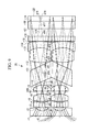
- FIG. 10 is a diagram showing Example 1 of the three-dimensional-endoscope optical system in FIG. 5 .
- FIG. 11 is a diagram showing, in ( a ) to ( c ), lateral aberrations of the three-dimensional-endoscope optical system in FIG. 10 .
- FIG. 12 is a diagram showing, in ( a ) to ( c ), lateral aberrations of the three-dimensional-endoscope optical system in FIG. 10 .
- FIG. 13 is a diagram showing, in ( a ) to ( c ), lateral aberrations of the three-dimensional-endoscope optical system in FIG. 10 .
- FIG. 14 is a diagram showing Example 2 of the three-dimensional-endoscope optical system in FIG. 6 .
- FIG. 15 is a diagram showing, in ( a ) to ( c ), lateral aberrations of the three-dimensional-endoscope optical system in FIG. 14 .
- FIG. 16 is a diagram showing, in ( a ) to ( c ), lateral aberrations of the three-dimensional-endoscope optical system in FIG. 14 .
- FIG. 17 is a diagram showing, in ( a ) to ( c ), lateral aberrations of the three-dimensional-endoscope optical system in FIG. 14 .
- FIG. 18 is a diagram showing Example 3 of the three-dimensional-endoscope optical system in FIG. 5 .
- FIG. 19 is a diagram showing, in ( a ) to ( c ), lateral aberrations of the three-dimensional-endoscope optical system in FIG. 18 .
- FIG. 20 is a diagram showing, in ( a ) to ( c ), lateral aberrations of the three-dimensional-endoscope optical system in FIG. 18 .
- FIG. 21 is a diagram showing, in ( a ) to ( c ), lateral aberrations of the three-dimensional-endoscope optical system in FIG. 18 .
- a three-dimensional-endoscope optical system 1 according to a first embodiment of the present invention will be described below with reference to the drawings.
- the three-dimensional-endoscope optical system 1 is provided with two objective optical systems 2 and 3 that are arranged side-by-side along two optical axes 2 a and 3 a disposed parallel to each other with a spacing therebetween.
- Each of the objective optical systems 2 and 3 is constituted of, sequentially from the object side, a plano-concave lens 4 whose flat surface 4 a is disposed on the object side, a flare diaphragm 5 , a plano-convex lens 7 whose convex surface 7 a is disposed on the object side, a meniscus lens 8 whose concave surface 8 a is disposed on the object side, an aperture stop 9 , a combined lens 13 formed of a biconvex lens 11 and a meniscus lens 12 , a flat-parallel plate 14 , a plano-convex lens 15 whose convex surface 15 a is disposed on the object side, and a flat-parallel plate 16 .
- An end surface 16 a of the flat-parallel plate 16 serves as an image forming position where an optical image of the object is formed, and an imaging surface of an imaging device (not shown), such as a CCD or the like, is disposed at this position.
- Two beams that form two optical images independently pass through the individual objective optical systems 2 and 3 without intersecting each other. Also, because two optical images are formed side-by-side at the position of the end surface 16 a of the flat-parallel plate 16 , by disposing a single imaging device at this position, the two optical images can be captured at the same time.
- the two objective optical systems 2 and 3 satisfy the following Conditional Expressions: 0.5 mm ⁇ OP ⁇ 1.5 mm (1); 3 mm ⁇ D ⁇ 200 mm (2); ⁇ 10° (3); and 110° ⁇ 180° (4), where OP is a spacing between the optical axes 2 a and 3 a of the plano-concave lenses 4 , which are optical members at the most distal ends of the objective optical systems 2 and 3 , D is a depth of field, ⁇ is an angle of convergence (inward angle) of the depth of field D when performing near-point observation, and ⁇ is an angle of view of the objective optical systems 2 and 3 .
- an appropriate level of three-dimensional effect can be achieved by satisfying Expression (1).
- a problem tends to occur in that the three-dimensional effect would be lost if the spacing between the optical axes is equal to or less than 0.5 mm, and that the three-dimensional effect would be too strong if the spacing is equal to or greater than 1.5 mm, which nauseates an observer; however, such a problem does not occur when Expression (1) is satisfied.
- an appropriate level of depth of field D can be achieved by satisfying Expression (2).
- a problem tends to occur in that the three-dimensional effect would be too strong if the depth of field D is equal to or less than 3 mm, which causes eye fatigue in the observer, and that the three-dimensional effect would be lost if the depth of field D is equal to or greater than 200 mm, which makes three-dimensional imaging difficult; however, such a problem does not occur when Expression (2) is satisfied.
- the optical axes 2 a and 3 a of the two objective optical systems 2 and 3 are arranged in parallel to each other, there is an advantage in that, in the images of the two optical images acquired when the same object is captured, it is possible to suppress the occurrence of vertical displacement and horizontal displacement at peripheral portions of the images.
- each of two objective optical systems 21 and 22 is provided with two lens groups 23 A and 23 B that are arranged with a spacing therebetween in the direction along an optical axis 21 a or 22 a , and an optical-axis deflecting member 24 that is disposed between these lens groups 23 A and 23 B.
- the lens group 23 A on the object side is constituted of, sequentially from the object side, a plano-concave lens 25 whose flat surface 25 a is disposed on the object side, a meniscus lens 26 whose convex surface 26 a is disposed on the object side, a biconvex lens 27 , and a meniscus lens 28 whose concave surface 28 a is disposed on the object side.
- the lens group 23 B on the image side is constituted of, sequentially from the object side, a combined lens 31 formed of a biconvex lens 29 and a meniscus lens 30 , and three flat-parallel plates 32 , 33 , and 34 .
- the optical-axis deflecting members 24 are glass flat-parallel plates that are disposed inclined with respect to the optical axes 21 a and 22 a . Accordingly, beams that have passed through the lens groups 23 A on the object side are deflected twice by entrance surfaces 24 a and exit surfaces 24 b of the optical-axis deflecting members 24 , thus exiting therefrom in directions parallel to the entering directions. In the example shown in FIG.
- the inclination directions of the optical-axis deflecting members 24 are set so that the optical axes 21 a and 22 a at the plano-concave lenses 25 , which are the optical members at the most distal ends, and the optical axes 21 a and 22 a of the two beams at the image position are maintained parallel to each other, and so that the spacing between the optical axes 21 a and 22 a becomes smaller on the image side than on the object side.
- the optical axes 21 a and 22 a can be deflected in a simple manner.
- the three-dimensional-endoscope optical system 20 by increasing the spacing between the optical axes 21 a and 22 a at the plano-concave lenses 25 , which are the optical members at the most distal ends, it is possible to achieve a sufficient three-dimensional effect, and, by decreasing the spacing between the optical axes 21 a and 22 a at the image position, it is also possible to form images of the two optical images on a small imaging device.
- optical-axis deflecting members 24 it is possible to make the individual beams pass through near the centers of the optical axes 21 a and 22 a of the individual lens groups 23 A and 23 B, and it is possible to perform three-dimensional observation by using clear images in which the occurrence of aberrations is suppressed.
- image formation of the two images can be achieved within a small area while avoiding interference between the two objective optical systems with each other, even if the spacing between the optical axes of the optical members at the most distal ends is small, and thus, it is possible to capture images with a single imaging device, or it is possible to reduce the size of the imaging device.
- the optical-axis deflecting members 24 are disposed so that the spacing between the optical axes 21 a and 22 a on the image side becomes smaller than the spacing between the optical axes 21 a and 22 a on the object side, alternatively, the optical-axis deflecting members 24 may be disposed so that the spacing between the optical axes 21 a and 22 a on the image side becomes greater than the spacing between the optical axes 21 a and 22 a on the object side.
- the optical members that are sufficiently close to each other may be formed as single units so as to serve as shared optical members between the left and right objective optical systems 21 and 22 , and thus, interference between the optical members with each other may be avoided.
- the beams that enter the plano-concave lenses 25 and that form the two optical images can be made to intersect each other inside the plano-concave lenses 25 .
- a blocking member 35 that has a certain thickness in the optical-axis direction and that has through-holes 35 a that make the beams that form the two optical images pass through separately, as shown in FIG. 4 . By doing so, the beams that form images at positions that overlap with each other are blocked by the blocking member 35 , and thus, it is possible to prevent the images from overlapping.
- the three-dimensional-endoscope optical system 40 according to this embodiment differs from the second embodiment in that, as shown in FIG. 5 , optical-axis deflecting members 124 formed of wedge-shaped wedge prisms are provided instead of the optical-axis deflecting members 24 formed of the glass flat-parallel plates.
- the optical-axis deflecting members 124 are provided between the lens groups 23 A and 23 B and have entrance surfaces 124 a and exit surfaces 124 b that are disposed inclined at different angles from each other with respect to the optical axes of these lens groups 23 A and 23 B. Accordingly, beams that have passed through the lens groups 23 A on the object side are deflected twice by the entrance surfaces 124 a and the exit surfaces 124 b of the optical-axis deflecting members 124 , thus exiting therefrom in directions differing from the entering directions.
- the optical axes 21 a and 22 a can be deflected in a simple manner.
- the individual optical-axis deflecting members 124 of the individual objective optical systems 2 and 3 are disposed in an orientation in which ends whose thicknesses are greater are placed on the sides that abut each other, and other ends whose thicknesses are smaller are placed on the sides that are away from each other.
- inclination angles of the entrance surfaces 124 a and the exit surfaces 124 b of the optical-axis deflecting members 124 are set so that the optical axes 21 a and 22 a at the plano-concave lenses 25 , which are the optical members at the most distal ends, and the optical axes 21 a and 22 a of the two beams at the image position have different angles, and the spacing between the optical axes 21 a and 22 a becomes smaller on the image side than on the object side.
- a light-blocking member 135 that makes beams pass separately through the objective optical systems 21 and 22 is disposed between the two optical axes 2 a and 3 a of the objective optical systems 21 and 22 .
- the light-blocking member 135 is disposed along the optical-axis direction in, for example, an area from the entrance surfaces 124 a of the optical-axis deflecting members 124 to convex surfaces 15 a of plano-convex lenses 15 .
- all optical members constituting the individual objective optical systems 21 and 22 individually have entrance surfaces and exit surfaces that are rotationally symmetrical about the same rotational symmetry axis.
- front and rear surfaces of the optical-axis deflecting members 124 that is, entrance surfaces 124 a and exit surfaces 124 b thereof, have a free-form surface.
- the shape of free-form surface FFS is defined by the following Expression (a). Note that the Z-axis in this defining expression would be the axis of the free-form surface FFS. In addition, coefficients not included in the data are 0.
- the first term of Expression (a) is a spherical term, and the second term thereof is a free-form surface term.
- R is the radius of curvature of the apex
- the free-form surface term is defined as follows:
- C j (j is an integer equal to or greater than 1) are coefficients.
- the decentering direction indicates decentering in the X-Z plane
- the plane of symmetry of the free-form surface is the X-Z plane.
- the same advantages are afforded as the three-dimensional-endoscope optical system 1 according to the first embodiment and the three-dimensional-endoscope optical system 20 according to the second embodiment.
- the light-blocking member 135 it is possible to prevent the beams that form the two optical images from overlapping at the optical-image position, and thus, it is possible to prevent crosstalk between the left and right images.
- the three-dimensional-endoscope optical system 40 has been described in terms of an example employing the optical-axis deflecting members 124 that make the spacing between the optical axes 21 a and 22 a on the image side smaller than the spacing between the optical axes 21 a and 22 a on the object side, alternatively, it is permissible to employ optical-axis deflecting members 124 formed of wedge prisms that make the spacing between the optical axes 21 a and 22 a on the image side greater than the spacing between the optical axes 21 a and 22 a on the object side.
- the individual optical-axis deflecting members 124 of the individual objective optical systems 2 and 3 should be disposed with respect to each other in an orientation in which ends whose thicknesses are smaller are placed on the sides that abut each other, and other ends whose thicknesses are greater are placed on the sides that are away from each other.
- the light-blocking member 135 is disposed along the optical-axis direction in an area from the object-side surfaces of the biconvex lenses 29 to the convex surfaces 15 a of the plano-convex lenses 15 .
- the optical members that are sufficiently close to each other may be formed as single units so as to serve as shared optical members between the left and right objective optical systems 21 and 22 , and thus, interference between the optical members with each other may be avoided.
- the light-blocking member 135 is disposed between the two optical axes 2 a and 3 a of the objective optical systems 21 and 22 ; however, it is permissible not to employ the light-blocking member 135 .
- FIG. 7 is a diagram showing the lens arrangement of the three-dimensional-endoscope optical system 1 according to this Example, Table 1 shows lens data thereof, and Table 2 shows various data, including values for Conditional Expressions (1) to (4). All of Conditional Expressions (1) to (4) are satisfied in this Example.
- FIG. 8 is a diagram showing a first lens arrangement of the three-dimensional-endoscope optical system 20 according to this Example, Table 3 shows lens data thereof, and Table 4 shows various data, including values for Conditional Expressions (1) to (4). All of Conditional Expressions (1) to (4) are satisfied in this Example.
- FIG. 9 is a diagram showing a second lens arrangement of the three-dimensional-endoscope optical system 20 according to this Example, Table 5 shows lens data thereof, and Table 6 shows various data, including values for Conditional Expressions (1) to (4). All of Conditional Expressions (1) to (4) are satisfied in this Example.
- Example 1 of the three-dimensional-endoscope optical system 40 according to the third embodiment of the present invention will be described.
- FIG. 10 is a diagram showing a first lens arrangement of the three-dimensional-endoscope optical system 40 according to this Example, and FIG. 11( a ) to ( c ) , FIG. 12( a ) to ( c ) , and FIG. 13( a ) to ( c ) show lateral aberrations related to this Example.
- FIG. 11( a ) to ( c ) , FIG. 12( a ) to ( c ) , and FIG. 13( a ) to ( c ) broken lines indicate 656.2725 NM, solid lines indicate 587.5618 NM, and one-dot-chain lines indicate 486.1327 NM. This is the same in FIG.
- Table 7 shows lens data and Table 8 shows various data, including values for Conditional Expressions (1) to (4). All of Conditional Expressions (1) to (4) are satisfied in this Example.
- Example 2 of the three-dimensional-endoscope optical system 40 according to this embodiment will be described.
- FIG. 14 is a diagram showing a first lens arrangement of the three-dimensional-endoscope optical system 40 according to this Example, FIG. 15( a ) to ( c ) , FIG. 16( a ) to ( c ) , and FIG. 17( a ) to ( c ) individually show lateral aberrations related to this Example, and Table 9 shows lens data thereof.
- Table 9 shows lens data thereof.
- Example 3 of the three-dimensional-endoscope optical system 40 according to this embodiment will be described.
- FIG. 18 is a diagram showing a first lens arrangement of the three-dimensional-endoscope optical system 40 according to this Example, FIG. 19( a ) to ( c ) , FIG. 20( a ) to ( c ) , and FIG. 21( a ) to ( c ) individually show lateral aberrations related to this Example, and Table 10 shows lens data thereof.
- Table 10 shows lens data thereof.
- the plane of the drawing is assumed to be the X-Z plane
- the direction pointing to the first surface from the object is assumed to be the Z-axis positive direction
- the direction in which the two optical axes 2 a and 3 a are arranged is assumed to be the X-axis direction
- the direction pointing to the front side from the back side of the plane of the drawing in FIGS. 10, 14, and 18 is assumed to be the Y-axis positive direction.
- decentering occurs in the X-Z plane
- the plane of symmetry of the free-form surface is the X-Z plane.
- the decentering surfaces are given decentering levels (X-axis direction, Y-axis direction, and Z-axis direction are indicated as X, Y, and Z, respectively) from the center of the origin of the above-described optical systems in the coordinate systems in which these surfaces are defined and inclination angles ( ⁇ , ⁇ , and ⁇ (°), respectively) in the coordinate systems that define the individual surfaces respectively centered on the X-axis, Y-axis, and Z-axis of the coordinate systems defined by the origin of the optical systems.
- positive values of ⁇ and ⁇ indicate counterclockwise directions with respect to the positive direction of the respective axes
- positive values of ⁇ indicate clockwise directions with respect to the positive direction of the Z-axis.
- center axes of surfaces are rotated by ⁇ , ⁇ , and ⁇ in such a way that, first, the coordinate systems that define the individual surfaces are rotated counterclockwise by an amount indicated by ⁇ about the X-axis of the coordinate system defined by the origin of the optical systems; next, counterclockwise rotation is performed by an amount indicated by ⁇ about the Y-axis of this rotated new coordinate system; and then, clockwise rotation is performed by an amount indicated by ⁇ about Z-axis of this further rotated new coordinate system.
Landscapes
- Physics & Mathematics (AREA)
- Health & Medical Sciences (AREA)
- Optics & Photonics (AREA)
- Life Sciences & Earth Sciences (AREA)
- Surgery (AREA)
- General Physics & Mathematics (AREA)
- General Health & Medical Sciences (AREA)
- Radiology & Medical Imaging (AREA)
- Astronomy & Astrophysics (AREA)
- Nuclear Medicine, Radiotherapy & Molecular Imaging (AREA)
- Public Health (AREA)
- Heart & Thoracic Surgery (AREA)
- Medical Informatics (AREA)
- Molecular Biology (AREA)
- Animal Behavior & Ethology (AREA)
- Engineering & Computer Science (AREA)
- Biomedical Technology (AREA)
- Veterinary Medicine (AREA)
- Pathology (AREA)
- Biophysics (AREA)
- Instruments For Viewing The Inside Of Hollow Bodies (AREA)
- Lenses (AREA)
- Endoscopes (AREA)
Applications Claiming Priority (5)
| Application Number | Priority Date | Filing Date | Title |
|---|---|---|---|
| JP2012-007964 | 2012-01-18 | ||
| JP2012007964 | 2012-01-18 | ||
| JP2012-163042 | 2012-07-23 | ||
| JP2012163042 | 2012-07-23 | ||
| PCT/JP2012/081490 WO2013108500A1 (ja) | 2012-01-18 | 2012-12-05 | 立体視内視鏡用光学系 |
Related Parent Applications (1)
| Application Number | Title | Priority Date | Filing Date |
|---|---|---|---|
| PCT/JP2012/081490 Continuation WO2013108500A1 (ja) | 2012-01-18 | 2012-12-05 | 立体視内視鏡用光学系 |
Publications (2)
| Publication Number | Publication Date |
|---|---|
| US20140177043A1 US20140177043A1 (en) | 2014-06-26 |
| US9864185B2 true US9864185B2 (en) | 2018-01-09 |
Family
ID=48798937
Family Applications (1)
| Application Number | Title | Priority Date | Filing Date |
|---|---|---|---|
| US14/190,666 Active 2034-01-11 US9864185B2 (en) | 2012-01-18 | 2014-02-26 | Three-dimensional-endoscope optical system |
Country Status (5)
| Country | Link |
|---|---|
| US (1) | US9864185B2 (ja) |
| EP (1) | EP2806301A4 (ja) |
| JP (1) | JP5427323B2 (ja) |
| CN (1) | CN103782215B (ja) |
| WO (1) | WO2013108500A1 (ja) |
Cited By (1)
| Publication number | Priority date | Publication date | Assignee | Title |
|---|---|---|---|---|
| US20170014030A1 (en) * | 2014-03-07 | 2017-01-19 | Siemens Aktiengesellschaft | Endoscope Featuring Depth Ascertainment |
Families Citing this family (15)
| Publication number | Priority date | Publication date | Assignee | Title |
|---|---|---|---|---|
| EP3957229A1 (en) * | 2012-07-13 | 2022-02-23 | Steris Instrument Management Services, Inc. | Stereo endoscope system |
| JP6280749B2 (ja) * | 2013-01-23 | 2018-02-14 | オリンパス株式会社 | 光学系、立体撮像装置、及び内視鏡 |
| DE102013209956A1 (de) * | 2013-05-28 | 2014-12-04 | Xion Gmbh | Videoendoskopische Vorrichtung |
| JP6280803B2 (ja) * | 2014-04-24 | 2018-02-14 | オリンパス株式会社 | 立体撮像用光学系、立体撮像装置、及び内視鏡 |
| CN104049356B (zh) * | 2014-06-09 | 2016-09-14 | 中国航天科工集团第三研究院第八三五八研究所 | 包括平凹透镜的双目立体内窥镜体视物镜光学系统 |
| US9746660B2 (en) * | 2015-03-11 | 2017-08-29 | Lucida Research Llc | Binocular telescope with controlled parallax |
| JP6072392B1 (ja) * | 2015-03-30 | 2017-02-01 | オリンパス株式会社 | 内視鏡装置 |
| US11131860B1 (en) * | 2015-09-14 | 2021-09-28 | Wavefront Research, Inc. | Wide spatial field optical systems |
| CN108369369B (zh) | 2015-12-14 | 2020-11-17 | 奥林巴斯株式会社 | 摄像装置 |
| JPWO2017187814A1 (ja) * | 2016-04-25 | 2018-05-10 | オリンパス株式会社 | 内視鏡対物光学系 |
| US10295817B2 (en) * | 2016-06-01 | 2019-05-21 | General Electric Company | Stereo imaging system |
| CN110678115B (zh) * | 2017-06-06 | 2021-11-05 | 奥林巴斯株式会社 | 立体内窥镜系统 |
| DE102017123896A1 (de) * | 2017-10-13 | 2019-04-18 | Olympus Winter & Ibe Gmbh | Optisches System für ein Stereo-Videoendoskop |
| DE102018116139B4 (de) * | 2018-07-04 | 2023-11-30 | Olympus Winter & Ibe Gmbh | Optisches System und Stereo-Videoendoskop |
| JP7154903B2 (ja) * | 2018-09-11 | 2022-10-18 | キヤノン株式会社 | レンズ装置およびそれを有する撮像装置 |
Citations (13)
| Publication number | Priority date | Publication date | Assignee | Title |
|---|---|---|---|---|
| FR2590040A1 (fr) | 1985-11-08 | 1987-05-15 | Cuvillier Roger | Systeme optique et procede pour prise de vues stereoscopiques |
| JPH05341205A (ja) | 1992-06-09 | 1993-12-24 | Olympus Optical Co Ltd | 立体視内視鏡 |
| US5496261A (en) * | 1993-07-30 | 1996-03-05 | Carl-Zeiss-Stiftung | Combination of a viewing and/or documenting apparatus and an endoscope as well as a method of operating the combination |
| JP2000325307A (ja) | 1991-03-11 | 2000-11-28 | Olympus Optical Co Ltd | 撮像装置、撮像信号の重なり検出装置及び内視鏡システム |
| US20020114071A1 (en) * | 2001-02-16 | 2002-08-22 | Olympus Optical Co., Ltd. | Stereo endoscope |
| JP2003222804A (ja) | 2001-10-31 | 2003-08-08 | Olympus Optical Co Ltd | 光学観察装置及びこれに用いる立体画像入力光学系 |
| US6632172B1 (en) * | 2000-11-17 | 2003-10-14 | Olympus Optical Co., Ltd. | Endoscope apparatus |
| JP2004309930A (ja) | 2003-04-09 | 2004-11-04 | Olympus Corp | 立体観察システム |
| EP1542053A1 (fr) | 2003-12-11 | 2005-06-15 | Tokendo | Dispositif de métrologie pour sonde vidéoendoscopique |
| JP2007068876A (ja) | 2005-09-09 | 2007-03-22 | Olympus Medical Systems Corp | 医療用立体観察システム |
| JP2010128354A (ja) | 2008-11-28 | 2010-06-10 | Olympus Medical Systems Corp | ステレオ光学系、並びにそれを用いたステレオ計測用光学装置、ステレオ計測装置及びステレオ観察装置 |
| US20100305405A1 (en) * | 2009-05-29 | 2010-12-02 | Fujifilm Corporation | Objective lens for endoscope and endoscope |
| WO2011049195A1 (ja) | 2009-10-23 | 2011-04-28 | オリンパスメディカルシステムズ株式会社 | 立体撮影用対物光学系および内視鏡 |
-
2012
- 2012-12-05 JP JP2013542697A patent/JP5427323B2/ja not_active Expired - Fee Related
- 2012-12-05 EP EP12866036.2A patent/EP2806301A4/en not_active Withdrawn
- 2012-12-05 CN CN201280043464.XA patent/CN103782215B/zh active Active
- 2012-12-05 WO PCT/JP2012/081490 patent/WO2013108500A1/ja active Application Filing
-
2014
- 2014-02-26 US US14/190,666 patent/US9864185B2/en active Active
Patent Citations (17)
| Publication number | Priority date | Publication date | Assignee | Title |
|---|---|---|---|---|
| FR2590040A1 (fr) | 1985-11-08 | 1987-05-15 | Cuvillier Roger | Systeme optique et procede pour prise de vues stereoscopiques |
| JP2000325307A (ja) | 1991-03-11 | 2000-11-28 | Olympus Optical Co Ltd | 撮像装置、撮像信号の重なり検出装置及び内視鏡システム |
| JPH05341205A (ja) | 1992-06-09 | 1993-12-24 | Olympus Optical Co Ltd | 立体視内視鏡 |
| US5496261A (en) * | 1993-07-30 | 1996-03-05 | Carl-Zeiss-Stiftung | Combination of a viewing and/or documenting apparatus and an endoscope as well as a method of operating the combination |
| US6632172B1 (en) * | 2000-11-17 | 2003-10-14 | Olympus Optical Co., Ltd. | Endoscope apparatus |
| US20020114071A1 (en) * | 2001-02-16 | 2002-08-22 | Olympus Optical Co., Ltd. | Stereo endoscope |
| JP2003222804A (ja) | 2001-10-31 | 2003-08-08 | Olympus Optical Co Ltd | 光学観察装置及びこれに用いる立体画像入力光学系 |
| US20040263613A1 (en) | 2003-04-09 | 2004-12-30 | Kazuo Morita | Stereo-observation system |
| JP2004309930A (ja) | 2003-04-09 | 2004-11-04 | Olympus Corp | 立体観察システム |
| EP1542053A1 (fr) | 2003-12-11 | 2005-06-15 | Tokendo | Dispositif de métrologie pour sonde vidéoendoscopique |
| US20050131280A1 (en) | 2003-12-11 | 2005-06-16 | Jean Rovegno | Metrology device for videoendoscopic probe |
| JP2007068876A (ja) | 2005-09-09 | 2007-03-22 | Olympus Medical Systems Corp | 医療用立体観察システム |
| JP2010128354A (ja) | 2008-11-28 | 2010-06-10 | Olympus Medical Systems Corp | ステレオ光学系、並びにそれを用いたステレオ計測用光学装置、ステレオ計測装置及びステレオ観察装置 |
| US20100208046A1 (en) | 2008-11-28 | 2010-08-19 | Susumu Takahashi | Stereoscopic optical system, and optical apparatus for stereoscopic measurement, stereoscopic measurement apparatus and stereoscopic observation apparatus each using the same |
| US20100305405A1 (en) * | 2009-05-29 | 2010-12-02 | Fujifilm Corporation | Objective lens for endoscope and endoscope |
| WO2011049195A1 (ja) | 2009-10-23 | 2011-04-28 | オリンパスメディカルシステムズ株式会社 | 立体撮影用対物光学系および内視鏡 |
| EP2492744A1 (en) | 2009-10-23 | 2012-08-29 | Olympus Medical Systems Corp. | Objective optical system for three-dimensional image capturing and endoscope |
Non-Patent Citations (1)
| Title |
|---|
| International Search Report, dated Mar. 19, 2013, issued in corresponding International Application No. PCT/JP2012/081490. |
Cited By (1)
| Publication number | Priority date | Publication date | Assignee | Title |
|---|---|---|---|---|
| US20170014030A1 (en) * | 2014-03-07 | 2017-01-19 | Siemens Aktiengesellschaft | Endoscope Featuring Depth Ascertainment |
Also Published As
| Publication number | Publication date |
|---|---|
| US20140177043A1 (en) | 2014-06-26 |
| CN103782215A (zh) | 2014-05-07 |
| WO2013108500A1 (ja) | 2013-07-25 |
| EP2806301A1 (en) | 2014-11-26 |
| CN103782215B (zh) | 2016-08-17 |
| JP5427323B2 (ja) | 2014-02-26 |
| EP2806301A4 (en) | 2015-08-19 |
| JPWO2013108500A1 (ja) | 2015-05-11 |
Similar Documents
| Publication | Publication Date | Title |
|---|---|---|
| US9864185B2 (en) | Three-dimensional-endoscope optical system | |
| US10274717B2 (en) | Optical system, stereoscopic imaging device, and endoscope | |
| EP2749929B1 (en) | Eyepiece lens system and image observation device | |
| US20120133802A1 (en) | Imaging optical system and image-acquistion apparatus | |
| US9766437B2 (en) | Objective optical system for endoscope | |
| US20160235282A1 (en) | Capsule endoscope | |
| US10520719B2 (en) | Image acquisition device | |
| US20110310231A1 (en) | Stereoscopic imaging optical system, interchangeable lens apparatus, and camera system | |
| US11478134B2 (en) | Stereoscopic-vision endoscope optical system and endoscope using the same | |
| JP2014174390A (ja) | 結像光学系、立体撮像装置、及び内視鏡 | |
| US9706906B2 (en) | Endoscope objective optical system | |
| EP3316016A1 (en) | Optical system of object for endoscope | |
| US20160370571A1 (en) | Stereoscopic imaging optical system, stereoscopic imaging device, and endoscope | |
| JP6150717B2 (ja) | 立体撮像光学系、立体撮像装置及び内視鏡 | |
| US10564406B2 (en) | Objective optical system for endoscope | |
| US20160195707A1 (en) | Eyepiece system and image observation apparatus | |
| EP3476270A1 (en) | Endoscopic device | |
| US10955656B2 (en) | Image-acquisition apparatus | |
| JP6764813B2 (ja) | 対物光学系及び内視鏡 | |
| US11933961B2 (en) | Stereoscopic vision endoscope objective optical system and endoscope using the same | |
| US11320646B2 (en) | Eyepiece lens and optical apparatus | |
| US20220026702A1 (en) | Endoscope objective optical system and endoscope | |
| JP2019148675A (ja) | 内視鏡用対物光学系 |
Legal Events
| Date | Code | Title | Description |
|---|---|---|---|
| AS | Assignment |
Owner name: OLYMPUS MEDICAL SYSTEMS CORP., JAPAN Free format text: ASSIGNMENT OF ASSIGNORS INTEREST;ASSIGNORS:TOGINO, TAKAYOSHI;FUKUSHIMA, IKUTOSHI;NAMII, YASUSHI;AND OTHERS;SIGNING DATES FROM 20140204 TO 20140212;REEL/FRAME:032303/0505 Owner name: OLYMPUS CORPORATION, JAPAN Free format text: ASSIGNMENT OF ASSIGNORS INTEREST;ASSIGNORS:TOGINO, TAKAYOSHI;FUKUSHIMA, IKUTOSHI;NAMII, YASUSHI;AND OTHERS;SIGNING DATES FROM 20140204 TO 20140212;REEL/FRAME:032303/0505 |
|
| AS | Assignment |
Owner name: OLYMPUS CORPORATION, JAPAN Free format text: CHANGE OF NAME;ASSIGNOR:OLYMPUS MEDICAL SYSTEMS CORP.;REEL/FRAME:035665/0652 Effective date: 20150401 |
|
| STCF | Information on status: patent grant |
Free format text: PATENTED CASE |
|
| MAFP | Maintenance fee payment |
Free format text: PAYMENT OF MAINTENANCE FEE, 4TH YEAR, LARGE ENTITY (ORIGINAL EVENT CODE: M1551); ENTITY STATUS OF PATENT OWNER: LARGE ENTITY Year of fee payment: 4 |