US9820359B2 - Methods and apparatus for configuration of control devices - Google Patents
Methods and apparatus for configuration of control devices Download PDFInfo
- Publication number
- US9820359B2 US9820359B2 US14/383,680 US201314383680A US9820359B2 US 9820359 B2 US9820359 B2 US 9820359B2 US 201314383680 A US201314383680 A US 201314383680A US 9820359 B2 US9820359 B2 US 9820359B2
- Authority
- US
- United States
- Prior art keywords
- lighting
- control panel
- lighting control
- mobile device
- event
- Prior art date
- Legal status (The legal status is an assumption and is not a legal conclusion. Google has not performed a legal analysis and makes no representation as to the accuracy of the status listed.)
- Active, expires
Links
Images


Classifications
-
- H—ELECTRICITY
- H05—ELECTRIC TECHNIQUES NOT OTHERWISE PROVIDED FOR
- H05B—ELECTRIC HEATING; ELECTRIC LIGHT SOURCES NOT OTHERWISE PROVIDED FOR; CIRCUIT ARRANGEMENTS FOR ELECTRIC LIGHT SOURCES, IN GENERAL
- H05B47/00—Circuit arrangements for operating light sources in general, i.e. where the type of light source is not relevant
- H05B47/10—Controlling the light source
-
- H05B37/0272—
-
- H—ELECTRICITY
- H04—ELECTRIC COMMUNICATION TECHNIQUE
- H04B—TRANSMISSION
- H04B10/00—Transmission systems employing electromagnetic waves other than radio-waves, e.g. infrared, visible or ultraviolet light, or employing corpuscular radiation, e.g. quantum communication
- H04B10/11—Arrangements specific to free-space transmission, i.e. transmission through air or vacuum
- H04B10/114—Indoor or close-range type systems
- H04B10/1143—Bidirectional transmission
-
- G—PHYSICS
- G08—SIGNALLING
- G08C—TRANSMISSION SYSTEMS FOR MEASURED VALUES, CONTROL OR SIMILAR SIGNALS
- G08C17/00—Arrangements for transmitting signals characterised by the use of a wireless electrical link
- G08C17/02—Arrangements for transmitting signals characterised by the use of a wireless electrical link using a radio link
-
- H—ELECTRICITY
- H04—ELECTRIC COMMUNICATION TECHNIQUE
- H04L—TRANSMISSION OF DIGITAL INFORMATION, e.g. TELEGRAPHIC COMMUNICATION
- H04L12/00—Data switching networks
- H04L12/28—Data switching networks characterised by path configuration, e.g. LAN [Local Area Networks] or WAN [Wide Area Networks]
- H04L12/2803—Home automation networks
- H04L12/2807—Exchanging configuration information on appliance services in a home automation network
- H04L12/281—Exchanging configuration information on appliance services in a home automation network indicating a format for calling an appliance service function in a home automation network
-
- H—ELECTRICITY
- H04—ELECTRIC COMMUNICATION TECHNIQUE
- H04W—WIRELESS COMMUNICATION NETWORKS
- H04W4/00—Services specially adapted for wireless communication networks; Facilities therefor
- H04W4/80—Services using short range communication, e.g. near-field communication [NFC], radio-frequency identification [RFID] or low energy communication
-
- H05B37/0254—
-
- H—ELECTRICITY
- H05—ELECTRIC TECHNIQUES NOT OTHERWISE PROVIDED FOR
- H05B—ELECTRIC HEATING; ELECTRIC LIGHT SOURCES NOT OTHERWISE PROVIDED FOR; CIRCUIT ARRANGEMENTS FOR ELECTRIC LIGHT SOURCES, IN GENERAL
- H05B47/00—Circuit arrangements for operating light sources in general, i.e. where the type of light source is not relevant
- H05B47/10—Controlling the light source
- H05B47/175—Controlling the light source by remote control
- H05B47/18—Controlling the light source by remote control via data-bus transmission
-
- H—ELECTRICITY
- H05—ELECTRIC TECHNIQUES NOT OTHERWISE PROVIDED FOR
- H05B—ELECTRIC HEATING; ELECTRIC LIGHT SOURCES NOT OTHERWISE PROVIDED FOR; CIRCUIT ARRANGEMENTS FOR ELECTRIC LIGHT SOURCES, IN GENERAL
- H05B47/00—Circuit arrangements for operating light sources in general, i.e. where the type of light source is not relevant
- H05B47/10—Controlling the light source
- H05B47/175—Controlling the light source by remote control
- H05B47/19—Controlling the light source by remote control via wireless transmission
-
- H—ELECTRICITY
- H05—ELECTRIC TECHNIQUES NOT OTHERWISE PROVIDED FOR
- H05B—ELECTRIC HEATING; ELECTRIC LIGHT SOURCES NOT OTHERWISE PROVIDED FOR; CIRCUIT ARRANGEMENTS FOR ELECTRIC LIGHT SOURCES, IN GENERAL
- H05B47/00—Circuit arrangements for operating light sources in general, i.e. where the type of light source is not relevant
- H05B47/10—Controlling the light source
- H05B47/175—Controlling the light source by remote control
- H05B47/198—Grouping of control procedures or address assignation to light sources
- H05B47/1985—Creation of lighting zones or scenes
-
- H—ELECTRICITY
- H04—ELECTRIC COMMUNICATION TECHNIQUE
- H04L—TRANSMISSION OF DIGITAL INFORMATION, e.g. TELEGRAPHIC COMMUNICATION
- H04L12/00—Data switching networks
- H04L12/28—Data switching networks characterised by path configuration, e.g. LAN [Local Area Networks] or WAN [Wide Area Networks]
- H04L12/2803—Home automation networks
- H04L12/2816—Controlling appliance services of a home automation network by calling their functionalities
- H04L12/282—Controlling appliance services of a home automation network by calling their functionalities based on user interaction within the home
-
- H—ELECTRICITY
- H04—ELECTRIC COMMUNICATION TECHNIQUE
- H04L—TRANSMISSION OF DIGITAL INFORMATION, e.g. TELEGRAPHIC COMMUNICATION
- H04L12/00—Data switching networks
- H04L12/28—Data switching networks characterised by path configuration, e.g. LAN [Local Area Networks] or WAN [Wide Area Networks]
- H04L12/2803—Home automation networks
- H04L2012/284—Home automation networks characterised by the type of medium used
- H04L2012/2841—Wireless
-
- H—ELECTRICITY
- H04—ELECTRIC COMMUNICATION TECHNIQUE
- H04L—TRANSMISSION OF DIGITAL INFORMATION, e.g. TELEGRAPHIC COMMUNICATION
- H04L12/00—Data switching networks
- H04L12/28—Data switching networks characterised by path configuration, e.g. LAN [Local Area Networks] or WAN [Wide Area Networks]
- H04L12/2803—Home automation networks
- H04L2012/2847—Home automation networks characterised by the type of home appliance used
- H04L2012/285—Generic home appliances, e.g. refrigerators
-
- H—ELECTRICITY
- H04—ELECTRIC COMMUNICATION TECHNIQUE
- H04L—TRANSMISSION OF DIGITAL INFORMATION, e.g. TELEGRAPHIC COMMUNICATION
- H04L67/00—Network arrangements or protocols for supporting network services or applications
- H04L67/01—Protocols
- H04L67/10—Protocols in which an application is distributed across nodes in the network
- H04L67/1095—Replication or mirroring of data, e.g. scheduling or transport for data synchronisation between network nodes
-
- H—ELECTRICITY
- H04—ELECTRIC COMMUNICATION TECHNIQUE
- H04W—WIRELESS COMMUNICATION NETWORKS
- H04W4/00—Services specially adapted for wireless communication networks; Facilities therefor
- H04W4/50—Service provisioning or reconfiguring
-
- H—ELECTRICITY
- H05—ELECTRIC TECHNIQUES NOT OTHERWISE PROVIDED FOR
- H05B—ELECTRIC HEATING; ELECTRIC LIGHT SOURCES NOT OTHERWISE PROVIDED FOR; CIRCUIT ARRANGEMENTS FOR ELECTRIC LIGHT SOURCES, IN GENERAL
- H05B47/00—Circuit arrangements for operating light sources in general, i.e. where the type of light source is not relevant
- H05B47/10—Controlling the light source
- H05B47/165—Controlling the light source following a pre-assigned programmed sequence; Logic control [LC]
-
- H—ELECTRICITY
- H05—ELECTRIC TECHNIQUES NOT OTHERWISE PROVIDED FOR
- H05B—ELECTRIC HEATING; ELECTRIC LIGHT SOURCES NOT OTHERWISE PROVIDED FOR; CIRCUIT ARRANGEMENTS FOR ELECTRIC LIGHT SOURCES, IN GENERAL
- H05B47/00—Circuit arrangements for operating light sources in general, i.e. where the type of light source is not relevant
- H05B47/10—Controlling the light source
- H05B47/175—Controlling the light source by remote control
- H05B47/196—Controlling the light source by remote control characterised by user interface arrangements
- H05B47/1965—Controlling the light source by remote control characterised by user interface arrangements using handheld communication devices
Definitions
- the present invention is directed generally to configuration of control devices. More particularly, various inventive methods and apparatus disclosed herein relate to commissioning and configuration of a physical control device, such as a lighting control panel, utilizing a mobile device.
- control panels containing a one or more on/off switches and/or dimmer slides may be utilized.
- control panels containing a plurality of lighting scene buttons may be utilized in certain environments (e.g., meeting rooms). Each of the lighting scene buttons may be associated with a specific lighting setting for a certain activity and/or desired ambience.
- Such control panels referred to herein as “physical control panels,” may be fixedly installed on a wall or other location accessible to users in an environment or may be provided as part of a remote control device or other movable device.
- a user interface of a mobile device may enable a user to turn a lighting fixture on/off and/or to control the dimming level of that lighting fixture.
- existing utilization of a mobile device to directly control lighting may be cumbersome.
- conventional approaches to employ a mobile device for controlling lighting fixtures does not enable association at a mobile device of alighting action with an event of a physical control panel, such that performance of the event at the control panel causes the associated lighting action to be performed.
- the present disclosure is directed to inventive methods and apparatus for commissioning and configuration of physical control devices, such as lighting control panels. For example, in some embodiments, at least one property of a physical control panel is detected at a mobile device; a plurality of events that can be generated by the physical control panel are identified; one or more control actions are associated with one or more of the identified events, at the mobile device; and those associations are transmitted to a controller.
- a method of configuring a physical lighting control panel utilizing a mobile device user interface includes the steps of: placing an electronic mobile device within a detection range of a physical lighting control panel; detecting at least one property of the physical lighting control panel at the electronic mobile device; identifying a plurality of events that can be generated by the physical lighting control panel; associating, at the electronic mobile device, a first lighting control action with a first event of the events and a second lighting control action with a second event of the events; and transmitting associations between the first lighting control action and the first event and the second lighting control action and the second event to at least one lighting controller.
- the step of detecting at least one property of the physical lighting control panel at the electronic mobile device includes detecting a radio frequency transmission from the physical lighting control panel.
- the step of detecting at least one property of the physical lighting control panel at the electronic mobile device includes optical processing of a barcode of the physical lighting control panel.
- the first lighting control action is created at the electronic mobile device.
- the method further includes receiving a representation of the physical lighting control panel at the electronic mobile device.
- the representation of the physical lighting control panel is transmitted to the electronic mobile device from a configuration database.
- an address of the configuration database is provided in the at least one property of the physical lighting control panel.
- the method further includes effectuating the first lighting control action via commands from the lighting controller in response to the first event occurring at the physical lighting control panel. In some versions of those embodiments the method further includes effectuating the first lighting control action via commands from the lighting controller in response to actuation of a representation of the physical lighting control panel at the mobile electronic device.
- the first lighting control action includes generating a first lighting scene with a plurality of first lighting fixtures controlled by the lighting controller.
- the first lighting fixtures include a first lighting fixture generating a first lighting output during the first lighting scene and a second lighting fixture generating a distinct second lighting output during the first lighting scene.
- the step of associating the first lighting control action with the first event includes selecting the first lighting fixture and altering light parameter values of the first lighting fixture at the mobile device and selecting the second lighting fixture and altering light parameter values of the second lighting fixture at the mobile device.
- the first event includes a first actuation of a switch and the second event includes a subsequent actuation of the switch.
- the method further includes selecting the physical control panel from a plurality of detected physical control panels in the detection range.
- a system for configuration of a physical control panel includes alighting controller receiving physical control panel events from the physical control panel and transmitting lighting control commands to effectuate lighting control actions at a plurality of light sources. Which of the lighting control commands is transmitted by the lighting controller is at least selectively based in part on which of the physical control panel events is received by the lighting controller.
- the system also includes an electronic mobile device. The electronic mobile device detects at least one property of the physical lighting control panel, identifies the physical control panel events based on the at least one property, associates at least one of the physical control panel events with at least one of the lighting control actions, and communicates associations of the physical control panel events and the lighting control actions to the lighting controller.
- the system further includes at least one configuration database in communication with the electronic mobile device.
- the electronic mobile device receives the control panel events from the configuration database based on providing at least a part of the at least one property to the configuration database.
- the mobile device is in communication with the configuration database via the lighting controller. In some implementations, the mobile device is directly in communication with the configuration database.
- the electronic mobile device includes a camera reading at least one symbol on the physical control panel to detect the at least one property.
- a method of configuring a physical control panel utilizing a mobile device user interface includes the steps of: placing an electronic mobile device within a detection range of a physical control panel; detecting at least one property of the physical control panel at the electronic mobile device; identifying a plurality of events that can be generated by the physical control panel; associating, at the electronic mobile device, a first control action with a first event of the events and a second control action with a second event of the events; displaying a representation of the physical control panel at the electronic mobile device during the step of associating the first control action with the first event and the second control action with the second event; and transmitting associations between the first control action and the first event and the second control action and the second event to at least one controller.
- the method further includes receiving the representation of the physical control panel at the electronic mobile device.
- the first event is tied to a first structure in the representation of the physical control panel
- the first control action is graphically represented at the electronic mobile device
- the step of associating the first control action wish the first event includes graphically associating the first control action and the first structure at the electronic mobile device.
- the term “LED” should be understood to include any electroluminescent diode or other type of carrier injection/junction-based system that is capable of generating radiation in response to an electric signal.
- the term “light source” should be understood to refer to any one or more of a variety of radiation sources, including, but not limited to, LED-based sources (including one or more LEDs as defined above), incandescent sources (e.g., filament lamps, halogen lamps), fluorescent sources, phosphorescent sources, and high-intensity discharge sources (e.g., sodium vapor, mercury vapor, and metal halide lamps).
- color is used interchangeably with the term “spectrum.”
- the term “color” generally is used to refer primarily to a property of radiation that is perceivable by an observer (although this usage is not intended to limit the scope of this term). Accordingly, the terms “different colors” implicitly refer to multiple spectra having different wavelength components and/or bandwidths. It also should be appreciated that the term “color” may be used in connection with both white and non-white light.
- color temperature generally is used herein in connection with white light, although this usage is not intended to limit the scope of this term.
- Color temperature essentially refers to a particular color content or shade (e.g., reddish, bluish) of white light.
- the color temperature of a given radiation sample conventionally is characterized according to the temperature in degrees Kelvin (K) of a black body radiator that radiates essentially the same spectrum as the radiation sample in question.
- Black body radiator color temperatures generally fall within a range of from approximately 700 degrees K (typically considered the first visible to the human eye) to over 10,000 degrees K; white light generally is perceived at color temperatures above 1500-2000 degrees K.
- Lower color temperatures generally indicate white light having a more significant red component or a “warmer feel,” while higher color temperatures generally indicate white light having a more significant blue component or a “cooler feel.”
- fire has a color temperature of approximately 1,800 degrees K
- a conventional incandescent bulb has a color temperature of approximately 2848 degrees K
- early morning daylight has a color temperature of approximately 3,000 degrees K
- overcast midday skies have a color temperature of approximately 10,000 degrees K
- a color image viewed under white light having a color temperature of approximately 3,000 degree K has a relatively reddish tone
- the same color image viewed under white light having a color temperature of approximately 10,000 degrees K has a relatively bluish tone.
- the term “lighting fixture” is used herein to refer to an implementation or arrangement of one or more lighting units in a particular form factor, assembly, or package.
- the term “lighting unit” is used herein to refer to an apparatus including one or more light sources of same or different types.
- a given lighting unit may have any one of a variety of mounting arrangements for the light source(s), enclosure/housing arrangements and shapes, and/or electrical and mechanical connection configurations. Additionally, a given lighting unit optionally may be associated with (e.g., include, be coupled to and/or packaged together with) various other components (e.g., control circuitry) relating to the operation of the light source(s).
- controller is used herein generally to describe various apparatus relating to the operation of one or more light sources.
- a controller can be implemented in numerous ways (e.g., such as with h dedicated hardware) to perform various functions discussed herein.
- a “processor” is one example of a controller which employs one or more microprocessors that may be programmed using software (e.g., microcode) to perform various functions discussed herein.
- a controller may be implemented with or without employing a processor, and also may be implemented as a combination of dedicated hardware to perform some functions and a processor (e.g., one or more programmed microprocessors and associated circuitry) to perform other functions. Examples of controller components that may be employed in various embodiments of the present disclosure include, but are not limited to, conventional microprocessors, application specific integrated circuits (ASICs), and field-programmable gate arrays (FPGAs).
- ASICs application specific integrated circuits
- FPGAs field-programmable gate arrays
- network refers to any interconnection of two or more devices (including controllers or processors) that facilitates the transport of information (e.g. for device control, data storage, data exchange, etc.) between any two or more devices and/or among multiple devices coupled to the network.
- various implementations of networks suitable for interconnecting multiple devices may include any of a variety of network topologies and employ any of a variety of communication protocols.
- any one connection between two devices may represent a dedicated connection between the two systems, or alternatively a non-dedicated connection.
- various networks of devices as discussed herein may employ one or more wireless, wire/cable, and/or fiber optic links to facilitate information transport throughout the network.
- user interface refers to an interface between a human user and one or more devices that enables communication between the user and the device(s).
- user interfaces that may be employed in various implementations of the present disclosure include, but are not limited to, switches, potentiometers, buttons, dials, sliders, a mouse, keyboard, keypad, various types of game controllers (e.g., joysticks), track balls, display screens, various types of graphical user interfaces (GUIs), touch screens, microphones and other types of sensors that may receive some form of human-generated stimulus and generate a signal in response thereto.
- game controllers e.g., joysticks
- GUIs graphical user interfaces
- mobile device refers to a mobile computing device that includes a controller and user interface that enables communication between the mobile device and a human user.
- Mobile devices include devices such as, for example, smart phones, tablet computers, hand held game consoles, and personal digital assistants (PDAs).
- PDAs personal digital assistants
- FIG. 1 illustrates a mobile device, a first embodiment of a lighting network, and a supplier configuration database.
- FIG. 2 illustrates a screen of the mobile device of FIG. 1 showing a representation of the physical control panel, a listing of actions that are associated with events on the representation of the physical control panel, and a listing of actions that may be associated with events on the representation of the physical control panel.
- FIG. 3 illustrates another embodiment of a mobile device adjacent another embodiment of a physical control panel.
- FIG. 4 illustrates an embodiment of a method of configuration of a physical control panel utilizing a mobile device user interface.
- FIG. 5 illustrates a mobile device, a second embodiment of a lighting network, and a supplier configuration database.
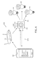
- FIG. 6 illustrates a mobile device and a third embodiment of alighting network.
- FIG. 7 illustrates another embodiment of a method of configuration of a physical control panel utilizing a mobile device user interface.
- Applicants have recognized and appreciated that it would be beneficial to provide various inventive methods and apparatus related to commissioning and configuration of a physical control device, such as alighting control panel, utilizing a mobile device.
- a physical control device such as alighting control panel
- various embodiments and implementations of the present invention are directed to configuration of a physical control panel.
- the approach may be implemented in other environmental control settings such as control of household appliances, control of audio or other media, control of blinds, and/or control of indoor climate related devices (heaters, air conditioners, fans, etc.).
- the lighting network includes a lighting controller 130 providing lighting control commands to a plurality of lighting fixtures 140 .
- a physical control panel 120 is in communication with the lighting controller 130 via a communication infrastructure 101 .
- the physical control panel 120 includes three buttons: an upper button 122 , a middle button 124 , and a lower button 126 . Although only a single physical control panel 120 is illustrated in FIG. 1 , one of ordinary skill in the art, having had the benefit of the present disclosure, will recognize and appreciate that additional physical control panels may be provided and may be in communication with lighting controller 130 or other controller of the lighting network.
- Such additional physical control panels may control one or more of lighting fixtures 140 and may have a similar configuration as physical control panel 120 and/or may have other configurations (e.g., containing on/off switches, dimmer slides, rotary dimmers, touch sensitive switches, different buttons, and/or a touch screen).
- Actuation of any one of the buttons 122 , 124 , and 126 generates an event that is transmitted over the communication infrastructure 101 to the lighting controller 130 .
- actuation of the upper button 122 generates a first event signal
- actuation of the middle button 124 generates a second event signal
- actuation of the lower button generates a third event signal.
- the events are received at the lighting controller 130 via communication infrastructure 101 and translated by the lighting controller 130 into one or more commands that are transmitted to the lighting fixtures 140 to effectuate a desired action.
- actuation of the upper button 122 may generate a first event signal that is translated by the lighting controller 130 into one or more commands that are transmitted to one or more of the lighting fixtures 140 to either turn certain task lighting on (if the task lighting was off) or turn certain task lighting off (if the task lighting was on).
- actuation of the middle button 124 may generate a second event signal that is translated by the lighting controller 130 into one or more commands that are transmitted to one or more of the lighting fixtures 140 to achieve a desired dimmed setting from those lighting fixtures 140 .
- actuation of the lower button 126 may generate a third event signal that is translated by the lighting controller 130 into one or more commands that are transmitted to one or more of the lighting fixtures 140 to turn one or more of the lighting fixtures 140 off.
- the lighting controller 130 is also in communication with a local configuration database 135 via communication infrastructure 101 .
- the local configuration database 135 contains data pertaining to one or more aspects of the present physical infrastructure of the lighting network.
- the configuration database may contain data pertaining to physical control panels (e.g., data related to a representation of the physical control panels, data related to the event generating capabilities of the physical control panels, data related to the actions currently associated with the events of the physical control panels), sensors (e.g., types, capabilities, locations), lighting controllers (e.g., types, capabilities, current settings), and/or lighting fixtures (e.g., types, capabilities, current settings, locations) that are attached to the lighting network.
- physical control panels e.g., data related to a representation of the physical control panels, data related to the event generating capabilities of the physical control panels, data related to the actions currently associated with the events of the physical control panels
- sensors e.g., types, capabilities, locations
- lighting controllers e.g., types, capabilities, current settings
- the local configuration database 135 may optionally be in communication with one or more supplier configuration databases 105 via communication infrastructure 101 and the internet 103 or other network to obtain data for one or more components of the lighting network.
- the supplier configuration databases 105 may retain certain data for one or more components of the lighting network without providing such data to the local configuration database 135 and may supplement or replace the local configuration database 135 .
- the lighting controller 130 and local configuration database 135 are illustrated as separate components in FIG. 1 , one of ordinary skill in the art, having had the benefit of the present disclosure, will recognize and appreciate that in some embodiments the lighting controller 130 and the local configuration database 135 may be a single component (e.g., a package including a controller and associated memory).
- the communication infrastructure 101 may include one or more wired and/or wireless communication mediums and one or more communications protocols.
- the communication mediums may include any physical medium, including, for example, twisted pair coaxial cables, fiber optics, or a wireless link using, for example, infrared, microwave, or encoded visible light transmissions and any suitable transmitters, receivers or transceivers to effectuate communication in the lighting fixture network.
- the communications protocols may include any suitable protocol for data transmission, including, for example, TCP/IP, variations of Ethernet, Universal Serial Bus, Bluetooth, FireWire, Zigbee, DMX, Dali, 802.11b, 802.11a, 802.11g, token ring, a token bus, serial bus, power line networking over mains or low voltage power lines, and/or any other suitable wireless or wired protocol.
- the physical control panel properties 128 may alternatively or additionally be transmitted via RF by the physical control panel 120 .
- the Bluetooth standard may be utilized to transmit the physical control panel properties 128 .
- the physical control panel properties 128 may alternatively or additionally be detected by reading or more barcodes affixed to or in close proximity the physical control panel 120 utilizing image processing capabilities of the mobile device 150 .
- barcodes For example, Quick Response (QR) barcodes, Semacode barcodes, High Capacity Color Barcodes, Shot Code barcodes, Aztec barcodes, matrix barcodes, and/or other barcodes (e.g., proprietary barcodes) having an optical machine-readable representation of data may be utilized.
- QR Quick Response
- Semacode barcodes Semacode barcodes
- High Capacity Color Barcodes Shot Code barcodes
- Aztec barcodes Aztec barcodes
- matrix barcodes e.g., and/or other barcodes (e.g., proprietary barcodes)
- the mobile device 150 obtains a representation of the physical control panel 152 from the configuration database 135 via mobile device communication link 159 and communication infrastructure 101 .
- the mobile device 150 may also obtain a listing of events that may be generated by the physical control panel 120 , a listing of any actions 154 that are currently associated with the events that may be generated by the physical control panel 120 , and/or a listing of other available actions 156 that may additionally or alternatively be associated with one or more of the events that may be generated by the physical control panel 120 .
- the configuration database 135 may optionally obtain the physical representation and/or one or more of the listings from the supplier configuration database 105 .
- the mobile device 150 may alternatively communicate directly with the supplier configuration database 105 via mobile device communication link 159 , communication infrastructure 101 , and the internet 103 to obtain the physical representation and/or one or more of the listings. In some embodiments the mobile device 150 may alternatively communicate directly with the physical control panel 120 to obtain the physical representation and/or one or more of the listings. In some embodiments the mobile device 150 may generate one or more of the other available actions 156 that may additionally or alternatively be associated with one or more of the events that may be generated by the physical control panel 120 .
- the associated actions 154 are provided near the representation of the physical control panel 152 and illustrate that the initial event generated by actuation of the upper button 122 accomplishes the action of turning certain task lighting on, the initial event generated by actuation of the middle button 124 accomplishes the action of generating a dimmed setting with certain lighting fixtures, and the initial event generated by actuation of the lower button 126 accomplishes the action of turning off certain lighting fixtures.
- the other available functions 156 on the mobile device 150 e.g., utilizing a touchscreen of the mobile device 150
- a screen such as that illustrated in FIG. 2 may be presented.
- FIG. 2 illustrates a screen of the mobile device 150 showing a representation of the physical control panel 152 , a listing of actions 154 A, 154 B, 154 C that are associated with events on the representation of the physical control panel 152 , and a listing of actions 156 A, 156 B that may be associated with events on the representation of the physical control panel 152 .
- Actions 154 A illustrate act ions that are performed in response to the event generated by actuation of the upper button 122 . Certain task lighting is turned on in response to an initial actuation of the upper button 122 and certain task lighting is turned off in response to the succeeding actuation of the upper button 122 .
- Actions 154 B illustrate actions that are performed in response to the event generated by actuation of the middle button 124 .
- a dimmed setting of certain lighting fixtures is generated in response to an initial actuation of the middle button 124 , a first scene setting is generated in response to the second actuation of the middle button 124 , and a second scene setting is generated in response to a third actuation of the middle button 124 .
- Action 154 C illustrates the action that is performed in response to the event generated by actuation of the lower button 126 . Certain lighting fixtures are turned off (if they are on) in response to actuation of the lower button 126 .
- Two additional available actions 156 A (Increase Light Level) and 156 B (Decrease Light Level) are also illustrated.
- a user may associate one or both of those available actions 156 A, 156 B to one or more events of the representation of the physical lighting control 152 utilizing the mobile device 150 .
- a user may replace both actions 154 A with available action 156 A so that when the upper button 122 is actuated, the lighting level is increased when possible.
- a user may additionally or alternatively replace all three actions 154 B with available action 156 B so that when the middle button 124 is actuated, the lighting level is decreased when possible.
- a user may click (e.g., a finger point on a touch screen) and drag an action 156 A, 156 B to a desired button on the representation of the physical control panel 152 to associate that action with the event generated by the button.
- An action associated with a desired button may optionally be the only action associated with that button. For example, with certain actions and/or buttons it may be desirable to only associate a single action to an event generated by that button (e.g., lights off, increase light level, and/or decrease light level).
- An action associated with a desired button may optionally be provided along with other actions associated with that button.
- multiple act ions may be associated with an event and which action is selected may be based on a particular schedule (e.g., during morning hours an event generated by a dimmer control may effectuate a color temperature adjustment action whereas during evening hours the same event generated by the dimmer control may effectuate a brightness adjustment action).
- buttons are illustrated in FIGS. 1 and 2 , one of ordinary skill in the art, having had the benefit of the present disclosure, will recognize and appreciate that other physical control panels having alternative and/or additional control structure may be provided.
- physical control panels having a dimmer may be provided.
- a mobile device may be utilized as discussed herein to define an appropriate action for one or more events generated by the dimmer (e.g., associate whether actuation of the dimmer dims the light while maintaining color temperature or dims the light while changing the color temperature).
- modify scene 158 may be selected by a user to add and/or configure one or more lighting scene actions that may be associated with one or more events of the representation of the physical lighting control 152 utilizing the mobile device 150 .
- modify scene 158 FIG. 1
- a user may create a new lighting scene action at mobile device 150 based on data obtained from configuration database 135 and/or generated at mobile device 150 .
- a user may download an existing lighting scene action from supplier configuration database 105 . The user may then associate any configured and/or added lighting scene actions with one or more events of the representation of the physical lighting control 152 utilizing the mobile device 150 .
- possible lighting actions may be supplied by configuration database 135 , supplied by configuration database 105 , and/or created on the mobile device 150 .
- actions may be created on the mobile device 150 utilizing light scene creation software.
- some control values may be defined (e.g., dimming value, color point, RGB value, a value for every DMX position that the set of lighting fixtures uses).
- Such defined values may vary in time or may be derived from other content (e.g., taking samples from a picture or video).
- the light scene creation software may be effect based and the desired effect on the environment specified and translated into values for implementation by the lighting controller 130 .
- a user may also utilize mobile device 150 to alter the association of actions 154 A, 154 B, 154 C that are currently associated with events on the representation of the physical control panel 152 .
- the order of actions 154 B may be rearranged by clicking on one of the actions 154 B and moving that action up or down in the hierarchy of actions 154 B.
- actions 154 A may be associated with the middle button 124 and the actions 154 B may be associated with the upper button 122 .
- the mobile device 150 After associations between actions and events of the physical control panel 120 are made at the mobile device 150 , the mobile device 150 transmits those associations to the lighting controller 130 via mobile device communication link 159 and communication infrastructure 101 . For example, the associations may be transmitted to the configuration database 135 and the lighting controller 130 may access such associations from the configuration database 135 .
- the event When an event is generated by the physical control panel 120 , the event is sent to the lighting controller 130 and translated by the lighting controller 130 into one or more commands that are transmitted to the lighting fixtures 140 to effectuate the action associated with the event by the mobile device 150 .
- FIG. 3 illustrates another embodiment of a mobile device 250 adjacent another embodiment of a physical control panel 220 .
- the physical control panel includes a switch having a switch on segment 222 and a switch off segment 224 .
- Actuation of the switch off segment 224 transmits a switch off event that is transmitted by a lighting controller into one or more commands to effectuate turning off one or more lighting fixtures.
- Each actuation of the switch on segment 222 toggles between a plurality of lighting scenes that are graphically displayed as scene one indicator 223 A, scene two indicator 223 B, and scene three indicator 223 C.
- each of the indicators 223 A-C includes a cut out that is illuminated a first color (e.g., by an LED behind the cutout) when not active and generates a second color (e.g., by a separate LED behind the cutout) when active.
- Actuation of the switch on segment 222 the first time will cause scene one indicator 223 A to be illuminated a certain color and a first scene event to be transmitted to alighting controller and a first lighting scene action to occur.
- Actuation of the switch on segment 222 the second time will cause scene two indicator 223 B to be illuminated a certain color and a second scene event to be transmitted to a lighting controller and a second lighting scene action to occur.
- the mobile device 250 is in proximity to the physical control panel 220 and detects physical control panel properties 228 of the physical control panel 220 .
- the physical control panel properties 228 uniquely identify the physical control panel 220 in the lighting network utilizing, for example, one or more of the methods and/or apparatus described herein. Based on determined physical control panel properties 228 , the mobile device 250 may obtain representations of portions of the physical control panel from a configuration database or elsewhere (e.g., directly from the physical control panel 220 ).
- the mobile device 250 might also show a representation of extra buttons 254 D and 254 E on the screen 256 .
- the extra button 254 D is a scene four indicator and the extra button 254 E is a scene five indicator.
- the extra buttons 254 D, 254 E can be associated with actions for the lighting controller in a similar way as the indicators 223 A-C on the physical control panel 220 . Actuation of the extra buttons 254 D, 254 E at the mobile device 250 will cause an event to be generated by the mobile device 250 that is transmitted to the lighting controller to cause the associated lighting scene actions to occur.
- buttons 254 D, 254 E are shown immediately and by default when the mobile device 250 is held in the proximity of the physical control panel 220 .
- An indication that extra buttons are available on a mobile device may optionally be given at the control panel 220 .
- a user may utilize mobile device 250 to customize the actions that are associated with each of lighting scenes one through three that are accessible via the control panel 220 and with each of lighting scenes four and five that are accessible via the mobile device 250 .
- a user may also create additional lighting scenes and associate such additional scenes with existing or additional events utilizing additional available lighting scenes selection 256 .
- the mobile device 250 After scene indicators and their associated events are associated with an action at mobile device 250 , the mobile device 250 transmits those associations to one or more lighting controller via a mobile device communication link.
- the event When an event is generated by the physical control panel 220 , the event is sent to the lighting controller and translated by the lighting controller into one or more commands that are transmitted to one or more lighting fixtures to effectuate the action associated with the event.
- actions may be supplied by a database and/or created on the mobile device and associated with a supplied listing of events of the physical control panel.
- the associated actions and events may be transmitted to a controller.
- an action is effectuated via the controller in response to an associated event from the physical control panel.
- the physical control panel properties may contain information that links to a supplier's website and/or provides an address for a supplier configuration database 305 that corresponds to that physical control panel 320 A Utilizing the address, the mobile device 350 may locate and access the supplier configuration database 305 via the internet 303 to obtain additional data pertaining to physical control panel 320 A (e.g., data related to a representation of the physical control panel, data related to the event generating capabilities of the physical control panel).
- the mobile device 350 Based on determined physical control panel properties, the mobile device 350 obtains a representation of the physical control panel 352 from the supplier configuration database 305 via the internet 303 .
- the mobile device 350 also obtains a listing of events that may be generated by the physical control panel 320 A, and optionally a listing of any actions 354 that are currently associated with the events and/or a listing of other available actions 356 that may additionally or alternatively be associated with one or more of the events that may be generated by the physical control panel 320 A.
- one or more of the representation and/or listings may be provided to the mobile device 350 from physical control panel 320 A via mobile device communications link 359 .
- the mobile device 350 may have direct access to data related to the configuration of the lighting network and settings for the lighting network can be created on the mobile device 350 .
- the associated actions 354 are provided by the representation of the physical control panel 352 and illustrate that the initial event generated by actuation of the upper button 322 A accomplishes the action of turning certain task lighting on, the initial event generated by actuation of the middle button 324 A accomplishes the action of generating a dimmed setting with certain lighting fixtures, and the initial event generated by actuation of the lower button 326 A accomplishes the action of turning off certain lighting fixtures.
- a user may change the association between the buttons 324 A-C and the actions 354 and/or may modify and/or add action associations to the buttons 324 A-C via selection of the other available functions 356 and/or modify scene 358 (e.g., in a similar manner as discussed in conjunction with FIGS. 1 and 2 ).
- the mobile device 350 After associations between actions and events of the physical control panel 320 A are made at the mobile device 350 , the mobile device 350 transmits those associations to a local lighting controller of the physical control panel 320 A.
- a local lighting controller of the physical control panel 320 A When an event is generated by the physical control panel 320 A, commands are directly communicated by the physical control panel 320 A to one or more of the lighting fixtures 340 via the communication infrastructure 301 to effectuate the action associated with the event.
- the communication infrastructure 301 may utilize the DMX communications protocol.
- the physical control panel 320 B may be configured utilizing the mobile device 350 in a similar manner as described with respect to the physical control panel 320 A.
- one or more embodiments of the mobile devices may also provide an augmented user interface after association with the physical control panels.
- extended user interface elements relevant to the environment of the physical control panel may be offered on the mobile device.
- Such an augmented user interface on the mobile device may enable a user to, inter alia: set/adjust light and/or other parameters (e.g., audio selection, temperature) for the environment/room associated with the physical control panel; access additional lighting scenes which are not available through the physical control panel; and/or download lighting presets from the controller or from another mobile device.
- a mobile device may communicate with one or more controllers to effectuate such extended user interface elements.
- FIG. 6 illustrates a mobile device 450 and a third embodiment of alighting network.
- the lighting network includes a physical control panel 420 that includes a local lighting controller providing lighting control commands to a plurality of lighting fixtures 440 via a communication infrastructure 401 .
- the communication infrastructure 401 may include one or more wired and/or wireless communication mediums and one or more communications protocols.
- the communication infrastructure 401 may include wireless ZigBee communications.
- the physical control panel 420 is similar to physical control panel 220 of FIG. 3 and includes a switch on segment 422 and a switch off segment 424 . Actuation of the switch off segment 424 generates a switch off event that causes the lighting controller of the physical control panel 420 to effectuate turning off one or more lighting fixtures.
- Each actuation of the switch on segment 422 toggles between a plurality of lighting scenes that are graphically displayed as scene one indicator 423 A, scene two indicator 423 B, and scene three indicator 423 C.
- Actuation of the switch on segment 422 the first time will cause scene one indicator 423 A to be illuminated, a first scene event to be generated, and the lighting controller of the physical control panel 420 to cause a first lighting scene action to occur.
- Actuation of the switch on segment 422 the second time will cause scene two indicator 423 B to be illuminated, a second scene event to be transmitted to a lighting controller, and the lighting controller of the physical control panel 420 to cause a second lighting scene action to occur.
- Actuation of the switch on segment 422 the third time will cause scene three indicator 423 C to be illuminated, a third scene event to be generated, and the lighting controller of the physical control panel 420 to cause a third lighting scene action to occur.
- the transmitted scene events may be subsequent transmissions of the same signal or may each be unique signals.
- the physical control panel 420 may communicate with the mobile device 450 via direct communications link 429 A and/or via indirect communications link 429 B.
- the direct communications link 429 A may include, for example, Bluetooth, RFID, and/or NFC.
- the indirect communications link 429 B may include, for example, a standard wireless communication protocol transmitted over a network implemented via router 421 .
- Additional physical control panels may also be in communication with the mobile device 450 .
- additional physical control panels may be in communication with the mobile device 450 via router 421 .
- the physical control panels may make themselves discoverable to the mobile device 450 via router 421 , may communicate physical control panel properties to the mobile device 450 , may communicate properties of attached light sources to the mobile device 450 , and may control attached light sources to create one or more light source actions such as lighting scene actions.
- a software application is installed on the mobile device 450 that enables viewing of all physical control panels that are in communication with the mobile device 450 .
- the software application enables a user to choose a desired physical control panel from the plurality of physical control panels and view information concerning its connected light sources.
- the software application also enables a user to program a lighting scene for the selected one of the physical control panels.
- the mobile device 450 may detect physical control panel properties of the physical control panel 420 via router 421 that uniquely identify the physical control panel.
- the physical control panel properties may include one or more of supplier information, device type identification, and/or address information within the lighting network.
- the mobile device 450 Based on determined physical control panel properties, the mobile device 450 obtains a listing of events that may be generated by the physical control panel 420 , and optionally a listing of any actions that are currently associated with the events and/or a listing of other available actions that may additionally or alternatively be associated with one or more of the events that may be generated by the physical control panel 420 .
- the mobile device 450 may optionally also obtain a representation of the physical control panel 420 from a supplier configuration database or elsewhere (e.g., from the physical control panel 420 directly). After associations between lighting actions and events of the physical control panel 420 are made at the mobile device 450 , the mobile device 450 transmits those associations to the lighting controller of the physical control panel 420 .
- commands are directly communicated by the controller of the physical control panel 420 to one or more of the light sources 440 via the communication infrastructure 401 to effectuate the action associated with the event.
- FIG. 7 illustrates an embodiment of a method of configuration of the physical control panel 420 utilizing the mobile device 450 .
- a user associates the physical control panel 420 with the light sources 440 .
- the association between the physical control panel 420 and the light sources 440 may be accomplished utilizing a commissioning method.
- the commissioning method may be based on an existing commissioning method called “TouchLink”, that utilizes communications between a remote control and ZigBee enabled light sources.
- a user associates the physical control panel 420 with a communications network such as the indirect communications link 429 B provided by router 421 .
- the physical control panel 420 may be associated with a communications network utilizing one or more WiFi commissioning techniques.
- Wi-Fi Protected Setup WPS
- a Push-Button-Method may be utilized in which the user simply has to push a button (either an actual button or virtual button) on both the router 421 and the physical control panel 420 .
- a Near-Held-Communication Method may be utilized in which the user simply has to bring the physical control panel 420 and the router 421 in close proximity to allow a near field communication between the devices.
- a user places the mobile device 450 within a detection range of the communications link 429 B provided by router 421 to enable the mobile device 450 to detect all physical control panels that are in the network.
- the networked physical control panels are always discoverable by the mobile device 450 (e.g., by broadcasting a discovery message via router 421 at a regular interval).
- a software application on the mobile device 450 detects the physical control panels in the network (e.g., via detection of the discovery messages transmitted by the physical control panels) and provides a representation of the detected physical control panels to the user. For example, in FIG. 6 the mobile device 450 is displaying the discovered physical control panels “Living Room,” “Kitchen,” “Dining Room,” and “Garden.”
- a user selects one of the detected physical control panels 420 on the mobile device 450 .
- the mobile device 450 sends a selection message to the selected physical control panel 420 .
- the selected physical control panel 420 communicates all connected light sources 440 , the available light parameters of all connected light sources 440 , and current light parameter values to the mobile device 450 .
- the mobile device 450 may graphically display the connected light sources 440 of the physical control panel 420 along with the light parameters of those light sources 440 and/or the current light parameter values.
- alighting scene action is selected on the mobile device 450 for one or more of the light sources 440 connected to the physical control panel 420 .
- a user selects one of the light sources from the connected light sources 440 of the physical control panel 420 on the mobile device 450 .
- the mobile device 450 provides an interface for the selected light source based on the light parameters of the light source and enables the user to alter the values of the light parameters.
- the mobile device 450 may send the new action values to the selected light source via the controller of the physical control panel 420 .
- changes to the selected light source on the mobile device 450 are immediately communicated to the light source and made immediately visible to the user.
- a user may repeat step 478 for different light sources connected to the physical control panel 420 if desired to create a particular lighting scene action.
- lighting scene actions may be alternatively selected on the mobile device 450 utilizing other methods than individual user adjustment of light sources.
- image based scene creation may be utilized wherein an image on the mobile device 450 is translated to light parameters of the light sources.
- one or more lighting scene databases may be consulted to create one or more lighting scene actions.
- the user associates, on the mobile device 450 , an event of the selected physical control panel with the selected lighting scene action.
- a physical representation of the selected physical control panel 420 may be provided on the mobile device 450 and pressing a pertinent portion of the physical representation of the selected physical control panel 420 on the mobile device 450 longer than a predefined threshold may associate a recently selected lighting scene action with a related event.
- a physical representation of scene one indicator 423 A may be pressed by a user on the mobile device 450 for three seconds or longer to associate a recently selected lighting scene action with the scene one event generated by the switch on segment 422 .
- the mobile device 450 transmits the associated lighting scene actions and events to a controller of the physical control panel 420 .
- the mobile device 450 sends a program request to the controller of the selected physical control panel to store the selected lighting scene action as related to the correct event of the physical control panel 420 .
- the controller of the physical control panel 420 may optionally send a program request to one or more of the light sources 440 to associate their current value with the pertinent event of the selected physical control panel 420 .
- the light sources may be directed to associate their current value with the event of the selected physical control panel that is associated with the selected lighting scene action.
- the lighting scene action is effectuated via the controller in response to an associated event at the physical control panel 420 .
- an event is generated by the physical control panel 420
- commands are directly communicated by the physical control panel 420 to one or more of the associated light sources 440 via the communication infrastructure 401 to effectuate the action associated with the event.
- inventive embodiments are presented by way of example only and that, within the scope of the appended claims and equivalents thereto, inventive embodiments may be practiced otherwise than as specifically described and claimed.
- inventive embodiments of the present disclosure are directed to each individual feature, system, article, material, kit, and/or method described herein.
- the phrase “at least one,” in reference to a list of one or more elements, should be understood to mean at least one element selected from any one or more of the elements in the list of elements, but not necessarily including at least one of each and every element specifically listed within the list of elements and not excluding any combinations of elements in the list of elements.
- This definition also allows that elements may optionally be present other than the elements specifically identified within the list of elements to which the phrase “at least one” refers, whether related or unrelated to those elements specifically identified.
Landscapes
- Engineering & Computer Science (AREA)
- Computer Networks & Wireless Communication (AREA)
- Signal Processing (AREA)
- Automation & Control Theory (AREA)
- Physics & Mathematics (AREA)
- Electromagnetism (AREA)
- General Physics & Mathematics (AREA)
- Circuit Arrangement For Electric Light Sources In General (AREA)
Priority Applications (1)
| Application Number | Priority Date | Filing Date | Title |
|---|---|---|---|
| US14/383,680 US9820359B2 (en) | 2012-03-08 | 2013-03-04 | Methods and apparatus for configuration of control devices |
Applications Claiming Priority (3)
| Application Number | Priority Date | Filing Date | Title |
|---|---|---|---|
| US201261608286P | 2012-03-08 | 2012-03-08 | |
| US14/383,680 US9820359B2 (en) | 2012-03-08 | 2013-03-04 | Methods and apparatus for configuration of control devices |
| PCT/IB2013/051712 WO2013132416A1 (en) | 2012-03-08 | 2013-03-04 | Methods and apparatus for configuration of control devices |
Publications (2)
| Publication Number | Publication Date |
|---|---|
| US20150015165A1 US20150015165A1 (en) | 2015-01-15 |
| US9820359B2 true US9820359B2 (en) | 2017-11-14 |
Family
ID=48182962
Family Applications (1)
| Application Number | Title | Priority Date | Filing Date |
|---|---|---|---|
| US14/383,680 Active 2033-04-18 US9820359B2 (en) | 2012-03-08 | 2013-03-04 | Methods and apparatus for configuration of control devices |
Country Status (6)
| Country | Link |
|---|---|
| US (1) | US9820359B2 (enExample) |
| EP (1) | EP2823692B1 (enExample) |
| JP (1) | JP6214572B2 (enExample) |
| CN (1) | CN104160787B (enExample) |
| RU (1) | RU2638156C2 (enExample) |
| WO (1) | WO2013132416A1 (enExample) |
Cited By (1)
| Publication number | Priority date | Publication date | Assignee | Title |
|---|---|---|---|---|
| US20210240149A1 (en) * | 2014-08-22 | 2021-08-05 | Lutron Technology Company Llc | Load control system responsive to location of an occupant and mobile devices |
Families Citing this family (46)
| Publication number | Priority date | Publication date | Assignee | Title |
|---|---|---|---|---|
| US9906838B2 (en) | 2010-07-12 | 2018-02-27 | Time Warner Cable Enterprises Llc | Apparatus and methods for content delivery and message exchange across multiple content delivery networks |
| WO2014040118A1 (en) * | 2012-09-06 | 2014-03-20 | Lifi Labs Inc | Controllable lighting devices |
| TWI508627B (zh) * | 2013-03-22 | 2015-11-11 | Internat Mobile Iot Corp | 照明控制系統 |
| US10047912B2 (en) | 2013-10-15 | 2018-08-14 | LIFI Labs, Inc. | Lighting assembly |
| JP2015088341A (ja) * | 2013-10-30 | 2015-05-07 | パナソニックIpマネジメント株式会社 | 調光卓 |
| US11455884B2 (en) | 2014-09-02 | 2022-09-27 | LIFI Labs, Inc. | Lighting system |
| CN105900531B (zh) | 2013-11-14 | 2019-03-29 | 莱弗实验室公司 | 可复位的照明系统及方法 |
| US9198262B1 (en) | 2014-05-22 | 2015-11-24 | LIFI Labs, Inc. | Directional lighting system and method |
| US20150160935A1 (en) * | 2013-12-06 | 2015-06-11 | Vivint, Inc. | Managing device configuration information |
| EP2890223B1 (en) * | 2013-12-27 | 2020-05-27 | Panasonic Intellectual Property Corporation of America | Method for controlling mobile terminal and program for controlling mobile terminal |
| DE102014200297B4 (de) | 2014-01-10 | 2025-03-27 | Tridonic Gmbh & Co Kg | Betriebsgerät und Kommunikationsadapter für den Außeneinsatz |
| CN106165545B (zh) * | 2014-02-28 | 2019-07-26 | 飞利浦灯具控股公司 | 用于配置触摸控制照明器的方法和相关的照明器 |
| EP3123836A1 (en) | 2014-03-28 | 2017-02-01 | Robert Bosch GmbH | Configuring lighting electronics using database and mobile device |
| US20150283703A1 (en) * | 2014-04-03 | 2015-10-08 | Brain Corporation | Apparatus and methods for remotely controlling robotic devices |
| US10032364B2 (en) * | 2014-05-15 | 2018-07-24 | Savant Systems, Llc | Standalone wireless lighting application |
| WO2015179786A1 (en) | 2014-05-22 | 2015-11-26 | LIFI Labs, Inc. | Directional lighting system and method |
| US9629227B2 (en) * | 2014-07-11 | 2017-04-18 | Ideal Industries, Inc. | Systems and methods for pre-commissioning a wireless lighting control system |
| WO2016019005A1 (en) * | 2014-07-29 | 2016-02-04 | Lumifi, Inc. | Automated and pre-configured set up of light scenes |
| US9648448B2 (en) | 2014-09-02 | 2017-05-09 | LIFI Labs, Inc. | Power outlet and method of use |
| WO2016078918A1 (en) * | 2014-11-18 | 2016-05-26 | Philips Lighting Holding B.V. | Apparatus and method for hidden activation of a commissioning mode |
| US20180332690A1 (en) * | 2014-11-18 | 2018-11-15 | Philips Lighting Holding B.V. | Apparatus and method for resetting a non-powered electronic device |
| WO2016083066A1 (en) * | 2014-11-24 | 2016-06-02 | Philips Lighting Holding B.V. | Controlling lighting dynamics |
| JP6601709B2 (ja) * | 2015-03-11 | 2019-11-06 | パナソニックIpマネジメント株式会社 | 照明制御装置及び照明制御方法 |
| EP3096304B1 (en) * | 2015-05-18 | 2020-05-06 | Helvar Oy Ab | Method and arrangement for controlling appliances from a distance |
| EP3320757B1 (en) * | 2015-07-10 | 2020-09-16 | Signify Holding B.V. | Controller for a lighting arrangement |
| CN105404167A (zh) * | 2015-09-30 | 2016-03-16 | 北京清川科技有限公司 | 一种云平台、基于二维码的智能家电控制系统及方法 |
| ITUB20154945A1 (it) * | 2015-10-29 | 2017-04-29 | Freedompro Srl | Sistema domotico multiprotocollo configurabile da utente. |
| JP6418710B2 (ja) * | 2015-12-11 | 2018-11-07 | 株式会社遠藤照明 | 照明システム、設定装置、照明制御方法、及び、照明制御プログラム |
| DE102016104347B4 (de) * | 2016-03-10 | 2020-07-30 | Insta Gmbh | Vereinfachtes Inbetriebnahmekonzept zum Ansteuern von Aktoren einer Gebäudeinstallation |
| US10057966B2 (en) * | 2016-04-05 | 2018-08-21 | Ilumisys, Inc. | Connected lighting system |
| DE102016207919A1 (de) * | 2016-05-09 | 2017-11-09 | Tridonic Gmbh & Co Kg | Mobiles Kommunikationsgerät mit einer Benutzerschnittstellendarstellung abhängig von einem an einer Schnittstelle erfassten Parameter |
| US9967959B2 (en) * | 2016-07-07 | 2018-05-08 | Noon Home, Inc. | Intelligent lighting control system learning exclusion apparatuses, systems, and methods |
| US10440794B2 (en) | 2016-11-02 | 2019-10-08 | LIFI Labs, Inc. | Lighting system and method |
| US11038708B2 (en) * | 2017-03-02 | 2021-06-15 | Signify Holding B.V. | Control events in a system of networked home devices |
| MX385009B (es) | 2017-03-15 | 2025-03-14 | Lutron Tech Co Llc | Configuracion de un sistema de control de carga |
| US10813197B2 (en) * | 2017-04-10 | 2020-10-20 | Ideal Industries Lighting Llc | Wireless solid state lighting controller |
| DE102018129678A1 (de) * | 2018-11-26 | 2020-05-28 | Insta Gmbh | Verfahren zum Einrichten eines Ansteuergerätes in einem Gebäudeinstallationsnetzwerk |
| CN110312355A (zh) * | 2019-07-19 | 2019-10-08 | 安徽亿联网络科技有限公司 | 一种智能场景切换系统 |
| WO2021136711A1 (en) | 2020-01-02 | 2021-07-08 | Signify Holding B.V. | Displaying a light control ui on a device upon detecting interaction with a light control device |
| JP7756720B2 (ja) * | 2021-01-15 | 2025-10-20 | シグニファイ ホールディング ビー ヴィ | 照明システムを構成するためのコントローラ及びその方法 |
| EP4075923A1 (en) * | 2021-04-13 | 2022-10-19 | Helvar Oy Ab | Method, arrangement, and computer program product for wireless control of lighting |
| WO2022226363A2 (en) * | 2021-04-22 | 2022-10-27 | Lutron Technology Company Llc | Configuration and control of load control systems |
| EP4595705A1 (en) | 2022-09-30 | 2025-08-06 | Signify Holding B.V. | Device and method for lighting control |
| CN117850252A (zh) * | 2022-09-30 | 2024-04-09 | 华为终端有限公司 | 智能设备控制方法、电子设备及系统 |
| FR3147674B1 (fr) * | 2023-04-04 | 2025-11-07 | Somfy Activites Sa | Procédé de configuration d’une installation domotique. |
| US20250016901A1 (en) * | 2023-07-05 | 2025-01-09 | Ledup Manufacturing Group Limited | Integrated power controller for led system |
Citations (29)
| Publication number | Priority date | Publication date | Assignee | Title |
|---|---|---|---|---|
| US20010017615A1 (en) | 1999-12-10 | 2001-08-30 | Chih-Shu Lin | Intelligent touch-type universal remote control |
| WO2005043484A1 (en) | 2003-11-04 | 2005-05-12 | Koninklijke Philips Electronics N.V. | Universal remote control device with touch screen |
| JP2005158560A (ja) | 2003-11-27 | 2005-06-16 | Seiko Epson Corp | 電気器具制御システム |
| WO2006100650A2 (en) | 2005-03-23 | 2006-09-28 | Koninklijke Philips Electronics, N.V. | Light condition recorder system and method |
| CN1949949A (zh) | 2006-08-23 | 2007-04-18 | 中国科学院计算技术研究所 | 一种led灯光无线控制系统 |
| JP2007287682A (ja) | 2006-03-23 | 2007-11-01 | Mitsubishi Electric Corp | 機器管理装置、機器設定器、照明制御システムおよび制御システム |
| WO2008029323A1 (en) | 2006-09-06 | 2008-03-13 | Philips Intellectual Property & Standards Gmbh | Lighting control |
| US20080168267A1 (en) | 2007-01-09 | 2008-07-10 | Bolen Charles S | System and method for dynamically configuring a mobile device |
| US20080183316A1 (en) * | 2007-01-26 | 2008-07-31 | Autani Corporation | Upgradeable Automation Devices, Systems, Architectures, and Methods |
| WO2008142644A1 (en) | 2007-05-24 | 2008-11-27 | Koninklijke Philips Electronics N.V. | System and method for automatically creating a specific atmosphere by controlling contributions of sensorial perceptible stimulus means |
| WO2008146245A1 (en) | 2007-06-01 | 2008-12-04 | Koninklijke Philips Electronics N. V. | A user interface and a method for the easy creation of atmospheres with an atmosphere creation system |
| US7550935B2 (en) | 2000-04-24 | 2009-06-23 | Philips Solid-State Lighting Solutions, Inc | Methods and apparatus for downloading lighting programs |
| US20090239587A1 (en) * | 2008-03-19 | 2009-09-24 | Universal Electronics Inc. | System and method for appliance control via a personal communication or entertainment device |
| US20100052939A1 (en) * | 2008-09-01 | 2010-03-04 | Po-Hsiang Liang | Lighting System and Related Method Capable of Reducing Electricity Consumption |
| WO2010067246A1 (en) | 2008-12-08 | 2010-06-17 | Koninklijke Philips Electronics N. V. | A system and method for copying settings of a device to another device, particularly for copying settings between lamps |
| WO2010143089A1 (en) | 2009-06-09 | 2010-12-16 | Koninklijke Philips Electronics, N.V. | Systems and apparatus for automatically deriving and modifying personal preferences applicable to multiple controllable lighting networks |
| US20110169413A1 (en) * | 2008-09-26 | 2011-07-14 | Koninklijke Philips Electronics N.V. | System and method for controlling a lighting system with a plurality of light sources |
| WO2011161643A1 (en) | 2010-06-25 | 2011-12-29 | Koninklijke Philips Electronics N.V. | Controlling the access to a user interface for atmosphere control with an atmosphere creation system |
| US20130030589A1 (en) * | 2011-06-30 | 2013-01-31 | Lutron Electronics Co., Inc. | Load Control Device Having Internet Connectivity |
| US20140070919A1 (en) * | 2012-09-05 | 2014-03-13 | Crestron Electronics, Inc. | User Identification and Location Determination in Control Applications |
| US20140252983A1 (en) * | 2013-03-11 | 2014-09-11 | Gunitech Corp. | Method for Controlling Lamps and Computer Program Product Thereof |
| US8872442B2 (en) * | 2011-12-06 | 2014-10-28 | Panasonic Corporation | Illumination system |
| US8878451B2 (en) * | 2011-05-25 | 2014-11-04 | Lg Electronics Inc. | Lighting system and method for controlling the same |
| US8909056B2 (en) * | 2008-03-02 | 2014-12-09 | Lumenetix, Inc. | Lighting node systems and methods |
| US20150195883A1 (en) * | 2014-01-06 | 2015-07-09 | Cree, Inc. | Power over ethernet lighting fixture |
| US20150264784A1 (en) * | 2014-03-17 | 2015-09-17 | Shafrir Romano | Wireless ready lighting driver |
| EP2945469A1 (en) * | 2014-05-13 | 2015-11-18 | Yu-Sheng So | Illuminance configuring illumination system and method using the same |
| US20160021723A1 (en) * | 2011-12-07 | 2016-01-21 | Abl Ip Holding Llc | System for and Method of Commissioning Lighting Devices |
| US9386666B2 (en) * | 2011-06-30 | 2016-07-05 | Lutron Electronics Co., Inc. | Method of optically transmitting digital information from a smart phone to a control device |
Family Cites Families (6)
| Publication number | Priority date | Publication date | Assignee | Title |
|---|---|---|---|---|
| US20020014972A1 (en) * | 1998-02-20 | 2002-02-07 | Michael T. Danielson | Control station for control system with automatic detection and configuration of control elements |
| FR2798861B1 (fr) * | 1999-09-09 | 2001-12-21 | Anghel Muscocea | Appareil de musculation pour faire des pompes |
| JP4658566B2 (ja) * | 2004-10-29 | 2011-03-23 | シャープ株式会社 | 遠隔操作装置および遠隔制御システム |
| JP2010213045A (ja) * | 2009-03-11 | 2010-09-24 | Toshiba Lighting & Technology Corp | 負荷機器制御システム |
| WO2011013035A1 (en) * | 2009-07-29 | 2011-02-03 | Koninklijke Philips Electronics N.V. | Managing atmosphere programs for atmosphere creation systems |
| CN201893971U (zh) * | 2010-11-12 | 2011-07-06 | 北京朗波尔光电股份有限公司 | 基于gprs与dmx512的led景观灯控制系统 |
-
2013
- 2013-03-04 RU RU2014140546A patent/RU2638156C2/ru active
- 2013-03-04 JP JP2014560487A patent/JP6214572B2/ja active Active
- 2013-03-04 EP EP13718392.7A patent/EP2823692B1/en active Active
- 2013-03-04 CN CN201380012971.1A patent/CN104160787B/zh active Active
- 2013-03-04 US US14/383,680 patent/US9820359B2/en active Active
- 2013-03-04 WO PCT/IB2013/051712 patent/WO2013132416A1/en not_active Ceased
Patent Citations (29)
| Publication number | Priority date | Publication date | Assignee | Title |
|---|---|---|---|---|
| US20010017615A1 (en) | 1999-12-10 | 2001-08-30 | Chih-Shu Lin | Intelligent touch-type universal remote control |
| US7550935B2 (en) | 2000-04-24 | 2009-06-23 | Philips Solid-State Lighting Solutions, Inc | Methods and apparatus for downloading lighting programs |
| WO2005043484A1 (en) | 2003-11-04 | 2005-05-12 | Koninklijke Philips Electronics N.V. | Universal remote control device with touch screen |
| JP2005158560A (ja) | 2003-11-27 | 2005-06-16 | Seiko Epson Corp | 電気器具制御システム |
| WO2006100650A2 (en) | 2005-03-23 | 2006-09-28 | Koninklijke Philips Electronics, N.V. | Light condition recorder system and method |
| JP2007287682A (ja) | 2006-03-23 | 2007-11-01 | Mitsubishi Electric Corp | 機器管理装置、機器設定器、照明制御システムおよび制御システム |
| CN1949949A (zh) | 2006-08-23 | 2007-04-18 | 中国科学院计算技术研究所 | 一种led灯光无线控制系统 |
| WO2008029323A1 (en) | 2006-09-06 | 2008-03-13 | Philips Intellectual Property & Standards Gmbh | Lighting control |
| US20080168267A1 (en) | 2007-01-09 | 2008-07-10 | Bolen Charles S | System and method for dynamically configuring a mobile device |
| US20080183316A1 (en) * | 2007-01-26 | 2008-07-31 | Autani Corporation | Upgradeable Automation Devices, Systems, Architectures, and Methods |
| WO2008142644A1 (en) | 2007-05-24 | 2008-11-27 | Koninklijke Philips Electronics N.V. | System and method for automatically creating a specific atmosphere by controlling contributions of sensorial perceptible stimulus means |
| WO2008146245A1 (en) | 2007-06-01 | 2008-12-04 | Koninklijke Philips Electronics N. V. | A user interface and a method for the easy creation of atmospheres with an atmosphere creation system |
| US8909056B2 (en) * | 2008-03-02 | 2014-12-09 | Lumenetix, Inc. | Lighting node systems and methods |
| US20090239587A1 (en) * | 2008-03-19 | 2009-09-24 | Universal Electronics Inc. | System and method for appliance control via a personal communication or entertainment device |
| US20100052939A1 (en) * | 2008-09-01 | 2010-03-04 | Po-Hsiang Liang | Lighting System and Related Method Capable of Reducing Electricity Consumption |
| US20110169413A1 (en) * | 2008-09-26 | 2011-07-14 | Koninklijke Philips Electronics N.V. | System and method for controlling a lighting system with a plurality of light sources |
| WO2010067246A1 (en) | 2008-12-08 | 2010-06-17 | Koninklijke Philips Electronics N. V. | A system and method for copying settings of a device to another device, particularly for copying settings between lamps |
| WO2010143089A1 (en) | 2009-06-09 | 2010-12-16 | Koninklijke Philips Electronics, N.V. | Systems and apparatus for automatically deriving and modifying personal preferences applicable to multiple controllable lighting networks |
| WO2011161643A1 (en) | 2010-06-25 | 2011-12-29 | Koninklijke Philips Electronics N.V. | Controlling the access to a user interface for atmosphere control with an atmosphere creation system |
| US8878451B2 (en) * | 2011-05-25 | 2014-11-04 | Lg Electronics Inc. | Lighting system and method for controlling the same |
| US20130030589A1 (en) * | 2011-06-30 | 2013-01-31 | Lutron Electronics Co., Inc. | Load Control Device Having Internet Connectivity |
| US9386666B2 (en) * | 2011-06-30 | 2016-07-05 | Lutron Electronics Co., Inc. | Method of optically transmitting digital information from a smart phone to a control device |
| US8872442B2 (en) * | 2011-12-06 | 2014-10-28 | Panasonic Corporation | Illumination system |
| US20160021723A1 (en) * | 2011-12-07 | 2016-01-21 | Abl Ip Holding Llc | System for and Method of Commissioning Lighting Devices |
| US20140070919A1 (en) * | 2012-09-05 | 2014-03-13 | Crestron Electronics, Inc. | User Identification and Location Determination in Control Applications |
| US20140252983A1 (en) * | 2013-03-11 | 2014-09-11 | Gunitech Corp. | Method for Controlling Lamps and Computer Program Product Thereof |
| US20150195883A1 (en) * | 2014-01-06 | 2015-07-09 | Cree, Inc. | Power over ethernet lighting fixture |
| US20150264784A1 (en) * | 2014-03-17 | 2015-09-17 | Shafrir Romano | Wireless ready lighting driver |
| EP2945469A1 (en) * | 2014-05-13 | 2015-11-18 | Yu-Sheng So | Illuminance configuring illumination system and method using the same |
Cited By (1)
| Publication number | Priority date | Publication date | Assignee | Title |
|---|---|---|---|---|
| US20210240149A1 (en) * | 2014-08-22 | 2021-08-05 | Lutron Technology Company Llc | Load control system responsive to location of an occupant and mobile devices |
Also Published As
| Publication number | Publication date |
|---|---|
| JP2015513188A (ja) | 2015-04-30 |
| RU2014140546A (ru) | 2016-04-27 |
| EP2823692A1 (en) | 2015-01-14 |
| JP6214572B2 (ja) | 2017-10-18 |
| CN104160787A (zh) | 2014-11-19 |
| US20150015165A1 (en) | 2015-01-15 |
| CN104160787B (zh) | 2017-08-01 |
| EP2823692B1 (en) | 2018-05-16 |
| WO2013132416A1 (en) | 2013-09-12 |
| RU2638156C2 (ru) | 2017-12-12 |
Similar Documents
| Publication | Publication Date | Title |
|---|---|---|
| US9820359B2 (en) | Methods and apparatus for configuration of control devices | |
| EP3092876B1 (en) | Method for sharing and/or synchronizing attributes of emitted light among lighting systems | |
| US11582058B2 (en) | Identifying and controlling signal influence on one or more properties of emitted light | |
| JP6290463B2 (ja) | レガシ照明制御コンポーネント用プロキシ | |
| RU2731365C2 (ru) | Способ и система для управления осветительным устройством | |
| CN107926099B (zh) | 用于配置照明系统中的设备的方法 | |
| EP3424277A1 (en) | Lighting scene selection based on operation of one or more individual light sources | |
| WO2020007762A1 (en) | A controller for configuring a lighting system | |
| US11665802B2 (en) | Lighting system | |
| JP6541893B2 (ja) | 1つ以上の個々の光源の操作に基づく照明シーン選択 |
Legal Events
| Date | Code | Title | Description |
|---|---|---|---|
| AS | Assignment |
Owner name: KONINKLIJKE PHILIPS ELECTRONICS N V, NETHERLANDS Free format text: ASSIGNMENT OF ASSIGNORS INTEREST;ASSIGNORS:CUPPEN, ROEL PETER GEERT;ENGELEN, DIRK VALENTINUS RENE;CLOUT, RAMON ANTOINE WIRO;AND OTHERS;SIGNING DATES FROM 20140210 TO 20140707;REEL/FRAME:033689/0109 |
|
| AS | Assignment |
Owner name: PHILIPS LIGHTING HOLDING B.V., NETHERLANDS Free format text: ASSIGNMENT OF ASSIGNORS INTEREST;ASSIGNOR:KONINKLIJKE PHILIPS N.V.;REEL/FRAME:040060/0009 Effective date: 20160607 |
|
| STCF | Information on status: patent grant |
Free format text: PATENTED CASE |
|
| AS | Assignment |
Owner name: SIGNIFY HOLDING B.V., NETHERLANDS Free format text: CHANGE OF NAME;ASSIGNOR:PHILIPS LIGHTING HOLDING B.V.;REEL/FRAME:050837/0576 Effective date: 20190201 |
|
| MAFP | Maintenance fee payment |
Free format text: PAYMENT OF MAINTENANCE FEE, 4TH YEAR, LARGE ENTITY (ORIGINAL EVENT CODE: M1551); ENTITY STATUS OF PATENT OWNER: LARGE ENTITY Year of fee payment: 4 |
|
| MAFP | Maintenance fee payment |
Free format text: PAYMENT OF MAINTENANCE FEE, 8TH YEAR, LARGE ENTITY (ORIGINAL EVENT CODE: M1552); ENTITY STATUS OF PATENT OWNER: LARGE ENTITY Year of fee payment: 8 |