US9804390B2 - Virtual image observation optical system and light guide prism - Google Patents
Virtual image observation optical system and light guide prism Download PDFInfo
- Publication number
- US9804390B2 US9804390B2 US14/642,916 US201514642916A US9804390B2 US 9804390 B2 US9804390 B2 US 9804390B2 US 201514642916 A US201514642916 A US 201514642916A US 9804390 B2 US9804390 B2 US 9804390B2
- Authority
- US
- United States
- Prior art keywords
- blocking portion
- light blocking
- light
- light guide
- guide prism
- Prior art date
- Legal status (The legal status is an assumption and is not a legal conclusion. Google has not performed a legal analysis and makes no representation as to the accuracy of the status listed.)
- Active, expires
Links
Images


Classifications
-
- G—PHYSICS
- G02—OPTICS
- G02B—OPTICAL ELEMENTS, SYSTEMS OR APPARATUS
- G02B27/00—Optical systems or apparatus not provided for by any of the groups G02B1/00 - G02B26/00, G02B30/00
- G02B27/01—Head-up displays
- G02B27/0101—Head-up displays characterised by optical features
-
- G—PHYSICS
- G02—OPTICS
- G02B—OPTICAL ELEMENTS, SYSTEMS OR APPARATUS
- G02B27/00—Optical systems or apparatus not provided for by any of the groups G02B1/00 - G02B26/00, G02B30/00
- G02B27/0018—Optical systems or apparatus not provided for by any of the groups G02B1/00 - G02B26/00, G02B30/00 with means for preventing ghost images
-
- G—PHYSICS
- G02—OPTICS
- G02B—OPTICAL ELEMENTS, SYSTEMS OR APPARATUS
- G02B27/00—Optical systems or apparatus not provided for by any of the groups G02B1/00 - G02B26/00, G02B30/00
- G02B27/01—Head-up displays
- G02B27/0149—Head-up displays characterised by mechanical features
-
- G—PHYSICS
- G02—OPTICS
- G02B—OPTICAL ELEMENTS, SYSTEMS OR APPARATUS
- G02B27/00—Optical systems or apparatus not provided for by any of the groups G02B1/00 - G02B26/00, G02B30/00
- G02B27/01—Head-up displays
- G02B27/017—Head mounted
- G02B27/0172—Head mounted characterised by optical features
-
- G—PHYSICS
- G02—OPTICS
- G02B—OPTICAL ELEMENTS, SYSTEMS OR APPARATUS
- G02B27/00—Optical systems or apparatus not provided for by any of the groups G02B1/00 - G02B26/00, G02B30/00
- G02B27/01—Head-up displays
- G02B27/0149—Head-up displays characterised by mechanical features
- G02B2027/0161—Head-up displays characterised by mechanical features characterised by the relative positioning of the constitutive elements
-
- G—PHYSICS
- G02—OPTICS
- G02B—OPTICAL ELEMENTS, SYSTEMS OR APPARATUS
- G02B5/00—Optical elements other than lenses
- G02B5/04—Prisms
Definitions
- the present invention relates to a virtual image observation optical system for guiding image light from a display element to an observer's eyeball and displaying a virtual image of the display element within the observer's field of view, and a light guide prism used in the virtual image observation optical system.
- Such a display device employs a virtual image observation optical system using a light guide prism for guiding the image of the display element.
- V-shaped groove a groove having a V-shaped cross section
- ghost light a method of forming successive V-shaped grooves in the side surface of the prism to remove the light
- the method of forming successive V-shaped grooves in the side surface of the light guide prism has a problem in that, since the surface of the light guide prism has no flat part, the light guide prism cannot be brought into contact with and securely fixed to a flat part of a housing. Besides, forming V-shaped grooves in the entire side surface causes a problem in that a gate, an eject pin, and the like necessary for resin molding cannot be placed. It is also a problem that, when a gate portion by resin molding is located on the side surface of the light guide prism, the gate portion is visible to the observer. The gate for resin molding remains as a rough surface after molding. If light striking this part is visible, noise light such as flare light appears and degrades the performance of the optical system.
- An invention of a virtual image observation optical system is a virtual image observation optical system for observing a virtual image of an image displayed by a display element, the virtual image observation optical system including: the display element; at least one light guide prism that guides image light from the display element; and an eyepiece that causes the guided image light to enter an observer's eyeball, wherein the at least one light guide prism has a first light blocking portion and a second light blocking portion in at least one side surface of side surfaces that surround a light path for guiding the image light from an incident surface to an exit surface of the light guide prism, and the first light blocking portion and the second light blocking portion are arranged so that a shaded area and an invisible area overlap each other at least partly and cover an intermediate area between the first light blocking portion and the second light blocking portion on the at least one side surface, where the shaded area is an area shadowed from the image light due to the first light blocking portion, and the invisible area is an area invisible during virtual image observation by the observer due to the second light blocking portion.
- the incident surface of the at least one light guide prism faces a display surface of the display element;
- D is a width of an effective display area of an image of the display element formed by an optical element between the display element and the first light blocking portion, in a direction perpendicular to the side surface in which the first light blocking portion and the second light blocking portion are formed;
- P is a width of the light guide prism between the side surface in which the first light blocking portion and the second light blocking portion are formed and a side surface facing the side surface, in a cross section perpendicular to the optical axis;
- W v is a distance between the first light blocking portion and
- the incident surface of the at least one light guide prism faces a display surface of the display element;
- D is a width of an effective display area of an image of the display element formed by an optical element between the display element and the first light blocking portion, in a direction perpendicular to the side surface in which the first light blocking portion and the second light blocking portion are formed;
- P is a width of the light guide prism between the side surface in which the first light blocking portion and the second light blocking portion are formed and a side surface facing the side surface, in a cross section perpendicular to the optical axis;
- W v is a distance between the first light blocking portion and the image of
- the intermediate area is formed as a flat surface.
- a gate for resin injection may be placed in the intermediate area for molding the light guide prism. It is also preferable to form an attachment portion for fixing to a housing or a protrusion portion for positioning, in the intermediate area.
- first light blocking portion and the second light blocking portion may be a groove.
- the first light blocking portion may be a notch or a light blocking portion provided at an outer edge of the incident surface of the light guide prism.
- An invention of a light guide prism is a light guide prism used in a virtual image observation optical system for guiding image light from a display element to an observer's eyeball and displaying a virtual image of the display element within the observer's field of view
- the light guide prism including: an incident surface and an exit surface for the image light; a plurality of side surfaces that surround a light path of the image light; and a first light blocking portion and a second light blocking portion formed in at least one side surface of the plurality of side surfaces, wherein the first light blocking portion and the second light blocking portion are arranged so that a shaded area and an invisible area overlap each other at least partly and cover an intermediate area between the first light blocking portion and the second light blocking portion on the at least one side surface, where the shaded area is an area shadowed from the image light due to the first light blocking portion, and the invisible area is an area invisible during virtual image observation by the observer due to the second light blocking portion.
- FIG. 1 is a perspective view of a display device using a virtual image observation optical system according to Embodiment 1;
- FIG. 2 is a schematic diagram showing the virtual image observation optical system according to Embodiment 1;
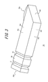
- FIG. 3 is a perspective view of a light guide prism in FIG. 1 ;
- FIG. 4A is a sectional view showing the optical system in FIG. 2 linearly developed along its optical axis;
- FIG. 4B is a side view showing the optical system in FIG. 2 linearly developed along its optical axis as seen from the direction perpendicular to the section in FIG. 4A
- FIG. 5 is a diagram for describing a range of a width s of a shaded area A s in FIG. 4B ;
- FIG. 6 is a diagram for describing a range of a width h of an invisible area A i in FIG. 4B ;
- FIG. 7 is a diagram showing arrangement of a projection position by a gate and an eject pin in injection molding of the light guide prism
- FIG. 8 is a sectional view of the light guide prism having a positioning protrusion
- FIG. 9A is a diagram for describing blocking of ghost light by absorption by a first V-shaped groove
- FIG. 9B is an enlarged view of the first V-shaped groove portion in FIG. 9A ;
- FIG. 10A is a diagram for describing blocking of ghost light by total reflection by the first V-shaped groove
- FIG. 10B is an enlarged view of the first V-shaped groove portion in FIG. 10A ;
- FIG. 11 is a schematic diagram showing a display element-side part of a virtual image observation optical system according to Embodiment 2;
- FIG. 12 is a schematic diagram showing a virtual image observation optical system according to Embodiment 3 linearly developed along its optical axis.
- FIG. 13 is a schematic diagram showing a virtual image observation optical system according to Embodiment 4 linearly developed along its optical axis.
- FIG. 1 is a perspective view showing an example of a display device using a virtual image observation optical system according to Embodiment 1.
- a display device 1 includes: a support portion 2 (temples of glasses) shaped like glasses for fixedly supporting the whole display device 1 on an observer's head; a body portion 3 fixed to the support portion 2 and including a display element 20 (see FIG. 2 ); and a light guide prism 30 one end of which is supported by the body portion 3 and the other end of which extends to be in front of the observer's eye in a state where the display device 1 is worn by the observer.
- the body portion 3 includes, in addition to the display element 20 , an electronic circuit for displaying an image on the display element 20 , a communication function for receiving image data wiredly or wirelessly from outside the body portion 3 , and the like.
- FIG. 2 is a schematic diagram showing a virtual image observation optical system 10 according to Embodiment 1.
- FIG. 3 is a perspective view of the light guide prism 30 .
- the virtual image observation optical system 10 includes the display element 20 and the light guide prism 30 .
- the display element 20 is a liquid crystal display element, an organic EL element, or the like having a rectangular display surface 20 a for displaying an image to be observed, and is included in the body portion 3 .
- the light guide prism 30 is a prism made of transparent resin and long in one direction, and has one end held in a housing of the body portion 3 .
- the light guide prism 30 has an incident surface 30 a and a reflection surface 30 b at both ends in the longitudinal direction which is the image light optical axis direction.
- the incident surface 30 a faces the display surface of the display element 20 , inside the body portion 3 .
- the reflection surface 30 b is formed as a surface the internal surface of which is inclined at about 45° toward the observer when wearing the display device, with respect to the optical axis direction of the light guide prism 30 .
- the reflection surface 30 b preferably has no coating to satisfy the condition of total reflection for image light traveling in the light guide prism 30 in the optical axis direction, but may be formed as a mirror surface coated by aluminum sputtering or the like according to need.
- the light guide prism 30 also has, between the incident surface 30 a and the reflection surface 30 b , a first side surface 30 c , a second side surface 30 d , a third side surface 30 e , and a fourth side surface 30 f so as to surround the path of image light.
- the first side surface 30 c faces the observer's face
- the second side surface 30 d is the upper surface of the light guide prism 30
- the third side surface 30 e is opposite to the surface facing the observer's face
- the fourth side surface 30 f is the lower surface of the light guide prism 30 .
- the first side surface 30 c and the third side surface 30 e face each other
- the second side surface 30 d and the fourth side surface 30 f face each other.
- the light guide prism 30 also has an exit surface 30 g from which the image light reflected off the reflection surface 30 b exits toward the observer's eyeball 7 , at the end of the first side surface 30 c opposite to the display element 20 .
- the exit surface 30 g is formed as a lens surface having positive refractive power, to display a virtual image of the display image of the display element 20 in the observer's sight.
- the exit surface 30 g of the light guide prism 30 constitutes an eyepiece.
- the exit surface 30 g need not necessarily be on the same plane as the first side surface 30 c , and may be inclined from the first side surface 30 c to direct the optical axis toward the observer's eyeball 7 .
- the optical axis O of the virtual image observation optical system 10 matches the optical axis of the lens of the exit surface 30 g , and passes through the substantial center of the rectangular display surface 20 a of the display element 20 and the incident surface 30 a , bends at the substantial center of the reflection surface 30 b , and passes through the exit surface 30 g.
- a first V-shaped groove 31 (first light blocking portion) and a second V-shaped groove 32 (second light blocking portion) are formed apart from each other in the direction of the optical axis O in a part of the light guide prism 30 covered with the housing of the body portion 3 , so as to surround the side surfaces 30 c to 30 f .
- the first V-shaped groove 31 and the second V-shaped groove 32 are intended to prevent part of image light emitted from the display element 20 from reflecting off any side surface of the light guide prism 30 and entering the observer's eyeball 7 to thereby cause a ghost.
- the grooves shaped like the letter V in the side surfaces of the light guide prism 30 near such positions where unwanted reflection occurs, ghost light caused by unwanted reflection can be blocked with the grooves functioning as a flare stop.
- FIGS. 4A and 4B are diagrams showing the optical system in FIG. 2 linearly developed along the optical axis, where FIG. 4A is a sectional view and FIG. 4B is a side view as seen from the direction perpendicular to the section in FIG. 4A .
- FIGS. 4A and 4B show the optical system as a linear optical system by omitting the reflection by the reflection surface 30 b , for the purpose of illustration.
- R 1 is the most inclined ray of light emitted from the display surface 20 a of the display element 20 and passing through the vertex of the first V-shaped groove 31 .
- the part between the ray of light R 1 and the first V-shaped groove 31 on the first side surface 30 c is a shaded area A s shadowed from the image light from the display element 20 .
- R 2 is the most inclined line of sight traced backward from the eyepiece and passing through the vertex of the second V-shaped groove 32 .
- the part between the line of sight R 2 and the second V-shaped groove 32 on the first side surface 30 c is an invisible area A i not visible from the exit surface 30 g (eyepiece) (i.e. not visible from the observer).
- Part of the shaded area A s is a visible area, but is substantially invisible because it is not exposed to light from the display element 20 .
- the part between the first groove 31 and the second groove 32 on the first side surface 30 c is covered with the shaded area A s and the invisible area A i , and the shaded area A s and the invisible area A i overlap each other in the hatched part in FIG. 4B .
- an inter-groove area A m intermediate area
- the shaded area A s and the invisible area A i partly overlap each other, a wide flat surface part that is substantially invisible can be secured.
- FIG. 5 is a diagram for describing the width s of the shaded area A s in FIG. 4B .
- the light guide prism 30 is situated at a distance W from the display element 20 .
- the display position of the virtual display element 21 is at a distance nW from the incident surface 30 a of the light guide prism 30 , where the light path length is equal when the air layer is converted into the same medium as the light guide prism 30 .
- n is the refractive index of the light guide prism 30
- R 1 ′ is the path of a virtual ray of light emitted from the virtual display element 21 .
- FIG. 6 is a diagram for describing the width h of the invisible area A i in FIG. 4B .
- the width Q of the exit surface 30 g in the direction perpendicular to the first side surface 30 c be less than the width P of the light guide prism 30 in the same direction.
- c be the height of the second V-shaped groove 32 from the first side surface 30 c
- L 2 be the distance from the vertex of the second V-shaped groove 32 to the exit surface 30 g in the optical axis direction
- h be the width (the width of the invisible area A i ) from the vertex of the second V-shaped groove 32 to the incident surface 30 a -side end of the invisible area A i .
- the light guide prism 30 is configured to satisfy the following expression: s ⁇ M ⁇ s+h (5) where M is the width between the vertex of the first V-shaped groove 31 and the vertex of the second V-shaped groove 32 in the direction of the optical axis O.
- M is the width between the vertex of the first V-shaped groove 31 and the vertex of the second V-shaped groove 32 in the direction of the optical axis O.
- a typical arrangement method is to arrange the V-shaped grooves at such intervals that make the shaded areas A s of the respective V-shaped grooves overlap each other.
- the left inequality in Expression (5) i.e.
- the greater width M of the inter-groove area A m than the width s of the shaded area A s means that the wider inter-groove area A m can be secured exceeding the width s of the shaded area A s formed by the display element 20 and the first V-shaped groove 31 .
- the right inequality means that the shaded area A s and the invisible area A i overlap each other at least partly in the inter-groove area A m , so that the inter-groove area A m between the first V-shaped groove 31 and the second V-shaped groove 32 on the first side surface 30 c is completely covered with the shaded area A s and the invisible area A i .
- the light guide prism 30 has the continuous flat inter-groove area A m that is relatively wide. This area can be used as a flat surface for fixing the light guide prism 30 in the body portion 3 .
- the inter-groove area A m of the light guide prism 30 does not contribute to the light guide of a normal imaging luminous flux for forming a virtual image, and light resulting in ghost light either is blocked by the first V-shaped groove 31 and does not enter the inter-groove area A m or, even if reflected in this area, is invisible from the exit surface 30 g due to the second V-shaped groove 32 .
- the inter-groove area A m does not need to be a surface excellent in optical property. In other words, even when the surface has low flatness or the material around this surface is of uneven quality, the performance of the virtual image observation optical system 10 is affected little.
- the inter-groove area A m can therefore be put to various uses as described below.
- FIG. 7 is a diagram showing arrangement of a projection position by a gate 37 and an eject pin 38 in injection molding of the light guide prism 30 .
- molten resin is injected from the gate 37 into a mold having a cavity in the shape of the light guide prism 30 .
- the gate 37 is cut off when removed from the mold after injection molding. The cut surface is rougher than the other surfaces, and also the injected material tends to be of uneven quality near the gate 37 .
- the eject pin 38 is used to remove the molded light guide prism 30 from the mold.
- a depression or a contour mark of the eject pin 38 tends to remain due to pressure applied through the eject pin 38 .
- a protrusion that is mated to the housing of the body portion 3 may be provided in the inter-groove area A m , to accurately position the light guide prism 30 in the body portion 3 .
- FIG. 8 is a simplified sectional view of the light guide prism 30 having a positioning protrusion 39 .
- the positioning protrusion 39 may be placed only on the first side surface 30 c , or a plurality of positioning protrusions 39 may be placed in the inter-groove area A m of the first side surface 30 c to the fourth side surface 30 f .
- Various other arrangements are also possible.
- the gate 37 for injection molding may be placed above the positioning protrusion 39 in FIG. 8 .
- the wide, flat inter-groove area A m can be secured on the side surface of the light guide prism 30 , so that the light guide prism 30 can be fixed by holding the inter-groove area A m .
- the inter-groove area A m does not affect the optical performance of the light guide prism 30 , and therefore can be used for manufacturing or holding of the light guide prism 30 .
- FIG. 9A is a diagram for describing blocking of ghost light by absorption by the first V-shaped groove 31
- FIG. 9B is an enlarged view of the first V-shaped groove 31 portion.
- the inclined surface of the first V-shaped groove 31 blocks light by a light blocking paint.
- the incident surface 30 a of the light guide prism 30 in this modification is a surface having positive refractive power.
- the virtual display element 21 is larger than the actual display element 20 .
- a ray of light R 3 emitted from the display element 20 is incident on the inclined surface of the first V-shaped groove 31 and is absorbed here.
- FIG. 10A is a diagram for describing blocking of ghost light by total reflection by the first V-shaped groove 31
- FIG. 10B is an enlarged view of the first V-shaped groove 31 portion.
- the incident surface 30 a of the light guide prism 30 is a surface having positive refractive power.
- a ray of light R 3 emitted from the display element 20 is totally reflected off the incident surface 30 a -side inclined surface of the first V-shaped groove 31 formed in the first side surface 30 c .
- the condition of total reflection here can be defined by the following expression using an incidence angle ⁇ shown in FIG. 10B :
- the reflected ray of light R 3 is incident on the third side surface 30 e facing the first side surface 30 c at a small incidence angle, and exits to the outside of the light guide prism 30 .
- the first V-shaped groove 31 need not be coated with the light blocking paint. This simplifies the manufacturing process, and also eliminates the possibility that the optical performance degrades due to peeling or the like of the light blocking paint.
- FIG. 11 is a schematic diagram showing a display element 20 -side part of the virtual image observation optical system 11 according to Embodiment 2.
- Surfaces 40 a to 40 g of the light guide prism 40 in this embodiment respectively correspond to the surfaces 30 a to 30 g of the light guide prism 30 in Embodiment 1.
- the corner between the incident surface 40 a and each of the first side surface 40 c to the fourth side surface 40 f is notched and subjected to light blocking treatment to form a notch 41 (first light blocking portion), instead of the first V-shaped groove 31 in Embodiment 1.
- a V-shaped groove 42 (second light blocking portion) corresponding to the second V-shaped groove 32 in Embodiment 1 is formed in the first side surface 40 c to the fourth side surface 40 f , so as to surround the light guide prism 40 .
- the other structure is the same as that in Embodiment 1.
- W be the distance from the display surface of the display element 20 to the incident surface 40 a of the light guide prism 40
- n the refractive index of the light guide prism 40
- s be the width from the incident surface 40 a to the exit surface 40 g -side end of the shaded area A s not exposed to image light due to the notch 41
- D be the width of the effective display area of the virtual display element 21 in the direction perpendicular to the first side surface 40 c
- P be the width of the light guide prism 40 between the first side surface 40 c and the third side surface 40 e in the cross section perpendicular to the optical axis O
- a be the height of the notch 41 from the first side surface 40 c .
- the width Q of the exit surface 40 g in the direction perpendicular to the first side surface 40 c be less than the width P of the light guide prism 40 in the direction perpendicular to the first side surface 40 c .
- c be the height of the V-shaped groove 42 from the first side surface 40 c
- L 2 be the distance from the vertex of the V-shaped groove 42 to the exit surface 40 g in the light guide prism 40 in the optical axis direction
- h be the width (the width of the invisible area A i ) from the vertex of the V-shaped groove 42 to the incident surface 40 a -side end of the invisible area A i .
- the same Expressions (3) and (4) as in Embodiment 1 then hold true for the invisible area A i .
- M be the width of the area A m (intermediate area) between the notch 41 and the vertex of the V-shaped groove 42 in the direction of the optical axis O.
- the width M is set to satisfy Expression (5) as in Embodiment 1.
- the outer peripheral edges of the flat incident surface 40 a of the light guide prism 40 may be coated with a light blocking film, or the outer peripheral edges of the incident surface 40 a may be covered with a light blocking member.
- the part shielded from light by the light blocking film or the light blocking member has the height a from the first side surface 30 c.
- the wide, flat inter-groove area A m not affecting the optical performance of the light guide prism 40 can be secured on the side surface of the light guide prism 40 as in Embodiment 1, thus achieving the same advantageous effects as in Embodiment 1.
- the provision of the notch 41 instead of the first V-shaped groove eases the molding and the light blocking treatment, as compared with Embodiment 1.
- FIG. 12 is a schematic diagram showing a virtual image observation optical system 12 according to Embodiment 3 linearly developed along the optical axis O.
- the virtual image observation optical system 12 differs from those in Embodiments 1 and 2 in that it includes two light guide prisms, namely, a first light guide prism 50 and a second light guide prism 55 , in addition to the display element 20 .
- the following describes the structure of the virtual image observation optical system 12 with reference to the drawing.
- the first light guide prism 50 is a hexahedral prism having an incident surface 50 a , an exit surface 50 g , and a first side surface 50 c to a fourth side surface 50 f arranged between the incident surface 50 a and the exit surface 50 g so as to surround the path of image light.
- the first light guide prism 50 does not have a reflection surface for bending the light path like the reflection surface 30 b of the light guide prism 30 in Embodiment 1, and the incident surface 50 a and the exit surface 50 g face each other.
- the incident surface 50 a is a lens surface having positive refractive power
- the exit surface 50 g is a flat surface.
- a first V-shaped groove 51 (first light blocking portion) and a second V-shaped groove 52 (second light blocking portion) are formed in the first side surface 50 c to the fourth guide surface 50 f of the first light guide prism 50 , so as to surround the side surfaces of the light guide prism 50 .
- the second light guide prism 55 is a hexahedral prism having an incident surface 55 a , a reflection surface (not shown) for bending the path of image light by about 90°, and a first side surface 55 c to a fourth side surface 55 f arranged between the incident surface 55 a and the reflection surface so as to surround the path of image light (only the first side surface 55 c and the third side surface 55 e are shown in FIG. 12 ).
- the first side surface 55 c is provided with an exit surface 55 g from which the image light exits toward the eyeball 7 .
- the exit surface 55 g is a lens surface having positive refractive power.
- the exit surface 55 g is an eyepiece in this embodiment.
- the display element 20 , the first light guide prism 50 , and the second light guide prism 55 are arranged with the exit surface 50 g of the first light guide prism 50 and the incident surface 55 a of the second light guide prism 55 facing each other at a predetermined interval apart.
- the first light guide prism 50 and the second light guide prism 55 are arranged so that, in the developed virtual image observation optical system 12 in FIG.
- the incident surface 50 a of the first light guide prism 50 having positive refractive power and the exit surface 55 g of the second light guide prism 55 have the matching optical axis O and this optical axis O passes through the substantial center of the display element 20 , the incident surface 50 a and exit surface 50 g of the first light guide prism 50 , and the incident surface 55 a and exit surface 55 g of the second light guide prism 55 .
- the display element 20 , the first light guide prism 50 , and the second light guide prism 55 are each held to the body portion 3 by a holding mechanism not shown, and are positioned relative to each other. Light is blocked between the exit surface 50 g of the first light guide prism 50 and the incident surface 55 a of the second light guide prism 55 so as to prevent incidence of outside light.
- a ray of light R 1 in FIG. 12 is the most inclined ray of light emitted from the display element 20 and passing through the vertex of the first V-shaped groove 51 (first light blocking portion), as in Embodiment 1.
- the incident surface 50 a has refractive power, and so the ray of light R 1 is bent at the incident surface 50 a .
- the virtual display element 21 represents the image of the display element 20 (the virtual image of the display element) formed by the optical element (i.e. the light guide prism 50 and its incident surface 50 a ) from the display element 20 to the first V-shaped groove 51 , at the position as converted into the distance in the light guide prism.
- a straight line is drawn as a virtual ray of light R 1 ′ from the outer edge of the effective area of the virtual display element 21 through the vertex of the first V-shaped groove 51 .
- the part between the first V-shaped groove 51 and the point of intersection of the ray of light R 1 ′ with the first side surface 50 c is the shaded area A s not exposed to image light from the display element 20 .
- the width s of the shaded area A s can be calculated by Expression (2), using the distance W v between the first V-shaped groove 51 and the display element image 21 as converted into the distance in the light guide prism.
- R 2 is the most inclined line of sight traced backward from the pupil 7 a of the eyeball 7 and passing through the vertex of the second V-shaped groove 52 (second light blocking portion).
- the part between the point of intersection of the line of sight R 2 with the first side surface 50 c and the second V-shaped groove 52 is the invisible area A i not visible from the exit surface 55 g (eyepiece).
- the difference from Embodiment 1 lies in that the starting point from which the line of sight R 2 for determining the invisible area A i is traced backward is not the exit surface 55 g of the second light guide prism 55 but the observer's pupil 7 a .
- the inclination of the line of sight R 2 is more gentle, which increases the width of the invisible area A i as compared with the case where the line of sight R 2 is drawn with the outermost edge of the exit surface 55 g as the starting point.
- a virtual eyeball 8 of the user represents the image (virtual image) of the eyeball 7 formed by the optical element (i.e. the second light guide prism 55 and the exit surface 50 g side of the second V-shaped groove 52 of the first light guide prism 50 ) from the eyeball 7 to the second V-shaped groove 52 , at the position as converted into the distance in the light guide prisms 50 and 55 .
- the optical element i.e. the second light guide prism 55 and the exit surface 50 g side of the second V-shaped groove 52 of the first light guide prism 50
- a virtual line of sight R 2 ′ from the outer edge of the pupil 8 a of the virtual eyeball 8 through the vertex of the second V-shaped groove 52 is drawn.
- the part between the second V-shaped groove 52 and the point of intersection of the line of sight R 2 ′ with the first side surface 50 c is the invisible area A i .
- the width of the inter-groove area A m between the first V-shaped groove 51 and the second V-shaped groove 52 in the direction of the optical axis O can be set wide in the range where the shaded area A s and the invisible area A i overlap each other at least partly.
- the shaded area A s and the invisible area A i formed on the first side surface 50 c of the first light guide prism 50 in this embodiment partly overlap each other as in Embodiment 1. Accordingly, the wide inter-groove area A m not affecting the optical performance of the first light guide prism 50 can be secured, thus achieving the same advantageous effects as in Embodiment 1.
- the invisible area A i is designed not based on the outer edge of the exit surface 55 g of the light guide prism but based on the line of sight R 2 passing through the observer's pupil 7 a , as compared with the light guide prism in Embodiment 1. This further widens the invisible area A i , enabling the wider inter-groove area A m to be secured.
- FIG. 13 is a schematic diagram showing a virtual image observation optical system 13 according to Embodiment 4 linearly developed along the optical axis O.
- the virtual image observation optical system 13 includes a first light guide prism 60 and a second light guide prism 65 .
- a first V-shaped groove 66 (first light blocking portion) and a second V-shaped groove 67 (second light blocking portion) are formed in the second light guide prism 65 , in addition to the first light guide prism 60 .
- Each component in the first light guide prism 60 and the second light guide prism 65 is given a reference numeral obtained by adding 10 to the reference numeral of the corresponding component in Embodiment 3.
- side surfaces 65 c of the second light guide prism 65 have the shaded area A s shadowed from the image light from the display element 20 due to the first V-shaped groove 66 and the invisible area A i invisible during virtual image observation by the observer due to the second V-shaped groove 67 .
- the shaded area A s and the invisible area A i overlap each other at least partly, and cover the inter-groove area A m between the first V-shaped groove 66 and the second V-shaped groove 67 on the first side surface 65 c.
- the wide inter-groove area A m not affecting the optical performance of the light guide prism can be secured not only on the first light guide prism 60 but also on the second light guide prism 65 .
- the second light guide prism 65 can be fixed by holding the inter-groove area A m , too.
- the inter-groove area A m does not affect the optical performance of the light guide prism 65 , and so can be used as the arrangement position of a gate and an eject pin during manufacture and used for holding or positioning.
- the present invention is not limited to the foregoing embodiments, and various modifications and changes are possible.
- the display device is shaped like glasses, the display device to which the virtual image observation optical system and the light guide prism according to the present invention are applicable is not limited to this.
- the display device may have any of various shapes such as goggles and a helmet, so long as it can be fixed to the user's head.
- the light guide prism is not limited to a structure that is horizontally long during use.
- a vertically long light guide prism may be used with the display element being located in front of the head.
- each of the foregoing embodiments describes a virtual image observation optical system and a light guide prism for the right eye, the present invention is equally applicable to the left eye.
- first light blocking portion and the second light blocking portion are arranged along each surface of the light guide prism so as to surround the light guide prism
- the arrangement of the first light blocking portion and the second light blocking portion is not limited to this.
- the first light blocking portion and the second light blocking portion may be formed in two facing side surfaces of the light guide prism.
- the first light blocking portion and the second light blocking portion may be formed in one side surface or three side surfaces.
- the virtual image observation optical system is not limited to the structure of including one or two light guide prisms, and may include three or more light guide prisms.
- Embodiment 2 describes the structure in which a notch or a light blocking portion is formed in the incident surface of the light guide prism, a notch or a light blocking portion may be formed in the exit surface of the light guide prism as a second light blocking portion.
- the width of the eyepiece is less than the width of the light guide prism, the width of the eyepiece may be equal to the width of the light guide prism.
Landscapes
- Physics & Mathematics (AREA)
- General Physics & Mathematics (AREA)
- Optics & Photonics (AREA)
- Optical Elements Other Than Lenses (AREA)
Applications Claiming Priority (2)
| Application Number | Priority Date | Filing Date | Title |
|---|---|---|---|
| JP2014-047849 | 2014-03-11 | ||
| JP2014047849A JP6218649B2 (ja) | 2014-03-11 | 2014-03-11 | 虚像観察光学系および導光プリズム |
Publications (2)
| Publication Number | Publication Date |
|---|---|
| US20150260988A1 US20150260988A1 (en) | 2015-09-17 |
| US9804390B2 true US9804390B2 (en) | 2017-10-31 |
Family
ID=54068669
Family Applications (1)
| Application Number | Title | Priority Date | Filing Date |
|---|---|---|---|
| US14/642,916 Active 2035-08-18 US9804390B2 (en) | 2014-03-11 | 2015-03-10 | Virtual image observation optical system and light guide prism |
Country Status (2)
| Country | Link |
|---|---|
| US (1) | US9804390B2 (ja) |
| JP (1) | JP6218649B2 (ja) |
Cited By (1)
| Publication number | Priority date | Publication date | Assignee | Title |
|---|---|---|---|---|
| US11785323B1 (en) * | 2022-05-27 | 2023-10-10 | Samsung Electronics Co., Ltd. | Camera module including refractive member and electronic device including refractive member |
Families Citing this family (14)
| Publication number | Priority date | Publication date | Assignee | Title |
|---|---|---|---|---|
| JP6777358B2 (ja) * | 2015-12-09 | 2020-10-28 | コピン コーポレーション | 装着型映像表示装置 |
| JP6697253B2 (ja) * | 2015-12-17 | 2020-05-20 | コピン コーポレーション | 装着型映像表示装置及び接眼光学系 |
| US9851478B2 (en) * | 2016-02-10 | 2017-12-26 | Microsoft Technology Licensing, Llc | Optical cross talk mitigation for optical device having disrupting features formed on a shield |
| US10049501B1 (en) * | 2016-10-14 | 2018-08-14 | Oculus Vr, Llc | Crosstalk mitigation for virtual reality |
| JP2018101521A (ja) | 2016-12-20 | 2018-06-28 | オムロン株式会社 | 導光板、面光源装置、表示装置及び電子機器 |
| JP6368387B2 (ja) * | 2017-01-25 | 2018-08-01 | 株式会社三共 | 遊技機 |
| US11009707B2 (en) | 2017-06-06 | 2021-05-18 | Apple Inc. | Optical systems for electronic devices with displays |
| US10911656B2 (en) | 2017-11-21 | 2021-02-02 | Microsoft Technology Licensing, Llc | Optical isolation systems for displays |
| FI128594B (en) * | 2017-12-22 | 2020-08-31 | Dispelix Oy | Stair waveguide elements, personal display device and method for producing an image |
| US11181735B2 (en) | 2018-02-15 | 2021-11-23 | Tdg Acquisition Company, Llc | Optic and assembly for reduced reflections |
| KR102664395B1 (ko) * | 2018-10-18 | 2024-05-08 | 삼성전자주식회사 | 투시형 디스플레이 장치 |
| US11402642B2 (en) | 2019-11-03 | 2022-08-02 | Facebook Technologies, Llc | Head-mounted display assemblies and related methods for interpupillary distance adjustments |
| TWI768696B (zh) * | 2020-12-23 | 2022-06-21 | 大立光電股份有限公司 | 用於相機模組的光轉折元件、相機模組與電子裝置 |
| TWI769815B (zh) * | 2021-02-03 | 2022-07-01 | 大立光電股份有限公司 | 塑膠光轉折元件、成像鏡頭模組及電子裝置 |
Citations (7)
| Publication number | Priority date | Publication date | Assignee | Title |
|---|---|---|---|---|
| JPH02248918A (ja) * | 1989-03-23 | 1990-10-04 | Matsushita Electric Ind Co Ltd | 3色色分解光学ユニット |
| JPH09269405A (ja) | 1996-03-29 | 1997-10-14 | Fuji Photo Optical Co Ltd | プリズム |
| US20060017834A1 (en) * | 2004-07-23 | 2006-01-26 | Konica Minolta Opto, Inc. | Imaging optical system and imaging lens device |
| JP2007183444A (ja) | 2006-01-10 | 2007-07-19 | Sony Corp | 光学素子の反射防止用塗料及び光学素子 |
| US20100321781A1 (en) * | 2006-12-28 | 2010-12-23 | Nokia Corporation | Device for expanding an exit pupil in two dimensions |
| JP4766913B2 (ja) | 2004-05-17 | 2011-09-07 | オリンパス株式会社 | 頭部装着型画像表示装置 |
| US20130083404A1 (en) * | 2011-09-30 | 2013-04-04 | Seiko Epson Corporation | Virtual image display device |
Family Cites Families (5)
| Publication number | Priority date | Publication date | Assignee | Title |
|---|---|---|---|---|
| JP3645698B2 (ja) * | 1997-11-17 | 2005-05-11 | オリンパス株式会社 | 光学プリズム、鏡枠および光学アッセンブリ |
| JP2007286317A (ja) * | 2006-04-17 | 2007-11-01 | Nikon Corp | 装着型ディスプレイ装置 |
| FR2925171B1 (fr) * | 2007-12-13 | 2010-04-16 | Optinvent | Guide optique et systeme optique de vision oculaire |
| JP5035465B2 (ja) * | 2011-09-05 | 2012-09-26 | ソニー株式会社 | 頭部装着型ディスプレイ |
| US9194995B2 (en) * | 2011-12-07 | 2015-11-24 | Google Inc. | Compact illumination module for head mounted display |
-
2014
- 2014-03-11 JP JP2014047849A patent/JP6218649B2/ja not_active Expired - Fee Related
-
2015
- 2015-03-10 US US14/642,916 patent/US9804390B2/en active Active
Patent Citations (7)
| Publication number | Priority date | Publication date | Assignee | Title |
|---|---|---|---|---|
| JPH02248918A (ja) * | 1989-03-23 | 1990-10-04 | Matsushita Electric Ind Co Ltd | 3色色分解光学ユニット |
| JPH09269405A (ja) | 1996-03-29 | 1997-10-14 | Fuji Photo Optical Co Ltd | プリズム |
| JP4766913B2 (ja) | 2004-05-17 | 2011-09-07 | オリンパス株式会社 | 頭部装着型画像表示装置 |
| US20060017834A1 (en) * | 2004-07-23 | 2006-01-26 | Konica Minolta Opto, Inc. | Imaging optical system and imaging lens device |
| JP2007183444A (ja) | 2006-01-10 | 2007-07-19 | Sony Corp | 光学素子の反射防止用塗料及び光学素子 |
| US20100321781A1 (en) * | 2006-12-28 | 2010-12-23 | Nokia Corporation | Device for expanding an exit pupil in two dimensions |
| US20130083404A1 (en) * | 2011-09-30 | 2013-04-04 | Seiko Epson Corporation | Virtual image display device |
Cited By (2)
| Publication number | Priority date | Publication date | Assignee | Title |
|---|---|---|---|---|
| US11785323B1 (en) * | 2022-05-27 | 2023-10-10 | Samsung Electronics Co., Ltd. | Camera module including refractive member and electronic device including refractive member |
| US12041333B2 (en) | 2022-05-27 | 2024-07-16 | Samsung Electronics Co., Ltd. | Camera module including refractive member and electronic device including refractive member |
Also Published As
| Publication number | Publication date |
|---|---|
| JP2015172624A (ja) | 2015-10-01 |
| JP6218649B2 (ja) | 2017-10-25 |
| US20150260988A1 (en) | 2015-09-17 |
Similar Documents
| Publication | Publication Date | Title |
|---|---|---|
| US9804390B2 (en) | Virtual image observation optical system and light guide prism | |
| US9726892B2 (en) | Light guide prism and image display apparatus | |
| US10088684B2 (en) | Head-mounted display device and light guide prism | |
| JP5698578B2 (ja) | 頭部装着型表示装置 | |
| EP3414615B1 (en) | Optical cross talk mitigation for optical device | |
| KR20160089392A (ko) | 이미징 광학 시스템 및 이러한 이미징 광학 시스템을 가지는 디스플레이 장치 | |
| US11307419B2 (en) | Display apparatus | |
| KR20180059434A (ko) | 이미징 광학 유닛 및 이와 같은 이미징 광학 유닛을 포함하는 디스플레이 장치 | |
| US10613265B2 (en) | Display device | |
| US9690102B2 (en) | Light-guiding prism and image display apparatus | |
| US11630305B2 (en) | Attachable image display device and ocular optical system | |
| US10295829B2 (en) | Optical element and display device | |
| JP6270569B2 (ja) | 虚像観察光学系及び虚像観察装置 | |
| US10473938B2 (en) | Multi-part optical system for light propagation in confined spaces and method of fabrication and use thereof | |
| US20100302644A1 (en) | Slanted optical device | |
| JP2017111324A5 (ja) | ||
| US9500783B2 (en) | Light-guiding prism and image display apparatus | |
| US20160238849A1 (en) | Light guide prism and head-mounted display apparatus | |
| JP2000010042A (ja) | 画像観察装置 | |
| JP5119628B2 (ja) | 表示装置 | |
| TWI705267B (zh) | 光學裝置、可穿戴式圖像顯示裝置 | |
| JP6238801B2 (ja) | 虚像観察光学系及び虚像観察装置 | |
| KR102544150B1 (ko) | 시역 확장을 위한 프리즘 접합형 도파관 디스플레이 구조체 및 방법 | |
| CN116400503A (zh) | 光传输结构和头戴显示设备 | |
| CN115728942A (zh) | 具增强现实的光学系统 |
Legal Events
| Date | Code | Title | Description |
|---|---|---|---|
| AS | Assignment |
Owner name: OLYMPUS CORPORATION, JAPAN Free format text: ASSIGNMENT OF ASSIGNORS INTEREST;ASSIGNORS:SUGIHARA, RYOHEI;TAKAHASHI, SHINYA;IBA, YOICHI;SIGNING DATES FROM 20150129 TO 20150211;REEL/FRAME:035123/0851 |
|
| AS | Assignment |
Owner name: OLYMPUS CORPORATION, JAPAN Free format text: CHANGE OF ADDRESS;ASSIGNOR:OLYMPUS CORPORATION;REEL/FRAME:043076/0827 Effective date: 20160401 |
|
| STCF | Information on status: patent grant |
Free format text: PATENTED CASE |
|
| MAFP | Maintenance fee payment |
Free format text: PAYMENT OF MAINTENANCE FEE, 4TH YEAR, LARGE ENTITY (ORIGINAL EVENT CODE: M1551); ENTITY STATUS OF PATENT OWNER: LARGE ENTITY Year of fee payment: 4 |