US9803876B2 - Supply manifold with rotatable slider - Google Patents
Supply manifold with rotatable slider Download PDFInfo
- Publication number
- US9803876B2 US9803876B2 US14/877,661 US201514877661A US9803876B2 US 9803876 B2 US9803876 B2 US 9803876B2 US 201514877661 A US201514877661 A US 201514877661A US 9803876 B2 US9803876 B2 US 9803876B2
- Authority
- US
- United States
- Prior art keywords
- manifold
- slider
- valve
- valves
- actuator
- Prior art date
- Legal status (The legal status is an assumption and is not a legal conclusion. Google has not performed a legal analysis and makes no representation as to the accuracy of the status listed.)
- Active
Links
- XLYOFNOQVPJJNP-UHFFFAOYSA-N water Substances O XLYOFNOQVPJJNP-UHFFFAOYSA-N 0.000 claims description 16
- 230000004044 response Effects 0.000 claims description 4
- 238000007667 floating Methods 0.000 claims description 2
- 238000010438 heat treatment Methods 0.000 description 9
- 238000001816 cooling Methods 0.000 description 8
- 238000000034 method Methods 0.000 description 7
- 230000007246 mechanism Effects 0.000 description 5
- 239000007788 liquid Substances 0.000 description 4
- 229920006362 Teflon® Polymers 0.000 description 2
- 239000000314 lubricant Substances 0.000 description 2
- 239000000463 material Substances 0.000 description 2
- 229920001343 polytetrafluoroethylene Polymers 0.000 description 2
- 239000004810 polytetrafluoroethylene Substances 0.000 description 2
- RYGMFSIKBFXOCR-UHFFFAOYSA-N Copper Chemical compound [Cu] RYGMFSIKBFXOCR-UHFFFAOYSA-N 0.000 description 1
- 239000004677 Nylon Substances 0.000 description 1
- 239000004809 Teflon Substances 0.000 description 1
- 230000004075 alteration Effects 0.000 description 1
- 238000004891 communication Methods 0.000 description 1
- 238000010276 construction Methods 0.000 description 1
- 239000000110 cooling liquid Substances 0.000 description 1
- 229910052802 copper Inorganic materials 0.000 description 1
- 239000010949 copper Substances 0.000 description 1
- 238000010586 diagram Methods 0.000 description 1
- 238000005516 engineering process Methods 0.000 description 1
- 239000012530 fluid Substances 0.000 description 1
- 230000006870 function Effects 0.000 description 1
- 230000003993 interaction Effects 0.000 description 1
- 238000012986 modification Methods 0.000 description 1
- 230000004048 modification Effects 0.000 description 1
- 229920001778 nylon Polymers 0.000 description 1
- -1 polytetrafluoroethylene Polymers 0.000 description 1
- 239000007787 solid Substances 0.000 description 1
- 125000006850 spacer group Chemical group 0.000 description 1
- 238000006467 substitution reaction Methods 0.000 description 1
- 238000011144 upstream manufacturing Methods 0.000 description 1
Images


Classifications
-
- F—MECHANICAL ENGINEERING; LIGHTING; HEATING; WEAPONS; BLASTING
- F24—HEATING; RANGES; VENTILATING
- F24D—DOMESTIC- OR SPACE-HEATING SYSTEMS, e.g. CENTRAL HEATING SYSTEMS; DOMESTIC HOT-WATER SUPPLY SYSTEMS; ELEMENTS OR COMPONENTS THEREFOR
- F24D3/00—Hot-water central heating systems
- F24D3/10—Feed-line arrangements, e.g. providing for heat-accumulator tanks, expansion tanks ; Hydraulic components of a central heating system
- F24D3/1058—Feed-line arrangements, e.g. providing for heat-accumulator tanks, expansion tanks ; Hydraulic components of a central heating system disposition of pipes and pipe connections
- F24D3/1066—Distributors for heating liquids
-
- F—MECHANICAL ENGINEERING; LIGHTING; HEATING; WEAPONS; BLASTING
- F16—ENGINEERING ELEMENTS AND UNITS; GENERAL MEASURES FOR PRODUCING AND MAINTAINING EFFECTIVE FUNCTIONING OF MACHINES OR INSTALLATIONS; THERMAL INSULATION IN GENERAL
- F16K—VALVES; TAPS; COCKS; ACTUATING-FLOATS; DEVICES FOR VENTING OR AERATING
- F16K11/00—Multiple-way valves, e.g. mixing valves; Pipe fittings incorporating such valves
- F16K11/10—Multiple-way valves, e.g. mixing valves; Pipe fittings incorporating such valves with two or more closure members not moving as a unit
- F16K11/14—Multiple-way valves, e.g. mixing valves; Pipe fittings incorporating such valves with two or more closure members not moving as a unit operated by one actuating member, e.g. a handle
-
- F—MECHANICAL ENGINEERING; LIGHTING; HEATING; WEAPONS; BLASTING
- F16—ENGINEERING ELEMENTS AND UNITS; GENERAL MEASURES FOR PRODUCING AND MAINTAINING EFFECTIVE FUNCTIONING OF MACHINES OR INSTALLATIONS; THERMAL INSULATION IN GENERAL
- F16K—VALVES; TAPS; COCKS; ACTUATING-FLOATS; DEVICES FOR VENTING OR AERATING
- F16K5/00—Plug valves; Taps or cocks comprising only cut-off apparatus having at least one of the sealing faces shaped as a more or less complete surface of a solid of revolution, the opening and closing movement being predominantly rotary
- F16K5/02—Plug valves; Taps or cocks comprising only cut-off apparatus having at least one of the sealing faces shaped as a more or less complete surface of a solid of revolution, the opening and closing movement being predominantly rotary with plugs having conical surfaces; Packings therefor
-
- F—MECHANICAL ENGINEERING; LIGHTING; HEATING; WEAPONS; BLASTING
- F24—HEATING; RANGES; VENTILATING
- F24D—DOMESTIC- OR SPACE-HEATING SYSTEMS, e.g. CENTRAL HEATING SYSTEMS; DOMESTIC HOT-WATER SUPPLY SYSTEMS; ELEMENTS OR COMPONENTS THEREFOR
- F24D19/00—Details
- F24D19/10—Arrangement or mounting of control or safety devices
- F24D19/1006—Arrangement or mounting of control or safety devices for water heating systems
- F24D19/1009—Arrangement or mounting of control or safety devices for water heating systems for central heating
- F24D19/1015—Arrangement or mounting of control or safety devices for water heating systems for central heating using a valve or valves
- F24D19/1024—Arrangement or mounting of control or safety devices for water heating systems for central heating using a valve or valves a multiple way valve
-
- F—MECHANICAL ENGINEERING; LIGHTING; HEATING; WEAPONS; BLASTING
- F24—HEATING; RANGES; VENTILATING
- F24D—DOMESTIC- OR SPACE-HEATING SYSTEMS, e.g. CENTRAL HEATING SYSTEMS; DOMESTIC HOT-WATER SUPPLY SYSTEMS; ELEMENTS OR COMPONENTS THEREFOR
- F24D3/00—Hot-water central heating systems
- F24D3/10—Feed-line arrangements, e.g. providing for heat-accumulator tanks, expansion tanks ; Hydraulic components of a central heating system
- F24D3/1058—Feed-line arrangements, e.g. providing for heat-accumulator tanks, expansion tanks ; Hydraulic components of a central heating system disposition of pipes and pipe connections
- F24D3/1066—Distributors for heating liquids
- F24D3/1075—Built up from modules
Definitions
- the present specification discloses a supply manifold for a hydronic heating or cooling system.
- the manifold has a slider that is moved by a screw drive and rides over a splined rotatable shaft whose rotation causes the slider to actuate a valve of the manifold.
- the valves of the manifold have cross gears attached to them.
- the valves have cone-shaped plugs that diverge in a direction away from the cross gears and which are secured in place by water diverted from the central water passage through the valve.
- FIG. 7 is an exploded view of the valve.
- FIG. 10A is an exploded view of a first embodiment of the slider.
- FIG. 11D is a cutaway view of the second embodiment of the slider with the actuator retracted.
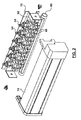
- the drive screw displaces a slider 30 whereas the splined rotatable shaft acts as a linear guide for the slider.
- the splined rotatable shaft 22 also functions to rotate an actuator within the slider to actuate a desired valve, i.e. to open or close a desired valve.
- the manifold housing 14 has a channel-like portion adapted to receive and retain a circuit board, e.g. a printed circuit board (PCB) on which various electronic sensors may be disposed.
- the PCB may include slider positioning sensors to sense a position of the slider.
- the PCB may include cross gear positioning sensors that sense the position (or angular orientation) of the cross gears (indicative of whether the valves are open or closed).
- the cross gear 40 attached to each respective valve has four semicircular receptacles or semicircular recesses 42 (or arc-shaped zones) for receiving the round tip of the actuator carried by the slider.
- On each side of the receptacles 42 are concave surfaces 46 that terminate in one of four pointed tips 44 .
- This construction ensures that the actuator cannot get stuck on the cross gear. In other words, regardless where the actuator engages along the surface of the cross gear, the actuator will be forced into proper engagement with one of the four receptacles 42 . Because the valves in the manifold are in a linear arrangement, the actuator can be moved to access any desired valve by simply translating the slider back and forth using the screw drive. Since the valves are quarter-turn valves, it does not matter whether the actuator engages from the left or from the right to either open or close any given valve.
- the pivot arm 35 is rotationally movable from a retracted position inside the slider housing 31 to an extended position protruding from the slider housing 31 .
- the pivoting arm 35 pivots about a pivot axis defined by a transverse bore 35 a in the pivot arm that receives a pivot shaft 35 b or pin that is rotationally supported by holes in the slider housing (as shown in FIG. 10A ).
- the pivoting arm 35 that holds the actuator 34 comprises an internally splined cam 36 aligned with the splined inserts 33 .
- the splined cam 36 rotates with the splined shaft to cause the pivoting arm to pivot about a pivot axis, thereby causing the actuator to protrude (or refract) from the slider housing.
- the actuator 34 may include a cylindrical roller bearing 34 a (in the form of an annulus) fastened by a threaded fastener 34 b to the pivoting arm 35 .
- the bearing 34 a in the illustrated embodiment has a diameter that matches that of the semicircular recesses in the cross gear.
- the bearing 34 a may be mounted over a spacer 34 c (or equivalent circular lip or ridge) as shown by way of example in FIG. 10A to space the bearing from the pivot arm 35 .
Landscapes
- Engineering & Computer Science (AREA)
- General Engineering & Computer Science (AREA)
- Mechanical Engineering (AREA)
- Physics & Mathematics (AREA)
- Thermal Sciences (AREA)
- Chemical & Material Sciences (AREA)
- Combustion & Propulsion (AREA)
- Multiple-Way Valves (AREA)
- Mechanically-Actuated Valves (AREA)
Priority Applications (1)
| Application Number | Priority Date | Filing Date | Title |
|---|---|---|---|
| US15/661,832 US10408468B2 (en) | 2015-10-06 | 2017-07-27 | Supply manifold with rotatable slider |
Applications Claiming Priority (2)
| Application Number | Priority Date | Filing Date | Title |
|---|---|---|---|
| CA2908193 | 2015-10-06 | ||
| CA2908193A CA2908193C (fr) | 2015-10-06 | 2015-10-06 | Collecteur d'alimentation dote d'une glissiere pivotante |
Related Child Applications (1)
| Application Number | Title | Priority Date | Filing Date |
|---|---|---|---|
| US15/661,832 Continuation US10408468B2 (en) | 2015-10-06 | 2017-07-27 | Supply manifold with rotatable slider |
Publications (2)
| Publication Number | Publication Date |
|---|---|
| US20170102152A1 US20170102152A1 (en) | 2017-04-13 |
| US9803876B2 true US9803876B2 (en) | 2017-10-31 |
Family
ID=58468369
Family Applications (2)
| Application Number | Title | Priority Date | Filing Date |
|---|---|---|---|
| US14/877,661 Active US9803876B2 (en) | 2015-10-06 | 2015-10-07 | Supply manifold with rotatable slider |
| US15/661,832 Active 2035-10-20 US10408468B2 (en) | 2015-10-06 | 2017-07-27 | Supply manifold with rotatable slider |
Family Applications After (1)
| Application Number | Title | Priority Date | Filing Date |
|---|---|---|---|
| US15/661,832 Active 2035-10-20 US10408468B2 (en) | 2015-10-06 | 2017-07-27 | Supply manifold with rotatable slider |
Country Status (7)
| Country | Link |
|---|---|
| US (2) | US9803876B2 (fr) |
| EP (1) | EP3180554B1 (fr) |
| CA (2) | CA2948712C (fr) |
| DK (1) | DK3180554T3 (fr) |
| PL (1) | PL3180554T3 (fr) |
| RU (1) | RU2667246C1 (fr) |
| WO (1) | WO2017059517A1 (fr) |
Cited By (4)
| Publication number | Priority date | Publication date | Assignee | Title |
|---|---|---|---|---|
| US20190285286A1 (en) * | 2017-02-06 | 2019-09-19 | Malcolm MacDuff | Hydronic supply manifold |
| WO2020056482A1 (fr) * | 2018-09-21 | 2020-03-26 | Malcolm Macduff | Collecteur de double soupape automatisé |
| WO2020232525A1 (fr) * | 2019-05-17 | 2020-11-26 | Malcolm Macduff | Actionneur de soupape à tige quart de tour |
| US10921015B2 (en) | 2018-08-28 | 2021-02-16 | Johnson Controls Technology Company | Systems and methods for adjustment of heat exchanger position |
Families Citing this family (5)
| Publication number | Priority date | Publication date | Assignee | Title |
|---|---|---|---|---|
| US10690356B2 (en) * | 2016-04-13 | 2020-06-23 | Paul D Mercier, SR. | Enhanced convection, differential temperature managed, hydronic heating appliance |
| CN109386687B (zh) * | 2018-11-21 | 2020-05-01 | 王佳乐 | 一种地下管道紧急止水装置 |
| US20200393049A1 (en) * | 2019-06-13 | 2020-12-17 | Millard M. Minton, Jr. | Water control device |
| CN111927983A (zh) * | 2020-07-24 | 2020-11-13 | 上海紫新姗实业有限公司 | 一种地暖分水器支架 |
| CN116214112B (zh) * | 2023-04-20 | 2023-11-10 | 浙江艾柯暖通科技有限公司 | 一种分水器的阀体自动装配设备 |
Citations (23)
| Publication number | Priority date | Publication date | Assignee | Title |
|---|---|---|---|---|
| FR451039A (fr) * | 1912-01-31 | 1913-04-09 | Nicolas Fedorowitsch Von Ditma | Dispositif d'étanchéité pour robinets |
| US1990990A (en) * | 1933-02-09 | 1935-02-12 | Curtiss Aeroplane & Motor Co | Control lever and shafting |
| US2530581A (en) * | 1946-09-13 | 1950-11-21 | John L Markis | Control for zone heating systems |
| US4034613A (en) * | 1974-07-08 | 1977-07-12 | Halfhill Martin O | Disc drive linear actuator and control system therefor |
| US4073468A (en) * | 1976-09-16 | 1978-02-14 | Erwin Robert L | Rotary plug valve |
| US4159651A (en) * | 1977-05-09 | 1979-07-03 | Baldwin-Gegenheimer Corporation | Flexure positioning mechanism |
| US4274802A (en) * | 1978-01-31 | 1981-06-23 | Fujitsu Fanuc Limited | Automated device |
| US4617957A (en) * | 1983-07-25 | 1986-10-21 | Xomox Corporation | Rotary plug valve |
| US4687941A (en) * | 1984-01-11 | 1987-08-18 | Alkem Gmbh | Glove box |
| US4905913A (en) * | 1988-04-19 | 1990-03-06 | Devilbiss Gmbh | Contour following apparatus for positioning spray guns |
| US5044606A (en) * | 1990-05-31 | 1991-09-03 | The United States Of America As Represented By The United States Department Of Energy | Valve stem and packing assembly |
| US5111997A (en) * | 1989-11-21 | 1992-05-12 | Taikisha, Ltd. | Automatic spray painting machine |
| US5445674A (en) * | 1992-03-06 | 1995-08-29 | The Pillsbury Company | Device for dispensing thixotropic sauce onto pizza crusts |
| US5482212A (en) * | 1994-07-05 | 1996-01-09 | Kobryn; Scott | Vehicle washing machine |
| US5735307A (en) | 1996-02-27 | 1998-04-07 | Dahl Brothers Canada Limited | Valve interchangeable between angle and straight |
| CN2837652Y (zh) | 2005-06-30 | 2006-11-15 | 东风汽车有限公司 | 多功能管接头 |
| US7162884B2 (en) * | 2003-03-21 | 2007-01-16 | Home Comfort Zones | Valve manifold for HVAC zone control |
| US20080073287A1 (en) * | 2006-09-27 | 2008-03-27 | Kolber John J | Chassis assembly |
| US20080141802A1 (en) * | 2006-10-30 | 2008-06-19 | Theodore Smick | Substrate scanner apparatus |
| JP2008291772A (ja) | 2007-05-25 | 2008-12-04 | Denso Corp | バルブリフト制御装置のアクチュエータ |
| US20110120241A1 (en) * | 2006-05-09 | 2011-05-26 | Sys Tec S.R.L. | System for Moving a Carriage Along a Guide |
| US8555926B2 (en) * | 2010-08-31 | 2013-10-15 | Malcolm MacDuff | Supply manifold for hydronic system |
| US20140144259A1 (en) * | 2011-04-07 | 2014-05-29 | American Axle & Manufacturing, Inc. | Two position actuator with sensing and control |
Family Cites Families (9)
| Publication number | Priority date | Publication date | Assignee | Title |
|---|---|---|---|---|
| US1671603A (en) * | 1926-04-29 | 1928-05-29 | Merco Nordstrom Valve Co | Valve |
| US2285221A (en) * | 1940-06-07 | 1942-06-02 | Mueller Co | Valve |
| US2510494A (en) * | 1945-08-20 | 1950-06-06 | Mueller Co | Valve |
| NL81408C (fr) * | 1951-04-13 | |||
| US4305567A (en) * | 1977-08-29 | 1981-12-15 | Rockwell International Corporation | Valve stem seal |
| SU1267844A1 (ru) * | 1983-04-08 | 1994-08-30 | Донецкий научно-исследовательский институт черной металлургии | Пробковый кран |
| US4878652A (en) * | 1986-05-09 | 1989-11-07 | The United States Of America As Represented By The United States Department Of Energy | Plug valve |
| US5937890A (en) * | 1998-01-09 | 1999-08-17 | Griswold Controls, Inc. | Insert for flow throttling ball valves |
| JP2008089103A (ja) * | 2006-10-03 | 2008-04-17 | Smc Corp | 手動切換弁 |
-
2015
- 2015-10-06 CA CA2948712A patent/CA2948712C/fr active Active
- 2015-10-06 CA CA2908193A patent/CA2908193C/fr active Active
- 2015-10-07 US US14/877,661 patent/US9803876B2/en active Active
- 2015-11-24 PL PL15899909T patent/PL3180554T3/pl unknown
- 2015-11-24 RU RU2017131444A patent/RU2667246C1/ru active
- 2015-11-24 EP EP15899909.4A patent/EP3180554B1/fr active Active
- 2015-11-24 DK DK15899909.4T patent/DK3180554T3/da active
- 2015-11-24 WO PCT/CA2015/051219 patent/WO2017059517A1/fr active Application Filing
-
2017
- 2017-07-27 US US15/661,832 patent/US10408468B2/en active Active
Patent Citations (23)
| Publication number | Priority date | Publication date | Assignee | Title |
|---|---|---|---|---|
| FR451039A (fr) * | 1912-01-31 | 1913-04-09 | Nicolas Fedorowitsch Von Ditma | Dispositif d'étanchéité pour robinets |
| US1990990A (en) * | 1933-02-09 | 1935-02-12 | Curtiss Aeroplane & Motor Co | Control lever and shafting |
| US2530581A (en) * | 1946-09-13 | 1950-11-21 | John L Markis | Control for zone heating systems |
| US4034613A (en) * | 1974-07-08 | 1977-07-12 | Halfhill Martin O | Disc drive linear actuator and control system therefor |
| US4073468A (en) * | 1976-09-16 | 1978-02-14 | Erwin Robert L | Rotary plug valve |
| US4159651A (en) * | 1977-05-09 | 1979-07-03 | Baldwin-Gegenheimer Corporation | Flexure positioning mechanism |
| US4274802A (en) * | 1978-01-31 | 1981-06-23 | Fujitsu Fanuc Limited | Automated device |
| US4617957A (en) * | 1983-07-25 | 1986-10-21 | Xomox Corporation | Rotary plug valve |
| US4687941A (en) * | 1984-01-11 | 1987-08-18 | Alkem Gmbh | Glove box |
| US4905913A (en) * | 1988-04-19 | 1990-03-06 | Devilbiss Gmbh | Contour following apparatus for positioning spray guns |
| US5111997A (en) * | 1989-11-21 | 1992-05-12 | Taikisha, Ltd. | Automatic spray painting machine |
| US5044606A (en) * | 1990-05-31 | 1991-09-03 | The United States Of America As Represented By The United States Department Of Energy | Valve stem and packing assembly |
| US5445674A (en) * | 1992-03-06 | 1995-08-29 | The Pillsbury Company | Device for dispensing thixotropic sauce onto pizza crusts |
| US5482212A (en) * | 1994-07-05 | 1996-01-09 | Kobryn; Scott | Vehicle washing machine |
| US5735307A (en) | 1996-02-27 | 1998-04-07 | Dahl Brothers Canada Limited | Valve interchangeable between angle and straight |
| US7162884B2 (en) * | 2003-03-21 | 2007-01-16 | Home Comfort Zones | Valve manifold for HVAC zone control |
| CN2837652Y (zh) | 2005-06-30 | 2006-11-15 | 东风汽车有限公司 | 多功能管接头 |
| US20110120241A1 (en) * | 2006-05-09 | 2011-05-26 | Sys Tec S.R.L. | System for Moving a Carriage Along a Guide |
| US20080073287A1 (en) * | 2006-09-27 | 2008-03-27 | Kolber John J | Chassis assembly |
| US20080141802A1 (en) * | 2006-10-30 | 2008-06-19 | Theodore Smick | Substrate scanner apparatus |
| JP2008291772A (ja) | 2007-05-25 | 2008-12-04 | Denso Corp | バルブリフト制御装置のアクチュエータ |
| US8555926B2 (en) * | 2010-08-31 | 2013-10-15 | Malcolm MacDuff | Supply manifold for hydronic system |
| US20140144259A1 (en) * | 2011-04-07 | 2014-05-29 | American Axle & Manufacturing, Inc. | Two position actuator with sensing and control |
Non-Patent Citations (1)
| Title |
|---|
| International Search Report, dated Dec. 21, 2015 from corresponding International Application No. PCT/CA2015/051219, 12 pp. |
Cited By (6)
| Publication number | Priority date | Publication date | Assignee | Title |
|---|---|---|---|---|
| US20190285286A1 (en) * | 2017-02-06 | 2019-09-19 | Malcolm MacDuff | Hydronic supply manifold |
| US10845063B2 (en) * | 2017-02-06 | 2020-11-24 | Malcolm MacDuff | Hydronic supply manifold |
| US10921015B2 (en) | 2018-08-28 | 2021-02-16 | Johnson Controls Technology Company | Systems and methods for adjustment of heat exchanger position |
| WO2020056482A1 (fr) * | 2018-09-21 | 2020-03-26 | Malcolm Macduff | Collecteur de double soupape automatisé |
| WO2020232525A1 (fr) * | 2019-05-17 | 2020-11-26 | Malcolm Macduff | Actionneur de soupape à tige quart de tour |
| US11339894B2 (en) | 2019-05-17 | 2022-05-24 | Malcolm Macduff | Quarter-turn pin-valve actuator |
Also Published As
| Publication number | Publication date |
|---|---|
| EP3180554B1 (fr) | 2020-09-30 |
| DK3180554T3 (da) | 2020-11-23 |
| CA2948712C (fr) | 2018-09-11 |
| US20170321906A1 (en) | 2017-11-09 |
| US20170102152A1 (en) | 2017-04-13 |
| EP3180554A4 (fr) | 2018-09-05 |
| PL3180554T3 (pl) | 2021-03-08 |
| CA2948712A1 (fr) | 2017-04-06 |
| RU2667246C1 (ru) | 2018-09-18 |
| CA2908193A1 (fr) | 2017-04-06 |
| EP3180554A1 (fr) | 2017-06-21 |
| US10408468B2 (en) | 2019-09-10 |
| CA2908193C (fr) | 2017-12-19 |
| WO2017059517A1 (fr) | 2017-04-13 |
Similar Documents
| Publication | Publication Date | Title |
|---|---|---|
| US10408468B2 (en) | Supply manifold with rotatable slider | |
| EP3330582B1 (fr) | Vanne de régulation de débit à trois voies et dispositif de régulation de température la mettant en uvre | |
| CN107917246B (zh) | 具有改进的流体流动和控制的阀构件 | |
| US9523434B2 (en) | Flow passage switching valve | |
| US8555926B2 (en) | Supply manifold for hydronic system | |
| US11592115B2 (en) | Fluid valve | |
| US10845063B2 (en) | Hydronic supply manifold | |
| KR20180029312A (ko) | 미세유량조절밸브 | |
| WO2020056482A1 (fr) | Collecteur de double soupape automatisé | |
| US20150345649A1 (en) | Combined Control and Flow Sensing Valve | |
| CA2713962C (fr) | Collecteur d'amenee pour systeme a eau chaude | |
| KR101128975B1 (ko) | 유량 조절 밸브 | |
| US11339894B2 (en) | Quarter-turn pin-valve actuator | |
| EP3431848A1 (fr) | Vanne de commande | |
| US20210348691A1 (en) | Multi-way valve assemblies for flow control of a fluid | |
| KR200368360Y1 (ko) | 온수분배기용 밸브 |
Legal Events
| Date | Code | Title | Description |
|---|---|---|---|
| STCF | Information on status: patent grant |
Free format text: PATENTED CASE |
|
| CC | Certificate of correction | ||
| MAFP | Maintenance fee payment |
Free format text: PAYMENT OF MAINTENANCE FEE, 4TH YR, SMALL ENTITY (ORIGINAL EVENT CODE: M2551); ENTITY STATUS OF PATENT OWNER: SMALL ENTITY Year of fee payment: 4 |