EP3431848A1 - Vanne de commande - Google Patents
Vanne de commande Download PDFInfo
- Publication number
- EP3431848A1 EP3431848A1 EP17182598.7A EP17182598A EP3431848A1 EP 3431848 A1 EP3431848 A1 EP 3431848A1 EP 17182598 A EP17182598 A EP 17182598A EP 3431848 A1 EP3431848 A1 EP 3431848A1
- Authority
- EP
- European Patent Office
- Prior art keywords
- control valve
- disc
- rotatably mounted
- sensor
- flow
- Prior art date
- Legal status (The legal status is an assumption and is not a legal conclusion. Google has not performed a legal analysis and makes no representation as to the accuracy of the status listed.)
- Withdrawn
Links
Images


Classifications
-
- F—MECHANICAL ENGINEERING; LIGHTING; HEATING; WEAPONS; BLASTING
- F16—ENGINEERING ELEMENTS AND UNITS; GENERAL MEASURES FOR PRODUCING AND MAINTAINING EFFECTIVE FUNCTIONING OF MACHINES OR INSTALLATIONS; THERMAL INSULATION IN GENERAL
- F16K—VALVES; TAPS; COCKS; ACTUATING-FLOATS; DEVICES FOR VENTING OR AERATING
- F16K3/00—Gate valves or sliding valves, i.e. cut-off apparatus with closing members having a sliding movement along the seat for opening and closing
- F16K3/02—Gate valves or sliding valves, i.e. cut-off apparatus with closing members having a sliding movement along the seat for opening and closing with flat sealing faces; Packings therefor
- F16K3/04—Gate valves or sliding valves, i.e. cut-off apparatus with closing members having a sliding movement along the seat for opening and closing with flat sealing faces; Packings therefor with pivoted closure members
- F16K3/06—Gate valves or sliding valves, i.e. cut-off apparatus with closing members having a sliding movement along the seat for opening and closing with flat sealing faces; Packings therefor with pivoted closure members in the form of closure plates arranged between supply and discharge passages
- F16K3/08—Gate valves or sliding valves, i.e. cut-off apparatus with closing members having a sliding movement along the seat for opening and closing with flat sealing faces; Packings therefor with pivoted closure members in the form of closure plates arranged between supply and discharge passages with circular plates rotatable around their centres
- F16K3/085—Gate valves or sliding valves, i.e. cut-off apparatus with closing members having a sliding movement along the seat for opening and closing with flat sealing faces; Packings therefor with pivoted closure members in the form of closure plates arranged between supply and discharge passages with circular plates rotatable around their centres the axis of supply passage and the axis of discharge passage being coaxial and parallel to the axis of rotation of the plates
-
- F—MECHANICAL ENGINEERING; LIGHTING; HEATING; WEAPONS; BLASTING
- F16—ENGINEERING ELEMENTS AND UNITS; GENERAL MEASURES FOR PRODUCING AND MAINTAINING EFFECTIVE FUNCTIONING OF MACHINES OR INSTALLATIONS; THERMAL INSULATION IN GENERAL
- F16K—VALVES; TAPS; COCKS; ACTUATING-FLOATS; DEVICES FOR VENTING OR AERATING
- F16K31/00—Actuating devices; Operating means; Releasing devices
- F16K31/44—Mechanical actuating means
- F16K31/53—Mechanical actuating means with toothed gearing
- F16K31/535—Mechanical actuating means with toothed gearing for rotating valves
Definitions
- the present invention relates to a control valve providing an alternative to the complex control valves available on the marked today.
- the present invention also relates to a control valve that is compact and can be fully closed, regulated in an accurate manner even in the low flow range and used to regulate flow in a large flow range.
- the control valve is intended for being used in HVAC installations or water or oil applications in general.
- Control valves are used in various applications for regulating the flow through pipe systems.
- a control valve typically comprises two separate structures: a valve assembly and an actuator that needs to be mechanically connected to the valve assembly. Accordingly, most prior art control valves are rather large and complex. This is a disadvantage in an application in which there is limited space available (e.g. in an integrated water circuit).
- a prior art control valve typically covers a limited flow range. Accordingly, several prior art control valves are needed to cover regulation of flow in a large flow range with the required accuracy. In practice, it is therefore required to produce more control valve variants to be able to cover a large flow range.
- control valve is a control valve comprising a housing provided with a first port and a second port and a passageway having a longitudinal axis provided therebetween, said control valve further comprising:
- the rotatably mounted disc is also referred to as the rotating disc.
- the control valve regulates the flow through it.
- the control valve comprising a housing provided with a first port (inlet port or outlet port) and a second port (inlet port or outlet port) and a passageway provided therebetween.
- the ports preferably extend perpendicular to the longitudinal axis of the housing.
- the ports may have any suitable geometry, including circular, oval, rectangular, hexagonal or octagonal.
- the ports may preferably be provided at the distal end of male fittings attached to the housing in their proximal end.
- the fittings are preferably provided with an outer thread and a flat face at the distal end portion.
- the housing is a sealed encasing without any potential leak points. This may be achieved by producing the housing in a closed metal housing provided with ports. It is preferred, that the part of the housing that encases the electronic part of the control valve is made of a non-metallic material (e.g. a plastic material).
- the control valve further comprises a rotatably mounted disc provided with one or more openings.
- the disc may have any desired geometry. It may be beneficial that two openings are provided in the rotatably mounted disc in order to distribute the pressure (exerted by the fluid flowing through the control valve) evenly.
- the one or two stationary mounted structures arranged adjacent to the rotatably mounted disc may have any suitable geometry.
- the one or two stationary mounted structures may be provided with one or more openings having any suitable geometry for allowing a flow through the one or two stationary mounted structures.
- the rotatably mounted disc and the stationary mounted structure(s) may comprise a ceramic material (e.g. be made in a ceramic material), a metal or plastic or combinations thereof.
- the actuator arranged inside the housing may be any suitable type of electrical actuator configured to rotate the rotatably mounted disc.
- the actuator may preferably be radially displaced relative to the rotatably mounted disc.
- the actuator will not take up space or block the passageway provided between the first port and the second port. Accordingly, it is possible to provide a control valve enabling a high maximum flowrate through the passageway.
- first port is aligned with the second port.
- second port it is possible to provide a compact control valve that can be installed in most existing pipe systems and replace existing control valves.
- the rotatably mounted disc is rotatably mounted on a shaft extending parallel to the longitudinal axis of the passageway.
- the rotatably mounted disc it is possible to arrange the rotatably mounted disc centrally in the passageway and thus provide a compact control valve.
- control valve is an inline-type control valve, wherein the fluid flows basically parallel to the longitudinal axis of the passageway. This means that the flow through the passageway extends along a basically straight path between the first port and the second port.
- Control valves having an inline configuration are beneficial in various situations. Moreover, it is possible to reduce the resistance in the control valve especially in the fully open configuration. Moreover, it is possible to provide a compact control valve.
- the rotatably mounted disc is rotatably mounted on a shaft extending parallel to the longitudinal axis. It may be beneficial that the longitudinal axis extends parallel to the direction of the flow. Hereby, the rotatably mounted disc can be moved entirely in a plane perpendicular to the direction of the flow. Thus, the size of the rotatably mounted disc and the one or two stationary mounted structures can be minimized. Accordingly, it is possible to provide a compact control valve.
- a gear is arranged at the circumference (e.g. the outer periphery) of the rotatably mounted disc.
- an engaging gear unit e.g. a worm gear
- a rack or a toothed belt e.g.
- the actuator comprises a motor shaft provided with a gear engaging with a gear of the rotatably mounted disc directly or through a series of gears.
- the shaft extending parallel to the longitudinal axis of the passageway is provided with a through-going channel.
- a sensor in fluid configuration with the through-going channel.
- a sensor is arranged and configured to detect the pressure of a fluid at the first port, the second port or in a chamber arranged in the passageway provided therebetween.
- a sensor is arranged and configured to detect the differential pressure between the first port and the second port or between two locations along the passageway provided therebetween.
- a sensor is arranged and configured to detect the temperature of a fluid flowing through the control valve.
- the senor is arranged and configured to detect:
- the senor is mounted within a mounting structure inside the housing, wherein a shaft protrudes from the mounting structure and a channel extending along the longitudinal axis of the control valve towards the second port, wherein the channel extends along the longitudinal axis of the control valve towards the first port.
- the sensor it is possible to apply the sensor as a differential pressure sensor detecting the differential pressure across the control valve.
- control valve may be an advantage to provide the control valve with a differential pressure sensor that is in fluid communication with both the first port through the channel and with the second port through the channel.
- sensor it is possible to apply the sensor as a differential pressure sensor to detect the pressure drop across the control valve.
- the shaft is provided with a channel being in fluid communication with the second chamber and the sensor and/or wherein the channel is in fluid communication with the sensor and the first chamber.
- the senor is electrically connected to an electronic component arranged in the housing.
- the electronic component preferably comprises a control unit or is connected to a control unit either arranged in the housing or outside the housing.
- the rotating disc is sandwiched between two stationary discs, wherein the rotating disc and the two stationary discs constitute a disc assembly, wherein said discs are provided with openings for allowing a fluid to pass through the disc assembly.
- the adjacent structures the stationary discs
- it is possible to produce the adjacent structures (the stationary discs) in another material than the housing.
- It may be an advantage to produce the rotating disc and the two stationary discs in the same material e.g. in a ceramic material or another wear resistant material and produce the housing in another materiel a such as metal or plastic (e.g. fibre-reinforced plastic).
- the rotating disc abuts a stationary disc, wherein said rotating disc and stationary disc constitute a disc assembly, wherein said discs are provided with openings for allowing a fluid to pass through the disc assembly.
- one or more gaskets or sealing rings are arranged to seal the mounting structure against the inside surface of the wall of the housing. It may be beneficial that one or more gaskets or sealing rings are arranged to seal the mounting structure against the stationary disc arranged in the shortest distance from the first port.
- a gasket or a sealing ring is arranged in an annular groove for sealing the stationary disc against the inside surface of the wall of the housing.
- the rotatably mounted disc and the one or two stationary mounted structures are shaped to form a control valve having an equal percentage characteristic. It may be beneficial that the rotatably mounted disc and the one or two stationary mounted structures are shaped to form a control valve having a modified equal percentage characteristic.
- An equal percentage characteristic is essentially an exponential relationship between the degree of opening (stroke) in percentage and the area or flow through the valve in percentage. This is done to achieve small flows as well as large flow; and to have small incremental change of flow at small flows, where it is necessary; and have large incremental change of flow at large flows, where it is acceptable. Since the valve is required to close completely to deliver a zero flow, it is a fundamental challenge that an exponential relationship never reaches zero. Accordingly, it is necessary to make a modification of the equal percentage characteristic that enables complete close-off of the valve.
- control valve comprises a control unit configured to receive absolute pressure and/or relative pressure and/or differential pressure data from one or more sensing members and regulate the flow in a pressure independent manner.
- Pressure independent control valves can provide automatic flow regulation to maintain a constant flow of a fluid (e.g. hot or chilled water) regardless of system pressure changes.
- Pressure independent control valves are used in many closed loop heating, ventilation and air conditioning (HVAC) applications.
- pressure independent control valves regulate and maintain a constant flow as the fluid pressure in the system varies with the changing loads. This provides better comfort and increases the energy efficiency. Accordingly, pressure independent valves allow the system to perform better. With the desired flow delivered to each coil, boilers and chillers are most efficient in closed loop HVAC applications. Therefore, as pressure independent control valves deliver a constant flow even as loads change and valves in the system open and close using them makes installation and commissioning simpler.
- control valve comprises a control unit configured to limit the maximum flowrate according to a predefined flow range. This is another way of commissioning the valve, which will further minimize the work for an installer commissioning the system.
- control valve comprises a control unit, preferably a build-in control unit, configured to modulate the flow according to one or more internally and/or externally provided control signals by using the actuator.
- control valve comprises a control unit configured to control the flow on the basis of differential pressure measurements.
- control valve is a differential pressure control valve.
- control valve comprises a control unit configured to receive sensor data from a sensor and control/regulate the actuator on the basis of these data and hereby regulate the angular position of the rotatably mounted disc and e.g. the differential pressure across the control valve.
- the sensor may be provided in the housing of the control valve.
- the sensor may be an external sensor arranged outside the housing. Several internally and/or externally arranged sensors may be provided inside or outside the housing, respectively.
- control unit is configured to receive a control signal input from an external source being a thermostat or a building management system.
- control valve comprises a control unit configured to provide a power estimation based on flow measurements made by a sensor integrated in the housing and temperature information, preferably temperature measurements made by a sensor in the control valve and an additional externally arranged temperature sensor.
- control valve comprises an externally arranged temperature sensor configured to provide temperature measurements and send them to a control unit of the control valve.
- the control unit of the control valve may be integrated in the housing or be externally arranged (e.g. in an external box connected to the control valve).
- control valve is configured to detect the power and thus function as a heat meter and/or power meter.
- control valve comprises a sensor or an encoder configured and arranged to detect the configuration, preferably the angular position relative to a reference position, of the rotatably mounted disc.
- the control valve comprises a sensor or an encoder configured and arranged to detect the configuration, preferably the angular position relative to a reference position, of the rotatably mounted disc.
- the control valve according to the invention may comprise one or more wired or wireless communication modules, preferably arranged in an electronic component inside the housing or in an external control box. Any suitable wired or wireless communication protocol may be applied.
- control valve comprises a control signal module, configured to be compatible with any building management system.
- the control valve comprises a communication module configured to communicate by means of a wireless personal area network technology such as Bluetooth Low Energy.
- a wireless personal area network technology such as Bluetooth Low Energy.
- configuration such as commissioning of the valve is possible by using a smartphone.
- the control valve comprises a power loss module comprising an internal electrical power source such as a battery and a detection unit configured to detect the status of an external electrical power supply, wherein the detection unit is configured to detect a case of power loss (of the external electrical power supply) and wherein the detection unit is configured to perform an action in case of power loss (external electrical power supply).
- the action may be to close the control valve.
- the action may be to generate and send an alert and/or to activate an activation device.
- control valve comprises a power loss module comprising an internal power source, a detection unit configured to detect the power supply (or lack thereof), wherein the power loss module comprises a programmable/settable device configured to execute a predefined action in case of power failure.
- control valve comprises a sensor or an encoder configured and arranged to detect the configuration, preferably the angular position relative to a reference position, of the rotatably mounted disc.
- the configuration of the control valve e.g. on a continuous basis. Accordingly, the flow can be determined in an easy and accurate manner.
- control valve comprises a power loss module comprising an internal power source, a detection unit configured to detect the activity of the power supply (or lack thereof), wherein the power loss module comprises a programmable/settable device configured to execute a predefined action in case of power failure.
- control valve comprises an internal power source such as an energy harvesting device and an energy storage device configured to harvest and store energy continuously for continuous use in the control valve thus making it independent of any external power source.
- a control valve 2 of the present invention is illustrated in Fig. 1A .
- Fig. 1A illustrates a perspective view of a control valve 2 according to the invention
- Fig. 1B illustrates another perspective view of the control valve shown in Fig. 1A
- the control valve 2 comprises a housing 4 provided with a first fitting 12 and a second fitting 14.
- the first fitting 12 and the second fitting 14 are provided with a threaded portion 10.
- the first fitting 12 constitutes a first port
- the second fitting 14 constitutes a second port 8.
- the fittings 12, 14 are arranged in an inline configuration, and thus the valve control valve 2 is an inline control valve 2.
- Fig. 1C illustrates a side view of the control valve 2 shown in Fig. 1A and in Fig. 1B , wherein Fig. 1E illustrates a side view (seen from the opposite direction) of the control valve shown in Fig. 1C.
- Fig. 1D illustrates a front view of the control valve shown in Fig. 1A .
- the control valve 2 comprises an integrated actuator (see Fig. 2A and Fig. 3B ).
- the actuator may preferably be an electrical motor.
- the actuator is controlled by means of a control unit 78 integrated in the housing 4.
- the control unit 78 may be configured to receive one or more inputs, including sensor inputs.
- sensor inputs e.g. inputs from one or more sensors (e.g. a differential pressure sensor) arranged inside the housing.
- the actuator is controlled by means of a control unit 78 arranged outside the housing 4.
- the control unit 78 may be configured to receive one or more inputs, including sensor inputs.
- the control valve 2 can be regulated on the basis of sensor inputs e.g. inputs from one or more sensors configured to detect differential pressure, temperature, flow or combinations hereof.
- the control valve 2 may be electrically connected to a control box arranged outside the housing 4, by means of an electric cable.
- the control valve 2 may be electrically connected to an electric power source (e.g. the mains or another electrical power source) by a wired connection.
- the actuator may be powered by a battery and/or capacitor and/or energy harvester arranged inside the housing 4 or a battery and/or capacitor arranged outside the housing 4.
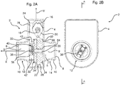
- Fig. 2A illustrates a cross-sectional view of a control valve 2 according to the invention
- Fig. 2B illustrates a front view of the control valve shown in Fig. 2A
- the section line for the cross-section is indicated with a dotted line in Fig. 2B .
- the control valve 2 corresponds to the one illustrated in Fig. 1A-Fig. 1E and comprises a housing 4 having a first fitting 12 and a second fitting 14 protruding from the housing 4.
- the fittings 12, 14 extend along the longitudinal axis X of the passageway 5 and perpendicular to the longitudinal axis Y of the housing 4.
- the fittings 12, 14 are provided with a threaded portion 10 arranged at the distal outside part of the fittings 12, 14, respectively.
- the first fitting 12 comprises a first port 6, wherein the second fitting 14 comprises a second port 8.
- the first port 6 and the second port 8 may be either an inlet port or an outlet port depending on the desired direction of the flow, since the control valve 2 does not have a predefined flow direction.
- a first chamber 9 is arranged adjacent to the first port 6, whereas a second chamber 9' is arranged adjacent to the second port 8.
- the chambers 9, 9' constitute separate portions of the passageway 5 of the control valve 2.
- the control valve 2 comprises a rotatably mounted disc 28 provided with openings 48, 48' (see Fig. 3B ).
- This rotating disc 28 is mounted on a shaft 54 extending along the longitudinal axis X of the passageway 5 of the control valve 2.
- the shaft 54 protrudes from a mounting structure 56 arranged inside the housing 4.
- a differential pressure sensor 40 is mounted within the mounting structure 56.
- a channel 36 extending along the longitudinal axis X of the passageway 5 of the control valve 2 is arranged in the mounting structure 56.
- the shaft 54 is provided with a centrally arranged channel 38 in fluid communication between the second port 8 and the differential pressure sensor 40.
- the differential pressure sensor 40 is in fluid communication with both the first port 6 (through the channel 36) and with the second port 8 (through the channel 38).
- the sensor 40 may be electrically connected to the electronic component 24 arranged in the housing 4.
- a control unit 78 being part of the electrical components 24 is provided inside the housing 4.
- the rotating disc 28 is sandwiched between two stationary discs 34, 34' each provided with openings for allowing a fluid to pass through the disc assembly 44 comprising the rotating disc 28 and the two stationary discs 34, 34'.
- Sealing members 32 are arranged to seal the mounting structure 56 against the inside surface of the wall of the housing 4 and against the stationary disc 34' arranged closest to the first port 6.
- a sealing member formed as a sealing ring 32 is arranged in the annular groove 58 to seal the stationary disc 34 against the inside surface of the wall of the housing 4.
- the rotating disc 28 is provided with an outer gear 22 configured to engage with a corresponding gear of an engaging part (see Fig. 3B ) attached to a shaft 18 of an actuator shaped as an electric motor 16 (e.g. a stepper motor).
- the motor 16 can be used to rotate the rotating disc 28 and hereby regulate the flow through the disc assembly 44 by changing the angular position of the openings provided in the rotating disc 28 and the stationary discs 34, 34'.
- the motor 16 may preferably be electrically connected to the electronic component 24 so that the electronic component 24 can be used to control the motor 16 and hereby the angular position of the rotating disc 28 in order to control the flow through the disc assembly 44 of the control valve 2.
- the motor 16 is attached to a plate-shape mounting 30 arranged inside the housing 4.
- a first passage 42 and a second passage 42' are provided in the mounting structure 56. These passages 42, 42' facilitate the flow through the control valve by reducing the resistance through the control valve 2.
- the rotating disc 28 is attached to a bearing mounted on the shaft 54, wherein the shaft 54 is a fixed (non-rotating) part.
- shaft 54 is rotatably mounted and the rotating disc 28 is fixed to the shaft 54.
- Both discs 34, 34' may be attached to a bearing attached to the shaft 54 or the shaft 56 extending through a through-bore provided in the discs 34, 34', wherein a gap is provided between the inner periphery of the through-bore of the discs 34, 34' and the shaft 56 for allowing free motion (rotation) of the shaft 56 extending through the through-bore of the discs 34, 34'.
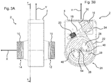
- Fig. 3A illustrates a side view of a control valve 2 according to the invention
- Fig. 3B illustrates a cross-sectional view of the control valve 2 shown in Fig. 3A
- the section line for the cross-section is indicated with a dotted line in Fig. 3A
- the control valve 2 comprises a housing 4 having a longitudinal axis Y.
- a first fitting 12 and a second fitting 14 extends along the longitudinal axis X of the control valve 2 and protrudes from the walls of the housing 4.
- the fittings 12, 14 extend perpendicular to the longitudinal axis Y of the housing 4.
- the distal outside part of the fittings 12, 14 are provided with a threaded portion 10.
- the first fitting 12 and the second fitting 14 constitute a first port 6 and a second port 8, respectively. Due to the fact that the control valve 2 does not have a predefined flow direction, the first port 6 and the second port 8 may be either inlet port or outlet port depending on the desired direction of the flow.
- the control valve 2 comprises a rotatably mounted disc 28 provided with openings 48, 48'. This rotating disc 28 is mounted on a shaft 54 provided with a centrally arranged channel 36 as explained with reference to Fig. 2A .
- the housing 4 comprises a hemicylindrical portion 26 and the rotating disc 28 is arranged in this part of the housing 4.
- an electrical component 24 is arranged in the opposite (upper) end of the housing 4.
- the electrical component 24 may comprise a control unit (see Fig. 2A ) configured to receive and process sensor signals and to control the motor 16. Even though not shown, the electrical component 24 may be electrically connected to the motor 16 and to one or more sensors arranged in the housing 4.
- the motor 16 may preferably be an electric stepper motor 16.
- the motor 16 comprises a shaft 18 and a worm gear 20 attached to the distal end of the motor shaft 18.
- the worm gear 20 is in engagement with the gear 22 provided at the periphery of the rotating disc 28. Accordingly, rotation of the motor shaft 18 will cause rotation of the rotating disc 28.
- the motor 16 can be used to regulate the angular position of the rotating disc 28. If the motor 16 is a stepper motor, it is possible to arrange the rotating disc 28 in a plurality of angular positions.
- the motor's position can be fixed or changed hereby maintaining or altering the angular position (and thus the size of the openings 48, 48' through the rotating disc 28 and its adjacent stationary discs) depending on the desired flow. It may be an advantage to apply a stepper motor 16 that divides a full rotation into a relative large number of equal steps in order to provide a large number of possible angular positions of the rotating disc 28.
- Fig. 4A illustrates a front view of a disc assembly 44 of a control valve according to the invention.
- Fig. 4B illustrates a side view of the disc assembly 44 shown in Fig. 4A
- Fig. 4C illustrates a perspective view of the disc assembly 44 shown in Fig. 4A .
- the disc assembly 44 comprises a centrally arranged rotating disc 28 sandwiched between a first adjacent disc 34 and a second adjacent disc 34'.
- the central ly arranged rotating disc 28 is rotatably mounted, whereas the adjacent discs 34, 34' are maintained in a fixed position. It is, however, possible to provide a rotation of the central disc 28 relative to the adjacent discs 34, 34' by rotating the adjacent discs 34, 34' and maintaining the centrally arranged rotating disc 28 in a fixed (angular) position.
- the three discs 28, 34, 34' are provided with a through-going centrally arranged bore 50 configured to receive a shaft.
- the shaft is fixed, whereas the centrally arranged rotating disc 28 is configured to rotate about the longitudinal axis of the shaft.
- the shaft may have a slightly smaller diameter than the inner diameter of the through-going centrally arranged bore 50 so that the centrally arranged rotating disc 28 can rotate freely about the shaft.
- the adjacent discs 34, 34' are provided with two opposing large openings 48", 48''' that each extend over approximately 90 degrees and hereby constitute an opening area close to a quarter of a circle each.
- the adjacent discs 34, 34' can furthermore be provided with minor grooves 52, 52', 52", 52''' for positioning the discs 34, 34'.
- the fluid flowing through a control valve according to the invention comprising the disc assembly 44 illustrated in Fig. 4A, Fig. 4B and Fig. 4C will flow through these openings 48", 48''' of the disc 34, the openings 48, 48' of the centrally arranged rotating disc 28 and the openings 48", 48''' of the disc 34'.
- the flow depends on the angular position of the centrally arranged rotating disc 28 relative to the adjacent discs 34, 34'.
- the area of the passage of the disc assembly 44 can be regulated from a closed position, in which the area of the passage of the disc assembly 44 is zero, to a fully open position, in which the area of the passage of the disc assembly 44 has its maximal magnitude, in the shown embodiment achieved at 90° rotation from the closed position.
- the control valve according to the invention may comprise a sensor or encoder (see Fig. 11D ) arranged to detect the configuration of the disc assembly 44.
- the control valve comprises a sensor or encoder arranged to detect the angular position of a centrally arranged rotatably mounted disc 28.
- the configuration of the disc assembly 44 detected by the sensor or encoder may be used to estimate the flow. Accordingly, the control valve may be configured to carry out flow estimation without having a flow sensor. It is, however, possible to integrate a flow sensor into the housing of the control valve. It is also possible to connect the control valve to an external flow sensor in order to apply the measured flow data.
- the centrally arranged rotating disc 28 as well as the adjacent discs 34, 34' are provided with recesses 46, 46', 46", 46''' distributed along the outer periphery of the discs 28, 34, 34'.
- the recesses 46, 46', 46", 46''' and the grooves 52, 52', 52", 52''' can be used to position and mount the disc assembly 44 in one or more receiving structures inside the housing of a control valve according to the invention.
- the adjacent discs 34, 34' are provided with an annular groove 58 configured to receive an O-ring (see Fig. 2A ) to seal the discs 34, 34' against an adjacent structure.
- the thickness T 2 of the centrally arranged rotating disc 28 is slightly larger than the thicknesses T 1 , T 3 of the adjacent discs 34, 34'.
- the central disc 28 as well as the adjacent discs 34, 34' have an outer periphery of the same geometry.
- the centrally arranged rotating disc 28 as well as the adjacent discs 34, 34' may be made in ceramic material, in metal or in a plastic material (e.g. a fibre-reinforced plastic material of a polymer matrix reinforced with fibres of glass, carbon, aramid or basalt).
- a plastic material e.g. a fibre-reinforced plastic material of a polymer matrix reinforced with fibres of glass, carbon, aramid or basalt.
- Fig. 4D illustrates a perspective view of another disc assembly 44 of a control valve according to the invention.
- the disc assembly 44 corresponds to the one shown in Fig. 4A, Fig. 4B and Fig. 4C except from the fact that the disc assembly 44 shown in Fig. 4D comprises only one adjacent disc 34.
- Fig. 5A illustrates a front view of a disc assembly 44 of a control valve according to the invention.
- Fig. 5B illustrates a side view of the disc assembly 44 shown in Fig. 5A
- Fig. 5C illustrates a perspective view of the disc assembly 44 shown in Fig. 5A .
- the disc assembly 44 comprises a centrally arranged rotating disc 28 sandwiched between a first adjacent disc 34 and a second adjacent disc 34'.
- the centrally arranged rotating disc 28 may be rotatably mounted, whereas the adjacent discs 34, 34' are maintained in a fixed position.
- rotation of the centrally arranged rotating disc 28 relative to the adjacent discs 34, 34' may be achieved by rotating the adjacent discs 34, 34' and maintaining the centrally arranged rotating disc 28 in a fixed angular position.
- the three discs 28, 34, 34' comprise a through-going centrally arranged bore 50 adapted to receive a shaft.
- the shaft may be a fixed (non-rotatable) structure, whereas the centrally arranged rotating disc 28 is arranged to rotate about the shaft. This can be accomplished by arranging a bearing inside the through-going centrally arranged bore 50 and attaching this bearing to the shaft or by applying a shaft having a slightly smaller diameter than the inner diameter of the through-going centrally arranged bore 50, hereby facilitating that the centrally arranged rotating disc 28 can rotate freely about the shaft.
- the adjacent discs 34, 34' are provided with two opposing large openings 48", 48''' that each extend over approximately 90 degrees and hereby each constitute an opening area close to a quarter of a circle.
- the flow through the disc assembly 44 and thus the control valve comprising it depends on the angular position of the central disc 28 relative to the adjacent discs 34, 34'.
- the area of the passage through the disc assembly 44 can be regulated. Accordingly, the area of the passage of the disc assembly 44 can be regulated between a closed position, in which the area of the passage of the disc assembly 44 is zero, to a fully open position, in which the area of the passage of the disc assembly 44 takes its maximum value.
- the centrally arranged rotating disc 28 is provided with two recesses 46, 46'.
- the two recesses 46, 46' are distributed along the outer periphery of the discs 28, 34, 34'.
- the recesses 46, 46' are configured to be used to position and mount the disc assembly 44 into one or more receiving structures inside the housing of a control valve according to the invention.
- Each of the adjacent discs 34, 34' are provided with an annular groove 58 configured to receive a sealing ring (like shown in Fig. 2A ) to seal the discs 34, 34' against an adjacent structure.
- the thickness T 2 of the centrally arranged rotating disc 28 basically corresponds to the thicknesses T 1 , T 3 of the adjacent discs 34, 34', whereas the centrally arranged rotating disc 28 has a slightly larger diameter than the adjacent discs 34, 34'.
- Fig. 6A illustrates a front view of a disc assembly 44 of a control valve according to the invention.
- Fig. 6B illustrates a side view of the disc assembly 44 shown in Fig. 6A
- Fig. 6C illustrates a perspective view of the disc assembly 44 shown in Fig. 6A .
- the disc assembly 44 comprises a centrally arranged rotating disc 28 sandwiched between a first adjacent disc 34 and a second adjacent disc 34'.
- the centrally arranged rotating disc 28 is configured to be rotatably mounted, whereas the adjacent discs 34, 34' are maintained in a fixed position.
- rotation of the centrally arranged rotating disc 28 relative to the adjacent discs 34, 34' is carried out by rotation of the adjacent discs 34, 34' while maintaining the centrally arranged rotating disc 28 in a fixed angular position.
- the three discs 28, 34, 34' comprise a through-going centrally arranged bore 50 adapted to receive a shaft extending through the three discs 28, 34, 34'.
- the shaft is a fixed structure, whereas the centrally arranged rotating disc 28 is arranged in a position, in which it can rotate about the shaft. This may be done by providing a bearing inside the through-going centrally arranged bore 50 and attaching the bearing to the shaft.
- the shaft may have a diameter being slightly smaller than the inner diameter of the through-going centrally arranged bore 50 so that the centrally arranged rotating disc 28 can rotate freely about the shaft.
- the adjacent discs 34, 34' are provided with two opposing openings 48", 48''' each extending over approximately 90 degrees.
- Regulation of the flow through the disc assembly 44 and thus the control valve into which the disc assembly 44 is arranged is carried out by controlling the angular position of the centrally arranged rotating disc 28 relative to the adjacent discs 34, 34'.
- the area of the passage through the disc assembly 44 can be controlled.
- the area of the passage of the disc assembly 44 can be minimised by bringing the disc assembly 44 in a closed position, in which the area of the passage of the disc assembly 44 is zero.
- the area of the passage of the disc assembly 44 can be gradually increased until the disc assembly 44 is brought into its fully open configuration, in which the area of the passage of the disc assembly 44 has its highest value.
- the adjacent discs 28, 34, 34' are provided with two recesses 46, 46'.
- the two recesses 46, 46' are distributed along the outer periphery of the discs 28, 34, 34'.
- the stationary discs are provided with positioning grooves 52, 52'.
- the recesses 46, 46' as well as the grooves 52, 52' are intended for being used for positioning and attachment of the disc assembly 44.
- Each of the adjacent discs 34, 34' are provided with an annular groove 58 configured to receive an O-ring for sealing the discs 34, 34' against an adjacent structure. Hereby, fluid leakage can be prevented.
- the thickness T 2 of the centrally arranged rotating disc 28 basically corresponds to the thicknesses T 1 , T 3 of the adjacent discs 34, 34'.
- the central disc 28 has a diameter that corresponds to the diameter of the adjacent discs 34, 34'.
- the centrally arranged rotating disc 28 as well as the adjacent discs 34, 34' may be made in a wear resistant material such as ceramic material, in metal or in a plastic material (e.g. a fibre-reinforced plastic material of a polymer matrix reinforced with fibres of glass, carbon, aramid or basalt).
- a wear resistant material such as ceramic material, in metal or in a plastic material (e.g. a fibre-reinforced plastic material of a polymer matrix reinforced with fibres of glass, carbon, aramid or basalt).
- Fig. 7A illustrates the flow characteristics (modified equal percentage and linear) of a disc assembly of preferred control valves according to the invention.
- Fig. 7A illustrates a first graph 60 (modified equal percentage characteristic) and a second graph 60' (linear characteristic) indicated by a dotted line depicting the area of the passage 64 of the disc assembly as function of the angular position 62 of a rotational disc.
- Fig. 7B-Fig. 7E illustrate front views of a disc assembly 44 according to the invention in various angular positions.
- the angular position ⁇ measured relative to a reference position (corresponding to a completely closed valve), is indicated.
- the disc assembly 44 comprises a rotatably mounted disc 28 arranged adjacent to an additional stationary mounted disc 34.
- the upper row illustrates front views of a disc assembly 44 configured to provide a modified equal percentage characteristic, whereas the lowermost row illustrates front views of a disc assembly 44 configured to provide a linear characteristic, respectively.
- Fig. 7B illustrates a front view of a disc assembly 44, according to the invention, in a configuration in which the angular position is 0°.
- the rotatably mounted disc 28 covers the first and second opening of the stationary mounted disc 34. Accordingly, the disc assembly 44 is arranged in a closed position. In this closed position, the disc assembly 44 is configured to entirely block the passage through the disc assembly 44, hereby providing a zero flow.
- Fig. 7C illustrates a front view of the disc assembly 44 shown in Fig. 7B , in a configuration in which the angular position is 30°.
- the rotatably mounted disc 28 covers the main portion of the first and second opening of the stationary mounted disc 34.
- a passage of the disc assembly 44 is established due to a first area A 1 and a second area A 2 that is not covered by the rotatably mounted disc 28. Therefore, the disc assembly 44 is arranged in a position in which the disc assembly 44 is configured to provide a low flow through the disc assembly 44.
- Fig. 7D illustrates a front view of the disc assembly 44 shown in Fig. 7B , in a configuration in which the angular position is 60°.
- the rotatably mounted disc 28 covers a major portion of the first and second opening of the stationary mounted disc 34.
- a moderate passage of the disc assembly 44 is provided by a first area A 1 and a second area A 2 that is not covered by the rotatably mounted disc 28. Consequently, the disc assembly 44 is arranged in a position in which the disc assembly 44 is configured to provide a moderate flow through the disc assembly 44.
- Fig. 7E illustrates a front view of the disc assembly 44 shown in Fig. 7B , in a configuration in which the angular position is 90°.
- the rotatably mounted disc 28 of the uppermost valve covers a minor portion of the first and second opening of the stationary mounted disc 34.
- a major passage of the disc assembly 44 is provided by a first area A 1 and a second area A 2 that is not covered by the rotatably mounted disc 28. Consequently, the disc assembly 44 of the uppermost valve is arranged in a position in which the disc assembly 44 is configured to provide a major flow through the disc assembly 44.
- the rotatably mounted disc 28 of the lowermost valve does not cover any portion of the first and second opening of the stationary mounted disc 34.
- the entire passage of the disc assembly 44 is provided by a first area A 1 and a second area A 2 not being covered by the rotatably mounted disc 28. Consequently, the disc assembly 44 of the lowermost valve is arranged in a position in which the disc assembly 44 is configured to provide maximum flow through the disc assembly 44.
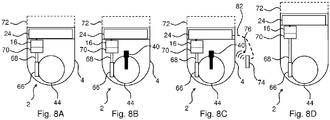
- Fig. 8A illustrates a schematic view of a control valve 2 according to the invention.
- the control valve 2 comprises a disc assembly 44 having a rotatably mounted disc provided with at least one opening and at least one stationary mounted structure (having one or more openings for allowing a flow through the at least one stationary mounted structure) arranged adjacent to the rotatably mounted disc.
- the control valve 2 comprises an actuator 16, preferably an electric actuator arranged inside the housing 4 of the control valve 2.
- the actuator 16 is configured to rotate the rotatably mounted disc and hereby regulate the flow through the control valve 2.
- the actuator may be an electric stepper motor.
- a connection member 68 (corresponding to the shaft 18 described with reference to Fig. 3B ) connects the actuator 16 and an engagement structure 66 (e.g. a gear) that is brought into engagement with the rotatably mounted disc or a structure (e.g. a worm gear 20 corresponding to the one previously described with reference to Fig. 3B ) mechanically connected thereto.
- a gear unit 70 is arranged to adjust (gear) the connection member 68. In one embodiment according to the invention, the gear unit 70 may be omitted.
- the control valve 2 comprises an electronic component 24, preferably comprising a motor controller.
- the electronic component 24 is arranged above the motor and is electrically connected to the motor 16.
- the add-on unit 72 may comprise a communication unit configured to communicate with one or more external devices (e.g. receive wireless signals transmitted by an external sensor).
- Fig. 8B illustrates a schematic view of a control valve 2 according to the invention.
- the control valve 2 almost corresponds to the one shown in Fig. 8A .
- the control valve 2 is provided with a sensor 40 arranged to detect a pressure parameter such as an absolute pressure, a relative pressure or a differential pressure.
- the sensor may be configured to detect temperature of the fluid flowing through the control valve 2.
- the sensor and the electronic component 24 may be adapted to detect and/or estimate the flow of the fluid flowing through the control valve 2.
- Fig. 8C illustrates a schematic view of a control valve 2 according to the invention.
- the control valve 2 basically corresponds to the one shown in Fig. 8B .
- the control valve 2 is, however, configured to receive wireless signals 76 from an external sensor 74.
- a wired connection 82 like indicated by the dotted line may be provided between the external sensor 74 and the control valve 2.
- the external sensor may be a temperature sensor, a pressure sensor or a flow sensor.
- Fig. 8D illustrates a schematic view of a control valve 2 according to the invention.
- the control valve 2 essentially corresponds to the one shown in Fig. 8A .
- the housing 4 of the control valve 2 is longer and the actuator 16 and the electronic component 24 is arranged in a larger distance from the disc assembly 44.
- control valve 2 can be used in application with high temperature and/or high pressure and/or highly corrosive media, since the actuator 16 and the electronic component 24 are arranged in a "safe position" in a distance from the media flowing through the control valve 2.
- Fig. 9A illustrates an exploded view of a disc assembly 44 according to the invention
- Fig. 9B illustrates another exploded view of the disc assembly 44 shown in Fig. 9A
- Fig. 9C illustrates a front view of the disc assembly 44 shown in Fig. 9A
- Fig. 9D illustrates a isometric side view of a rotatably mounted disc 28 shown in Fig. 9A and Fig. 9B
- Fig. 9E illustrates a close-up view of a channel provided in the opening 48" of the rotatably mounted disc 28.
- the disc assembly 44 comprises a centrally arranged rotatably mounted disc 28 sandwiched between a first stationary disc 34 and a second stationary disc 34'.
- the discs 28, 34, 34' are provided with recesses 46, 46', 46", 46''' provided along their periphery.
- the recesses 46, 46', 46", 46'' are intended to be used to position the discs 28, 34, 34' in a control valve according to the invention.
- the discs 28, 34, 34' are provided with a centrally arranged through-bore 50 that may receive a shaft.
- the first stationary disc 34 comprises openings 48", 48''' for allowing a flow to pass through the disc 34 and grooves 52, 52', 52", 52''' for positioning the disc 34.
- the second stationary disc 34' comprises openings 48", 48''' for allowing a flow to pass through the disc 34'.
- the rotatably mounted disc 28 comprises openings 48, 48' for allowing a flow to pass the disc 28. Each of these openings 48, 48' are provided with a channel 86 on one side, providing access to the "dead space" 48, 48' in the rotatably mounted disc 28 when the valve is closed.
- Fig. 10A, and Fig. 10D illustrate views of a control valve 2 according to the invention
- Fig. 10B illustrates a cross-sectional view of the control valve 2.
- the cross-section line is indicated in Fig. 10A .
- the control valve 2 comprises a motor housing 88 housing a motor 16 brought into engagement with a gear unit 70 arranged in the motor housing 88.
- the gear unit 70 is connected to a motor shaft 18 extending in a shaft sleeve 96.
- a worm gear 20 is provided in the distal end of the motor shaft 18.
- the worm gear is mechanically connected to the outer toothed periphery of a rotatably mounted disc 28 provided with two openings 48, 48'.
- the motor 16 is configured to rotate the rotatably mounted disc 28 and hereby alter the angular position of the rotatably mounted disc 28 in order to position the rotatably mounted disc 28 in a position relative to one or more adjacent stationary discs that provides a desired flow area through the openings 48, 48'.
- the control valve 2 shown in Fig. 10A, Fig. 10B and Fig. 10D is adapted to be used in a high temperature application: The electronic components can be kept safe and cold in the motor housing 88.
- Fig. 10C illustrates a further view of the control valve 2 shown in Fig. 10A in an installation.
- the control valve 2 comprises a motor housing 88 housing an electric motor connected to a motor shaft extending in a shaft sleeve 96.
- the control valve 2 comprises a first fitting 12, a second fitting 14 for fitting between two opposing flanges 90, 90'.
- the flanges are mechanically connected by bolts 92.
- the control valve 2 is configured to be used in high temperature applications, wherein the electronic components can be kept safe and relatively cold in the motor housing 88.
- the fittings 12, 14 are flanges matching the flanges 90, 90'.
- Fig. 11A illustrates a front view of a control valve 2 according to the invention
- Fig. 11B illustrates a cross-sectional view of the control valve 2 shown in Fig. 11A
- Fig. 11C illustrates a side view of the control valve 2 shown in Fig. 11A and Fig. 11B
- Fig. 11D illustrates a cross-sectional view of the control valve 2 shown in Fig. 11C .
- the control valve 2 comprises a motor housing 88 housing an electric motor 16 having a motor shaft 18 engaging a gear unit 70.
- An electronic component 24 provided with a control unit 78 (configured to control the motor 16 on the basis of one or more internal or external signals) is provided in the motor housing 88.
- Gears 70', 70", 20 are mechanically connected in order to transfer torque to an outer toothed portion (gear) 22 of a rotatably mounted disc 28 mounted on a shaft 54.
- the control valve 2 comprises a first fitting 12 provided with an outer threaded portion 10 and having a first port 6 and a second fitting 14 provided with an outer threaded portion 10 and having a second port 8.
- the control valve 2 comprises a rotatably mounted disc 28 provided with openings 48, 48' and being sandwiched between a first stationary disc 34 and a second stationary disc 34'. Chambers 9, 9' are provided in the passageway 5 provided between the ports 6, 8. Sealing rings 32 are provided to seal the first stationary disc 34 and a second stationary disc 34' against the housing 4 in which the discs 28, 34, 34' are arranged.
- a position sensor 80 is provided in the housing 4. The position sensor 80 is configured to detect the angular position of the rotatably mounted disc 28.
- the position sensor 80 is configured to send information about the angular position of the rotatably mounted disc 28 to the control unit 78. Accordingly, the control unit 78 can apply this information to regulate the motor 16 and control the angular position of the rotatably mounted disc 28.
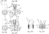
- Fig. 12A illustrates a front view of a control valve 2 according to the invention
- Fig. 12B illustrates a cross-sectional view of the control valve 2 shown in Fig. 12A
- Fig. 12C illustrates the control valve 2 shown in Fig. 12A from the other end
- Fig. 12D illustrates a cross-sectional view of the control valve 2 shown in Fig. 12C
- the control valve 2 basically corresponds to the one shown in Fig. 11A, Fig. 11B, Fig. 11C and Fig. 11D , however, the control valve 2 only comprises a single rotatably mounted disc 28 and a single stationary disc 34 arranged adjacent to it.
- an access point 94 to manual override is indicated.
- the access point 94 provides an engagement with one of the gears of the gear unit 70 to enable manual positioning of the rotatably mounted disc 28.
- Fig. 12E illustrates a side view of a control valve 2 according to the invention
- Fig. 12F illustrates a cross-sectional view of the control valve 2 shown in Fig. 12E
- the control valve 2 comprises a first fitting 12 having a first port 6 and a second fitting 14 having a second port 8 and a passageway 5 (having a first chamber 9 and a second chamber 9') provided therebetween.
- the flow F is indicated with solid lines.
- the flow F basically follows a straight patch. Accordingly, the control valve 2 is an inline type control valve 2.
Landscapes
- Engineering & Computer Science (AREA)
- General Engineering & Computer Science (AREA)
- Mechanical Engineering (AREA)
- Electrically Driven Valve-Operating Means (AREA)
Priority Applications (1)
| Application Number | Priority Date | Filing Date | Title |
|---|---|---|---|
| EP17182598.7A EP3431848A1 (fr) | 2017-07-21 | 2017-07-21 | Vanne de commande |
Applications Claiming Priority (1)
| Application Number | Priority Date | Filing Date | Title |
|---|---|---|---|
| EP17182598.7A EP3431848A1 (fr) | 2017-07-21 | 2017-07-21 | Vanne de commande |
Publications (1)
| Publication Number | Publication Date |
|---|---|
| EP3431848A1 true EP3431848A1 (fr) | 2019-01-23 |
Family
ID=59384058
Family Applications (1)
| Application Number | Title | Priority Date | Filing Date |
|---|---|---|---|
| EP17182598.7A Withdrawn EP3431848A1 (fr) | 2017-07-21 | 2017-07-21 | Vanne de commande |
Country Status (1)
| Country | Link |
|---|---|
| EP (1) | EP3431848A1 (fr) |
Cited By (2)
| Publication number | Priority date | Publication date | Assignee | Title |
|---|---|---|---|---|
| RU2799701C1 (ru) * | 2022-12-21 | 2023-07-10 | Акционерное общество "Ижевский электромеханический завод "Купол" | Заслонка регулируемая |
| DE102022004226A1 (de) | 2022-11-15 | 2024-05-16 | AMR Hydraulik Zwickau GmbH | Ventilsystem |
Citations (5)
| Publication number | Priority date | Publication date | Assignee | Title |
|---|---|---|---|---|
| US4674537A (en) * | 1985-03-20 | 1987-06-23 | American Standard Inc. | Straight-way & shut-off valve |
| EP0370557A1 (fr) * | 1988-11-22 | 1990-05-30 | Ems Holland B.V. | Débitmètre à gaz |
| US20060086923A1 (en) * | 2004-10-08 | 2006-04-27 | Marotta Controls, Inc. | Rotary valve and control system |
| DE102008042947A1 (de) * | 2008-10-20 | 2010-04-22 | Robert Bosch Gmbh | Ventil zur Steuerung von Volumenströmen |
| US20120192954A1 (en) * | 2011-01-31 | 2012-08-02 | Red Lion Bio-Energy Technologies | Rotating disc valve |
-
2017
- 2017-07-21 EP EP17182598.7A patent/EP3431848A1/fr not_active Withdrawn
Patent Citations (5)
| Publication number | Priority date | Publication date | Assignee | Title |
|---|---|---|---|---|
| US4674537A (en) * | 1985-03-20 | 1987-06-23 | American Standard Inc. | Straight-way & shut-off valve |
| EP0370557A1 (fr) * | 1988-11-22 | 1990-05-30 | Ems Holland B.V. | Débitmètre à gaz |
| US20060086923A1 (en) * | 2004-10-08 | 2006-04-27 | Marotta Controls, Inc. | Rotary valve and control system |
| DE102008042947A1 (de) * | 2008-10-20 | 2010-04-22 | Robert Bosch Gmbh | Ventil zur Steuerung von Volumenströmen |
| US20120192954A1 (en) * | 2011-01-31 | 2012-08-02 | Red Lion Bio-Energy Technologies | Rotating disc valve |
Cited By (2)
| Publication number | Priority date | Publication date | Assignee | Title |
|---|---|---|---|---|
| DE102022004226A1 (de) | 2022-11-15 | 2024-05-16 | AMR Hydraulik Zwickau GmbH | Ventilsystem |
| RU2799701C1 (ru) * | 2022-12-21 | 2023-07-10 | Акционерное общество "Ижевский электромеханический завод "Купол" | Заслонка регулируемая |
Similar Documents
| Publication | Publication Date | Title |
|---|---|---|
| KR101221574B1 (ko) | 유동 속도 또는 차압을 조절하기 위한 밸브 결합체 | |
| EP3812870B1 (fr) | Système de réglage de débit | |
| US20050016592A1 (en) | Process control valve | |
| US10619757B2 (en) | Valve and a method of controlling a valve in a fluid conduit | |
| US20130240045A1 (en) | Method for Determining a Fluid Flow Rate With a Fluid Control Valve | |
| US6352105B1 (en) | Servocontrolled valve for air-conditioning systems known as four pipe systems | |
| EP2715195B1 (fr) | Vanne d'équilibrage manuelle | |
| EP3180554B1 (fr) | Collecteur d'alimentation avec coulisseau rotatif | |
| BR9812378B1 (pt) | regualador de pressão auto ajustável, controlador eletrÈnico para um regulador de pressão, e, processo para compensar o desvio em um regulador de pressão. | |
| US10712221B2 (en) | Differential pressure meter | |
| JP7519111B2 (ja) | 流量制御スマート弁とこれを用いた流量制御システム | |
| EP2932164B1 (fr) | Registre à raccord direct sur extrémité ouverte à fixation rapide et actionneur | |
| EP3431848A1 (fr) | Vanne de commande | |
| WO2009039685A1 (fr) | Dispositif d'équilibrage d'écoulement automatique de haute précision | |
| US20180363801A1 (en) | Hydronic control valve | |
| US9500288B2 (en) | Combined control and flow sensing valve | |
| US10823296B2 (en) | Electric mixing valve with dual flowpath metering ball | |
| EP3669106B1 (fr) | Soupape de commande pour système de chauffage et/ou de refroidissement | |
| US20110303863A1 (en) | Combined changeover and control valve | |
| DE102017010891A1 (de) | Differenzdruckerfassungssystem, Rohrleitungseinheit, Verwendung einer Rohrleitungseinheit, Wärmeverteilsystem, Verwendung eines Wärmeverteilsystems und Verfahren | |
| US10047868B2 (en) | Adjustable curtain style port valve device | |
| CN112555461A (zh) | 一种新型多功能四通换向阀 | |
| US11946565B2 (en) | Valve assembly | |
| FI20225602A1 (en) | Valve unit for regulating the flow of heat transfer fluid and heating system |
Legal Events
| Date | Code | Title | Description |
|---|---|---|---|
| PUAI | Public reference made under article 153(3) epc to a published international application that has entered the european phase |
Free format text: ORIGINAL CODE: 0009012 |
|
| AK | Designated contracting states |
Kind code of ref document: A1 Designated state(s): AL AT BE BG CH CY CZ DE DK EE ES FI FR GB GR HR HU IE IS IT LI LT LU LV MC MK MT NL NO PL PT RO RS SE SI SK SM TR |
|
| AX | Request for extension of the european patent |
Extension state: BA ME |
|
| STAA | Information on the status of an ep patent application or granted ep patent |
Free format text: STATUS: THE APPLICATION IS DEEMED TO BE WITHDRAWN |
|
| 18D | Application deemed to be withdrawn |
Effective date: 20190724 |