US9798291B2 - Mechanical wristwatch bracelet with which an electronic function is associated - Google Patents
Mechanical wristwatch bracelet with which an electronic function is associated Download PDFInfo
- Publication number
- US9798291B2 US9798291B2 US15/215,799 US201615215799A US9798291B2 US 9798291 B2 US9798291 B2 US 9798291B2 US 201615215799 A US201615215799 A US 201615215799A US 9798291 B2 US9798291 B2 US 9798291B2
- Authority
- US
- United States
- Prior art keywords
- mechanical
- electronic
- executing
- function
- sensor
- Prior art date
- Legal status (The legal status is an assumption and is not a legal conclusion. Google has not performed a legal analysis and makes no representation as to the accuracy of the status listed.)
- Active
Links
Images


Classifications
-
- G—PHYSICS
- G04—HOROLOGY
- G04B—MECHANICALLY-DRIVEN CLOCKS OR WATCHES; MECHANICAL PARTS OF CLOCKS OR WATCHES IN GENERAL; TIME PIECES USING THE POSITION OF THE SUN, MOON OR STARS
- G04B37/00—Cases
- G04B37/0008—Cases for pocket watches and wrist watches
-
- G—PHYSICS
- G04—HOROLOGY
- G04G—ELECTRONIC TIME-PIECES
- G04G17/00—Structural details; Housings
- G04G17/02—Component assemblies
- G04G17/04—Mounting of electronic components
-
- A—HUMAN NECESSITIES
- A44—HABERDASHERY; JEWELLERY
- A44C—PERSONAL ADORNMENTS, e.g. JEWELLERY; COINS
- A44C5/00—Bracelets; Wrist-watch straps; Fastenings for bracelets or wrist-watch straps
-
- G—PHYSICS
- G01—MEASURING; TESTING
- G01H—MEASUREMENT OF MECHANICAL VIBRATIONS OR ULTRASONIC, SONIC OR INFRASONIC WAVES
- G01H11/00—Measuring mechanical vibrations or ultrasonic, sonic or infrasonic waves by detecting changes in electric or magnetic properties
-
- G—PHYSICS
- G01—MEASURING; TESTING
- G01R—MEASURING ELECTRIC VARIABLES; MEASURING MAGNETIC VARIABLES
- G01R27/00—Arrangements for measuring resistance, reactance, impedance, or electric characteristics derived therefrom
- G01R27/02—Measuring real or complex resistance, reactance, impedance, or other two-pole characteristics derived therefrom, e.g. time constant
- G01R27/26—Measuring inductance or capacitance; Measuring quality factor, e.g. by using the resonance method; Measuring loss factor; Measuring dielectric constants ; Measuring impedance or related variables
- G01R27/2605—Measuring capacitance
-
- G—PHYSICS
- G01—MEASURING; TESTING
- G01R—MEASURING ELECTRIC VARIABLES; MEASURING MAGNETIC VARIABLES
- G01R33/00—Arrangements or instruments for measuring magnetic variables
- G01R33/02—Measuring direction or magnitude of magnetic fields or magnetic flux
- G01R33/06—Measuring direction or magnitude of magnetic fields or magnetic flux using galvano-magnetic devices
-
- G—PHYSICS
- G04—HOROLOGY
- G04B—MECHANICALLY-DRIVEN CLOCKS OR WATCHES; MECHANICAL PARTS OF CLOCKS OR WATCHES IN GENERAL; TIME PIECES USING THE POSITION OF THE SUN, MOON OR STARS
- G04B1/00—Driving mechanisms
-
- G—PHYSICS
- G04—HOROLOGY
- G04B—MECHANICALLY-DRIVEN CLOCKS OR WATCHES; MECHANICAL PARTS OF CLOCKS OR WATCHES IN GENERAL; TIME PIECES USING THE POSITION OF THE SUN, MOON OR STARS
- G04B21/00—Indicating the time by acoustic means
-
- G—PHYSICS
- G04—HOROLOGY
- G04B—MECHANICALLY-DRIVEN CLOCKS OR WATCHES; MECHANICAL PARTS OF CLOCKS OR WATCHES IN GENERAL; TIME PIECES USING THE POSITION OF THE SUN, MOON OR STARS
- G04B23/00—Arrangements producing acoustic signals at preselected times
-
- G—PHYSICS
- G04—HOROLOGY
- G04B—MECHANICALLY-DRIVEN CLOCKS OR WATCHES; MECHANICAL PARTS OF CLOCKS OR WATCHES IN GENERAL; TIME PIECES USING THE POSITION OF THE SUN, MOON OR STARS
- G04B25/00—Indicating the time by other means or by combined means
- G04B25/02—Indicating the time by other means or by combined means by feeling; Clocks or watches for blind persons
- G04B25/04—Alarm clocks or watches with devices stimulating the skin
-
- G—PHYSICS
- G04—HOROLOGY
- G04B—MECHANICALLY-DRIVEN CLOCKS OR WATCHES; MECHANICAL PARTS OF CLOCKS OR WATCHES IN GENERAL; TIME PIECES USING THE POSITION OF THE SUN, MOON OR STARS
- G04B37/00—Cases
- G04B37/14—Suspending devices, supports or stands for time-pieces insofar as they form part of the case
- G04B37/1486—Arrangements for fixing to a bracelet
-
- G—PHYSICS
- G04—HOROLOGY
- G04C—ELECTROMECHANICAL CLOCKS OR WATCHES
- G04C21/00—Producing acoustic time signals by electrical means
-
- G—PHYSICS
- G04—HOROLOGY
- G04C—ELECTROMECHANICAL CLOCKS OR WATCHES
- G04C5/00—Electric or magnetic means for converting oscillatory to rotary motion in time-pieces, i.e. electric or magnetic escapements
-
- G—PHYSICS
- G04—HOROLOGY
- G04G—ELECTRONIC TIME-PIECES
- G04G13/00—Producing acoustic time signals
-
- G—PHYSICS
- G04—HOROLOGY
- G04G—ELECTRONIC TIME-PIECES
- G04G21/00—Input or output devices integrated in time-pieces
- G04G21/04—Input or output devices integrated in time-pieces using radio waves
-
- G—PHYSICS
- G06—COMPUTING; CALCULATING OR COUNTING
- G06T—IMAGE DATA PROCESSING OR GENERATION, IN GENERAL
- G06T7/00—Image analysis
- G06T7/20—Analysis of motion
Definitions
- the present invention concerns a watch case containing a mechanical timepiece movement and a watch bracelet or strap associated with the watch case in a removable manner, the watch bracelet containing an electronic device for performing an electronic function which supplements or improves the mechanical function(s) performed by the mechanical timepiece movement housed in the watch case.
- the object of watch bracelets of the aforementioned type, which incorporate electronic devices, is to offer at least one additional electronic function which adds to the functions performed by the mechanical watch movement.
- the execution of a mechanical function by the mechanical timepiece movement contained in the watch case is totally independent of the execution of an electronic function by the electronic device housed in the thickness of the bracelet or in the clasp closing the bracelet and vice versa, such that it is entirely possible to envisage associating a given bracelet with watch cases from different brands.
- the present invention concerns a wristwatch comprising a watch case in which is housed a mechanical timepiece movement comprising a mechanical device for executing at least a first mechanical function, the watch case being associated with a watch bracelet or strap in which is housed an electronic device arranged to execute at least a second electronic function, the execution of the second electronic function being dependent on the execution of the first mechanical function.
- the mechanical device for executing the first mechanical function is a mechanical striking device arranged to produce a first acoustic alarm signal
- the electronic device housed in the bracelet is arranged to produce a second acoustic alarm signal and/or a mechanical vibration, the electronic device being arranged to produce the second acoustic alarm signal at the moment when the mechanical striking device produces the first acoustic alarm signal. It is also possible to envisage offsetting in time, by a fixed duration or user-selectable duration, the activation of the second acoustic alarm signal.
- the present invention provides a mechanical wristwatch comprising a mechanical timepiece movement provided with a mechanical device which is arranged to execute a mechanical function and is associated with an electronic device housed in the thickness of the bracelet and arranged to execute an electronic function at the precise moment when the mechanical device of the mechanical timepiece movement executes the mechanical function. It is thus understood that, in such an arrangement, the mechanical timepiece movement acts as the master device and the electronic device housed in the bracelet acts as the slave device.
- a “mechanical wristwatch” means a wristwatch whose time-related and, where appropriate, non-time-related functions are ensured only by mechanical components which are supplied with the energy required for operation by one or more mainsprings.
- An “electronic device” means a device whose functions are ensured only by electrical or electronic components which are supplied with the energy required for operation by a battery or an accumulator which may be rechargeable.
- the mechanical device for executing a first mechanical function is a mechanical striking device arranged to produce a first acoustic alarm signal
- the electronic device housed in the bracelet is arranged to produce a second acoustic alarm signal and/or a mechanical vibration.
- the mechanical striking device emits its acoustic alarm signal
- the electronic device emits its own acoustic and/or mechanical alarm signal simultaneously, or after a delay.
- the electronic device housed in the bracelet thus makes it possible to improve the operating performance of the mechanical striking device, notably in terms of the acoustic power generated and the melody through the selection and combination of frequencies.
- This is very advantageous since, currently, the sound level produced by a timepiece movement equipped with a mechanical striking device is low, typically comprised between 65 and 75 dB at a distance of 40 cm. This is due, in particular, to dimensional and sound propagation constraints imposed by the geometry of the watch case and the material of which it is made, and to the limited amount of available mechanical energy, even in the case where the mechanical striking device is powered by a mainspring which is specific thereto.
- the duration of the acoustic alarm signal usually does not exceed 10 to 20 seconds, and a drop in the intensity of the acoustic signal is observed when the mainspring is almost completely let down.
- the electronic device for executing the second electronic function comprises an image sensor, typically of the CMOS type (complementary metal oxide semiconductor), arranged inside the bracelet to be under the transparent case back.
- CMOS type complementary metal oxide semiconductor
- the image sensor is arranged to scan, at close regular intervals, the indication provided by the mechanical striking mechanism. As soon as the image sensor detects the mechanical striking device starting and emitting the first acoustic alarm signal, it sends an electrical signal to an electronic control unit which actuates an electronic sound generator.
- the acoustic alarm signal produced by the mechanical striking device is reinforced by the electronic alarm signal, which makes it possible to increase acoustic power and thereby improve the audibility of the acoustic alarm signal produced by the mechanical wristwatch according to the invention. This can also enrich the sonority of the acoustic alarm produced by the mechanical device by creating a polyphonic sound.
- the image sensor In order for the image sensor to detect the moment at which the mechanical striking device starts to operate and produces the first acoustic alarm signal, the image sensor is arranged to scan, at close regular intervals, a component of the mechanical striking device which is normally immobile and which is only set in motion at the moment when the mechanical striking device emits the first acoustic signal.
- This component may be, for example, a strike pallets which pivots in a horizontal plane about its point of articulation.
- the electronic device for detecting the indication provided by the mechanical striking device comprises a capacitive, magnetic or inductive sensor.
- the capacitive sensor typically comprises an RC oscillator, a demodulator and an output stage.
- the operation of such a capacitive sensor occurs without any physical contact with the mechanical striking device and relies on an electric field change in its active area.
- the capacitive sensor disposed under the back of the watch case, detects a certain capacitance value which remains fixed as long as the mechanical striking device is at rest. At the moment when the mechanical striking device starts to operate and emits the first acoustic alarm signal, the capacitive sensor detects a capacitance change caused by the start of operation of the mechanical striking device, which causes a variation in the oscillation frequency of the RC circuit. Detection of this frequency variation generates an electrical output signal which is sent to the electronic control unit which actuates the electronic sound generator.
- the magnetic sensor detects a magnetic field change caused by the start of operation of the mechanical striking mechanism.
- this magnetic sensor may be a giant magnetoresistive sensor, for example marketed by the American company NVE and also known as a giant magnetoresistive digital switch or GMR.
- GMR giant magnetoresistive digital switch
- Magneoresistance is the property that some materials have to change the value of their electrical resistance when they are subjected to a magnetic field.
- a giant magnetoresistive sensor is arranged to output an electrical control signal as a function of a variation in the magnetic field to which it is subjected.
- the NVE sensor is a very low power sensor which works through transparent case backs (sapphire, Plexiglas, glass) or opaque non-magnetic case backs (stainless steel, titanium, aluminium, brass, ceramic, plastic). It may also be a reed switch with flexible reeds. To this end, at least one of the components of the mechanical striking device, which starts to move when the mechanical striking device starts to operate, is provided with a magnet. Thus, when the component moves, the magnet is moved concomitantly which, in the case of the reed switch, magnetizes the flexible contacts which attract each other and come into contact with each other. The reed switch is then closed and can send an electrical output signal to the electronic control unit which actuates the electronic sound generator.
- the inductive sensor conventionally comprises a winding made around a magnetic circuit whose role is to channel the magnetic field. At least one component of the mechanical striking device, which starts to move when the mechanical striking device starts to operate, is provided with a magnet. Thus, when the mechanical striking device starts to operate, the magnet moves and induces an electrical current in the winding of the inductive sensor. The inductive sensor sends an electrical output signal to the electronic control unit which actuates the electronic sound generator.
- the electronic device for detecting the indication provided by the mechanical striking device may comprise a simplified device comprising a microphone, which simply detects the acoustic wave produced by the start of operation of the mechanical striking device and sends an electrical signal to the electronic control unit which actuates the electronic sound generator.
- the mechanical device for executing the first mechanical function housed in the watch case comprises a mechanical indicator member which provides an indication as to whether the mechanical device for executing the first mechanical function is in a set or non-set state
- the electronic device comprises first means arranged to scan the indication provided by the mechanical indicator member and second means which are arranged to scan the moment at which the first mechanical function will start.
- FIG. 1 is a bottom view of an embodiment example of a wristwatch according to the invention comprising a watch case equipped with a bracelet having an electronic function.
- FIG. 2 is a perspective bottom view of the wristwatch of FIG. 1 .
- FIG. 3 is a perspective view of an embodiment example of the mechanical striking device.
- FIG. 4 a is a perspective view of the bracelet in which is housed the electronic device arranged to execute the second electronic function.
- FIG. 4 b is a larger scale view of the electronic device surrounded by a circle in FIG. 4 a.
- FIGS. 5, 6 and 7 schematically illustrate the assembly formed by the mechanical device arranged to produce the first acoustic alarm signal and the electronic device arranged to produce the second acoustic alarm signal according to whether the mechanical striking device is at rest, in operation, and then stopped again.
- FIGS. 8 and 9 are cross-sectional views respectively along the lines VIII-VIII and IX-IX of FIGS. 5 and 6 .
- FIG. 10 is a partial schematic view of the watch case according to the invention in the case where the back cover of the watch is opaque and non-electrically conductive and where the electronic device arranged to execute the second electronic function comprises a capacitive sensor.
- FIG. 11 is a partial schematic view of the wristwatch in the case where the back cover of the watch is opaque and non-electrically conductive and where the electronic device arranged to execute the second electronic function comprises a magnetic sensor.
- FIG. 12 is a partial schematic view of the wristwatch in the case where the back cover of the watch is opaque and non-electrically conductive and where the electronic device arranged to execute the second electronic function comprises an inductive sensor.
- FIG. 13 is a partial schematic view of the wristwatch in the case where the watch case comprises an opaque electrically conductive back cover and wherein the electronic device for detecting the indication provided by the mechanical striking device comprises a simplified device comprising a microphone, which detects the acoustic wave produced by the start of operation of the mechanical striking device and sends an electrical signal to the electronic control unit that controls the start of operation of the electronic sound generator.
- the electronic device for detecting the indication provided by the mechanical striking device comprises a simplified device comprising a microphone, which detects the acoustic wave produced by the start of operation of the mechanical striking device and sends an electrical signal to the electronic control unit that controls the start of operation of the electronic sound generator.
- FIG. 14 a is a partial schematic view of the wristwatch in the case where the mechanical striking device comprises a mechanical indicator member which indicates the non-set state of the mechanical striking device and wherein the electronic device comprises a light source and a light detector.
- FIG. 14 b is a similar view to that of FIG. 14 a in the case where the mechanical indicator member indicates the set state of the mechanical striking device and where the light emitted by the light source is reflected by the reflective surface portion of the mechanical indicator member towards the light detector.
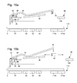
- FIG. 15 a is a partial schematic diagram of the wristwatch in the case where the mechanical striking device comprises a mechanical indicator member that indicates the non-set state of the mechanical striking device and wherein the electronic device comprises an image sensor having a first surface portion which is used to scan the indication provided by the mechanical indicator member, and a second surface portion used to scan the start of operation of the mechanical striking device.
- FIG. 15 b is a similar view to that of FIG. 15 a in the case where the mechanical indicator member moves aside, out of the field of vision of the image sensor when the mechanical striking device is set by the user.
- FIG. 16 a is a partial schematic view of the wristwatch of the invention in the case where the mechanical striking device comprises a mechanical indicator member which conceals the mechanical striking device when the latter is not set.
- FIG. 16 b is a similar view to that of FIG. 16 a in the case where the mechanical indicator member has moved aside.
- the present invention proceeds from the general inventive idea that consists in associating a mechanical wristwatch, devised to execute a first mechanical function in addition to the current time display, with a bracelet, in the thickness of which is housed an electronic device devised to execute a second electronic function, the execution of the second electronic function being dependent on by the execution of the first mechanical function.
- the mechanical wristwatch is arranged to emit a first acoustic alarm at a predetermined moment programmed by the user
- the electronic device housed in the bracelet is arranged to emit a second acoustic alarm and/or a mechanical vibration at the moment when the watch emits the first acoustic alarm.
- the wristwatch according to the invention comprises (see FIGS. 1 and 2 ) a watch case 2 devised to be worn on a user's wrist by means of a bracelet 4 .
- the base of watch case 2 is closed by a back cover 6 and the top is closed by a crystal 8 which covers a dial 10 above which move the hour hand 12 , minute hand 14 and seconds hand 16 for the current time display.
- dial 10 is illustrated transparently. It is evident, however, that for the purposes of the present invention, dial 10 is not required to be transparent and will preferably be opaque.
- a mechanical timepiece movement 18 devised to drive the current time display hands 12 , 14 , 16 , is housed in watch case 2 .
- This mechanical timepiece movement 18 further includes a mechanical device 20 arranged to produce at least a first mechanical function, for example to emit a first acoustic alarm signal.
- mechanical striking device 20 comprises a winding stem 22 which via first, second and third intermediate wheels 24 a , 24 b and 24 c , rotates a release wheel 26 .
- the tube of release wheel 26 carries or is kinematically connected to an index 28 seen in FIG. 1 , which can be placed facing the desired alarm time.
- the plate of release wheel 26 is pierced with three openings 30 placed on three different radii (see FIG. 9 ).
- An hour wheel 32 pivots above release wheel 26 and is pressed against release wheel 26 by a release lever 34 wound by a spring 36 .
- the plate of hour wheel 32 has three catches 38 , each provided with an inclined plane 40 .
- Hour wheel 32 driven by the movement, rotates and, at the set alarm time, the three catches 38 are positioned facing openings 30 and fall therein, such that hour wheel 32 is pressed against release wheel 26 .
- release lever 34 tilts upwards and releases a strike pallets 42 which, driven by a strike wheel 44 , starts to oscillate in a horizontal plane about its pivot point 46 (see FIG. 9 ).
- Strike wheel 44 which is directly driven by a strike barrel (not shown), acts like an escape wheel that drives strike pallets 42 .
- Strike pallets 42 carries a hammer 48 which strikes a pin fixed at the back of the case to sound the alarm.
- the end of a rocking lever 50 for winding the striking mechanism is in contact with a slide lever 52 which acts on a strike lock 54 .
- Strike lock 54 immobilises strike pallets 42 when winding stem 22 is in the time-setting position.
- an electronic device 56 housed in bracelet 4 is arranged to execute at least a second electronic function, for example to emit a second acoustic alarm signal and/or to produce a mechanical vibration, the execution of the second electronic function being dependent on the execution of the first mechanical function.
- electronic device 56 will emit the second acoustic alarm signal and/or produce a mechanical vibration at the moment when mechanical striking device 20 produces the first acoustic alarm signal.
- Mechanical striking device 20 housed in watch case 2 is thus the master of electronic device 56 which acts as the slave. It will be noted that the master function is not dependent on slave function and can operate normally even if the slave function is not in operation. It will also be noted that, according to a variant, it is possible to envisage offsetting, by a fixed duration, for example 5 or 10 seconds, or a duration selected by the user, the moment when electronic device 56 will start and produce the second acoustic signal.
- Electronic device 56 housed in bracelet 4 of wristwatch 1 comprises an image sensor 58 which scans, at close regular intervals, for the moment when mechanical striking device 20 starts to operate.
- Mechanical striking device 20 is initially at rest ( FIGS. 5 and 8 ).
- hour wheel 32 presses against release wheel 26 and release lever 34 , pressed against hour wheel 32 by spring 36 , pivots upwards, releasing strike pallets 42 , which starts to oscillate in the horizontal plane about its pivot point 46 .
- Hammer 48 carried by strike pallets 42 , follows the motion of the latter and strikes for example a pin.
- Image sensor 58 detects the start of motion of a movable element of the mechanical striking device, such as strike pallets 42 , and sends an electrical signal to a control unit 60 which will actuate an electronic sound generator 62 of the electromechanical or piezoelectric type.
- image sensor 58 is covered by a collimator lens 64 , and a light source 66 , such as a light emitting diode, illuminates the inside of watch case 2 through transparent case back 6 . All these electronic components are mounted on a printed circuit sheet 68 housed in the thickness of bracelet 4 and are powered by an electrical current source 70 .
- openings 72 and 74 are provided above image sensor 58 and light source 66 in the material forming bracelet 4 , so as to allow image sensor 58 to scan mechanical striking device 20 , and to allow light source 66 to illuminate the scene.
- Image sensor 58 is, for example, an image sensor marketed by ST Microelectronics under the reference VD5376. It has a thickness comprised between 180 ⁇ m and 725 ⁇ m, sides respectively measuring 1900 ⁇ m and 1932 ⁇ m and an active surface of 608 ⁇ 608 ⁇ m 2 formed of a 20 ⁇ 20 pixel matrix. Such an image sensor 58 is capable of detecting a change in the levels of grey in an image that it scans and thus of detecting, for example, the displacement of an object such as strike pallets 42 . It will be understood that image sensor 58 can detect the start of motion of another movable element, such as strike wheel 44 , or hammer 48 .
- another movable element such as strike wheel 44 , or hammer 48 .
- image sensor 58 Another change is observed by image sensor 58 when the first acoustic alarm signal stops and the movable element scanned by image sensor 58 stops ( FIG. 7 ). The image that image sensor 58 sees in fact becomes immobile again. Image sensor 58 then sends an electrical signal to control unit 60 which will stop electronic sound generator 62 .
- the duration of the second alarm in advance. Once started after the activation of the first alarm, the second alarm will stop independently once this time has elapsed
- FIGS. 5 and 6 a comparison of FIGS. 5 and 6 reveals that, in FIG. 6 , hour wheel 32 is pressed against release wheel 26 and that in FIG. 7 , hour wheel 32 has moved away from release wheel 26 again.
- electronic device 56 for detecting the indication provided by mechanical striking device 20 comprises a capacitive, magnetic or inductive sensor.
- a capacitive sensor 76 In the case of a capacitive sensor 76 ( FIG. 10 ), this typically comprises an RC oscillator 78 , a demodulator 80 and an output stage 82 .
- the operation of such a capacitive sensor 76 occurs without any physical contact with mechanical striking device 20 and relies on an electric field change in its active area.
- Capacitive sensor 76 disposed under the watch case back, detects a certain capacitance value which remains fixed as long as mechanical striking device 20 is at rest. At the moment when mechanical striking device 20 starts to operate and emits the first acoustic alarm signal, capacitive sensor 76 detects a capacitance change caused by the start of operation of the mechanical striking device 20 , which causes a change in the oscillation frequency of RC circuit 78 .
- the capacitive sensor may be the sensor marketed by the Swiss company EM-Microelectronic under the reference EM6420. This is a very low-power capacitive sensor able to operate with both transparent case backs (sapphire, Plexiglass, glass) and opaque non-metal case backs (plastic, ceramic).
- the EM6420 circuit must be connected to an electrode which will be placed inside the bracelet facing the metal part that will be set in motion when the alarm is activated.
- the magnetic sensor such as a GMR sensor marketed by NVE or a reed switch 84 with flexible reeds 86 , detects a change in the magnetic field caused by the start of operation of mechanical striking mechanism 20 .
- the magnetic sensor such as a GMR sensor marketed by NVE or a reed switch 84 with flexible reeds 86 .
- the magnetic sensor detects a change in the magnetic field caused by the start of operation of mechanical striking mechanism 20 .
- at least one of the components of mechanical striking device 20 for example strike pallets 42 , which starts to move when mechanical striking device 20 starts to operate, is provided with a magnet 88 .
- magnet 88 is moved concomitantly which magnetizes the flexible contacts 86 which attract each other and come into contact with each other.
- Reed switch 84 is then closed and can send an electrical output signal to electronic control unit 60 which actuates electronic sound generator 62 .
- inductive sensor 90 conventionally comprises a winding 92 made around a magnetic circuit 94 whose role is to channel the magnetic field.
- At least one component of mechanical striking device 20 for example strike pallets 42 , which starts to move when mechanical striking device 20 starts to operate, is provided with a magnet 88 .
- magnet 88 moves and induces an electrical current in winding 92 of inductive sensor 90 .
- Inductive sensor 90 sends an electrical output signal to electronic control unit 60 which actuates electronic sound generator 62 .
- the inductive sensor may comprise an LC oscillator circuit whose inductance will vary under the effect of the displacement of a metal component of the mechanical device.
- electronic device 56 for detecting the indication provided by mechanical striking device 20 may comprise a simplified device comprising a microphone 96 , which simply detects the acoustic wave produced by the start of operation of mechanical striking device 20 and sends an electrical signal to electronic control unit 60 which actuates electronic sound generator 62 .
- an accelerometer which will measure the activity of the mechanical striking device and detect the vibrations generated by hammer 48 at the moment when the mechanical striking device starts to operate.
- One accelerometer that is well suited to the requirements of the present invention is marketed under the reference ADXL362. This is a very low power circuit which constitutes an advantageous alternative to the microphone, particularly from the point of view of sealing and incorporation costs.
- electronic device 56 housed in bracelet 4 is arranged to execute at least a second electronic function, for example to emit a second acoustic alarm signal and/or to produce a mechanical vibration, the execution of the second electronic function being determined by the execution of the first mechanical function.
- electronic device 56 will emit the second acoustic alarm signal and/or produce a mechanical vibration at the moment when mechanical striking device 20 produces the first acoustic alarm signal.
- Mechanical timepiece mechanism 18 housed in watch case 2 is thus the master of electronic device 56 which acts as the slave.
- mechanical device 20 for executing the first mechanical function housed in watch case 2 , further comprises a mechanical indicator member 98 which provides an indication as to whether mechanical device 20 for executing the first mechanical function is in a set or non-set state.
- mechanical indicator member 98 will indicate that mechanical device 20 is set.
- mechanical indicator member 98 comprises a disc 100 having a first surface portion 100 a which is absorbent and a second surface portion 100 b which is reflective. This disc 100 is arranged to move between a first and a second position depending on whether mechanical device 20 is set or non-set.
- Electronic device 56 comprises a light source 102 such as a light emitting diode, and a light sensor 104 such as a photodiode, housed in bracelet 4 beneath disc 100 . The light emitted by light source 102 will thus be absorbed or reflected depending on whether it falls on absorbent surface portion 100 a or reflective surface portion 100 b of disc 100 .
- an image sensor 106 which may be of the same type as that described hereinbefore or simpler, scans for the moment when mechanical striking device 20 starts to operate.
- Light source 102 will, at regular intervals, send a light beam across disc 100 . If, due to the absence of signal provided by light sensor 104 , electronic device 56 observes that the light emitted by light source 102 falls on absorbent surface portion 100 a of disc 100 and is therefore absorbed, it concludes that mechanical striking device 20 is not set. Consequently, it is not necessary for image sensor 106 to scan for the moment when mechanical striking mechanism 20 starts to operate, which saves energy. Indeed, light source 102 illuminates disc 100 less often than image sensor 106 scans for the moment when striking device 20 starts to operate.
- disc 100 could be provided with a surface portion that reflects light towards light sensor 104 and a surface portion that reflects light in a direction in which light sensor 104 cannot sense light.
- the mechanical striking device comprises a mechanical indicator member 98 , of the type of a disc 108 that indicates the non-set state of the mechanical striking device
- electronic device 56 comprises an image sensor 110 of the type described hereinbefore having a first surface portion 110 a , which is used to scan the indication provided by mechanical indicator member 98 , and a second surface portion 110 b used to scan for the start of operation of mechanical striking device 20 .
- disc 108 is visible to the first surface portion 110 a of image sensor 110 when mechanical striking device 20 is in the non-set state, and then that disc 108 moves aside out of the field of vision of image sensor 110 when mechanical striking device 20 is set by the user ( FIG. 15 b ).
- electronic device 56 observes a change in the signal produced by image sensor 110 and will instruct image sensor 110 to scan mechanical striking device 20 by means of surface portion 110 b.
- the mechanical striking device includes a mechanical indicator member 112 which conceals mechanical striking device 20 from the view of image sensor 58 when said device is not set.
- mechanical indicator member 112 moves aside and control unit 60 detects a change in the signal provided by image sensor 58 .
- control unit 60 instructs image sensor 58 to scan mechanical striking device 20 to detect the start of operation thereof.
- the electronic device emits a second acoustic alarm signal or, equally, a mechanical vibration through the use of a vibrating mechanism housed in the thickness of the bracelet.
- the electronic device will activate the vibrating mechanism which will generate vibrations that the user will feel on his wrist.
- the vibrating mechanism is typically an eccentric mechanism which activates an inertia block.
- it may be envisaged to set the duration of the second alarm in advance. Once started after the activation of the first alarm, the second alarm will stop independently once this time has elapsed.
- the second alarm will be activated at the moment when the first alarm starts to operate and will stop at the end of a predefined time, independent of the duration of activation of the first alarm.
- the sensor is a microphone or an accelerometer
- the present invention also covers a method for generating an acoustic alarm signal in a wristwatch comprising a watch case 2 in which is housed a mechanical timepiece movement 18 comprising a mechanical striking device 20 arranged to produce a first acoustic alarm signal, watch case 2 being associated with a bracelet 4 in which is housed an electronic device 56 for producing a second acoustic alarm signal and/or a mechanical vibration, electronic device 56 being arranged to produce the second acoustic alarm signal at the moment when mechanical device 20 for executing the first mechanical function produces the first acoustic alarm signal or after a predefined duration or user-selectable duration following the start of operation of mechanical device 20 .
Landscapes
- Physics & Mathematics (AREA)
- General Physics & Mathematics (AREA)
- Engineering & Computer Science (AREA)
- Condensed Matter Physics & Semiconductors (AREA)
- Multimedia (AREA)
- Computer Vision & Pattern Recognition (AREA)
- Theoretical Computer Science (AREA)
- Acoustics & Sound (AREA)
- Electric Clocks (AREA)
- Electromechanical Clocks (AREA)
Applications Claiming Priority (3)
| Application Number | Priority Date | Filing Date | Title |
|---|---|---|---|
| EP15189552.1A EP3156854A1 (fr) | 2015-10-13 | 2015-10-13 | Montre-bracelet mecanique a laquelle est associee une fonction electronique |
| EP15189552.1 | 2015-10-13 | ||
| EP15189552 | 2015-10-13 |
Publications (2)
| Publication Number | Publication Date |
|---|---|
| US20170102672A1 US20170102672A1 (en) | 2017-04-13 |
| US9798291B2 true US9798291B2 (en) | 2017-10-24 |
Family
ID=54325398
Family Applications (1)
| Application Number | Title | Priority Date | Filing Date |
|---|---|---|---|
| US15/215,799 Active US9798291B2 (en) | 2015-10-13 | 2016-07-21 | Mechanical wristwatch bracelet with which an electronic function is associated |
Country Status (6)
| Country | Link |
|---|---|
| US (1) | US9798291B2 (fr) |
| EP (2) | EP3156854A1 (fr) |
| JP (1) | JP6228641B2 (fr) |
| KR (3) | KR20170043441A (fr) |
| CN (1) | CN106569403B (fr) |
| TW (1) | TWI701530B (fr) |
Families Citing this family (8)
| Publication number | Priority date | Publication date | Assignee | Title |
|---|---|---|---|---|
| SG11201900073YA (en) * | 2016-07-07 | 2019-02-27 | Guenat Sa Montres Valgine | Method and system for measuring and displaying data linked to a person's physical activity |
| JP6984472B2 (ja) * | 2018-02-14 | 2021-12-22 | セイコーエプソン株式会社 | 時計 |
| EP3556911A1 (fr) * | 2018-04-19 | 2019-10-23 | Comadur S.A. | Procédé de structuration d'un motif décoratif ou technique dans un objet réalisé en un matériau amorphe, semi-cristallin ou cristallin au moins partiellement transparent |
| TWI719636B (zh) * | 2019-09-16 | 2021-02-21 | 友達光電股份有限公司 | 穿戴式裝置及其操作方法 |
| EP3832405A1 (fr) * | 2019-12-06 | 2021-06-09 | Tissot S.A. | Montre comportant un système de contrôle d'accès biometrique à une donnée confidentielle |
| EP3832406A1 (fr) * | 2019-12-06 | 2021-06-09 | Tissot S.A. | Procédé de gestion de l'utilisation de données dans une montre |
| EP3832404A1 (fr) * | 2019-12-06 | 2021-06-09 | Tissot S.A. | Procédé de gestion de l'utilisation des fonctions d'une montre |
| CN114972344B (zh) * | 2022-07-29 | 2022-10-04 | 山东聊城中泰表业有限公司 | 一种用于手表零配件的生产质量缺陷检测方法 |
Citations (6)
| Publication number | Priority date | Publication date | Assignee | Title |
|---|---|---|---|---|
| US4601585A (en) * | 1985-11-18 | 1986-07-22 | Farley Brent L | Time display system |
| US5746501A (en) * | 1995-09-01 | 1998-05-05 | Chien; Tseng Lu | Portable object having a fastening band illuminated by a super thin lighting element |
| US7441415B2 (en) * | 1995-01-13 | 2008-10-28 | Philip John Radley-Smith | Bracelet |
| CN203812002U (zh) | 2013-12-31 | 2014-09-03 | 联芯科技有限公司 | 一种双屏幕智能手表 |
| US20160004276A1 (en) * | 2014-07-07 | 2016-01-07 | Christian Stroetmann | Wearable computer with time indications and movements |
| US20160306761A1 (en) * | 2015-04-15 | 2016-10-20 | Yuan-Hao Liu | Smart watch with transmission function |
Family Cites Families (20)
| Publication number | Priority date | Publication date | Assignee | Title |
|---|---|---|---|---|
| US3488565A (en) * | 1968-02-07 | 1970-01-06 | Erwin S Teltscher | Ultra-flat variable capacitor assembly |
| CN2101898U (zh) * | 1990-06-28 | 1992-04-15 | 烟台木钟厂 | 石英钟仿布谷鸟声报时装置 |
| JPH10282259A (ja) * | 1997-04-02 | 1998-10-23 | Seiko Epson Corp | 電子装置付携帯時計 |
| KR100308107B1 (ko) * | 1999-07-16 | 2001-09-13 | 박돈영 | 시계 타종장치 |
| JP2001059880A (ja) * | 1999-08-24 | 2001-03-06 | Komu Denshi Kaihatsu Kk | 目覚まし装置 |
| TW591353B (en) * | 2001-02-23 | 2004-06-11 | Asulab Sa | Portable object including means for activating an electronic function and method for controlling such an electronic function |
| JP2002318291A (ja) * | 2001-04-20 | 2002-10-31 | Rhythm Watch Co Ltd | 時計装置 |
| CN2502302Y (zh) * | 2001-09-03 | 2002-07-24 | 许家宝 | 机械钟机芯的打点控制机构 |
| CN2648476Y (zh) * | 2003-09-16 | 2004-10-13 | 上海泰华工艺礼品有限公司 | 振动报时手表 |
| EP1521141B1 (fr) * | 2003-10-01 | 2007-05-30 | Asulab S.A. | Pièce d'horlogerie ayant un mouvement mécanique associé à un régulateur électronique |
| JP2006220636A (ja) * | 2004-07-27 | 2006-08-24 | Matsushita Electric Works Ltd | 音波センサ |
| JP4500157B2 (ja) * | 2004-11-24 | 2010-07-14 | 株式会社神戸製鋼所 | 形状計測装置用光学系 |
| CN2791709Y (zh) * | 2005-04-10 | 2006-06-28 | 孙军 | 仿声提醒器 |
| JP2007212354A (ja) * | 2006-02-10 | 2007-08-23 | Seiko Instruments Inc | 時計の針位置検出装置及びこれを備えた時計 |
| DE602006020503D1 (de) * | 2006-07-10 | 2011-04-14 | Montres Breguet Sa | Musikmodul eines uhrwerks |
| CN200976094Y (zh) * | 2006-09-19 | 2007-11-14 | 彭玉成 | 一种新型手表 |
| EP2226688B1 (fr) * | 2009-03-05 | 2011-09-07 | Vaucher Manufacture Fleurier S.A. | Pièce d'horlogerie |
| CH707078A1 (fr) * | 2012-10-15 | 2014-04-15 | Société Anonyme De La Manufacture D Horlogerie Audemars Piguet & Cie | Timbre pour dispositif de sonnerie d'une pièce d'horlogerie. |
| CN104142623A (zh) * | 2013-05-06 | 2014-11-12 | 巨擘科技股份有限公司 | 腕表结构及腕表用的电子机芯 |
| EP2869140B1 (fr) * | 2013-10-30 | 2016-04-06 | The Swatch Group Research and Development Ltd. | Dispositif de détection de la position des aiguilles d'une montre |
-
2015
- 2015-10-13 EP EP15189552.1A patent/EP3156854A1/fr not_active Withdrawn
-
2016
- 2016-07-08 EP EP16178619.9A patent/EP3156855B1/fr active Active
- 2016-07-20 TW TW105122923A patent/TWI701530B/zh not_active IP Right Cessation
- 2016-07-21 US US15/215,799 patent/US9798291B2/en active Active
- 2016-08-25 JP JP2016164372A patent/JP6228641B2/ja active Active
- 2016-08-29 KR KR1020160110123A patent/KR20170043441A/ko active Search and Examination
- 2016-09-12 CN CN201610818807.5A patent/CN106569403B/zh active Active
-
2019
- 2019-02-08 KR KR1020190015096A patent/KR102000903B1/ko active IP Right Grant
- 2019-04-19 KR KR1020190046221A patent/KR102131555B1/ko active IP Right Grant
Patent Citations (6)
| Publication number | Priority date | Publication date | Assignee | Title |
|---|---|---|---|---|
| US4601585A (en) * | 1985-11-18 | 1986-07-22 | Farley Brent L | Time display system |
| US7441415B2 (en) * | 1995-01-13 | 2008-10-28 | Philip John Radley-Smith | Bracelet |
| US5746501A (en) * | 1995-09-01 | 1998-05-05 | Chien; Tseng Lu | Portable object having a fastening band illuminated by a super thin lighting element |
| CN203812002U (zh) | 2013-12-31 | 2014-09-03 | 联芯科技有限公司 | 一种双屏幕智能手表 |
| US20160004276A1 (en) * | 2014-07-07 | 2016-01-07 | Christian Stroetmann | Wearable computer with time indications and movements |
| US20160306761A1 (en) * | 2015-04-15 | 2016-10-20 | Yuan-Hao Liu | Smart watch with transmission function |
Non-Patent Citations (3)
| Title |
|---|
| David Szondy "Kairos TBand turns almost any watch into a smartwatch", XP055262033, http;//www.gizmag.com/Kairos-tband/34811/, 2014, 3 pages. |
| DAVID SZONDY: "Kairos TBand turns almost any watch into a smartwatch", 24 November 2014 (2014-11-24), pages 1 - 3, XP055262033, Retrieved from the Internet <URL:http://www.gizmag.com/kairos-tband/34811/> [retrieved on 20160401] |
| European Search Report dated Apr. 21, 2016 in European Application 15189552, filed on Oct. 13, 2015 ( with English Translation of Categories of Cited Documents and Written Opinion). |
Also Published As
| Publication number | Publication date |
|---|---|
| CN106569403B (zh) | 2019-08-16 |
| KR102131555B1 (ko) | 2020-07-08 |
| KR20190044600A (ko) | 2019-04-30 |
| US20170102672A1 (en) | 2017-04-13 |
| KR102000903B1 (ko) | 2019-07-16 |
| KR20170043441A (ko) | 2017-04-21 |
| EP3156855B1 (fr) | 2017-08-30 |
| JP2017075934A (ja) | 2017-04-20 |
| EP3156854A1 (fr) | 2017-04-19 |
| TW201716891A (zh) | 2017-05-16 |
| TWI701530B (zh) | 2020-08-11 |
| EP3156855A1 (fr) | 2017-04-19 |
| KR20190016531A (ko) | 2019-02-18 |
| CN106569403A (zh) | 2017-04-19 |
| JP6228641B2 (ja) | 2017-11-08 |
Similar Documents
| Publication | Publication Date | Title |
|---|---|---|
| US9798291B2 (en) | Mechanical wristwatch bracelet with which an electronic function is associated | |
| US7031228B2 (en) | Timepiece with touch-type reading and control of time data | |
| KR20100084972A (ko) | 전자제어기능 유발용 수단을 가진 시계와 같은 휴대용 물품 | |
| US7021819B2 (en) | Timepiece including a striking work | |
| US3462943A (en) | Alarm wristwatch | |
| JP7078704B2 (ja) | 機械式ムーブメントと表示される時間を補正するためのデバイスとを備える計時器 | |
| JP6644124B2 (ja) | 張られたチェーンを備えるリピーター機構 | |
| JP4522414B2 (ja) | 時計の非局在化された制御部材を作動させる機構を押圧する押しボタンが設けられる腕時計 | |
| RU2699928C1 (ru) | Репетирный механизм хронографа с предохранительной функцией | |
| CH711638B1 (fr) | Montre-bracelet mécanique à laquelle est associée une fonction électronique. | |
| GB2183870A (en) | Alarm timepiece | |
| JP2024523919A (ja) | 時計 | |
| CN115453844B (zh) | 具有局部照明的钟表 | |
| RU2526502C1 (ru) | Способ и устройство тактильной индикации текущего времени в часах и часы с тактильной индикацией текущего времени | |
| JP6961463B2 (ja) | 鳴鐘機構、携帯機器、ムーブメントおよび時計 | |
| RU134336U1 (ru) | Устройство тактильной индикации текущего времени в часах и часы с тактильной индикацией текущего времени | |
| US3849977A (en) | Device for regulating the hands of a timepiece | |
| JP3925173B2 (ja) | 時計 | |
| JP7446375B2 (ja) | 腕時計および時刻を修正するためのシステムを備える時計アセンブリ | |
| US11415939B2 (en) | Device for controlling the functions of a watch | |
| USRE26322E (en) | Electronically-controlled timepiece and motion transformer therefor | |
| EP1235122A1 (fr) | Objet portatif comprenant des moyens pour l'activation d'une fonction électronique et procédé de commande d'une telle fonction électronique | |
| JPH0675063A (ja) | 目覚し時計 | |
| JP2002318291A (ja) | 時計装置 |
Legal Events
| Date | Code | Title | Description |
|---|---|---|---|
| AS | Assignment |
Owner name: THE SWATCH GROUP RESEARCH AND DEVELOPMENT LTD, SWI Free format text: ASSIGNMENT OF ASSIGNORS INTEREST;ASSIGNORS:MARTIN, JEAN-CLAUDE;BORN, JEAN-JACQUES;CONUS, THIERRY;AND OTHERS;REEL/FRAME:039209/0273 Effective date: 20160707 |
|
| STCF | Information on status: patent grant |
Free format text: PATENTED CASE |
|
| MAFP | Maintenance fee payment |
Free format text: PAYMENT OF MAINTENANCE FEE, 4TH YEAR, LARGE ENTITY (ORIGINAL EVENT CODE: M1551); ENTITY STATUS OF PATENT OWNER: LARGE ENTITY Year of fee payment: 4 |