US9796128B2 - Filament winding device - Google Patents
Filament winding device Download PDFInfo
- Publication number
- US9796128B2 US9796128B2 US14/436,061 US201314436061A US9796128B2 US 9796128 B2 US9796128 B2 US 9796128B2 US 201314436061 A US201314436061 A US 201314436061A US 9796128 B2 US9796128 B2 US 9796128B2
- Authority
- US
- United States
- Prior art keywords
- tension
- liner
- fiber bundles
- unreeling
- bobbins
- Prior art date
- Legal status (The legal status is an assumption and is not a legal conclusion. Google has not performed a legal analysis and makes no representation as to the accuracy of the status listed.)
- Active, expires
Links
Images


Classifications
-
- B—PERFORMING OPERATIONS; TRANSPORTING
- B29—WORKING OF PLASTICS; WORKING OF SUBSTANCES IN A PLASTIC STATE IN GENERAL
- B29C—SHAPING OR JOINING OF PLASTICS; SHAPING OF MATERIAL IN A PLASTIC STATE, NOT OTHERWISE PROVIDED FOR; AFTER-TREATMENT OF THE SHAPED PRODUCTS, e.g. REPAIRING
- B29C53/00—Shaping by bending, folding, twisting, straightening or flattening; Apparatus therefor
- B29C53/56—Winding and joining, e.g. winding spirally
- B29C53/58—Winding and joining, e.g. winding spirally helically
- B29C53/60—Winding and joining, e.g. winding spirally helically using internal forming surfaces, e.g. mandrels
- B29C53/602—Winding and joining, e.g. winding spirally helically using internal forming surfaces, e.g. mandrels for tubular articles having closed or nearly closed ends, e.g. vessels, tanks, containers
-
- B—PERFORMING OPERATIONS; TRANSPORTING
- B29—WORKING OF PLASTICS; WORKING OF SUBSTANCES IN A PLASTIC STATE IN GENERAL
- B29C—SHAPING OR JOINING OF PLASTICS; SHAPING OF MATERIAL IN A PLASTIC STATE, NOT OTHERWISE PROVIDED FOR; AFTER-TREATMENT OF THE SHAPED PRODUCTS, e.g. REPAIRING
- B29C53/00—Shaping by bending, folding, twisting, straightening or flattening; Apparatus therefor
- B29C53/80—Component parts, details or accessories; Auxiliary operations
- B29C53/8008—Component parts, details or accessories; Auxiliary operations specially adapted for winding and joining
- B29C53/8016—Storing, feeding or applying winding materials, e.g. reels, thread guides, tensioners
-
- B—PERFORMING OPERATIONS; TRANSPORTING
- B65—CONVEYING; PACKING; STORING; HANDLING THIN OR FILAMENTARY MATERIAL
- B65H—HANDLING THIN OR FILAMENTARY MATERIAL, e.g. SHEETS, WEBS, CABLES
- B65H59/00—Adjusting or controlling tension in filamentary material, e.g. for preventing snarling; Applications of tension indicators
- B65H59/10—Adjusting or controlling tension in filamentary material, e.g. for preventing snarling; Applications of tension indicators by devices acting on running material and not associated with supply or take-up devices
- B65H59/20—Co-operating surfaces mounted for relative movement
- B65H59/26—Co-operating surfaces mounted for relative movement and arranged to deflect material from straight path
- B65H59/32—Co-operating surfaces mounted for relative movement and arranged to deflect material from straight path the surfaces being urged away from each other
-
- B—PERFORMING OPERATIONS; TRANSPORTING
- B65—CONVEYING; PACKING; STORING; HANDLING THIN OR FILAMENTARY MATERIAL
- B65H—HANDLING THIN OR FILAMENTARY MATERIAL, e.g. SHEETS, WEBS, CABLES
- B65H63/00—Warning or safety devices, e.g. automatic fault detectors, stop-motions ; Quality control of the package
- B65H63/06—Warning or safety devices, e.g. automatic fault detectors, stop-motions ; Quality control of the package responsive to presence of irregularities in running material, e.g. for severing the material at irregularities ; Control of the correct working of the yarn cleaner
- B65H63/061—Mechanical slub catcher and detector
-
- B—PERFORMING OPERATIONS; TRANSPORTING
- B29—WORKING OF PLASTICS; WORKING OF SUBSTANCES IN A PLASTIC STATE IN GENERAL
- B29C—SHAPING OR JOINING OF PLASTICS; SHAPING OF MATERIAL IN A PLASTIC STATE, NOT OTHERWISE PROVIDED FOR; AFTER-TREATMENT OF THE SHAPED PRODUCTS, e.g. REPAIRING
- B29C53/00—Shaping by bending, folding, twisting, straightening or flattening; Apparatus therefor
- B29C53/80—Component parts, details or accessories; Auxiliary operations
- B29C53/8008—Component parts, details or accessories; Auxiliary operations specially adapted for winding and joining
- B29C53/8016—Storing, feeding or applying winding materials, e.g. reels, thread guides, tensioners
- B29C2053/8025—Storing, feeding or applying winding materials, e.g. reels, thread guides, tensioners tensioning
-
- B—PERFORMING OPERATIONS; TRANSPORTING
- B65—CONVEYING; PACKING; STORING; HANDLING THIN OR FILAMENTARY MATERIAL
- B65H—HANDLING THIN OR FILAMENTARY MATERIAL, e.g. SHEETS, WEBS, CABLES
- B65H2701/00—Handled material; Storage means
- B65H2701/30—Handled filamentary material
- B65H2701/31—Textiles threads or artificial strands of filaments
Definitions
- the present invention relates to a technology of a filament winding device.
- FW device filament winding devices
- FW device filament winding devices
- a fiber bundle head that allows a plurality of fiber bundles supplied from a plurality of bobbins to face the outer circumference of a liner and manufacture pressure containers and the like in a manner that the fiber bundle head and the liner are relatively rotated, centering on the axis of the liner, thereby simultaneously winding the plurality of fiber bundles on the liner.
- Patent Literature 1 discloses the FW device that includes a hoop winding head in which hoop winding is simultaneously applied to a small number (for example, four or eight) of fiber bundles around the liner, and a helical winding head in which helical winding is simultaneously applied to a multitude (for example, 180) of fiber bundles, as the FW device that can concurrently satisfy the improvement in terms of the performance of pressure resistance of the pressure container and the improvement of production efficiency.
- the plurality of fiber bundles are wound around the liner in a state where predetermined tension is applied to the plurality of fiber bundles.
- tension applied to the fiber bundles is varied, or the tension between the fiber bundles is not uniform, there is a case where the winding failure of the fiber bundles on the liner occurs.
- the disparity in the tension of the fiber bundles is caused by the unreeling failure of the fiber bundles on the bobbins and the like.
- Patent Literature 2 discloses the FW device in which a tension sensor is provided at a fiber guiding portion between the bobbins and the liner, and the value and direction of the tension of the fiber bundles are detected, and the position of the axial direction of the bobbin or a tension adjusting roller is controlled based on the detection results, thereby reducing the winding failure.
- Patent Literature 3 discloses the FW device in which a tension sensor is provided between the bobbins and the liner, and a tension adjusting portion is controlled based on the detection results, thereby reducing the winding failure.
- Patent Literatures 2 and 3 represent the constitution in which the tension detecting portion and the tension adjusting portion are individually provided with respect to each of the plurality of fiber bundles supplied from the bobbins.
- the tension adjusting portion is a device that applies the tension to the fiber bundles, so that the tension of the fiber bundles is increased on the downstream side of the tension adjusting portion.
- the tension adjusting portion is arranged on the upstream side with respect to the supply direction of the fiber bundles, and the tension detecting portion is arranged on the downstream side, it is difficult to detect the variation of low tension due to the unreeling failure on the bobbins, and it is difficult to detect the unreeling failure on the bobbins with high accuracy.
- the present invention has been achieved to solve the above-mentioned problems. It is a first object of the present invention to miniaturize a tension detecting portion and a tension adjusting portion with regard to a FW device in which a plurality of fiber bundles are simultaneously wound around a liner, reduce the cost of the tension detecting portion and the tension adjusting portion, and arrange the tension detecting portion and the tension adjusting portion in an easy manner. It is a second object of the present invention to easily control the tension of the plurality of fiber bundles. It is a third object of the present invention to detect the unreeling failure of the fiber bundles on the bobbins with high accuracy.
- a filament winding device of a first invention may include a fiber bundle head that allows a plurality of fiber bundles supplied from a plurality of bobbins to face an outer circumference of a liner, and the filament winding device is configured to simultaneously wind the plurality of fiber bundles on the liner by relatively rotating the fiber bundle head and the liner, centering on an axis of the liner and configured to include a tension adjusting portion and an unreeling failure detecting portion.
- the tension adjusting portion may collectively adjust tension of the plurality of fiber bundles unreeled from the plurality of bobbins.
- the unreeling failure detecting portion may individually detect unreeling failure of the fiber bundles on the bobbins for each bobbin.
- a filament winding device of a second invention may be such that the unreeling failure detecting portion is configured to be provided on a yarn path between the tension adjusting portion and the plurality of bobbins.
- a filament winding device of a third invention may include a tension detecting portion configured to be provided between the liner and the tension adjusting portion and configured to detect the tension of the plurality of fiber bundles.
- the tension adjusting portion may collectively adjust the tension of the plurality of fiber bundles in accordance with the detection result of the tension detecting portion.
- a filament winding device of a fourth invention may be such that the fiber bundle head is a helical winding head installed around the outer circumference of the liner, and the liner transfers in an axial direction while rotating about an axis thereof, thereby simultaneously winding the plurality of fiber bundles supplied from the bobbins on the liner.
- a filament winding device of a fifth invention may be such that the fiber bundle head is a hoop winding head rotatably installed around the outer circumference of the liner, and that the hoop winding head transfers in the axial direction while rotating about the axis of the liner, thereby simultaneously winding the plurality of fiber bundles supplied from the bobbins on the liner.
- a filament winding device of a sixth invention may be such that the unreeling failure detecting portions are configured to be individually provided in accordance with the plurality of bobbins and configured to include a detection piece that changes from a standby position to a detection position, upon reception of the tension of the fiber bundle unreeled, and a detection portion configured to detect that the detection piece is positioned at the detection position.
- a filament winding device of a seventh invention may be such that the detection piece is biased by a spring and positioned at the standby position.
- a filament winding device of a eighth invention may be such that the detection portion is a laser distance sensor that can measure a distance to a light-shielding position.
- a filament winding device of a ninth invention may be such that the detection portion is a photoelectric sensor that is individually provided in accordance with each detection piece.
- the present invention provides the following advantageous effects.
- the tension adjusting portion configured to collectively adjust the tension of the plurality of fiber bundles unreeled from the plurality of bobbins and the unreeling failure detecting portion configured to individually detect unreeling failure on the bobbins for each bobbin are provided. Accordingly, the tension adjusting portion and the unreeling failure detecting portion can be miniaturized, and the cost of the tension adjusting portion and the unreeling failure detecting portion can be reduced, and the tension adjusting portion and the unreeling failure detecting portion can be easily arranged. Also, the tension adjusting portion can collectively adjust the tension of the plurality of fiber bundles, so that the control of the tension of the plurality of fiber bundles can be easily made.
- the unreeling failure detecting portion is provided on the yarn path between the tension adjusting portion and the plurality of bobbins.
- the variation of the tension of the fiber bundles, which is detected by the first unreeling failure detecting portions, is attributed to the unreeling failure on the bobbins, and the variation of the tension due to the operational failure of the tension adjusting portion and the like is not included. Accordingly, the variation of the low tension due to the unreeling failure on the bobbins can be detected, and the unreeling failure on the bobbins can be detected with high accuracy.
- the tension detecting portion that detects the tension of the plurality of fiber bundles is provided between the liner and the tension adjusting portion, and the tension adjusting portion collectively adjusts the tension of the plurality of fiber bundles in accordance with the detection result of the tension detecting portion. Accordingly, the control of the tension of the plurality of fiber bundles can be easily made.
- the fiber bundle head is the helical winding head installed around the outer circumference of the liner, and the liner transfers in the axial direction while rotating about the axis thereof, thereby simultaneously winding the plurality of fiber bundles supplied from the bobbins on the liner. Accordingly, with respect to the filament winding device that includes the helical winding head, the tension adjusting portion and the unreeling failure detecting portion can be easily arranged.
- the fiber bundle head is the hoop winding head rotatably installed around the outer circumference of the liner, and the hoop winding head transfers in the axial direction while rotating about the axis of the liner, thereby simultaneously winding the plurality of fiber bundles supplied from the bobbins on the liner. Accordingly, with respect to the filament winding device that includes the hoop winding head, the tension adjusting portion and the unreeling failure detecting portion can be easily arranged.
- the unreeling failure detecting portions are individually provided in accordance with the plurality of bobbins and include the detection piece configured to change from the standby position to the detection position, upon reception of the tension of the fiber bundle unreeled, and the detection portion configured to detect that the detection piece is positioned at the detection position. Accordingly, the unreeling failure detecting portions can be constituted based on simple constitution, and the unreeling failure on the bobbins can be detected with high accuracy.
- the detection piece of the unreeling failure detecting portion is biased by the spring and positioned at the standby position. Accordingly, with simple constitution, the unreeling failure on the bobbins can be detected with high accuracy.
- the detection portion of the unreeling failure detecting portion is the laser distance sensor that can measure a distance to the light-shielding position. Accordingly, it is possible to determine on which bobbin the unreeling failure occurs.
- the detection portion of the unreeling failure detecting portion is the photoelectric sensor that is individually provided in accordance with each detection piece. Accordingly, it is possible to steadily determine on which bobbin the unreeling failure occurs, or whether or not the unreeling failure occurs.
- FIG. 1 is a side view of an FW device 100 according to the first embodiment of the present invention.
- FIG. 2 is a side view of a creel stand 50 .
- FIG. 3 is a view illustrating the schematic constitution of a first tension adjusting portion 110 , a first unreeling failure detecting portion 130 , and a first tension detecting portion 150 , each of which is provided for a hoop winding device 30 .
- FIG. 4 is a front view of the hoop winding device 30 .
- FIG. 5 is a side view of the hoop winding device 30 .
- FIG. 6 is a perspective view of the first tension adjusting portion 110 .
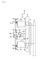
- FIG. 7 is a front view of a frame 80 A and the first unreeling failure detecting portion 130 .
- FIG. 8 is a view illustrating the schematic constitution of a second tension adjusting portion 210 , a second unreeling failure detecting portion 230 , and a second tension detecting portion 250 , each of which is provided for a helical winding device 40 .
- FIG. 9 is a perspective view of a tension device 200 .
- FIG. 10 is a side view of the tension device 200 .
- FIG. 11 is a simplified schematic view illustrating a mechanism that allows a fourth shaft 264 to swing.
- a filament winding device 100 (hereinafter referred to as “FW device 100 ”) according to the first embodiment of the present invention will be described.
- the FW device 100 is a device that winds a plurality of fiber bundles F, in which resin is impregnated, around the circumference of a liner 1 , by repeatedly alternating hoop winding by use of a hoop winding device 30 with helical winding by use of a helical winding device 40 with respect to the liner 1 .
- FIG. 1 illustrates a state where the hoop winding device 30 is disposed at a winding position.
- Arrows A and B illustrated in FIG. 1 represent the back-and-front direction of the FW device 100 and the transfer direction of the liner 1 regarding the helical winding.
- the liner 1 is reciprocated in the back-and-front direction of the FW device 100 , so that there is a case where the liner 1 is transferred in the direction of the arrow A, and there is a case where the liner 1 is transferred in the direction of the arrow B.
- the direction in which the liner 1 is transferred is defined as a front side, and the side opposite to the front side is defined as a back side.
- the liner 1 is reciprocated in the back-and-front direction, so that the front side and the back side are determined in accordance with the transfer direction of the liner 1 .
- the liner 1 is a hollow container formed of, for example, aluminum members having high intensity or polyamide resin and formed in an approximately cylindrical shape. Regarding the liner 1 , the plurality of fiber bundles F are wound around an outer circumferential surface 1 S, and a plurality of fiber layers are formed, thereby improving the performance of pressure resistance. That is, the liner 1 is of a base material constituting a pressure-resistant container. It is noted that, in the description below, the liner 1 means both a state before the fiber bundles F are wound and a state where the fiber bundles F are in the course of being wound. For example, the outer circumferential surface 1 S of the liner 1 may mean the surface of the fiber bundles F wound.
- the FW device 100 is mainly constituted by a main base 10 , a liner transfer device 20 , the hoop winding device 30 , the helical winding device 40 , a creel stand 50 , and a controller 90 .
- the main base 10 constitutes the base of the FW device 100 .
- a liner-transfer-device rail 11 is provided on the upper portion of the main base 10 .
- the liner transfer device 20 is placed on the liner-transfer-device rail 11 .
- a hoop-winding-device rail 12 is provided in parallel to the liner-transfer-device rail 11 on the upper portion of the main base 10 .
- the hoop winding device 30 is placed on the hoop-winding-device rail 12 .
- the liner transfer device 20 and the hoop winding device 30 can be transferred with respect to the main base 10 .
- the helical winding device 40 is fixed on the main base 10 .
- the liner transfer device 20 is a device that transfers the liner 1 while rotating the liner 1 .
- the liner transfer device 20 rotates the liner 1 about the back-and-front direction of the FW device 100 as a central axis and transfers the liner 1 in the back-and-front direction of the FW device 100 .
- the liner transfer device 20 is mainly constituted by a base 21 and a liner supporting portion 22 .
- the drive of the liner transfer device 20 is controlled by the controller 90 .
- a pair of liner supporting portions 22 are provided on the upper portion of the base 21 .
- the liner supporting portion 22 is constituted by a liner supporting frame 23 and a rotary shaft 24 .
- the liner supporting frame 23 is extended upward from the base 21 .
- the rotary shaft 24 is extended from the liner supporting frame 23 in the back-and-front direction.
- the liner 1 is mounted on the rotary shaft 24 and rotated in one direction by means of a power mechanism not illustrated.
- the liner transfer device 20 rotates the liner 1 about the back-and-front direction of the FW device 100 as the central axis and allows the liner 1 to be transferred in the back-and-front direction of the FW device 100 .
- the hoop winding device 30 is a device that simultaneously winds the plurality of fiber bundles F around the outer circumferential surface 1 S of the liner 1 and forms fiber layers.
- the hoop winding device 30 performs so-called hoop winding in which the winding angle of the fiber bundles F is positioned approximately vertical to the back-and-front direction of the FW device 100 .
- the hoop winding device 30 is mainly constituted by a base 31 , a power mechanism 32 , and a hoop wrapping device 33 .
- the drive of the hoop winding device 30 is controlled by the controller 90 .
- the hoop wrapping device 33 that is rotated by the power mechanism 32 is provided on the base 31 .
- the hoop wrapping device 33 includes a wrapping table 34 as a fiber bundle head.
- a space through which the liner 1 penetrates is provided in the center of the wrapping table 34 , and a plurality of bobbins (four in the present embodiment) BA, BB, BC, and BD are arranged in the periphery of the space (see FIG. 4 ).
- the respective fiber bundles F are supplied from the bobbins BA, BB, BC, and BD to the outer circumferential surface 1 S of the liner 1 .
- the power mechanism 32 rotates the hoop wrapping device 33 about the central axis of the liner 1 .
- the position of the liner 1 is fixed, and the hoop winding device 30 is reciprocated along the direction of the central axis of the liner 1 while the hoop wrapping device 33 is rotated about the central axis of the liner 1 .
- the hoop winding is performed in this manner.
- the hoop winding device 30 includes the wrapping table 34 as the fiber bundle head that allows the fiber bundles F supplied from the bobbins BA, BB, BC, and BD to face the outer circumferential surface 1 S of the liner 1 , and the hoop winding device 30 is configured to simultaneously wind the plurality of fiber bundles F on the liner 1 by relatively rotating the wrapping table 34 and the liner 1 , centering on the axis of the liner 1 .
- the hoop winding device 30 performs the hoop winding, in which the winding angle of the fiber bundles F is positioned approximately vertical to the back-and-front direction of the FW device 100 , to the outer circumferential surface 1 S of the liner 1 . It is noted that the winding form of the fiber bundles F is freely changed by adjusting the transfer speed of the hoop winding device 30 or the rotational speed of the wrapping table 34 .
- the helical winding device 40 is a device that simultaneously winds the plurality of fiber bundles F on the outer circumferential surface 1 S of the liner 1 and forms the fiber layers.
- the helical winding device 40 performs so-called helical winding in which the winding angle of the fiber bundles F corresponds to a predetermined value (for example, 0 to 60 degrees) with respect to the back-and-front direction of the FW device 100 .
- the helical winding device 40 is mainly constituted by a base 41 and a helical wrapping device 42 .
- the drive of the helical winding device 40 is controlled by the controller 90 .
- the helical wrapping device 42 is provided on the base 41 .
- the helical wrapping device 42 includes a first helical head 43 and a second helical head 44 .
- the plurality of fiber bundles F are supplied from a plurality of bobbins B 1 , B 2 , . . . B 180 (180 bobbins in the present invention) supported by the creel stand 50 to the first helical head 43 and the second helical head 44 , and the plurality of fiber bundles F are guided to the outer circumferential surface 1 S of the liner 1 .
- a plurality of nozzles (not illustrated) (each of 90 nozzles in the present invention) are radially provided in the first helical head 43 and the second helical head 44 with respect to the outer circumferential surface 1 S of the liner 1 .
- the plurality of fiber bundles F are guided by the plurality of nozzles to the outer circumferential surface 1 S of the liner 1 , and the helical winding is performed in concurrence with the passage and rotation of the liner 1 .
- the helical winding device 40 is fixed, and the liner 1 is transferred by the liner transfer device 20 in the rotary axial direction while being rotated. Accordingly, the helical winding is performed in this manner.
- the helical winding device 40 includes the first helical head 43 and the second helical head 44 as the fiber bundle head that allows the fiber bundles F supplied from the plurality of bobbins B 1 , B 2 , . . . and B 180 to face the outer circumferential surface 1 S of the liner 1 , and the helical winding device 40 is configured to simultaneously wind the plurality of fiber bundles F on the liner 1 by relatively rotating the first helical head 43 and the second helical head 44 , and the liner 1 , centering on the axis of the liner 1 .
- the helical winding device 40 performs the helical winding, in which the winding angle of the fiber bundles F corresponds to a predetermined value with respect to the back-and-front direction of the FW device 100 , on the outer circumferential surface 1 S of the liner 1 . It is noted that the winding form of the fiber bundles F is freely changed by adjusting the transfer speed or the rotational speed of the liner 1 .
- the creel stand 50 supplies the plurality of fiber bundles F ( 180 in the present invention) to the plurality of nozzles (each of 90 in the present invention) provided in the first helical head 43 and the second helical head 44 of the helical winding device 40 .
- the creel stand 50 is mainly constituted by a rack 51 , bobbin holder shafts 52 , and guides 53 .
- a plurality of bobbin holder shafts 52 are mounted in parallel to each other.
- the bobbins B 1 , B 2 , . . . and B 180 are supported on the bobbin holder shafts 52 in a freely rotatable manner.
- the bobbins B 1 , B 2 , . . . and B 180 are rotated by drawing out the fiber bundles F, thereby unreeling the fiber bundles F.
- a plurality of guides 53 that guide the fiber bundles F are provided on the paths of the fiber bundles F advancing from each of the bobbins B 1 , B 2 , . . . and B 180 to the liner 1 .
- the plurality of fiber bundles F unreeled from each of the bobbins B 1 , B 2 , . . . and B 180 are supplied to each nozzle of the corresponding helical winding device 40 via the plurality of guides 53 .
- the creel stand 50 can supply the plurality of fiber bundles F to the plurality of nozzles constituting the helical winding device 40 .
- the FW device 100 of the present embodiment includes a plurality of creel stands 50 , which is similar to the creel stand 50 illustrated in FIG. 2 , and is configured to supply the plurality of fiber bundles F from each creel stand 50 to the helical winding device 40 .
- a first tension adjusting portion 110 a first unreeling failure detecting portion 130 , and a first tension detecting portion 150 , each of which is provided in the hoop winding device 30 .
- the schematic constitution of these portions will be described referring to FIG. 3 .
- the first tension adjusting portion 110 , the first unreeling failure detecting portions 130 , and the first tension detecting portions 150 are arranged on the yarn paths leading from the plurality of bobbins BA, BB, BC, and BD to the liner 1 with regard to the wrapping table 34 .
- a unit of first tension adjusting portion 110 is provided for the plurality of fiber bundles F that are unreeled from the plurality of bobbins BA, BB, BC, and BD.
- the first tension adjusting portion 110 collectively adjusts the tension of the plurality of fiber bundles F.
- the first tension adjusting portion 110 is electrically connected to the controller 90 , and the drive of the first tension adjusting portion 110 is controlled by the controller 90 .
- the first tension detecting portions 150 are provided between the liner 1 and the first tension adjusting portion 110 .
- the first tension detecting portions 150 are individually arranged for the plurality of fiber bundles F.
- the first tension detecting portions 150 individually detect the tension of the plurality of fiber bundles F.
- the first tension detecting portions 150 detect the tension of each fiber bundle F and transmit a detection signal to the controller 90 .
- the controller 90 controls the drive of the first tension adjusting portion 110 based on the detection signal from the first tension detecting portions 150 .
- the first tension adjusting portion 110 collectively adjusts the tension of the plurality of fiber bundles F in accordance with the detection results of the first tension detecting portions 150 .
- the first unreeling failure detecting portions 130 individually detect the unreeling failure of the fiber bundles F on the plurality of bobbins BA, BB, BC, and BD for each of the bobbins BA, BB, BC, and BD.
- the first unreeling failure detecting portions 130 are provided on the yarn paths between the plurality of bobbins BA, BB, BC, and BD and the first tension adjusting portion 110 .
- bobbin supporting portions 50 are arranged at four places corresponding to the bobbins BA, BB, BC, and BD on the wrapping table 34 of the hoop winding device 30 .
- Frames 80 A, . . . and 80 D are provided in the vicinity of each bobbin supporting portion 50 .
- the constitution of the bobbin supporting portions 50 provided in accordance with the bobbins BA, BB, BC, and BD and the frames 80 A, . . . and 80 D is approximately the same.
- the frame 80 A will be mainly described.
- the wrapping table 34 is rotated by the power mechanism 32 in the direction of an arrow R in FIG. 4 .
- the power mechanism 32 is connected to the controller 90 , and the rotation and stoppage of the power mechanism 32 are controlled based on the signals from the controller 90 .
- the fiber bundles F guided from a fiber supply guide 75 to the liner 1 are rotated in the direction of the arrow R while being wound around the outer circumferential surface 1 S of the liner 1 .
- the fiber bundles F are supplied in the direction of an arrow FA by the rotation of the wrapping table 34 .
- the bobbin supporting portion 50 that supports the bobbin BA is supported in a freely rotatable manner with respect to the wrapping table 34 and coupled with a hysteresis brake 51 as a braking portion.
- the hysteresis brake 51 brakes the rotation of the bobbin BA supported by the bobbin supporting portion 50 .
- the fiber bundle F is pulled in a state where the bobbin BA is supported by the bobbin supporting portion 50 , whereby the bobbin BA is rotated, and the fiber bundle F is drawn out.
- the frames 80 A, . . . and 80 D respectively support guide rollers 71 ( 71 A, 71 B, and 71 C) . . . and 74 ( 74 A, 74 B, and 74 C).
- Four fiber bundles F from the bobbins BA, BB, BC, and BD supported by the bobbin supporting portions 50 are guided by the guide rollers 71 ( 71 B, and 71 C) . . . and 74 ( 74 A, 74 B, and 74 C) and consolidated by the guide roller 74 C and guided to the fiber supply guide 75 via the guide roller 71 A.
- the fiber supply guide 75 supplies the four fiber bundles F consolidated to the outer circumferential surface 1 S of the liner 1 .
- the first tension adjusting portion 110 is provided in such a manner as to be interposed on the path of the fiber bundle F, leading from the guide roller 71 A to the fiber supply guide 75 .
- the first tension detecting portion 150 is provided in such a manner as to be interposed on the path of the fiber bundle F, leading from the first tension adjusting portion 110 to the fiber supply guide 75 .
- the first tension adjusting portion 110 collectively adjusts the tension of the four fiber bundles F consolidated.
- the first tension adjusting portion 110 includes a frame 111 that serves as a base.
- a first shaft 112 , a second shaft 113 , and a third shaft 114 are provided in the frame 111 .
- the fiber bundle F is wound around in order of the first shaft 112 , the second shaft 113 , and the third shaft 114 .
- the first shaft 112 is a roller that receives the fiber bundle F guided from the side of the guide roller 71 A.
- the third shaft 114 is a roller that forwards the fiber bundle F to the side of the fiber supply guide 75 .
- the first shaft 112 and the third shaft 114 are supported by the frame 111 .
- the second shaft 113 is supported by one end portion of an arm 115 .
- the other end portion of the arm 115 is provided on the frame 111 in such a manner as to be swingable in the direction of D 11 and in the direction of D 12 , centering on a supporting shaft 116 .
- the direction of D 11 is the direction in which the second shaft 113 is separated away from the first shaft 112 and the third shaft 114 .
- the direction of D 12 is the direction in which the second shaft 113 comes close to the first shaft 112 and the third shaft 114 .
- the arm 115 swings, which changes the paths of the fiber bundles F leading from the first shaft 112 to the third shaft 114 , and the frictional force applied to the fiber bundles F is changed, thereby adjusting the tension of the fiber bundles F.
- the tension applied to the fiber bundles F increases.
- the tension applied to the fiber bundles F decreases.
- a worm wheel 118 constituting a worm gear 117 is fixed on the supporting shaft 116 .
- the worm wheel 118 is fixed on the supporting shaft 116 and integrated with the arm 115 in a freely rotatable manner.
- a worm 124 constituting the worm gear 117 is fixed on one end portion of the shaft 123 .
- the worm gear 117 is constituted by engaging the worm 124 with the worm wheel 118 .
- a first motor M 1 is provided in the frame 111 .
- a servomotor is used as the first motor M 1 .
- a first bevel gear 125 is fixed on the driving shaft of the first motor M 1 .
- a second bevel gear 126 engaged with the first bevel gear 125 is fixed on the other end portion of the shaft 123 .
- the first motor M 1 is electrically connected to the controller 90 , and the drive of the first motor M 1 is controlled by the controller 90 .
- the rotation angle of the first motor M 1 is controlled by the controller 90 , thereby changing the swing angle in the direction of D 11 or in the direction of D 12 of the arm 115 and adjusting the tension of the fiber bundles F.
- the tension of the fiber bundles F acts upon the second shaft 113 , which causes the arm 115 to receive the rotating force in the direction of D 12 .
- This force is transmitted from the worm wheel 118 to the worm 124 .
- the worm gear 117 is provided between the first motor M 1 and the arm 115 , which makes it unnecessary to separately provide the whirl-stop mechanism of the arm 115 .
- the rotation force from the arm 115 is not transmitted as a force that reverses the driving shaft of the first motor M 1 , so that a relatively small-size motor can be used as the first motor M 1 .
- the first tension detecting portions 150 are individually arranged for the plurality of fiber bundles F and individually detect the tension of each fiber bundle F.
- the first tension detecting portions 150 detect the tension of each fiber bundle F and transmit the detection signal to the controller 90 .
- the controller 90 controls the drive of the first tension adjusting portion 110 based on the detection signal from the first tension detecting portions 150 .
- the first tension detecting portions 150 transmit a detection signal to the effect that the tension is lower than the predetermined value, to the controller 90 .
- the controller 90 controls the rotation angle of the first motor M 1 based on the detection signal from the first tension detecting portions 150 in such a manner that the second shaft 113 provided in the arm 115 is transferred in the direction of D 11 , and that the tension of fiber bundles F increases.
- the first tension detecting portions 150 transmit a detection signal to the effect that the tension is higher than the predetermined value, to the controller 90 .
- the controller 90 controls the rotation angle of the first motor M 1 based on the detection signal from the first tension detecting portions 150 in such a manner that the second shaft 113 provided in the arm 115 is transferred in the direction of D 12 , and that the tension of fiber bundles F decreases.
- the first tension adjusting portion 110 can collectively adjust the tension of the plurality of fiber bundles F in accordance with the detection result of the first tension detecting portions 150 .
- the respective first unreeling failure detecting portions 130 are provided in the frames 80 A, 80 B, 80 C, and 80 D.
- the respective first unreeling failure detecting portions 130 provided in the frames 80 A, 80 B, 80 C, and 80 D are provided in such a manner as to be interposed on the paths of the fiber bundles F leading from the bobbins BA, BB, BC, and BD to first guide rollers 71 B, 72 B, 73 B, and 74 B.
- the respective first unreeling failure detecting portions 130 corresponding to the bobbins BA, BB, BC, and BD have approximately the same constitution, and hereinafter, the first unreeling failure detecting portion 130 corresponding to the bobbin BA will be mainly described.
- the first unreeling failure detecting portion 130 includes a second roller 62 .
- a first roller 61 , a third roller 63 , and a fourth roller 64 , other than the second roller 62 , are provided in the frame 80 A.
- the fiber bundle F is wound around in order of the first roller 61 , the second roller 62 , the third roller 63 , and the fourth roller 64 .
- the first roller 61 is a roller that serves as a fulcrum of the fiber bundle F unreeled from the bobbin BA.
- the fourth roller 64 is a roller that guides the fiber bundle F to the guide roller 71 B.
- the third roller 63 is supported by the arm 69 and constitutes a take-up portion 60 for the fiber bundle F.
- the first roller 61 and the fourth roller 64 are supported by the frame 80 A.
- the arm 69 constituting the take-up portion 60 is supported in such a manner as to be swingable in the directions of D 3 and D 4 and biased by a torsional spring not illustrated in the direction of D 4 .
- the arm 69 rotates to a position, at which the arm 69 is abutted with the supporting portion of the first roller 61 , and is on standby.
- the tension of the fiber bundle F is less than the set value, which causes looseness, the arm 69 rotates in the direction of D 4 by means of biased force of the torsional spring and absorbs the looseness generated in the fiber bundle F.
- the second roller 62 constituting the first unreeling failure detecting portion 130 is supported by one end portion of an arm 65 .
- the other end portion of the arm 65 is provided on the frame 80 A in such a manner as to be swingable in the directions D 21 and D 22 , centering on a supporting shaft 66 .
- the direction D 21 is the direction in which the second roller 62 is separated away from the fourth roller 64 .
- the direction D 22 is the direction in which the second roller 62 comes close to the fourth roller 64 . That is, the arm 65 swings, thereby increasing and decreasing the length of the path of the fiber bundle F between the second roller 62 and the fourth roller 64 .
- the supporting shaft 66 penetrates the frame 80 A up to the back surface side (the back side of the page), and the second roller 62 is biased by the torsional spring (not illustrated) provided in the supporting shaft 66 in the direction (the direction of D 21 ) in which the second roller 62 is separated away from the fourth roller 64 . It is noted that an imaginary plane on which the arm 65 swings is provided in parallel to the rotary shaft of the wrapping table 34 . Accordingly, the influence of the centrifugal force on the arm 65 , which is attributed to the rotation of the wrapping table 34 , is minimized.
- a first detection piece 67 is fixed on the supporting shaft 66 that supports the arm 65 on the back surface side (the back side of the page) of the frame 80 A.
- the first detection piece 67 swings in response to the swing of the arm 65 .
- a first detection portion 68 is provided on the back surface side (the back side of the page) of the frame 80 A.
- the second roller 62 is biased by the biased force of the torsional spring provided in the supporting shaft 66 of the arm 65 , and the arm 65 is rotated in the direction of D 21 and rotated in the direction in which the arm 65 is separated away from the fourth roller 64 (standby position).
- the second roller 62 When the tension applied to the fiber bundle F is increased, compared with the predetermined tension, that is, when there occurs abnormality in unreeling the fiber bundle F on the bobbin BA, the second roller 62 is pressed against the biased force of the torsional spring provided in the supporting shaft 66 of the arm 65 , and the arm 65 is rotated in the direction of D 22 and rotated in the direction in which the arm 65 comes close to the fourth roller 64 (detection position).
- the first detection portion 68 detects the first detection piece 67 in a state where the arm 65 rotates to the detection position, thereby detecting that the arm 65 is rotated to a predetermined position. Also, the first detection portion 68 does not detect the first detection piece 67 in a state where the arm 65 does not rotate to the detection position, thereby detecting that the arm 65 is not rotated to the predetermined position. That is, the first detection portion 68 detects that the unreeling of the fiber bundle F on the bobbin BA is normal, and the predetermined tension is applied to the fiber bundle F, and detects that the failure occurs in unreeling the fiber bundle F on the bobbin BA, and the tension applied to the fiber bundle F is being increased.
- the first detection portion 68 When the first detection portion 68 detects that the failure occurs in unreeling the fiber bundle F on the bobbin BA, the first detection portion 68 transmits the detection signal to the effect that the failure occurs, to the controller 90 . Also, when the first detection portion 68 detects that the unreeling of the fiber bundle F on the bobbin BA is normal, the first detection portion 68 transmits the detection signal to the effect that the unreeling is normal, to the controller 90 .
- known sensors such as a photoelectric sensor can be used. Electric power required for the first detection portion 68 may be supplied from outside of the wrapping table 34 , or a battery may be mounted on the wrapping table 34 , and the electric power is supplied from the battery.
- the controller 90 When the first detection portion 68 detects that the failure occurs in unreeling the fiber bundle F on the bobbin BA, the controller 90 generates an alarm sound or the like by means of a notification portion not illustrated, based on the detection signal from the first detection portion 68 . It is noted that there is a case where, even when the failure does not occur in unreeling the fiber bundle F on the bobbin BA, the tension applied to the fiber bundle F is temporarily increased due to an increase in the winding velocity V 1 of the fiber bundle F immediately after the hoop winding device 30 starts winding the fiber bundle F. In this case, it is not necessary to exert the alarm sound or the like.
- the controller 90 does not exert the alarm sound or the like when a duration time of an abnormality detection signal from the first detection portion 68 is equal to or less than a set time. Also, even when the duration time of the abnormality detection signal from the first detection portion 68 is equal to or less than a set time, but when the abnormality detection signals are received at a predetermined frequency or higher, the controller 90 determines that some abnormality occurs and exerts the alarm sound or the like.
- the above-mentioned FW device 100 according to the present embodiment has the following advantageous effects.
- the FW device 100 includes the first tension adjusting portion 110 that collectively adjusts the tension of the plurality of fiber bundles F unreeled from the plurality of bobbins BA, BB, BC, and BD and the first unreeling failure detecting portions 130 that individually detect the unreeling failure for each of the bobbins BA, BB, BC, and BD. Accordingly, the first tension adjusting portion 110 and the first unreeling failure detecting portions 130 are miniaturized, and the cost of the first tension adjusting portion 110 and the first unreeling failure detecting portions 130 can be reduced, and the first tension adjusting portion 110 and the first unreeling failure detecting portions 130 can be easily arranged. Also, the first tension adjusting portion 110 can collectively adjust the tension of the plurality of fiber bundles F, so that the control of the tension of the plurality of fiber bundles F can be easily made.
- the first unreeling failure detecting portions 130 of the FW device 100 are provided on the yarn paths between the first tension adjusting portion 110 and the plurality of bobbins BA, BB, BC, and BD.
- the variation of the tension of the fiber bundles F, which is detected by the first unreeling failure detecting portions 130 is attributed to the unreeling failure on the bobbins BA, BB, BC, and BD, and the variation of the tension due to the operational failure of the first tension adjusting portion 110 and the like is not included.
- the variation of the low tension due to the unreeling failure on the bobbins BA, BB, BC, and BD can be detected, and the unreeling failure on the bobbins BA, BB, BC, and BD can be detected with high accuracy.
- the first tension detecting portions 150 that detect the tension of the plurality of fiber bundles F are provided between the liner 1 and the first tension adjusting portion 110 , and the first tension adjusting portion 110 collectively adjusts the tension of the plurality of fiber bundles F in accordance with the detection results of the first tension detecting portions 150 . Accordingly, the control of the tension of the plurality of fiber bundles F can be easily made.
- the fiber bundle head in the hoop winding device 30 of the FW device 100 is the wrapping table 34 rotatably installed around the outer circumference of the liner 1 , and the wrapping table 34 rotates about the axis of the liner 1 and transfers in the axial direction, thereby simultaneously winding the plurality of fiber bundles F supplied from the bobbins BA, BB, BC, and BD on the liner 1 . Accordingly, the first tension adjusting portion 110 and the first unreeling failure detecting portions 130 can be easily arranged in the wrapping table 34 of the hoop winding device 30 .
- the first unreeling failure detecting portions 130 of the FW device 100 are individually provided for the plurality of bobbins BA, BB, BC, and BD and include the first detection piece 67 that changes from the standby position to the detection position, upon reception of the tension of the fiber bundles F unreeled, and the first detection portion 68 that detects that the first detection piece 67 is positioned at the detection position. Accordingly, the first unreeling failure detecting portions 130 can be constituted based on simple constitution, and the unreeling failure on the bobbins BA, BB, BC, and BD can be detected with high accuracy.
- the first detection piece 67 of the first unreeling failure detecting portions 130 of the FW device 100 is biased by the torsional spring and positioned at the standby position. Accordingly, with simple constitution, the unreeling failure on the bobbins BA, BB, BC, and BD can be detected with high accuracy.
- the first detection portions 68 of the first unreeling failure detecting portions 130 of the FW device 100 are the photoelectric sensors that are individually provided corresponding to the first detection pieces 67 . Accordingly, it is possible to steadily determine on which bobbin, out of the bobbins BA, BB, BC, and BD, the unreeling failure occurs or whether or not the unreeling failure occurs.
- a second tension adjusting portion 210 a second unreeling failure detecting portion 230 , and a second tension detecting portion 250 are provided for the helical winding device 40 .
- the schematic constitution of these portions will be described.
- the second tension adjusting portion 210 , the second unreeling failure detecting portions 230 , and the second tension detecting portions 250 are arranged on the yarn paths leading from the plurality of bobbins B 1 , B 2 , . . . to the first helical head 43 and the second helical head 44 .
- 180 bobbins B 1 , B 2 , . . . and B 180 are divided into 15 bobbin groups G 1 , G 2 , and G 15 , and each of the bobbin groups G 1 , G 2 , . . . and G 15 has 12 bobbins B 1 , B 2 , . . .
- the second tension adjusting portion 210 for which the second tension adjusting portion 210 , the second unreeling failure detecting portions 230 , and the second tension detecting portions 250 are provided.
- the bobbin group G 1 made up of 12 bobbins B 1 , B 2 , . . . and B 12 is exemplified.
- the second tension adjusting portion 210 and the second unreeling failure detecting portions 230 are constituted as one unit of tension device 200 .
- the second tension adjusting portion 210 is provided for common use with respect to the plurality of fiber bundles F unreeled from the plurality of bobbins B 1 , B 2 , . . . and B 12 .
- the second tension adjusting portion 210 collectively adjusts the tension of the plurality of fiber bundles F.
- the second tension adjusting portion 210 is electrically connected to the controller 90 , and the drive of the second tension adjusting portion 210 is controlled by the controller 90 .
- the second tension detecting portions 250 are provided between the first helical head 43 and the second helical head 44 and the second tension adjusting portion 210 .
- the second tension detecting portions 250 are individually provided for the plurality of fiber bundles F.
- the second tension detecting portions 250 individually detect the tension of the plurality of fiber bundles F.
- the second tension detecting portions 250 detect the tension of each fiber bundle F and transmit the detection signal to the controller 90 .
- the controller 90 controls the drive of the second tension adjusting portion 210 based on the detection signal from the second tension detecting portions 250 .
- the second tension adjusting portion 210 collectively adjusts the tension of the plurality of fiber bundles F in accordance with the detection results of the second tension detecting portions 250 .
- the second unreeling failure detecting portions 230 individually detect the unreeling failure of the fiber bundles F on the plurality of bobbins B 1 , B 2 , . . . and B 12 for each of the bobbins B 1 , B 2 , . . . and B 12 .
- the second unreeling failure detecting portions 230 are provided on the yarn paths between the plurality of bobbins B 1 , B 2 , . . . and B 12 and the second tension adjusting portion 210 .
- the second tension adjusting portion 210 and the second unreeling failure detecting portions 230 are constituted as one unit of tension device 200 .
- the position at which the tension device 200 is arranged may be placed on the creel stand 50 as illustrated in FIG. 8 , but not limited to this.
- 15 units of tension devices 200 are provided in accordance with the 15 bobbin groups G 1 , G 2 , . . . and G 15 . Fifteen units of tension devices 200 have the same constitution.
- the tension device 200 is provided in such a manner as to be interposed on the paths of the fiber bundles F leading from the plurality of bobbins B 1 , B 2 , . . . and B 12 to the first helical head 43 and the second helical head 44 .
- the tension device 200 includes a first frame 211 that serves as a base. Twelve sets of second frames 212 and third frames 213 are arranged side by side on the first frame 211 in accordance with the fiber bundles F from the 12 bobbins B 1 , B 2 , . . . and B 12 .
- the respective first supporting portions 214 are provided for the second frames 212 .
- a first roller 261 is provided at the one end of each second frame 212 , and a third roller 263 is provided at approximately the central position of each second frame 212 .
- the first roller 261 is a roller constituting the second unreeling failure detecting portion 230 .
- the third roller 263 is a roller that is common to the second tension adjusting portion 210 and the second unreeling failure detecting portion 230 .
- a first notch portion 221 is formed between the first roller 261 and the third roller 263 .
- the first notch portion 221 is a notch portion that secures space in which a second roller 262 constituting the second unreeling failure detecting portion 230 swings.
- a second notch portion 222 is formed on the opposite side to the first notch portion 221 with respect to the third roller 263 .
- the second notch portion 222 is a notch portion that secures space in which a fourth shaft 264 constituting the second tension adjusting portion 210 swings.
- the first notch portion 221 and the second notch portion 222 of each second frame 212 are provided as a contiguous space in the direction in which the 12 second frames 212 are traversed.
- the second tension adjusting portion 210 collectively adjusts the tension of 12 fiber bundles F unreeled from the plurality of bobbins B 1 , B 2 , . . . and B 12 .
- the second tension adjusting portion 210 includes the third rollers 263 , the fourth shaft 264 , a fifth shaft 265 , and sixth rollers 266 .
- the fiber bundles F are wound around in order of the third rollers 263 , the fourth shaft 264 , the fifth shaft 265 , and the sixth rollers 266 .
- the third rollers 263 are rollers that receive the fiber bundles F guided from the side of the plurality of bobbins B 1 , B 2 , . . .
- the sixth rollers 266 are rollers that forward the fiber bundles F to the side of the first helical head 43 or the side of the second helical head 44 .
- the sixth rollers 266 are supported by the third frames 213 .
- the fifth shaft 265 is supported by the first supporting portions 214 .
- the fixation of the first supporting portions 214 on the second frames 212 is carried out by elongated holes 215 and bolts 216 formed on the second frames 212 .
- the fixed positions with the bolts 216 are changed, thereby changing the positions of the first supporting portions 214 with respect to the second frames 212 . Accordingly, the position of the fifth shaft 265 is adjusted, thereby adjusting the tension of the fiber bundles F.
- the fourth shaft 264 is one member corresponding to the 12 fiber bundles F and arranged in such a manner as to penetrate a space formed by the second notch portions 222 of 12 second frames 212 . As illustrated in FIG. 9 , the both end portions of the fourth shaft 264 are supported by one end portions of two arms 217 . The other end portions of the two awls 217 are connected to a supporting shaft 218 . The both end portions of the supporting shaft 218 are swingably supported by second supporting portions 219 erected on the both sides of the first frame 211 . Accordingly, the fourth shaft 264 is provided in such a manner as to be swingable in the direction of D 31 and the direction of D 32 , centering on the supporting shaft 218 (see FIG. 10 ).
- the direction of D 31 is the direction in which the fourth shaft 264 is separated away from the third roller 263 and the fifth shaft 265 .
- the direction of D 32 is the direction in which the fourth shaft 264 comes close to the third roller 263 and the fifth shaft 265 .
- the swing of the fourth shaft 264 changes the paths of the fiber bundles F leading from the third rollers 263 to the fifth shaft 265 , which changes the frictional force acted on the fiber bundles F, so that the tension of the fiber bundles F can be adjusted.
- the fourth shaft 264 transfers in the direction of D 31 , the tension applied to the fiber bundles F increases.
- the fourth shaft 264 transfers in the direction of D 32 the tension applied to the fiber bundles F decreases.
- a worm wheel 228 constituting a worm gear 227 is fixed in the periphery of one end portion of the supporting shaft 218 .
- the worm wheel 228 , the arm 217 , the supporting shaft 218 and the fourth shaft 264 can be rotated as a unit.
- a second motor M 2 is provided above the worm wheel 228 .
- a servomotor is used as the second motor M 2 .
- a worm 229 constituting the worm gear 227 is fixed on the driving shaft of the second motor M 2 .
- the worm gear 227 is constituted by engaging the worm 229 with the worm wheel 228 .
- the second motor M 2 is electrically connected to the controller 90 , and the drive of the second motor M 2 is controlled by the controller 90 .
- the rotation angle of the second motor M 2 is controlled by the controller 90 , thereby changing the swing angle in the direction of D 31 or in the direction of D 32 of the arm 217 and the fourth shaft 264 and adjusting the tension of the fiber bundles F.
- the tension of the fiber bundles F acts upon the fourth shaft 264 , which causes the arm 217 and the fourth shaft 264 to receive the rotating force in the direction of D 32 (see FIG. 10 ).
- This force is transmitted from the worm wheel 228 to the worm 229 .
- the worm gear 227 is provided between the second motor M 2 and the fourth shaft 264 , which makes it unnecessary to separately provide the whirl-stop mechanism of the arm 217 and the fourth shaft 264 .
- the rotation force from the arm 217 is not transmitted as a force that reverses the driving shaft of the second motor M 2 , so that a relatively small-size motor can be used as the second motor M 2 .
- the second tension detecting portions 250 are individually arranged for the plurality of fiber bundles F and individually detect the tension of each fiber bundle F.
- the second tension detecting portions 250 are provided in such a manner as to be interposed on the paths of the fiber bundles F leading from the second tension adjusting portion 210 of the tension device 200 to the first helical head 43 or the second helical head 44 .
- the second tension detecting portions 250 detect the tension of each fiber bundle F and transmit the detection signal to the controller 90 .
- the controller 90 controls the drive of the second tension adjusting portion 210 based on the detection signal from the second tension detecting portions 250 .
- the second tension detecting portion 250 transmits a detection signal to the effect that the tension is lower than the predetermined value to the controller 90 .
- the controller 90 controls the rotation angle of the second motor M 2 based on the detection signal from the second tension detecting portion 250 in such a manner that the fourth shaft 264 provided in the arm 217 is transferred in the direction of D 31 , and that the tension of fiber bundles F increases.
- the second tension detecting portion 250 transmits a detection signal to the effect that the tension is higher than the predetermined value, to the controller 90 .
- the controller 90 controls the rotation angle of the second motor M 2 based on the detection signal from the second tension detecting portion 250 in such a manner that the fourth shaft 264 provided in the arm 217 is transferred in the direction of D 32 , and that the tension of fiber bundles F decreases.
- the second tension adjusting portion 210 can collectively adjust the tension of the plurality of fiber bundles F in accordance with the detection results of the second tension detecting portions 250 .
- the respective second unreeling failure detecting portions 230 constituting the tension device 200 are provided for the 12 second frames 212 .
- the respective second unreeling failure detecting portions 230 are provided at positions interposed on the paths of the fiber bundles F leading from the bobbins B 1 , B 2 , . . . and B 12 to the second tension adjusting portion 210 .
- the second unreeling failure detecting portions 230 corresponding to the bobbins B 1 , B 2 , . . . and B 12 have approximately the same constitution, and hereinafter, the second unreeling failure detecting portion 230 corresponding to the bobbin B 1 will be mainly described.
- the second unreeling failure detecting portion 230 includes a first roller 261 , a second roller 262 , and a third roller 263 .
- the fiber bundle F is wound round in order of the first roller 261 , the second roller 262 , and the third roller 263 .
- the first roller 261 is a roller that receives the fiber bundle F unreeled from the bobbin B 1 .
- the third roller 263 is a roller that is common to the second tension adjusting portion 210 .
- the second roller 262 is supported by an arm 231 .
- the arm 231 is bent in an approximately U shape, and the second roller 262 is supported in the periphery of the bent portion.
- One end portion of the arm 231 is provided in the second frame 212 in such a manner as to be swingable in the direction of D 41 and in the direction of D 42 , centering on a supporting shaft 232 .
- the direction of D 41 is the direction in which the second roller 262 is separated away from the first roller 261 and the third roller 263 .
- the direction of D 42 is the direction in which the second roller 262 comes close to the first roller 261 and the third roller 263 . That is, the arm 231 swings, thereby increasing and decreasing the length of the path of the fiber bundle F between the first roller 261 and the third roller 263 .
- the arm 231 is biased by a torsional spring 233 provided in the supporting shaft 232 in the direction (the direction of D 41 ) in which the second roller 262 is separated away from the first roller 261 and the third roller 263 . It is noted that a plurality of holes 234 for fixing the end portion of the torsional spring 233 are provided in the second frame 212 . The biased force of the arm 231 can be adjusted by changing the positions of the holes 234 for fixing the end portion of the torsional spring 233 .
- the other end portion of the arm 231 serves as a second detection piece 235 .
- the second detection piece 235 swings in response to the swing of the arm 231 .
- a second detection portion 238 is provided in the vicinity of the arm 231 .
- the second roller 262 When the predetermined tension is applied to the fiber bundle F, that is, when the unreeling of the fiber bundle F on the bobbin B 1 is normal, the second roller 262 is biased by the biased force of the torsional spring 233 provided in the supporting shaft 232 of the arm 231 , and the arm 231 is rotated in the direction of D 41 and rotated in the direction in which the arm 231 is rotated is separated away from the first roller 261 and the third roller 263 .
- the second roller 262 When the tension applied to the fiber bundle F is increased, compared with the predetermined tension, that is, when there occurs abnormality in unreeling the fiber bundle F on the bobbin B 1 , the second roller 262 is pressed against the biased force of the torsional spring 233 provided in the supporting shaft 232 of the arm 231 , and the arm 231 is rotated in the direction of D 42 , and rotated in the direction in which the arm 231 comes close to the first roller 261 and the third roller 263 .
- the second detection portion 238 detects the second detection piece 235 , thereby detecting that the arm 231 is rotated to a predetermined position. Also, when the second detection portion 238 does not detect the second detection piece 235 , the second detection portion 238 detects that the arm 231 is not rotated to the predetermined position. That is, the second detection portion 238 detects that the unreeling of the fiber bundle F on the bobbin B 1 is normal, and the predetermined tension is applied to the fiber bundle F, and detects that the failure occurs in unreeling the fiber bundle F on the bobbin B 1 , and the tension applied to the fiber bundle F is being increased.
- the second detection portion 238 When the second detection portion 238 detects that the failure occurs in unreeling the fiber bundle F on the bobbin B 1 , the second detection portion 238 transmits the detection signal to the effect that the failure occurs, to the controller 90 . Also, when the second detection portion 238 detects that the unreeling of the fiber bundle F on the bobbin B 1 is normal, the second detection portion 238 transmits the detection signal to the effect that the unreeling is normal, to the controller 90 . As the second detection portion 238 , known sensors such as a photoelectric sensor can be used.
- the controller 90 When the second detection portion 238 detects that the failure occurs in unreeling the fiber bundle F on the bobbin B 1 , the controller 90 generates an alarm sound or the like by means of a notification portion not illustrated, based on the detection signal from the second detection portion 238 . It is noted that there is a case where, even when the failure does not occur in unreeling the fiber bundle F on the bobbin B 1 , the tension applied to the fiber bundle F is temporarily increased due to an increase in the winding velocity of the fiber bundle F immediately after the helical winding device 40 starts winding the fiber bundle F. In this case, it is not necessary to exert the alarm sound or the like.
- the controller 90 does not exert the alarm sound or the like when a duration time of an abnormality detection signal from the second detection portion 238 is equal to or less than a set time. Also, even when the duration time of the abnormality detection signal from the second detection portion 238 is equal to or less than a set time, but when the abnormality detection signals are received at a predetermined frequency or higher, the controller 90 determines that some abnormality occurs and exerts the alarm sound or the like.
- the above-mentioned second detection portions 238 are each provided for 12 sets of second unreeling failure detecting portions 230 , but not limited to this.
- one second detection portion 238 may be installed in the direction in which the 12 second frames 212 are traversed. In this case, when the second detection piece 235 of any second unreeling failure detecting portion 230 , out of 12 sets of second unreeling failure detecting portions 230 , is detected, the occurrence of the unreeling failure on any of the bobbins B 1 , B 2 , . . . and B 12 can be detected.
- the photoelectric sensor when used as the second detection portion 238 , it cannot be determined what second detection piece 235 is detected based on what second unreeling failure detecting portion 230 , which makes it impossible to specify a bobbin on which the unreeling failure occurs. Accordingly, in place of the photoelectric sensor as the second detection portion 238 , a laser distance sensor that can measure a distance to a light-shielding position can be used as the second detection portion 238 . In this case, positional information on the second detection piece 235 detected can be obtained, and the second detection piece 235 detected can be specified, so that the bobbin on which the unreeling failure occurs can be specified.
- the FW device 100 includes the second tension adjusting portion 210 that collectively adjusts the tension of the plurality of fiber bundles F unreeled from the plurality of bobbins B 1 , B 2 , . . . and B 12 and the second unreeling failure detecting portions 230 that individually detect the unreeling failure for each of the bobbins B 1 , B 2 , . . . and B 12 .
- the second tension adjusting portion 210 and the second unreeling failure detecting portions 230 are miniaturized, and the cost of the second tension adjusting portion 210 and the second unreeling failure detecting portions 230 can be reduced, and the second tension adjusting portion 210 and the second unreeling failure detecting portions 230 can be easily arranged. Also, the second tension adjusting portion 210 can collectively adjust the tension of the plurality of fiber bundles F, so that the control of the tension of the plurality of fiber bundles F can be easily made.
- the second unreeling failure detecting portions 230 are provided on the yarn paths between the second tension adjusting portion 210 and the plurality of bobbins B 1 , B 2 , . . . .
- the variation of the tension of the fiber bundles F, which is detected by the second unreeling failure detecting portions 230 is attributed to the unreeling failure on the bobbins B 1 , B 2 , . . . , and the variation of the tension due to the operational failure of the second tension adjusting portion. 210 and the like is not included. Accordingly, the variation of the low tension due to the unreeling failure on the bobbins B 1 , B 2 , . . . can be detected, and the unreeling failure on the bobbins B 1 , B 2 , . . . can be detected with high accuracy.
- the second tension detecting portions 250 that detect the tension of the plurality of fiber bundles F are provided between the liner 1 and the second tension adjusting portion 210 , and the second tension adjusting portion 210 collectively adjusts the tension of the plurality of fiber bundles F in accordance with the detection results of the second tension detecting portions 250 . Accordingly, the control of the tension of the plurality of fiber bundles F can be easily made.
- the fiber bundle head is the first helical head 43 and the second helical head 44 that are installed around the outer circumference of the liner 1 , and the liner 1 transfers in the axial direction while rotating about the axis thereof, thereby simultaneously winding the plurality of fiber bundles F supplied from the bobbins B 1 , B 2 , . . . on the liner 1 .
- the second tension adjusting portion 210 and the second unreeling failure detecting portions 230 can be easily arranged in the FW device 100 that includes the first helical head 43 and the second helical head 44 of the helical winding device 40 .
- the second unreeling failure detecting portions 230 are individually provided for the plurality of bobbins B 1 , B 2 , . . . and include the second detection piece 235 that changes from the standby position to the detection position, upon reception of the tension of the fiber bundles F unreeled, and the second detection portion 238 that detects that the second detection piece 235 is positioned at the detection position. Accordingly, the second unreeling failure detecting portions 230 can be constituted based on simple constitution, and the unreeling failure on the bobbins B 1 , B 2 , . . . can be detected with high accuracy.
- the second detection piece 235 of the second unreeling failure detecting portion 230 is biased by the torsional spring 233 and positioned at the standby position. Accordingly, with simple constitution, the unreeling failure on the bobbins B 1 , B 2 , . . . can be detected with high accuracy.
- the filament winding device of the present invention can miniaturize the tension adjusting portion and the unreeling failure detecting portion, reduce the cost of the tension adjusting portion and the unreeling failure detecting portion, and arrange the tension adjusting portion and the unreeling failure detecting portion in an easy manner, which is industrially useful.
Landscapes
- Engineering & Computer Science (AREA)
- Mechanical Engineering (AREA)
- Textile Engineering (AREA)
- Quality & Reliability (AREA)
- Moulding By Coating Moulds (AREA)
- Filamentary Materials, Packages, And Safety Devices Therefor (AREA)
Applications Claiming Priority (3)
| Application Number | Priority Date | Filing Date | Title |
|---|---|---|---|
| JP2012-229341 | 2012-10-16 | ||
| JP2012229341A JP5698722B2 (ja) | 2012-10-16 | 2012-10-16 | フィラメントワインディング装置 |
| PCT/JP2013/078004 WO2014061673A1 (ja) | 2012-10-16 | 2013-10-15 | フィラメントワインディング装置 |
Publications (2)
| Publication Number | Publication Date |
|---|---|
| US20150266232A1 US20150266232A1 (en) | 2015-09-24 |
| US9796128B2 true US9796128B2 (en) | 2017-10-24 |
Family
ID=50488234
Family Applications (1)
| Application Number | Title | Priority Date | Filing Date |
|---|---|---|---|
| US14/436,061 Active 2034-06-27 US9796128B2 (en) | 2012-10-16 | 2013-10-15 | Filament winding device |
Country Status (5)
| Country | Link |
|---|---|
| US (1) | US9796128B2 (de) |
| JP (1) | JP5698722B2 (de) |
| CN (1) | CN104684712B (de) |
| DE (1) | DE112013005827B4 (de) |
| WO (1) | WO2014061673A1 (de) |
Families Citing this family (18)
| Publication number | Priority date | Publication date | Assignee | Title |
|---|---|---|---|---|
| CN106217838B (zh) * | 2016-08-01 | 2018-06-08 | 北京航空航天大学 | 碳纤维缠绕张力模块化控制系统及控制方法 |
| JP6881138B2 (ja) * | 2017-08-07 | 2021-06-02 | 村田機械株式会社 | フィラメントワインディング装置 |
| CN107604642A (zh) * | 2017-09-11 | 2018-01-19 | 浙江中新毛纺织有限公司 | 一种羊毛鳞片处理方法及处理设备 |
| JP6834900B2 (ja) * | 2017-10-20 | 2021-02-24 | トヨタ自動車株式会社 | 高圧タンクの製造方法 |
| JP6870600B2 (ja) * | 2017-12-06 | 2021-05-12 | トヨタ自動車株式会社 | フィラメントワインディング装置 |
| JP6927139B2 (ja) * | 2018-05-10 | 2021-08-25 | トヨタ自動車株式会社 | フィラメントワインディング装置、フィラメントワインディングの設計方法およびタンクの製造方法 |
| DE102018005571A1 (de) | 2018-07-13 | 2020-01-16 | Daimler Ag | Verfahren zur Herstellung eines Druckgasbehälters |
| JP7097003B2 (ja) * | 2018-11-15 | 2022-07-07 | 村田機械株式会社 | フィラメントワインディング装置 |
| CN109795102A (zh) * | 2019-03-11 | 2019-05-24 | 沧州晨昊管道设备有限公司 | 超大口径柔性复合管增强层缠绕装置 |
| CN110158211A (zh) * | 2019-05-23 | 2019-08-23 | 鲁普耐特集团有限公司 | 一种用于纤维绳索的绳芯制作设备及方法 |
| JP7327010B2 (ja) * | 2019-09-03 | 2023-08-16 | 村田機械株式会社 | フィラメントワインディング装置 |
| CN111024291B (zh) * | 2019-11-06 | 2021-06-08 | 郭建飞 | 一种纱线张力检测装置 |
| CN113334748B (zh) * | 2021-06-07 | 2022-04-12 | 太原理工大学 | 一种纤维缠绕装置 |
| CN113371528B (zh) * | 2021-06-07 | 2022-10-14 | 太原理工大学 | 一种多束纤维环向缠绕装置及其控制系统 |
| CN113334749B (zh) * | 2021-06-07 | 2022-06-14 | 太原理工大学 | 一种变驱动多尺寸高效率多束纤维螺旋同步缠绕设备 |
| CN113607533B (zh) * | 2021-10-11 | 2022-01-18 | 常州市宏发纵横新材料科技股份有限公司 | 一种碳纤维复丝测试样条的制备装置及制备工艺 |
| CN114905726B (zh) * | 2022-05-13 | 2024-05-17 | 青岛正沃机械设备科技有限公司 | 绕环生产装置 |
| CN115816803B (zh) * | 2023-01-09 | 2023-04-28 | 太原理工大学 | 一种ⅳ型储氢容器充气控制装置和内固化方法 |
Citations (11)
| Publication number | Priority date | Publication date | Assignee | Title |
|---|---|---|---|---|
| JP2004209923A (ja) | 2003-01-08 | 2004-07-29 | Toyota Industries Corp | フィラメントワインディング装置 |
| US20050077643A1 (en) * | 2003-10-01 | 2005-04-14 | Seiichi Matsuoka | Pressure container manufacturing method |
| US20090126875A1 (en) | 2007-11-16 | 2009-05-21 | Murata Machinery, Ltd. | Filament Winding Apparatus |
| US20090127373A1 (en) * | 2007-11-15 | 2009-05-21 | Murata Machinery, Ltd. | Filament Winding Apparatus |
| US20090314872A1 (en) * | 2008-06-20 | 2009-12-24 | Murata Machinery, Ltd. | Tension Control System For Fiber Bundles in Filament Winding Apparatus |
| JP2010006025A (ja) | 2008-06-30 | 2010-01-14 | Murata Mach Ltd | フィラメントワインディング装置 |
| US20100025412A1 (en) * | 2006-12-11 | 2010-02-04 | Yoshitaka Wakao | Part manufacturing method, part, and tank |
| JP2010126297A (ja) | 2008-11-27 | 2010-06-10 | Toyota Motor Corp | 繊維巻取装置 |
| JP2011245780A (ja) | 2010-05-28 | 2011-12-08 | Toyota Motor Corp | 張力制御ユニット、フィラメントワインディングシステム、圧力容器の製造方法 |
| CN202214088U (zh) | 2011-09-02 | 2012-05-09 | 天津海天长丰科技开发有限公司 | 多纤维纱筒放纱的张力调节装置 |
| WO2012066851A1 (ja) | 2010-11-16 | 2012-05-24 | 村田機械株式会社 | フィラメントワインディング装置 |
-
2012
- 2012-10-16 JP JP2012229341A patent/JP5698722B2/ja active Active
-
2013
- 2013-10-15 US US14/436,061 patent/US9796128B2/en active Active
- 2013-10-15 CN CN201380051112.3A patent/CN104684712B/zh active Active
- 2013-10-15 WO PCT/JP2013/078004 patent/WO2014061673A1/ja active Application Filing
- 2013-10-15 DE DE112013005827.8T patent/DE112013005827B4/de active Active
Patent Citations (14)
| Publication number | Priority date | Publication date | Assignee | Title |
|---|---|---|---|---|
| JP2004209923A (ja) | 2003-01-08 | 2004-07-29 | Toyota Industries Corp | フィラメントワインディング装置 |
| US20050077643A1 (en) * | 2003-10-01 | 2005-04-14 | Seiichi Matsuoka | Pressure container manufacturing method |
| US20100025412A1 (en) * | 2006-12-11 | 2010-02-04 | Yoshitaka Wakao | Part manufacturing method, part, and tank |
| US20090127373A1 (en) * | 2007-11-15 | 2009-05-21 | Murata Machinery, Ltd. | Filament Winding Apparatus |
| JP4403522B2 (ja) | 2007-11-16 | 2010-01-27 | 村田機械株式会社 | フィラメントワインディング装置 |
| US20090126875A1 (en) | 2007-11-16 | 2009-05-21 | Murata Machinery, Ltd. | Filament Winding Apparatus |
| US20090314872A1 (en) * | 2008-06-20 | 2009-12-24 | Murata Machinery, Ltd. | Tension Control System For Fiber Bundles in Filament Winding Apparatus |
| JP2010023481A (ja) | 2008-06-20 | 2010-02-04 | Murata Machinery Ltd | フィラメントワインディング装置における繊維束のテンション管理システム |
| JP2010006025A (ja) | 2008-06-30 | 2010-01-14 | Murata Mach Ltd | フィラメントワインディング装置 |
| JP2010126297A (ja) | 2008-11-27 | 2010-06-10 | Toyota Motor Corp | 繊維巻取装置 |
| JP2011245780A (ja) | 2010-05-28 | 2011-12-08 | Toyota Motor Corp | 張力制御ユニット、フィラメントワインディングシステム、圧力容器の製造方法 |
| WO2012066851A1 (ja) | 2010-11-16 | 2012-05-24 | 村田機械株式会社 | フィラメントワインディング装置 |
| US20130256447A1 (en) | 2010-11-16 | 2013-10-03 | Toyota Jidosha Kabushiki Kaisha | Filament Winding Apparatus |
| CN202214088U (zh) | 2011-09-02 | 2012-05-09 | 天津海天长丰科技开发有限公司 | 多纤维纱筒放纱的张力调节装置 |
Non-Patent Citations (2)
| Title |
|---|
| International Preliminary Reporting on Patentability dated Apr. 21, 2015 issued on counterpart PCT application PCT/JP2013/078004. |
| Written Opinion of the International Searching Authority dated Jan. 21, 2014 issued on counterpart PCT application PCT/JP2013/078004. |
Also Published As
| Publication number | Publication date |
|---|---|
| WO2014061673A1 (ja) | 2014-04-24 |
| DE112013005827T5 (de) | 2015-09-24 |
| US20150266232A1 (en) | 2015-09-24 |
| CN104684712B (zh) | 2017-05-17 |
| CN104684712A (zh) | 2015-06-03 |
| DE112013005827B4 (de) | 2020-06-18 |
| JP2014079953A (ja) | 2014-05-08 |
| JP5698722B2 (ja) | 2015-04-08 |
Similar Documents
| Publication | Publication Date | Title |
|---|---|---|
| US9796128B2 (en) | Filament winding device | |
| US8955787B2 (en) | Filament winding apparatus | |
| KR101500597B1 (ko) | 방사 권취 장치 및 방사 권취 설비 | |
| US20150053808A1 (en) | Filament Winding Apparatus | |
| KR101374804B1 (ko) | 섬유 장력조절장치 | |
| US9469066B2 (en) | Filament winding apparatus | |
| CN103796940B (zh) | 单纤维卷绕装置的筒管退绕装置 | |
| CN110735200B (zh) | 用于捻线机或直捻机的纱线张力影响机构 | |
| EP2844597B1 (de) | Verfahren und vorrichtung zum aufwickeln eines synthetischen fadens aus einem extruder | |
| JP2007260973A (ja) | フィラメントワインディング装置 | |
| CN102905998B (zh) | 络纱机和监测络纱机的方法 | |
| JP6375997B2 (ja) | フィラメントワインディング装置 | |
| CN101671897B (zh) | 提花链整经机的旋转筒子架和提花链整经机 | |
| CN103889726B (zh) | 用于将至少一个材料带拉入加工设备的方法 | |
| JP2018192652A (ja) | フィラメントワインディング装置 | |
| TWI457481B (zh) | 圖樣整經機(二) | |
| CN108473267B (zh) | 受控制的卷开装置 | |
| CN202755143U (zh) | 并纱机 |
Legal Events
| Date | Code | Title | Description |
|---|---|---|---|
| AS | Assignment |
Owner name: TOYOTA JIDOSHA KABUSHIKI KAISHA, JAPAN Free format text: ASSIGNMENT OF ASSIGNORS INTEREST;ASSIGNORS:TANIGAWA, MOTOHIRO;UOZUMI, TADASHI;NAKAMURA, DAIGORO;AND OTHERS;SIGNING DATES FROM 20150403 TO 20150407;REEL/FRAME:035419/0642 Owner name: MURATA MACHINERY, LTD., JAPAN Free format text: ASSIGNMENT OF ASSIGNORS INTEREST;ASSIGNORS:TANIGAWA, MOTOHIRO;UOZUMI, TADASHI;NAKAMURA, DAIGORO;AND OTHERS;SIGNING DATES FROM 20150403 TO 20150407;REEL/FRAME:035419/0642 |
|
| STCF | Information on status: patent grant |
Free format text: PATENTED CASE |
|
| MAFP | Maintenance fee payment |
Free format text: PAYMENT OF MAINTENANCE FEE, 4TH YEAR, LARGE ENTITY (ORIGINAL EVENT CODE: M1551); ENTITY STATUS OF PATENT OWNER: LARGE ENTITY Year of fee payment: 4 |