US9783900B2 - Apparatus for use in electrorefining and electrowinning - Google Patents
Apparatus for use in electrorefining and electrowinning Download PDFInfo
- Publication number
- US9783900B2 US9783900B2 US13/814,521 US201113814521A US9783900B2 US 9783900 B2 US9783900 B2 US 9783900B2 US 201113814521 A US201113814521 A US 201113814521A US 9783900 B2 US9783900 B2 US 9783900B2
- Authority
- US
- United States
- Prior art keywords
- current
- cell
- cathode
- voltage
- anode
- Prior art date
- Legal status (The legal status is an assumption and is not a legal conclusion. Google has not performed a legal analysis and makes no representation as to the accuracy of the status listed.)
- Active, expires
Links
- 238000005363 electrowinning Methods 0.000 title claims description 50
- 229910052751 metal Inorganic materials 0.000 claims abstract description 43
- 239000002184 metal Substances 0.000 claims abstract description 43
- 150000002739 metals Chemical class 0.000 claims abstract description 13
- 239000003792 electrolyte Substances 0.000 claims description 38
- 238000005259 measurement Methods 0.000 claims description 23
- 238000000926 separation method Methods 0.000 claims description 11
- 238000004891 communication Methods 0.000 claims description 6
- 230000001939 inductive effect Effects 0.000 claims description 4
- 230000008878 coupling Effects 0.000 claims 1
- 238000010168 coupling process Methods 0.000 claims 1
- 238000005859 coupling reaction Methods 0.000 claims 1
- 230000002401 inhibitory effect Effects 0.000 claims 1
- 238000004519 manufacturing process Methods 0.000 abstract description 19
- 238000000034 method Methods 0.000 description 34
- RYGMFSIKBFXOCR-UHFFFAOYSA-N Copper Chemical compound [Cu] RYGMFSIKBFXOCR-UHFFFAOYSA-N 0.000 description 31
- 239000010949 copper Substances 0.000 description 31
- 229910052802 copper Inorganic materials 0.000 description 31
- 230000008569 process Effects 0.000 description 20
- 239000004020 conductor Substances 0.000 description 18
- 230000008901 benefit Effects 0.000 description 17
- 239000003990 capacitor Substances 0.000 description 12
- 230000002829 reductive effect Effects 0.000 description 11
- 230000001360 synchronised effect Effects 0.000 description 11
- 238000004804 winding Methods 0.000 description 11
- 239000011162 core material Substances 0.000 description 10
- 238000010586 diagram Methods 0.000 description 10
- 238000012937 correction Methods 0.000 description 9
- 238000009826 distribution Methods 0.000 description 9
- 238000006243 chemical reaction Methods 0.000 description 8
- 239000000463 material Substances 0.000 description 7
- 230000008859 change Effects 0.000 description 6
- 239000011133 lead Substances 0.000 description 6
- 239000000243 solution Substances 0.000 description 6
- 238000005516 engineering process Methods 0.000 description 5
- 230000003071 parasitic effect Effects 0.000 description 5
- 238000012545 processing Methods 0.000 description 5
- 238000012546 transfer Methods 0.000 description 5
- 239000011810 insulating material Substances 0.000 description 4
- 238000007670 refining Methods 0.000 description 4
- 230000000284 resting effect Effects 0.000 description 4
- 230000008093 supporting effect Effects 0.000 description 4
- 230000005355 Hall effect Effects 0.000 description 3
- XUIMIQQOPSSXEZ-UHFFFAOYSA-N Silicon Chemical compound [Si] XUIMIQQOPSSXEZ-UHFFFAOYSA-N 0.000 description 3
- 238000013459 approach Methods 0.000 description 3
- 230000001276 controlling effect Effects 0.000 description 3
- PCHJSUWPFVWCPO-UHFFFAOYSA-N gold Chemical compound [Au] PCHJSUWPFVWCPO-UHFFFAOYSA-N 0.000 description 3
- 229910052737 gold Inorganic materials 0.000 description 3
- 239000010931 gold Substances 0.000 description 3
- 230000009467 reduction Effects 0.000 description 3
- 230000002441 reversible effect Effects 0.000 description 3
- 239000004065 semiconductor Substances 0.000 description 3
- 229910052710 silicon Inorganic materials 0.000 description 3
- 239000010703 silicon Substances 0.000 description 3
- 239000010935 stainless steel Substances 0.000 description 3
- 229910001220 stainless steel Inorganic materials 0.000 description 3
- PXHVJJICTQNCMI-UHFFFAOYSA-N Nickel Chemical compound [Ni] PXHVJJICTQNCMI-UHFFFAOYSA-N 0.000 description 2
- 229910000831 Steel Inorganic materials 0.000 description 2
- HCHKCACWOHOZIP-UHFFFAOYSA-N Zinc Chemical compound [Zn] HCHKCACWOHOZIP-UHFFFAOYSA-N 0.000 description 2
- 239000004411 aluminium Substances 0.000 description 2
- 229910052782 aluminium Inorganic materials 0.000 description 2
- XAGFODPZIPBFFR-UHFFFAOYSA-N aluminium Chemical compound [Al] XAGFODPZIPBFFR-UHFFFAOYSA-N 0.000 description 2
- 239000012080 ambient air Substances 0.000 description 2
- 238000004458 analytical method Methods 0.000 description 2
- 230000000712 assembly Effects 0.000 description 2
- 238000000429 assembly Methods 0.000 description 2
- 230000009286 beneficial effect Effects 0.000 description 2
- 230000002146 bilateral effect Effects 0.000 description 2
- 230000005540 biological transmission Effects 0.000 description 2
- 239000010941 cobalt Substances 0.000 description 2
- 229910017052 cobalt Inorganic materials 0.000 description 2
- GUTLYIVDDKVIGB-UHFFFAOYSA-N cobalt atom Chemical compound [Co] GUTLYIVDDKVIGB-UHFFFAOYSA-N 0.000 description 2
- 238000001816 cooling Methods 0.000 description 2
- 230000001419 dependent effect Effects 0.000 description 2
- 238000013461 design Methods 0.000 description 2
- 230000000694 effects Effects 0.000 description 2
- 239000004744 fabric Substances 0.000 description 2
- -1 for example Substances 0.000 description 2
- 238000003306 harvesting Methods 0.000 description 2
- 230000001976 improved effect Effects 0.000 description 2
- 230000001965 increasing effect Effects 0.000 description 2
- 238000007726 management method Methods 0.000 description 2
- 239000003595 mist Substances 0.000 description 2
- 238000012986 modification Methods 0.000 description 2
- 230000004048 modification Effects 0.000 description 2
- 238000012544 monitoring process Methods 0.000 description 2
- 239000000047 product Substances 0.000 description 2
- 230000001105 regulatory effect Effects 0.000 description 2
- 230000035939 shock Effects 0.000 description 2
- 229910052709 silver Inorganic materials 0.000 description 2
- 239000004332 silver Substances 0.000 description 2
- 239000007787 solid Substances 0.000 description 2
- 230000003068 static effect Effects 0.000 description 2
- 239000010959 steel Substances 0.000 description 2
- 229910052725 zinc Inorganic materials 0.000 description 2
- 239000011701 zinc Substances 0.000 description 2
- VYZAMTAEIAYCRO-UHFFFAOYSA-N Chromium Chemical compound [Cr] VYZAMTAEIAYCRO-UHFFFAOYSA-N 0.000 description 1
- 229910000978 Pb alloy Inorganic materials 0.000 description 1
- BQCADISMDOOEFD-UHFFFAOYSA-N Silver Chemical compound [Ag] BQCADISMDOOEFD-UHFFFAOYSA-N 0.000 description 1
- QAOWNCQODCNURD-UHFFFAOYSA-N Sulfuric acid Chemical compound OS(O)(=O)=O QAOWNCQODCNURD-UHFFFAOYSA-N 0.000 description 1
- ATJFFYVFTNAWJD-UHFFFAOYSA-N Tin Chemical compound [Sn] ATJFFYVFTNAWJD-UHFFFAOYSA-N 0.000 description 1
- 239000002253 acid Substances 0.000 description 1
- 230000002411 adverse Effects 0.000 description 1
- 230000001668 ameliorated effect Effects 0.000 description 1
- 239000007864 aqueous solution Substances 0.000 description 1
- 230000015572 biosynthetic process Effects 0.000 description 1
- 230000000903 blocking effect Effects 0.000 description 1
- 239000006227 byproduct Substances 0.000 description 1
- 229910052804 chromium Inorganic materials 0.000 description 1
- 239000011651 chromium Substances 0.000 description 1
- 238000013500 data storage Methods 0.000 description 1
- 230000002939 deleterious effect Effects 0.000 description 1
- 238000000151 deposition Methods 0.000 description 1
- 230000008021 deposition Effects 0.000 description 1
- 238000006073 displacement reaction Methods 0.000 description 1
- 230000005611 electricity Effects 0.000 description 1
- 239000008151 electrolyte solution Substances 0.000 description 1
- 230000008030 elimination Effects 0.000 description 1
- 238000003379 elimination reaction Methods 0.000 description 1
- 230000002708 enhancing effect Effects 0.000 description 1
- 239000000284 extract Substances 0.000 description 1
- 238000001914 filtration Methods 0.000 description 1
- 230000004907 flux Effects 0.000 description 1
- 230000005484 gravity Effects 0.000 description 1
- 230000006872 improvement Effects 0.000 description 1
- 239000012535 impurity Substances 0.000 description 1
- 238000010348 incorporation Methods 0.000 description 1
- 238000007689 inspection Methods 0.000 description 1
- 238000009413 insulation Methods 0.000 description 1
- 239000012212 insulator Substances 0.000 description 1
- 238000002955 isolation Methods 0.000 description 1
- 230000000670 limiting effect Effects 0.000 description 1
- WPBNNNQJVZRUHP-UHFFFAOYSA-L manganese(2+);methyl n-[[2-(methoxycarbonylcarbamothioylamino)phenyl]carbamothioyl]carbamate;n-[2-(sulfidocarbothioylamino)ethyl]carbamodithioate Chemical compound [Mn+2].[S-]C(=S)NCCNC([S-])=S.COC(=O)NC(=S)NC1=CC=CC=C1NC(=S)NC(=O)OC WPBNNNQJVZRUHP-UHFFFAOYSA-L 0.000 description 1
- 238000001465 metallisation Methods 0.000 description 1
- 239000012768 molten material Substances 0.000 description 1
- 230000007935 neutral effect Effects 0.000 description 1
- 229910052759 nickel Inorganic materials 0.000 description 1
- 239000000615 nonconductor Substances 0.000 description 1
- 230000003287 optical effect Effects 0.000 description 1
- 230000002265 prevention Effects 0.000 description 1
- 230000001737 promoting effect Effects 0.000 description 1
- 230000001681 protective effect Effects 0.000 description 1
- 238000003908 quality control method Methods 0.000 description 1
- 238000011084 recovery Methods 0.000 description 1
- 230000000246 remedial effect Effects 0.000 description 1
- 238000009420 retrofitting Methods 0.000 description 1
- 238000005096 rolling process Methods 0.000 description 1
- 235000011149 sulphuric acid Nutrition 0.000 description 1
- 239000001117 sulphuric acid Substances 0.000 description 1
- 229910052718 tin Inorganic materials 0.000 description 1
- 239000011135 tin Substances 0.000 description 1
- 230000000007 visual effect Effects 0.000 description 1
Images


Classifications
-
- C—CHEMISTRY; METALLURGY
- C25—ELECTROLYTIC OR ELECTROPHORETIC PROCESSES; APPARATUS THEREFOR
- C25C—PROCESSES FOR THE ELECTROLYTIC PRODUCTION, RECOVERY OR REFINING OF METALS; APPARATUS THEREFOR
- C25C7/00—Constructional parts, or assemblies thereof, of cells; Servicing or operating of cells
- C25C7/02—Electrodes; Connections thereof
-
- C—CHEMISTRY; METALLURGY
- C25—ELECTROLYTIC OR ELECTROPHORETIC PROCESSES; APPARATUS THEREFOR
- C25C—PROCESSES FOR THE ELECTROLYTIC PRODUCTION, RECOVERY OR REFINING OF METALS; APPARATUS THEREFOR
- C25C3/00—Electrolytic production, recovery or refining of metals by electrolysis of melts
- C25C3/06—Electrolytic production, recovery or refining of metals by electrolysis of melts of aluminium
- C25C3/16—Electric current supply devices, e.g. bus bars
-
- C—CHEMISTRY; METALLURGY
- C25—ELECTROLYTIC OR ELECTROPHORETIC PROCESSES; APPARATUS THEREFOR
- C25C—PROCESSES FOR THE ELECTROLYTIC PRODUCTION, RECOVERY OR REFINING OF METALS; APPARATUS THEREFOR
- C25C7/00—Constructional parts, or assemblies thereof, of cells; Servicing or operating of cells
-
- C—CHEMISTRY; METALLURGY
- C25—ELECTROLYTIC OR ELECTROPHORETIC PROCESSES; APPARATUS THEREFOR
- C25C—PROCESSES FOR THE ELECTROLYTIC PRODUCTION, RECOVERY OR REFINING OF METALS; APPARATUS THEREFOR
- C25C7/00—Constructional parts, or assemblies thereof, of cells; Servicing or operating of cells
- C25C7/06—Operating or servicing
-
- C—CHEMISTRY; METALLURGY
- C25—ELECTROLYTIC OR ELECTROPHORETIC PROCESSES; APPARATUS THEREFOR
- C25D—PROCESSES FOR THE ELECTROLYTIC OR ELECTROPHORETIC PRODUCTION OF COATINGS; ELECTROFORMING; APPARATUS THEREFOR
- C25D17/00—Constructional parts, or assemblies thereof, of cells for electrolytic coating
- C25D17/005—Contacting devices
-
- C—CHEMISTRY; METALLURGY
- C25—ELECTROLYTIC OR ELECTROPHORETIC PROCESSES; APPARATUS THEREFOR
- C25D—PROCESSES FOR THE ELECTROLYTIC OR ELECTROPHORETIC PRODUCTION OF COATINGS; ELECTROFORMING; APPARATUS THEREFOR
- C25D17/00—Constructional parts, or assemblies thereof, of cells for electrolytic coating
- C25D17/007—Current directing devices
Definitions
- the present invention relates to an apparatus for the electro-production of metals.
- electrorefining (ER) and electrowinning (EW) electrodes are immersed in an electrolyte and an electric current is passed between them.
- the anode is made positive and the cathode made negative so that an electric current passes through the electrolyte from anode to cathode.
- the metal anode In electrorefining (ER), the metal anode is soluble. That is to say that the metal enters into the electrolyte under the influence of the potential between the anode and cathode.
- the anode In the electrorefining of copper, the anode is made of copper and the copper enters the electrolyte from the anode.
- the metal, now in the electrolyte, is transported through or by the electrolyte to the cathode where it is deposited.
- the cathode may be of the same metal as the metal that is being deposited or it may be of a different metal.
- a cathode made of copper In electrorefining (ER), the metal anode is soluble. That is to say that the metal enters into the electrolyte under the influence of the potential between the anode and cathode.
- the anode is made of copper and the copper enters the electrolyte from the anode.
- a stainless steel cathode is now commonly employed which quickly becomes coated with copper and which from then on essentially performs as a copper cathode.
- the deposited copper is mechanically removed from the stainless steel cathode and the cathode reused.
- the copper deposited on the cathode is highly pure. Impurities that were in the anode metal fall out as a solid as the anode is dissolved and may contain useful by-products, for example, gold.
- metals purified by ER include gold, silver, lead, cobalt, nickel, tin and other metals.
- Electrowinning differs from electrorefining in that the metal sought is imported into the cells and is already contained within the electrolyte.
- sulphuric acid is typically employed to dissolve copper from an oxide form of copper ore and the resulting liquor, after concentration, is imported into an electrowinning cell to have the copper extracted.
- An anode and cathode are immersed in the electrolyte and a current is passed between them, again with the anode being positive and the cathode being negative.
- the anode is not soluble but is made of an inert material. Typically a lead alloy anode is used in the case of copper.
- the cathode may be of the same metal that is being extracted from the electrolyte or it may be of a different material.
- copper cathodes may be used although stainless steel cathodes are commonly employed which quickly become coated in copper.
- the metal to be won leaves the electrolyte solution and is deposited in a very pure form on the cathode.
- the electrolyte is changed by this process having given up a large proportion of its metal content.
- metals obtained by electrowinning include lead, gold, silver, zinc, chromium, cobalt, manganese, aluminium and other metals.
- the electrolyte is a molten material rather than an aqueous solution.
- the cell voltage is generally about 0.3V
- the current density is about 300 Amps per square meter
- the area of each electrode at present is about 1 meter squared.
- FIG. 13 uses, by way of example, values approximately typical of those found in the ER and EW of copper.
- FIG. 14 illustrates the origin of the ER line in FIG. 13 which shows the relationship between cathode current and anode-cathode voltage for ER.
- the over-potential of the anode and cathode cancel so that the characteristics of one cathode and its adjacent anodes (consisting in this example of one cathode and two anodes separated by inter-electrode gaps IEG 1 and IEG 2 ) are approximately those of a 0.5 milliohm resistor.
- This resistor is effectively made up of two 1 m Ohm resistors in parallel, 1 m ohm being the approximate resistance of each of the two IEGs.
- FIG. 15 a shows an electrical circuit representing the ER situation.
- the total cathode current divides between the two sides of the cathodes in inverse proportion to the resistance of the inter-electrode gap and various other small resistances.
- the area of each side of the cathode plate is equal. So the current density on each side of the plates is inversely proportional to the resistance of the IEG (and other smaller contributions to resistance).
- the resistance of each IEG is roughly proportional to the width of the inter-electrode gap (IEG). If the IEGs are of different width, the total current at each side of the cathode (and hence the current density on each side) will be different.
- FIG. 15 b shows an electrical circuit representing the EW situation.
- the line marked EW shows the relationship between cathode current and anode-cathode voltage for EW.
- the arrangement of electrodes is the same as shown in FIG. 14 .
- the line for EW is displaced upwards by an amount equal to the net over-potential in a cell which for the EW of copper is about 1.5V. For other metals it can be much larger, even above 3.0V.
- the approximate electrical equivalent circuit for EW is shown in FIG. 15 b .
- any inequality in the resistance of the electrolyte in the IEG on each side of the cathode can give rise to an inequality in current density on each side of the cathode unless each IEG is individually driven by a controlled current supply.
- any variation in the net over-potential in each of the IEGs will give rise to unequal current density in the IEGs unless each IEG is individually supplied.
- cell In the ER and EW industry, “cell” is almost universally used to mean a tank filled with anodes and cathodes in parallel.
- “tank” can mean the same as “cell”, above, or it can mean the vessel alone, depending on the context.
- the present invention is applicable to a cell consisting of one cathode and one anode and one inter-electrode gap (IEG).
- IEG inter-electrode gap
- cell is used to mean cooperating electrodes separated by an inter-electrode gap. If both sides of the cathode are to be used for metal deposition, two anodes are required giving two IEGs. For further increase in cathode surface area, more anodes and cathodes must be added and hence more IEGs are added. There are twice as many IEGs as cathodes
- a basic cell generally designated 24 consisting of one cathode 1 and one anode 2 and one inter-electrode gap (IEG) 3 .
- the cathode 1 and the anode 2 are immersed in an electrolyte 4 contained in a tank 5 .
- FIG. 2 shows one cathode 1 and two anodes 2 connected in parallel, the whole arrangement creating two IEGs 3 .
- tank houses “tanks” are connected in series. A typical ER tank house might therefore require an electrical supply of the order of 36,000 Amps at 250 Volts.
- the efficiency and speed of the electro-production process can be adversely affected if the current density in the cell is not held within certain limits.
- the quality of the metal deposited can also be affected by the current density.
- Electrodes have to be made and positioned to a high accuracy to ensure uniformity of cell characteristics.
- the current density that is ideal for one cell may not be ideal for another cell.
- the voltage that is ideal for one cell may not be ideal for other cells.
- Electrolyte concentration may vary from time to time changing the characteristic of a given cell dynamically during the electrowinning or electrorefining process.
- the current to the cells is conveyed over substantial distances at a high current value. Since losses in a conductor are proportional to the square of the current this process is wasteful of energy.
- the voltage applied to each cell can be poorly regulated, particularly when supplied through long, high-current bus bars which are loaded with cells the condition of which is variable.
- a steel cathode is sometimes used with the resulting copper deposition being stripped off and the plate reused.
- the steel plates can deteriorate with time and use and therefore experience changes in their internal resistance giving rise to poor control of current through the plates and poor current density control on the plates.
- an apparatus for use in the electro-production of metals comprising a plurality of anodes and a plurality of cathodes in an interleaved configuration, wherein each anode and cathode pair forms a cell; a plurality of power supplies, each cell associated with one or more respective power supplies; and the power supplies are arranged to control a direct current in the one or more cells to a predetermined value.
- an apparatus for use in the electroproduction or electrorefining comprising: first and second electrodes; at least one bus bar; at least one power supply; wherein a power supply is associated with an electrode and is arranged to regulate a current supply from a bus bar to the electrode.
- an apparatus for electroproduction or electrorefining of material comprising: an electrode comprising: a first conducting layer and a second conducting layer; wherein the first conducting layer and the second conducting layer are separated by an electrically insulating layer.
- an apparatus for electro-production of materials comprising first and second electrodes and actuators for controlling a separation there between as a function of at least one of: evolution of current-voltage characteristic between the first and second electrodes; electrode condition; time.
- an electro-production apparatus where at least some connectors between power supplies, hanger bars, and electrodes comprise contacts which press against a cooperating conductive surface.
- an electro-production apparatus comprising:
- FIG. 1 is an illustration of a basic cell or IEG
- FIG. 2 is a side view of two anodes and one cathode creating two IEGs
- FIG. 3 is a side view of multiple anodes in parallel and multiple cathodes in parallel;
- FIG. 4 is a top view of a plurality of tanks in series
- FIG. 5 is an illustration of a converter layout constituting an embodiment of the present invention where IEG voltages are varied
- FIG. 6 is an illustration of a converter constituting an embodiment of the invention layout where the electrode voltages are controlled
- FIGS. 7 a to 7 c are side views of an electrode illustrating how converters or regulators can be inserted between plates and bus bars;
- FIG. 8 is a circuit diagram of a converter with bridge rectifier in the output
- FIG. 9 is a circuit diagram of a converter with a centre-tapped transformer secondary winding
- FIG. 10 is a circuit diagram of a buck regulator
- FIG. 11 is a circuit diagram of a power factor correction circuit
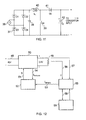
- FIG. 12 is a schematic drawing of a cell control system in accordance with an embodiment of the invention.
- FIG. 13 is a graphical illustration of the current versus voltage characteristics of ER and EW cells.
- FIG. 14 is a side view as illustrated in FIG. 2 , further showing the electrical origin of ER cell characteristics
- FIG. 15 a shows an electrical circuit representing ER cells
- FIG. 15 b shows an electrical circuit representing EW cells
- FIG. 16 is a front view of an electrode wherein regulators have been inserted between the electrode lugs and the bus bars;
- FIG. 17 is a front view of an electrode wherein regulators have been incorporated into the lugs
- FIG. 18 is a front view of an electrode wherein two regulators have been incorporated into a single regulator separating the main plate with the lug beam;
- FIG. 19 is an illustration of a modification to the embodiment shown in FIG. 18 with multiple regulators
- FIG. 20 a more mechanically robust version of the arrangement shown in FIG. 19 ;
- FIG. 21 is an end-on perspective of the arrangement shown in FIG. 20 ;
- FIG. 22 is a end-on perspective of the arrangement shown in FIG. 20 , wherein the regulators have been positioned in an alternative arrangement;
- FIG. 23 is a side view of a tank, illustrating how the power supplies may be carried on a support bar above the tank contacting electrodes via sprung pins in accordance with an embodiment of the invention
- FIG. 24 is a top view of the arrangement shown in FIG. 23 ;
- FIG. 25 is a top view of a tank, where two or more support bars are employed in the support bar arrangement;
- FIG. 26 is a side view of the tank, illustrating how a support bar system can be used to drive cathodes
- FIG. 27 is a top view of the arrangement shown in FIG. 26 ;
- FIG. 28 shows how frames may be removed and stacked
- FIG. 29 is a top view illustrating a configuration of support bars in accordance with a further embodiment of the invention.
- FIG. 30 shows a method of removing support bars and cover assemblies
- FIG. 31 is a side view of the upper ends of three electrodes, illustrating a method of using a cross member resting on anodes to support a cathode and regulator;
- FIG. 32 is an edge view of a three-layer cathode plate in accordance with an embodiment of the invention.
- FIG. 33 is a top view of an electrode configuration illustrating a means of moving plates in a tank in production-line flow
- FIG. 34 shows a longitudinal arrangement for production line flow illustrated in FIG. 33 ;
- FIG. 35 shows an arrangement of longitudinal flow when anodes, cathodes and power supplies move together
- FIG. 36 shows a modification to the arrangement shown in FIG. 35 ;
- FIG. 37 is a circuit diagram of a buck regulator with a synchronous rectifier carrying the freewheeling current
- FIG. 38 is a circuit diagram of a buck regulator adapted for driving cathodes
- FIG. 39 identifies the physical elements in operation in conjunction with the circuit shown in FIG. 38 ;
- FIG. 40 is a circuit diagram of a simplified switched-mode regulator to be used with other switched mode regulators in time-interleaved fashion so as to maintain a constant current in the hanger bar;
- FIG. 41 is a circuit diagram of a multiphase buck converter.
- FIG. 42 is a schematic diagram of a power management system in accordance with one aspect of the invention.
- FIG. 3 the illustration shows a tank arrangement that is common in prior art electrowinning and electrorefining plants. Multiple cathodes 1 are connected in parallel and multiple anodes 2 are connected in parallel to increase the total cathode surface area. There are twice as many IEGs as cathodes.
- FIG. 4 shows a prior art system having a multiplicity of tanks 5 connected in series.
- An interconnector 6 connects the tanks and is in practice not a single cable but multiple connections are made via equaliser bars which ensure connection is made between tanks at multiple points.
- the inventor has realised that to achieve accurate current density on both sides of the cathode plate, it is advantageous to control the current in the IEG or to individual cathodes.
- the invention described herein offers the control of current in either the cathode or the IEG according to the version the user deems most appropriate, with most accurate control of current density being obtained when the IEG current is controlled.
- the inventor has realised that the efficiency of the electrorefining or electrowinning process can be improved by individual cell control.
- each cell current is not individually controlled, one reason plate separation has to be large is to keep current density largely unaffected by errors in the plate separation or by problems with plate flatness. If the current in each cell is individually controlled, the current density can be made insensitive to plate separation and plate distortion and therefore the plates can be placed closer together. This in turn reduces the cell voltage and hence the power consumed by the cell for the production of a given amount of metal.
- the efficiency of each cell is sensitive to current density in the cell.
- the ability to hold the current density at the desired value enables the cell to work at optimum efficiency.
- the current density needed for optimum efficiency may vary during the refining or winning process.
- the invention permits the target current density to be altered dynamically according to cell conditions which may be sensed from the cell voltage or other measured parameters (e.g. electrolyte strength or temperature).
- a power conversion system (which can also be regarded as a power supply) is therefore provided for electrorefining or electrowinning cells in which power is taken from a relatively high voltage supply (ac or dc) and converted at the cell location to low voltage dc to supply a single cell so that in a plant of many cells each cell will have its own power converter.
- the power converter is adjacent to or part of the cell and is operated as a current source, thereby ensuring control of the current density for each cell.
- the current density can be modified locally according to the condition of the cell or the cell condition can be reported to a central control system which calculates the optimum current for that cell and commands the power converter to deliver the desired current.
- the power converter may feed current to a cathode electrode with the anodes on each side of the cathode connected together and to the converter. It will however be appreciated that in this arrangement there is no control over how the cathode current divides into the two individual cells (one on each side of the cathode), but this arrangement is more suitable for retrofitting to existing ER and EW tanks
- FIG. 5 shows how the electrodes may be supplied when the interelectrode gaps (IEGs) are driven by power converters 9 .
- the alternating cathode plates 1 and anode plates 2 are marked A C A C A and are viewed end on (i.e. from above in a vertical plate system).
- the power converters 9 are represented by circles.
- the plates (and hence the interelectrode gaps 3 ) may be supplied from both edges (corners) using all the converters shown ( 9 A to 9 H inclusive). Alternatively, the plates may be supplied from one edge (corner) by using only converters 9 A to 9 D inclusive.
- the plates may be supplied from both edges (corners) but with the power converters only acting on alternate interelectrode gaps (converters 9 A, 9 C, 9 F and 9 H being active). Considerations such as reducing converter count, optimal converter power and obtaining even current distribution determine which converter distribution is employed.
- the electrodes 1 , 2 may be driven (rather than the interelectrode gaps) as is shown in FIG. 6 .
- This configuration is particularly (but not exclusively) applicable when the converter is a buck regulator inserted between the conventional bus-bar distribution system and the plate, the configuration of which will be explained in more detail below.
- the alternating anode plates 2 and cathode plates 1 are marked A C A C A.
- the power converters 9 are represented by circles.
- the converters 9 A to 9 J have one terminal connected to a plate and the other connected to a common bus 10 to which the voltage 0V has been assigned.
- the plates can be supplied from one side using converters 9 A to 9 E inclusive or from both sides when converters 9 A to 9 J inclusive are employed.
- the converters 9 A, 9 C, 9 E, 9 F, 9 H and 9 J would supply the anode plates with current at full cell voltage (0.4V in the example above). Again, the number of converters employed could be reduced by operating converters 9 A, 9 C, 9 E only or 9 A, 9 H, 9 E only.
- the anodes could all be connected to a common bus.
- converters 9 B, 9 D, 9 G and 9 I would supply the cathodes (with ⁇ 0.4V in the example).
- the number of converters could be halved by using only converters 9 B and 9 D or only converters 9 G and 91 .
- the converters could be staggered between different sides of the tank. It will be recognised that where, as in this example, all the anodes are common and the cathodes only are driven that the current in the cells as defined by a pair of electrodes and an associated interelectrode gap is not under individual control.
- the converter circuits described herein represent likely candidates for the type of circuit to be used. It will be understood that there are a variety of methods for converting dc to dc or ac to dc which may be applied in the systems described.
- the examples given herein are double-ended converters but single-ended converters may be used.
- the rectification process illustrated in the circuits herein employs synchronous rectification. However, if the power loss entailed was not a significant consideration, simple diode rectifiers (Schottky or PN) could be employed.
- the power conversion process uses high-frequency switched-mode technology which provides a converter which can be small, lightweight, efficient and highly controllable.
- FIG. 7 shows how the converters of FIG. 6 may be incorporated in the plate configurations conventionally employed.
- FIG. 7 a shows in a traditional system how electrode projections, herein described as lugs 11 rest on bus bars 12 to make a connection between the electrode plates and the bus bars.
- FIG. 7 b shows, a converter or regulator circuit 9 can be inserted between the lug 11 and the bus bar 12 to regulate current flow between the lug 11 and the bus bar 12 .
- a powered unit 13 may be inserted between the lug 11 and the bus bar 12 .
- This unit can increase the voltage available to the electrode connected to lug 11 by adding to the voltage of the bus bars 12 (subtracting from the voltage of the bus bar 12 if it is a negative bus bar). Connections are made via contact plates 15 a and 15 b separated from each other by an insulating layer 16 .
- the lug 11 is part of a hanger bar supporting an electrode plate when the electrode is a cathode.
- FIG. 8 shows how the converter power supply circuit 9 may be implemented.
- a transformer 20 is used because of the high voltage ratio which will typically exist between the converter input voltage and the converter output voltage.
- the use of a transformer permits power semiconductor switches to operate with a duty cycle which gives a good form factor to the current in these switches thereby minimising power loss.
- the primary of the transformer 20 is a full-bridge inverter but it will be understood that a half-bridge inverter may be used.
- the transformer operates at a high frequency to reduce the size and cost of the transformer and any other passive components employed (e.g. capacitors). This high frequency may be from 20 kHz upward.
- switching devices 21 Q 5 to Q 8
- other semiconductor switches such as IGBTs or BJTs can also be applied here.
- a capacitor 22 is provided to circulate high-frequency switching currents.
- the output from the secondary winding is rectified in a full-bridge, full-wave rectifier to give dc for use in the cell.
- the body-drain diodes of the power MOSFETs 23 could be used to rectify the ac output of the secondary winding of the transformer so that the end A of the cell 24 was positive with respect to end B. However the forward voltage drop across these diodes would result in significant power loss in the MOSFETs.
- the MOSFETS are therefore advantageously operated as synchronous rectifiers. Their channels are turned on when the body-drain diodes are expected to be conducting (i.e. the MOSFETS are operated in synchronism with the switching devices in the primary side of the converter).
- the Rds(on) of each MOSFET can effectively be made as small as necessary either by choosing a suitably rated MOSFET or by connecting MOSFETs in parallel effectively to form one MOSFET switch. By this means power loss in the MOSFETS 23 can be kept to a reasonable level. For instance, if the converter outputs 300A at 0.4V dc, MOSFET switches with an Rds(on) of 0.1 mOhm would create a voltage drop across them of 30 mV.
- N-channel MOSFETS are generally preferred because for a given Rds(on) the price is usually lower but it will be understood that N and P channel MOSFETS can be used in any combination if required.
- the Rds(on) of a 0.8 mOhm MOSFET may be made up of 0.3 mOhm of silicon resistance and 0.5 mOhm of package resistance when packaged individually.
- each of the MOSFET switches 23 may be regarded as a bilateral switch (that is, capable of blocking in either direction and capable of conducting in either direction).
- the secondary bridge can be switched so as to produce a positive output at B relative to A on both half cycles of the transformer secondary voltage waveform (i.e. the cell voltage and current flow are reversed).
- a temporary reversal of cell polarity has been shown to have a beneficial effect in some circumstances (e.g. restoration of cell efficiency or reduction of metal spikes on the plates).
- the MOSFETS can be connected either way round in any part of the bridge for convenience of control. If reversal is required at higher voltages (above about 0.7V) the switches Q 1 , Q 2 , Q 3 and Q 4 can be replaced by a pair of anti-series MOSFETs.
- Capacitance may be added across the cell 24 to smooth the voltage waveform at the cell. If there is significant inductance in the cell and associated wiring, a circulating current path can be provided by turning on a pair of transistors (for example Q 1 and Q 2 ) in order to control circulating currents.
- CT 1 and CT 2 may be located on the primary and secondary side respectively to derive a signal which is related to the dc output current from the rectifier bridge.
- CT 1 measures a current which contains the primary magnetising current and the reflected secondary load current. This measurement may be accurate enough for the purpose of controlling the dc output current of the converter.
- the dc output current may be measured directly at the output using some form of dc current transducer (e.g. Hall effect).
- the transformer employed preferably has low leakage inductance since large values of current are provided by the secondary winding.
- a planar transformer with interleaved primary and secondary windings can provide the low leakage inductance required as well as having a conveniently low profile and being suitable for conduction cooling.
- the synchronous rectifier MOSFET switches consist of a number of MOSFETS in parallel
- Torroidal-cored transformers are also known to provide low leakage inductance.
- the power conversion circuit is suitably configured so that it can be made reversible. That is, the voltage and current flow may be reversed. A period of reverse current flow has in some processes been found to be beneficial in promoting higher efficiency when forward current flow is restored.
- the employment of a converter local to the cells for each cell enables this technique to be used in the most advantageous manner.
- PWM Pulse Width Modulation
- FIG. 9 shows a converter circuit in which a transformer 30 with a centre-tapped secondary winding 31 is used.
- CT 1 and CT 2 indicate suitable locations for the current transformers for the purposes of obtaining the dc current output feedback signal.
- Secondary side transistors Q 1 and Q 2 are operated as synchronous rectifiers as before. The ability to provide reverse current flow in the cell is limited to output voltages of about 0.3V. If reversibility is required at a higher voltage, Q 1 and Q 2 can be replaced by a pairs of anti-series MOSFETs which are then be made to behave as bilateral switches.
- the power converters are rated according to the size of plates being driven.
- the cells can be made larger or smaller than is usual to take advantage of the technology described herein. Separation distances between electrodes need not be the values conventionally used. Indeed, one of the advantages of the present invention is that plate separation can be reduced because of more accurate and faster control of the current in the cell as well as the potential to adapt the cell current density to suit prevailing conditions. A smaller plate separation leads to a reduction in cell resistance resulting in less power loss in the cell. Plate configuration options, including variations in plate separation are explained in more detail below.
- the power converters can be continually or transiently operated on some other control principle (e.g. operate as a voltage source).
- the power converters and their control systems may be made submersible (in the electrolyte). Contact with the plates may be at the bottom of the plates when gravity and the weight of the plates can produce an electrical contact between the plates and contact strips (probably of a non-corroding, non-consumable material) on the bottom of the tank.
- the converter may be set to produce a current of a fixed value.
- the magnitude of the current delivered to the cell can be sensed directly by a dc current sensing method if required but because the power conversion process takes place close to and on behalf of a single cell, the current signal can conveniently be sensed within the power conversion process (for example by the use of an ac current transformer at some convenient point in the switched-mode power conversion circuit as discharged hereinbefore with reference to FIGS. 8 and 9 .
- the control system may adapt the current density to the state of the cell.
- the state of the cell can be measured using a number of variables—for instance the cell voltage.
- Other parameters may be monitored, for instance electrolyte temperature, electrolyte concentration, and optical evidence of spike growth.
- Other characteristics may also be used to monitor cell condition. For instance the cell current may be turned off briefly and its recovery when a certain voltage or current is applied may be observed.
- the present invention may have the capability to hold the current in the IEGs (or optionally the total current to a cathode) to an accuracy dependent only on the accuracy of the current sensor or sensors employed to measure the current.
- An accuracy of 0.1% is achievable with dc or ac current sensors.
- Lower cost current sensors can achieve an accuracy of 1%.
- the standard deviation in current densities between the many cells in an ER or EW system will be far smaller than that achieved by current practice leading to fewer shorts and higher quality copper.
- DC current measurement
- AC current measurement
- AC current measurement can be carried out quite economically by using a current transformer.
- the anodes, cathodes and IEGs in the invention are fed with DC. But when these DC currents are generated or regulated using switched-mode technology there are AC current signals available which may be measured using low cost AC transducers based on the well known AC current transformer method. Where multiple current paths exist in the converter or regulator it may only be necessary to measure accurately the absolute value of the contribution of one of those paths. The current measurement arrangement in the other paths is only then required to ensure that the current in all the paths is equal, not to make an absolute measurement. The total current measurement can be obtained by multiplying the one absolute measurement by the number of paths.
- DC current measurement is also possible by employing a magnetic circuit which encircles the conductor.
- a Hall effect sensor is inserted in a slot in the magnetic path.
- the current is then measured by measuring the flux in the magnetic circuit using either an open loop method or the flux-null method. This arrangement is practical but may be bulky and expensive.
- FIG. 12 illustrates schematically a control system.
- the cell power converter 50 is supplied from a 48V dc supply 48 and provides a current-controlled output to an electrorefining or electrowinning cell 49 .
- the required current level is achieved by use of a suitable switching duty cycle in the converter 50 controlled by a PWM duty cycle signal 51 .
- This signal is derived in a current control loop 52 by comparing a current demand signal 53 with a current measurement signal 54 representing a measured current.
- the current measurement signal 54 is derived from current detectors in the converter 52 or at its output.
- the current demand signal 53 can be preset or it can be derived from a cell controller 55 which measures cell voltage 56 and possibly derives information from other relevant sources 57 (e.g.
- the cell controller may also have two-way communication 58 with a central control facility for the purposes of downloading a crop session history, or reporting cell condition and operating parameters at any time and for receiving revised instructions as to how the cell should operate.
- the use of a power converter for each cell simultaneously provides a current measuring facility for that cell.
- variables such as cell voltage can also be measured as part of the control process and are therefore available for analysing and reporting on cell condition.
- Cell condition can be measured by the converter being commanded locally or remotely to perform a task (such as a step change in current or adding an AC component to the DC converter output current) to enable cell condition to be observed.
- Cell performance can be enhanced by commanding (locally or remotely) the cell to perform performance enhancing manoeuvres such as a brief current reversal.
- an interval of current reversal may yield signals which give a good indication of cell condition. Such a measure may need to be applied simultaneously to two the cells associated with a single cathode.
- a visual or audible warning system may be incorporated into several or every converter and its control system to warn of problems.
- a display on a converter can inform a passing operator of the associated cell condition or performance.
- the control system allows information about each plate to be obtained from current and voltage measurements (and other variables if measured) so that data on plate quality, size, flatness and alignment can be returned to a central control system for analysis.
- This information can be used in a quality control and quality improvement scheme thereby increasing the efficiency of the whole processing plant.
- a benefit of the invention is the ability to obtain information about individual cells and electrodes through monitoring electrical quantities at the individual converters.
- An advantage of the invention is that the voltage at which the cells are supplied is not determined by a trade-off between safety and efficiency. While the traditional approach of operating tanks in series may raise the dc voltage employed and hence the efficiency of the rectification process, the danger of electric shock and dangerous fault conditions is increased. With controlled local conversion the power supply to the converters can be of any appropriate voltage since this power will be supplied through insulated cables. However, from inspection of FIGS. 4 and 5 we expect that no electrode is more than one cell voltage above earth potential. This will also minimise leakage current to ground through spilt electrolyte. Where, for example, there are many cells in a tank, one electrode (for example an anode) may be grounded so that all other cathodes and anodes remain within a few volts of ground potential.
- a further advantage of the invention is that fault current resulting from a short circuit between plates can be controlled and the presence of a short circuit detected quickly.
- the change in V-I characteristics of the cell can be used to detect the growth of a metal spike before it forms a complete short circuit enabling the potential fault to be reported and remedial action to be taken before a complete short circuit is formed.
- FIG. 16 illustrates an identical configuration to FIG. 7 b but with both sides of the electrode shown for completeness.
- the electrode lugs or hanger bar ends 11 rest on a regulator or converter 9 and a bus bar 12 .
- the converter 9 controls current flow between the lugs 11 and the bus bars 12 .
- Multiple power supplies can optionally be used for driving either cathodes or IEGs as shown in FIG. 16 .
- the other converters can take up the load, there by permitting a cathode or cathode side to harvest its full quota of metal in the allotted time despite the failure of a power supply.
- the plurality of converters associated with each cell may be under the control of a common control system and to each supply an appropriate fraction of the current required by the cell. If the plate was operating in conjunction with electrodes on each side of it (that is driving the cells on each side of it as shown in FIG. 5 ), it is therefore possible that each lug, for example as shown in FIG. 16 , would have two converters attached making a total of four per plate (two per cell where a cell is here used to describe the gap between one anode plate and one cathode plate).
- FIG. 17 illustrates an embodiment in which a plurality of regulators 9 are incorporated into the lugs 11 , but electrically still fulfilling the same role as those in the configuration illustrated in FIGS. 7 ( a - c ) and 16 .
- the two regulators may be combined into a single unit and moved to between the bar 66 with lugs 11 and the electrode plate 67 as shown in FIG. 18 .
- FIG. 20 shows a more mechanically robust version of the arrangement shown in FIG. 19 as will now be described with respect to FIG. 21 .
- FIG. 21 illustrates the hanger bar 66 of FIG. 20 end on rather than face-on to the hanger bar 66 and plate 67 .
- the hanger bar 66 may be divided into two parts 66 a and 66 b to give mechanical balance.
- the hanger bar is electrically insulated from the plate 77 by insulators 68 .
- a connection bolt 69 is preferably made of insulating material or is otherwise insulated either from the hanger bars 66 a and 66 b or the plate 69 . Current passes (in the case of the cathode) from the plate to the hanger bar through the regulators 65 .
- the regulators 65 may be placed in an alternative position.
- the regulators 65 are situated above the hanger bar 66 , the electrical insulator 68 also providing thermal insulation and the hanger bar 66 dissipates heat from the regulators 65 into the ambient air.
- An electrical conductor 70 provides an electrical connection without permitting much heat to flow into the converter 65 .
- the hanger bar or lug resistance may not be insignificant.
- the hanger bars or electrode lugs rest on and make contact with bus bars running along the edges of the tanks
- the surface to surface contact has resistance which can insert a voltage drop (typically of the order of 20 mV for copper ER) in the electrode path.
- the total voltage drop for both electrodes can be 40 mV.
- the inventor has realised that this is not only responsible for a serious loss of energy, but also provides a further potential source of imbalance of current density between sides of the cathode electrodes since anodes on each side of a cathode plate may not be at equal potential if the potential drop in their contacts is not the same for each anode.
- FIG. 10 shows a buck regulator which may be used as an alternative to individual converters supplying individual cells but still applying the principle of using current measurement and current control to improve cell performance.
- the converter comprises power MOSFET 32 , inductor 33 , capacitor 34 and diode 35 .
- Vin and Vout will be of closer in magnitude than in the converters previously discussed. Indeed, the input voltage may only be a small percentage above the output voltage and the duty cycle of the converter switch may be close to 100%.
- the circuit does provide current control and an opportunity for current measurement using an ac current transformer (with reset) if desired.
- the converter can be inserted between the bus bars and the plates of a conventional electrorefining or electrowinning system.
- Diode 35 can be replaced by a synchronous rectifier (another power MOSFET) to increase the efficiency of the regulator.
- Inductor 33 may be dispensed with (along with capacitor 34 ) if ripple current in the cells is acceptable.
- Control is applied to the regulator in the manner previously discussed for other converters. Where this type of converter is retrofitted to existing plant it is likely that the dc bus voltage (input to the converter) will need to be raised slightly to give some headroom within which the PWM control circuit can operate.
- An auxiliary converter or auxiliary supply may be needed to provide a power supply of adequate voltage for the control circuitry. Current can be measured by an ac current transformer CT 1 25 as long as the duty cycle is less than 100%.
- the preferred solution is to use a multiphase design within each converter.
- the advantage of the multiphase solution is that inductor sizes become reasonable. Inductors that are of too high a current value while at the same time having too high an inductance value are not optimised. This has advantages too in the transformer version in which leakage inductance between the primary and secondary windings, which can give rise to loss of output voltage, can be ameliorated by the multiphase approach.
- FIG. 11 shows a converter operating from an ac supply 36 with a power-factor correction (PFC) circuit at the front end in accordance with an embodiment of the invention.
- the ac to dc conversion on the primary side could take place using a simple rectifier and bridge rectifier but with large loads power factor correction is usually required at some point. If power is distributed to the converters at, for example, 48V dc, the 48V dc supply can be generated at suitable points throughout a tank house with power factor correction.
- FIG. 11 shows a PFC circuit which will be readily recognised by a person skilled in the art of power electronics.
- the ac input is full-wave rectified a full wave rectifier comprising diodes (D 1 to D 4 ) to produce a full-wave rectified voltage waveform.
- a capacitor 38 is a small by-pass capacitor for high-frequency switching current components.
- An output of the rectifier is provided to an inductor 40 , a diode 41 and a reservoir capacitor 42 .
- a semiconductor switch 39 is operated in such a manner that the current through the inductor has the same waveform (apart from high-frequency ripple) as the full-wave-rectified voltage waveform. After steering by the diodes in the full wave rectifier bridge 37 , this current waveform emerges as an ac current waveform in phase with the ac voltage waveform. Typically there is a control loop which maintains the average voltage across the reservoir capacitor 42 at the desired value. This dc output is then used as the input to the individual cell converters described elsewhere.
- An advantage of employing multiphase converters is that the current ripple in the output can be reduced to zero in an economical fashion. It is generally unacceptable for a dc power supply to deliver a large amount of ripple in its output voltage or output current. Hence switched-mode converters are usually endowed with a filter arrangement which reduces these ripple components to acceptable magnitudes. However filter components are expensive. If a multiphase converter is used and it has a duty cycle of 1/N where N is the number of phases employed, the ripple current can be reduced to zero with no further filtering. Output voltage (and hence output current) can then be controlled by varying the input voltage to the multiphase supply. If the converter derives its input from an ac-dc PFC stage, the PFC stage can be controlled so as to vary its output voltage. A 2:1 variation in the output voltage of commonly used PFC stages is possible which will be adequate to effect the degree of variation of the voltage and current required to be delivered to EW and ER cells in normal operation.
- a regulator is inserted between the bus bars of a traditional tank system and the plate of the electrode, typically a cathode
- adjustment can be made to the current entering the plate in the conventional tank house system in which power is supplied from a central source.
- the voltage supplied by the traditional central dc power source may be elevated slightly to give the regulator some headroom within which to operate so that it can permit normal current to flow, notwithstanding the voltage drop inserted by the regulator.
- a power supply may be inserted between the electrode and the traditional system bus bars.
- this power supply may add to the voltage difference between anode and cathode.
- the cathode bus bar might typically be at ⁇ 0.32 V.
- extra voltage can be injected into the anode-cathode path via the power supply to say, 0.39V adding 0.07V to the total available voltage.
- a 600 Amp, 0.07V auxiliary power supply would be required.
- the power supply may be a well known buck regulator circuit or other well known switched-mode power supply circuit.
- This auxiliary power supply may or may not be capable of shutting off current flow to the electrode (for example in the case of a short) depending on the circuit used for the power supply.
- Most of the power used in the cell will come from the conventional bus bars and centralised supply and the power being delivered from the auxiliary power supply will only be a fraction of the total, this fraction being determined by the proportion of total voltage supplied by the auxiliary power supply.
- the advantage of this is that only a fraction of the total power consumed in a tank has to be delivered to the tank by a new power supply arrangement at the tank location.
- This modest amount of power may be delivered by traditional means (e.g. cables, contacts or connectors) or it may be delivered by alternative means such as inductive power transfer.
- the regulators or power supplies are integral parts of the hanger bar and/or electrode plate assembly
- heat generated in the regulators or power supplies can be conducted into the plate and thus the electrolyte.
- the electrolyte is typically at 55 to 60 degrees C. for ER and 40 to 45 degrees C. as for EW (for example in copper processes) and the heat generated in the regulators can be reduced to almost zero by using large numbers of power MOSFETs in parallel, cost being practically the only limiting factor in reducing the resistance of the parallel MOSFET combination in which case it is likely that the electrolyte will heat the transistors rather than cool the transistors.
- the transistors should be thermally isolated from the plate which dips into the electrolyte and the transistors provided with a separate cooling arrangement.
- This could be a finned, ambient-air cooled heat sink.
- the hanger bar could be used as a heat sink.
- the equaliser bar will aim to connect together cathodes or anodes on either side of the tank so that across each tank anodes and cathodes are at a uniform voltage. Another objective is to maintain a path for current to flow to or from an electrode should one of its lugs (hanger bar ends) become contaminated and fail to connect properly to the anode or cathode bus from which it should collect or deliver current.
- a positive and a negative bus rail are both present along the edges of each side of a tank with a potential across them equal to the voltage drop between the anode and cathode of a single cell.
- This can be used as a power supply for a converter located on the cathode which raises or lowers the cathode potential above or below its normal voltage in order to fine-tune the current drawn by that cathode.
- the equalising bars can be employed in a retrofit to supply ac to power supplies on the cathodes or at the side of the tanks when supplying the IEGs.
- a three-phase ac power supply system will usually be the source of power for a tank house.
- a copper ER tank with 60 cathodes will require about 14 kW.
- a copper EW tank with 60 cathodes will require about 75 kW. Both these power levels could be supplied from a single-phase transformer.
- it may be desirable to present a balanced load to the three-phase supply which would almost certainly be supplying a metal refinery or metal EW system.
- different phases of a three-phase system should not be in close proximity to each other because in a three-phase system the line-to-line voltage is substantially greater than the line to neutral voltage.
- a good arrangement therefore would be that each tank operates from a single phase but that tanks are divided into blocks of three with each one being supplied from one of the phases of a three-phase, four-wire supply.
- both conductors When the power supplies are fed from single-phase AC, it may be convenient to use both conductors as live conductors so as to reduce the live to ground voltage in the interests of safety. So, for example, rather than supplying the power supplies from two conductors, one at 230V with respect to ground (the live) and one at 0V with respect to ground, it will be safer to supply both conductors with 115V with respect to ground (that is, two anti-phase lives). This could be particularly important where the AC conductors run along the sides of the tanks in an exposed manner. For example, adjacent edges of two side-by-side tanks could carry live A at say, 57V while the other sides of these tanks could carry live B (in anti-phase to live A) at 57V. Hence a shock at 114-115V could only be obtained by touching the conductors on opposite edges of any given tank. A Residual Current Circuit Breaker can be used to protect users from shocks resulting from touching any of the 57V rails.
- transformers can be placed at suitable locations in a hall containing many tanks to step down the voltage in stages so that power can be supplied to selected locations at a high voltage and there transformed down to a lower voltage for distribution to the individual converters. Hence power transmission takes place at a voltage appropriate for the level of power being transmitted resulting in reduced electrical power loss.
- power may be converted at selected locations to a lower voltage dc supply. Power factor correction can be applied at these locations or at individual cell converters if they are supplied with an ac supply. Details of the various embodiments will be explained in more detail below.
- a power supply of a voltage close to the cell voltage can be used.
- a buck converter such as that illustrated in FIG. 37 can be employed between the presently used dc bus-bar power distribution system and the electrodes.
- FIG. 37 shows a switched-mode buck regulator as described in FIG. 10 except that the diode 35 has been replaced by a power MOSFET 130 operating in the synchronous rectifier mode in order to improve the efficiency of the circuit.
- the current entering and leaving a plate would be controlled by a converter (or converters) placed between lugs and the dc low voltage bus bar.
- a converter or converters placed between lugs and the dc low voltage bus bar.
- the current setting for each converter would have to take this into account and where the current level was modified during operation the separate converters would have to be informed of the change or would need to communicate with each other.
- the use of synchronous rectification can be used in the freewheeling part of the circuit to increase the efficiency of the regulator.
- EW the anodes are permanent but in the case of ER the anodes are soluble. Hence in the case of ER the regulator is more likely to accompany the cathode.
- FIG. 38 shows the circuit of FIG.
- Capacitor 131 has been added to provide a path for high-frequency ac currents.
- the inductor 33 along with the capacitor filter 34 smooth the switched waveform at the drain of MOSFET 32 .
- the presence of the inductor 33 in this filter circuit makes it necessary to include a second MOSFET 130 to provide a circulating current path for the current in inductor 33 when MOSFET 32 turns off
- MOSFET 130 these are relatively expensive components.
- FIG. 39 identifies some physical elements of the circuit shown in FIG. 38 .
- the cell 24 is composed of the electrolyte physically present between a cathode plate 132 and an anode plate 133 .
- a circulating current in inductor 33 circulates through MOSFET 130 when MOSFET 32 turns off.
- the branch 134 of the circuit provides an dc source or sink at anode potential for the circulating current. By virtue of the capacitor 34 it is also an ac ground.
- Branch 135 of the circuit connects branch 134 to the anode as well as the positive terminal of the power supply and may have a distinct physical reality.
- the current in the hanger bar can be kept approximately constant in which case there will not be any high rate of change in the current in the hanger bar which could interact with parasitic inductance to cause over voltage of the MOSFETs. Even so, it is possible that high values of di/dt interacting with parasitic inductance will cause over voltaging of the MOSFETs used for the switches. However this need not be a problem as most MOSFETs are rated for operation in avalanche. To further reduce the possibility of any excessive voltage due to parasitic inductance the rate at which the MOSFET 32 is switched (and hence di/dt) may be reduced—that is to say, its turn-on and turn-off time may be lengthened.
- the amplitude of the switching control waveform applied to the gate of each MOSFET may be kept at a relatively low amplitude to prevent over-abrupt switching of the MOSFET.
- a major advantage of a switched-mode regulator such as this is that low cost ac current sensors can be employed to provide accurate measurement of the current for monitoring and control purposes.
- MOSFETs 32 are united by large conductors which help to reduce the parasitic inductance between the MOSFETs 32 .
- the regulators in FIG. 39 may be reduced to a single MOSFET 32 each as shown in FIG. 40 .
- FIG. 41 is a multiphase buck regulator circuit suitable for stepping down voltage in high-current situations.
- An input supply 140 is converted to an output 141 of a lower voltage.
- MOSFET switches 142 , MOSFETs 143 used as a synchronous rectifier, and an inductors 144 constitute the components of each phase. All phases contribute to the output 141 which is smoothed by a capacitor 145 . The output is supplied to a cell 146 .
- FIG. 42 is a schematic diagram of one possible overall power management system arrangement.
- the cell load represented by resistor 146 is supplied by a buck (single phase or multiphase) converter 150 .
- Converter 151 creates a dc supply 152 from an ac supply 153 (e.g. 230V, 50 Hz).
- This converter 151 may include a power-factor correction stage.
- An intermediate supply 152 may be any convenient dc voltage but may also be the dc voltage derived from a power factor correction stage and may contain substantial voltage ripple as well as being of a voltage greater than the peak voltage of the ac supply 153 .
- the intermediate voltage supplied to it at the intermediate voltage rails 155 should not be too far removed from the output voltage (i.e. the cell voltage).
- the input voltage of this converter should not be much more than ten times the output voltage when the converter is a simple buck converter.
- an intermediate converter 154 may be required to convert the output voltage of converter 151 to a voltage appropriate for input to the converter 150 .
- the input voltage to the converter 150 can be much higher when it is a transformer based converter, examples of which were described with respect to FIGS. 8 and 9 .
- a bar or frame resting on the either the tank sides or on the electrodes themselves and passing electricity to the electrodes via sprung contact pins or shafts which press onto the electrodes or their hanger bars.
- the pins are connected to their respective power supply terminal via flexible conductors. These conductors provide an opportunity for the incorporation of dc current transducers if required, the flexible conductor being able to pass easily and conveniently through the window of commonly available dc current transducers.
- the support bar may be independently supported or it may be supported by the sprung pins resting on the electrodes.
- FIG. 23 shows how the cells, and specifically the IEGs in a tank may be driven from power supplies carried on a bar 75 above the tank 76 .
- the tank 76 stands on the ground 77 and is viewed side-on—that is, looking at the electrodes edge-on.
- the tank may be of any extension and contain any number of anodes and cathodes.
- the tank contains cathodes 1 and anodes 2 .
- Items 79 are hanger bars or lugs associated with each electrode which support these electrodes on insulated bearers along the side of the tank 76 .
- the power supplies 80 which supply dc to the IEGs are carried on a support bar 75 .
- Metal pins or shafts 81 pass though or beside the support bar 75 and are insulated from the support bar 75 by an insulating sleeve if the support bar 75 is a conductor. If the support bar 75 is made of insulating material then the insulating sleeves are not required.
- the pins 81 are spring loaded so that once in contact with the electrodes on which they press they are to some degree compliant. The pins 81 make contact with the hanger bars (typically in the case of a cathode) or with the electrode surface (typically in the case of an anode).
- the hanger bars may have a special metal patch where contact is made by the pins 81 to ensure good electrical contact.
- the electrodes e.g. of the anodes
- the power supplies 80 on the support bar 75 provide a supply of dc current which is fed to the anodes and cathodes. Wires 82 connect the positive output of the power supplies 80 to the anodes and connect the negative output of the power supplies 80 to the cathodes.
- the support bar 75 may be independently supported or it may be supported by the sprung pins 81 resting on the electrodes.
- FIG. 24 shows the same arrangement as in FIG. 23 but viewed from above.
- two or more support bars run the length of the tank as is shown in FIG. 25 .
- Two bars 75 are used in the illustration by way of example but any number of bars 75 may be employed.
- the bars 75 are joined at each end of the tank and where appropriate by cross members 83 , the whole assembly of cross members 83 and bars 75 therefore forming a frame.
- the advantage of a frame is that when placed on top of the tank, and particularly when supported only by the pins 81 bearing on the electrodes 77 and 78 . It will be appreciated that there are a variety of ways of making a stable frame all of which are encompassed within this invention.
- the power supplies may be carried on bars 75 or they may be carried on non-active bars or on a platform supported by the support bars 75 or by non-active bars.
- the power supplies may derive their power from, by way of example:
- Flexible cables may connect the frame or bar to these power sources.
- the cables can feed the bar or frame either at the end or ends of the bar or frame. Alternatively the cables can feed the bars or frames at some central or common point.
- the cables can bring power in either from an overhead distribution system or from a distribution system alongside the tanks or at the end or ends of the tanks.
- the flexible cable supply may optionally include a plug and socket connector for connection and disconnection.
- the power may be brought to the frame through pressure contacts carrying ac or dc.
- the frame can in this situation be moved without the need to disconnect any plug and socket system.
- One of the problems of the ER or EW environment is the presence of an electrolyte which can be deleterious to electrical contacts.
- the technique of inductive power transfer can be advantageously employed.
- the sender unit is effectively the one half of a transformer magnetic core and its primary winding while the receiver unit is the other half of the magnetic circuit and the secondary winding. No electrical conductors need be exposed in either half.
- the magnetic cores are brought together as closely as possible so that there is as little distance as possible between the magnetic cores. Ideally they should be in contact.
- the magnetic core material is likely to be damaged by the electrolyte, it may be necessary to cover the core surfaces in a thin protective film of chemically inert material.
- Various configurations of core shapes are possible (e.g. a blade within a forked core, a cone within a conical receiver or a simple E to E core or circular (pot type) core to circular core). Inductive power transfer would also remove the need for arc prevention schemes in the case where hot swapping is employed.
- FIG. 26 shows the side view of the tank (similar to that of FIG. 23 ).
- FIG. 27 shows the view from above (similar to that of FIG. 25 ).
- the power supplies 80 have two common positive terminals 84 and one negative terminal 85 .
- the negative terminal 85 of the power supply 80 is connected to the pins that feed a cathode via wires 82 .
- the positive terminals 84 of the power supply 80 are connected to the pins that feed adjacent anodes via wires 82 . Thus all the anodes are at the same potential.
- FIG. 29 shows an alternative orientation of a row of pins contacting the electrodes.
- FIG. 29 shows a view of a tank from above. Anodes 96 and cathode 97 are supported by lugs or hanger bars on the sides of the tank which are insulating. Support bars 98 run across the tank above the electrodes and lie in the same orientation as these electrodes. The support bars 98 carry sprung contacting pins 99 as before.
- the pins in one support bar may be connected together via flexible wire if the support bar 98 is of insulating material or the support bar 98 can be made of conducting material in which case it can provide the connection between pins. Insulating end-frame members connecting the support bars can give mechanical rigidity and form a frame. In the arrangement shown in FIG.
- the IEGs are driven by the power supplies 100 .
- a number of power supplies (in the example there are four although any number of supplies , including one, is a possibility) drive each IEG.
- the supplies are connected with their positive terminals connected to the support bar and pins above the anodes and the with their negative terminals connected to the support bas and pins above the cathode.
- the supplies operate in parallel. Since they will be current-mode supplies they may naturally share the current load according to the setting of each or if this arrangement has a tendency to lead to instability they may be connected together by signal wires so that their contribution to the total current is controlled in a coordinated manner.
- Pins 101 represent the connection points where connection is made between the power supplies and the support bars (if conducting) or the wiring system if the support bars are non-conducting.
- FIG. 29 One virtue of the arrangement shown in FIG. 29 is that if power supplies are located only at the extremities of the interelectrode gaps (that is, near the sides of the tank) the gap between electrodes is visible and accessible from above so that the state of the gap can be inspected visually and if necessary shorts between electrodes can be removed physically (for example by knocking them off with an insulating rod inserted between the electrodes).
- the multiple pin arrangement has the virtue of reducing this contact resistance since all the pins for one electrode are in parallel so that the total effective resistance is reduced by the multiple current paths which the pins provide.
- the weight of the frame may be enough to ensure good contact of the spring-loaded pins with the electrodes.
- the frame could also carry one or more mains transformers for reducing the mains power supply to the power supplies.
- the load on the frame could, for example, consist of one single-phase transformer, three-single phase transformers operating from the same mains phase or three single-phase transformers operating from three different mains phases.
- these transformers would step down from a voltage in the region of 1 to 3 kV to a voltage in the range of 110V to 250V for the supply of the power supplies.
- the step down mains transformers would be supplied by flexible cable form overhead or form the side of the tanks
- an overhead crane is available for loading and unloading electrodes from the tank and this can also be used for raising and lowering the frame bearing the transformers and the power supplies.
- FIG. 28 shows how frames may be removed from the tanks by overhead cranes and stored on top of each other to permit access to the electrodes. If a single bar is used it will be feasible to lay the bar in a carrier system running alongside the tank for that purpose. If a frame is used the frame can be rotated and hung vertically at some convenient location alongside the tank. Frames can be lifted without rotation and stacked on an adjacent tank as illustrated in FIG. 28 in which 90 is a tank viewed end-on. The tanks stand on the ground 91 .
- the power supply and pin assembly has legs 93 which rest on the tank sides in operation or which can be used to support a frame when standing on top of another one as shown.
- FIG. 30 shows an alternative arrangement for removing frame and cover assemblies when there is space available at the extremities of the tanks
- the power supplies, electrode-contacting arrangements and covers are removed in this example as two units 105 each covering half the tanks These units are lifted up to disengage from the electrodes and then moved longitudinally away from the centre of the tanks to allow an overhead crane access to the electrodes.
- the area between support bars and frame bars can be filled in with a solid sheet material or a fabric sheet so that the performs the additional function of covering the tank.
- Power supplies for the electrodes can be carried on these frames.
- the hoods often used to control the emission of mist can also be incorporated in the frames.
- Power supplies may be paralleled with one another by conducting support bars. However, if the pins are isolated from the support bar or the support bar is made of non-conducting material and the power supplies feed pins rather than the support bar, paralleling of the power supplies takes place on the electrodes. This may be advantageous for obtaining an even distribution of current in the electrodes.
- FIG. 31 is an edgewise view of the tank and the electrodes are viewed edge-on illustrating such an embodiment.
- Anodes 106 are suspended conventionally via lugs which rest on the sides of the tank.
- the cathode 109 and power supply assembly (comprising conducting cross member 107 and power supply 108 ) rests on the upper surface of the anodes. Either the cathodes or the IEGs may be driven by this method. If the IEGs are driven the supporting cross member 107 will need to have its two halves electrically isolated.
- the power converters could be connected centrally to the plates or sandwiched between plates. It is a benefit of the system that the supply of current to the plates can be considered as an issue separate from that of suspending the plates. The problem of voltage drop in the regions of contact between the dc source and the plate can therefore be substantially reduced or eradicated.
- the frame system described in the foregoing is used to supply dc current to the electrodes or electrode pairs.
- the power supplies can be carried by the electrodes.
- the converters can be carried on the cathode hanger bars and supply the cathodes relative to the anodes as described elsewhere in this description.
- the frame/bar and pin system can be used to supply ac to the converters, the converters themselves not being on the bar or frame but on the cathodes.
- the bar/frame system may alternatively be used to supply dc to converters or regulators located on the cathodes.
- Any frame arrangement may incorporate a central display panel to indicate the state of all the individual cathodes or IEGs in one place.
- This could for instance be a monitor display screen or a panel of LEDs.
- Such a display could be conveniently placed at the end of a tank next to a walkway.
- a cathode is fed by a power supply or regulator there is no control over how the current divides between the two sides of the cathode—that is to say between the IEGs.
- a cathode may optionally be composed of two metal sheets with an insulating layer between them.
- FIG. 32 shows how a triple-layer cathode can be used to allow the current density on either side of the cathode to be controlled independently.
- the three layers may be bonded together or glued together to mechanically form a single sheet but with its two sides electrically isolated.
- Each side of this “sandwich” cathode can then be independently supplied by separate power supplies or regulators 112 a and 112 b.
- Wires 113 and 113 b connect the converters or regulators 112 a and 112 b to respective metal plates 110 a and 110 b.
- the converters or regulators are supported by the hanger bar 114 . Hence the voltage with respect to the adjacent anode can be controlled for each side of the cathode plate.
- the metal sheets of the sandwich can be made slightly smaller in width and length so as to leave a margin of the insulating material around the periphery of the sandwich cathode on either side, thus giving a substantial tracking distance for any current which tries to pass from one side of the sandwich cathode to the other thereby putting a substantial resistance in the path of any such current flow.
- anodes and cathodes a new mobility which can be used to make the gap between anodes and cathodes adjustable. Between croppings the gap can be adjusted to overcome the problem in traditional system in which the width of the IEG increases from one crop to the next as the anode thins. This would allow the minimum possible voltage to be employed to drive each cathode or IEG at the required current or current density thus saving energy. Also electrode spacing can become an adjustable variable in the process of ER or EW so as to optimise the process. Conventional practice is to use a fixed width and to locate the anodes and cathodes a distance apart which minimises the chance of interelectrode shorts.
- the use of local power supplies to power the cathodes or IEGs facilitates the use of an adjustable IEG width. For instance, if the power supply is carried on the cathode hanger bar and supplied by ac input power from a flexible cable or contact sliding on a catenary wire, the cathodes are free to move.
- the anodes may also have a sliding contact for the return current path or have a cable connecting them to the power supply on the cathode.
- all the electrodes could be supported on wheels and the ac current collected through these wheels with a flexible cable or strap providing the necessary path for dc current between the power supply mounted on the cathode and the anode.
- the means of moving the electrodes could be on the electrodes or external to the electrodes.
- the wheels described above could be motorised.
- the time between crops in a present technology tankhouse is typically seven days. Hence there is no need for high speed motion or rapid IEG width changes. These could be effected by very low power, low cost motors or actuators.
- the electrodes could shuffle slowly to adjust their positions with respect to each other at a speed which would be barely observable.
- FIG. 33 An additional or alternative possibility is shown in FIG. 33 .
- a production-line approach can be adopted in which electrodes 120 progress along a single long tank 121 , starting at one end and emerging at the other end when they are ready to be harvested. By this means labour cost in the tank house could be reduced substantially. If a short develops or threatens to develop between electrodes, the separation between electrodes can be dynamically adjusted to cure or prevent the short. Otherwise electrodes could be moved as closely together as possible to minimise energy loss due to electrolyte resistance. Rolling devices 122 permit the electrodes to move along with their power supplies 123 .
- mobile electrodes can be used in a new orientation as is illustrated in FIG. 34 .
- the traditional orientation of the electrodes can be turned through 90 degrees as shown in FIG. 34 .
- the cathodes may move in production line fashion between static anodes, entering at one end of the process and emerging from the tank at the other end ready for their metal deposit to be harvested.
- the anodes are static. This arrangement requires that some form of sliding contact would be required to complete the dc electrical circuit between the cathode and the anode electrodes.
- a longitudinally oriented production system may be used as is illustrated in FIG. 35 .
- Cathodes 125 , anodes 126 and power supplies all travel together along the production line with either IEGs being fed by the power supplies or with cathodes being fed by the power supplies.
- the ac or dc power for the power supplies is collected from an overhead catenary with either both the parts of this supply being collected from catenaries or one part only being collected with the other part being though the rail system carrying the electrodes.
- FIG. 36 shows how a multiplicity of cathode and anode lines may progress along a production line as described in FIG. 35 permitting both sides of anodes to be used.
- anodes and power supplies can all travel together along the production line with either IEGs being fed by the power supplies or cathodes being fed by the power supplies.
- the ac or dc power for the power supplies is collected from an overhead catenary with either both the parts of this supply being collected from catenaries or one part only being collected with the other part being though the rail system carrying the electrodes.
- the width of the IEGs on either side of the cathode can be varied by moving the rails carrying the anodes closer to or further away from the cathode support rail. This can be carried out dynamically as the product passes down the line.
- Potential shorts can be knocked off by inserting fixed insulating rods in the gap between the cathodes and anodes so that as the cathodes pass by the rod knocks off high spots. If it is wished to increase the density of production, multiple rows of cathodes and anodes can be used when an anode-cathode array travels along the production line rather that one cathode and two anodes.
- current measuring means may be associated with at least some of, and preferably every, cathode and/or anode. In a preferred arrangement current measuring equipment is associated with every electrode.
- the electrode has projections e.g. lugs 11 , which contact with bus-bars 12 , then the power supplies 9 and 13 which are electrically interposed between the lug 11 and the bus bar 13 can be replaced by current measuring transducers.
- the electrode has two lugs, a measurement device needs to be associated with each lug.
- the current measuring devices may communicate back to a central processor. Such communication could be wireless or wired. Wired communication can be via respective data wires, a common databus or even by modulating data into the bus-bars themselves.
- DC currents may be performed by measuring the voltage drop across a known resistance.
- the current may be constrained to follow a current flow path, and the magnetic field around the path can be measured.
- Suitable technologies are available in the form of a hall effect devices and magneto-resistive sensors.
- Commercially available sensors often include bias and/or flipping coils so such sensors working alone or in combination can compensate for external magnetic fields, such as those from the bus bar.
- the lugs 11 represent short but well defined conductive paths, then it is possible to use a magnetic field based current transducer to measure the current in the lugs 11 .
- the regulators 65 can be replaced by current sensors, with associated signal processing and transmission circuits.
- the current measuring transducers also include voltage measuring circuits, either referenced to a neighbouring electrode or to a reference potential (such as ground) so the voltages across an inter-electrode gap can be directly measured or calculated.
- a current measuring circuit can be placed around each wire, and the current flow to each cell measured, even though this may require summing several measurements when an electrode has multiple current feeds.
- Such measurements may also be displayed on audio-visual reporting units. Thus a warning can be given when current to an electrode moves outside of a predetermined range of values.
- each power supply or current measuring device may be included with each power supply or current measuring device. This may be appropriate where adding communications to a central computer may be difficult or costly. In such an arrangement data can be stored locally and periodically collected, by contact or contactless means, for analysis.
- the cathode and anode electrodes need not be of the same size. If it is convenient, an electrode of one type (anode or cathode) could be faced with (i.e. incorporated in a cell) two (or more) electrodes of the other type (cathode or anode) with each of the half-sized (or reduced-size) plates being supplied by a converter of half (or less) the capacity that would be required if both (all) plates were whole size.
- This arrangement could be particularly useful when plates are supplied from lugs or terminals on each side (when the plates are hung vertically in a tank). Each side (half-size plate) can be supplied from its own converter. An insulating bar across the tank would supply mechanical support for the two half-size sheets.
- the range of output voltage required from the power supplies is considerable.
- the EW of zinc can require a voltage of the order of 3.5 Volts.
- the typical net over-potential in the ER of copper is typically just over 0.2V.
- the required voltage can be of the order of 0.3 V. The invention seeks to drive down this voltage in order to save energy (since the power consumed by a cell is equal to the product of the current passing through the cell and the voltage drop across the cell).
- the invention permits anodes and cathodes to be located closer together than prejudice of conventional industrial practice teaches thereby reducing the resistance of the electrolyte-filled interelectrode gap.
- the power supplies which in the invention feed IEGs can be located very close to the IEGs (or electrodes) thereby avoiding the resistive drop encountered when cables of more than a few centimeters are used to connect the power supplies to the electrodes.
- the power supplies may optionally be located on the electrodes themselves (typically the cathodes) avoiding all use of cable.
- the power supplies maybe constructed to be of similar thickness to the IEG and therefore capable of being located on the lip of the tank close to the electrodes.
- the power supplies may have to provide a voltage in normal operation well below the normally accepted operating voltage.
- the power supply may reduce its output voltage to limit the current flowing through the metal spike or short circuit. In which case at that time a very low power supply output voltage will be required.
Landscapes
- Chemical & Material Sciences (AREA)
- Engineering & Computer Science (AREA)
- Chemical Kinetics & Catalysis (AREA)
- Electrochemistry (AREA)
- Materials Engineering (AREA)
- Metallurgy (AREA)
- Organic Chemistry (AREA)
- Electrolytic Production Of Metals (AREA)
- Electrolytic Production Of Non-Metals, Compounds, Apparatuses Therefor (AREA)
- Electrodes For Compound Or Non-Metal Manufacture (AREA)
- Secondary Cells (AREA)
- Cell Electrode Carriers And Collectors (AREA)
- Battery Electrode And Active Subsutance (AREA)
- Measurement Of Current Or Voltage (AREA)
- Control Of Indicators Other Than Cathode Ray Tubes (AREA)
- Liquid Crystal (AREA)
- Thermistors And Varistors (AREA)
Applications Claiming Priority (5)
| Application Number | Priority Date | Filing Date | Title |
|---|---|---|---|
| GB1013429.4 | 2010-08-11 | ||
| GBGB1013429.4A GB201013429D0 (en) | 2010-08-11 | 2010-08-11 | Controlled power conversion for electrorefining and electrowinning |
| GB1105704.9 | 2011-04-04 | ||
| GBGB1105704.9A GB201105704D0 (en) | 2011-04-04 | 2011-04-04 | Power conversion system for electrorefining and electrowinning |
| PCT/GB2011/051478 WO2012020243A1 (en) | 2010-08-11 | 2011-08-04 | Apparatus for use in electrorefining and electrowinning |
Related Parent Applications (1)
| Application Number | Title | Priority Date | Filing Date |
|---|---|---|---|
| PCT/GB2011/051478 A-371-Of-International WO2012020243A1 (en) | 2010-08-11 | 2011-08-04 | Apparatus for use in electrorefining and electrowinning |
Related Child Applications (2)
| Application Number | Title | Priority Date | Filing Date |
|---|---|---|---|
| US14/666,510 Division US20150197868A1 (en) | 2010-08-11 | 2015-03-24 | Apparatus for use in electrorefining and electrowinning |
| US14/666,460 Division US20150191840A1 (en) | 2010-08-11 | 2015-03-24 | Apparatus for use in electrorefining and electrowinning |
Publications (2)
| Publication Number | Publication Date |
|---|---|
| US20130126337A1 US20130126337A1 (en) | 2013-05-23 |
| US9783900B2 true US9783900B2 (en) | 2017-10-10 |
Family
ID=45567403
Family Applications (3)
| Application Number | Title | Priority Date | Filing Date |
|---|---|---|---|
| US13/814,521 Active 2031-09-28 US9783900B2 (en) | 2010-08-11 | 2011-08-04 | Apparatus for use in electrorefining and electrowinning |
| US14/666,460 Abandoned US20150191840A1 (en) | 2010-08-11 | 2015-03-24 | Apparatus for use in electrorefining and electrowinning |
| US14/666,510 Abandoned US20150197868A1 (en) | 2010-08-11 | 2015-03-24 | Apparatus for use in electrorefining and electrowinning |
Family Applications After (2)
| Application Number | Title | Priority Date | Filing Date |
|---|---|---|---|
| US14/666,460 Abandoned US20150191840A1 (en) | 2010-08-11 | 2015-03-24 | Apparatus for use in electrorefining and electrowinning |
| US14/666,510 Abandoned US20150197868A1 (en) | 2010-08-11 | 2015-03-24 | Apparatus for use in electrorefining and electrowinning |
Country Status (12)
| Country | Link |
|---|---|
| US (3) | US9783900B2 (es) |
| JP (2) | JP5850935B2 (es) |
| CN (1) | CN103108997B (es) |
| AU (1) | AU2011288299B2 (es) |
| BR (1) | BR112013003320A2 (es) |
| CA (1) | CA2806505C (es) |
| CL (3) | CL2013000395A1 (es) |
| DE (1) | DE112011102660T5 (es) |
| EA (1) | EA023794B1 (es) |
| MX (2) | MX352248B (es) |
| PL (4) | PL410586A1 (es) |
| WO (1) | WO2012020243A1 (es) |
Cited By (1)
| Publication number | Priority date | Publication date | Assignee | Title |
|---|---|---|---|---|
| US11418125B2 (en) | 2019-10-25 | 2022-08-16 | The Research Foundation For The State University Of New York | Three phase bidirectional AC-DC converter with bipolar voltage fed resonant stages |
Families Citing this family (27)
| Publication number | Priority date | Publication date | Assignee | Title |
|---|---|---|---|---|
| US8636892B2 (en) * | 2010-12-23 | 2014-01-28 | Ge-Hitachi Nuclear Energy Americas Llc | Anode-cathode power distribution systems and methods of using the same for electrochemical reduction |
| US8900439B2 (en) | 2010-12-23 | 2014-12-02 | Ge-Hitachi Nuclear Energy Americas Llc | Modular cathode assemblies and methods of using the same for electrochemical reduction |
| ITMI20111668A1 (it) * | 2011-09-16 | 2013-03-17 | Industrie De Nora Spa | Sistema permanente per la valutazione in continuo della distribuzione di corrente in celle elettrolitiche interconnesse. |
| CN104769164B (zh) * | 2012-08-28 | 2017-06-13 | 哈茨私人有限公司 | 用于电解车间的改进的电流感测和管理系统 |
| GB2507972A (en) * | 2012-11-14 | 2014-05-21 | Przemyslaw Zaprzalski | Adaptive Industrial Apparatus and Process for the Electrolytic Deposition of Copper |
| FI125211B (en) * | 2013-03-01 | 2015-07-15 | Outotec Oyj | Method for measuring electric current flowing in an individual electrode in an electrolysis system and arrangement for the same |
| FI125515B (en) * | 2013-03-01 | 2015-11-13 | Outotec Oyj | A method of measuring and arranging an electric current flowing at a single electrode of an electrolysis system |
| FI124587B (en) * | 2013-06-05 | 2014-10-31 | Outotec Finland Oy | A device for protecting anodes and cathodes in an electrolytic cell system |
| ITMI20130991A1 (it) * | 2013-06-17 | 2014-12-18 | Industrie De Nora Spa | Sistema per la misurazione di correnti presenti sugli elettrodi in celle elettrolitiche interconnesse. |
| TWI655324B (zh) * | 2014-02-19 | 2019-04-01 | 義大利商第諾拉工業公司 | 電解槽之陽極結構以及金屬電解場中金屬澱積方法和系統 |
| JP6337740B2 (ja) * | 2014-10-31 | 2018-06-06 | 住友金属鉱山株式会社 | 電解槽用の短絡器及びそれを用いた電解精錬の非定常操業方法 |
| GB2539878A (en) * | 2015-06-23 | 2017-01-04 | Adaptive Control Tech | Process lines and their use for the production of metals through electrolysis |
| ITUB20151809A1 (it) * | 2015-07-01 | 2017-01-01 | Industrie De Nora Spa | Struttura di elettrodo per elettrodeposizione di metalli non ferrosi |
| JP6493128B2 (ja) * | 2015-09-30 | 2019-04-03 | 住友金属鉱山株式会社 | 電解用の電源制御装置および電源制御方法 |
| GB201518048D0 (en) | 2015-10-12 | 2015-11-25 | Barker Michael H And Grant Duncan A | Anode for a metal electrowinning process |
| CN108604090B (zh) * | 2016-01-28 | 2021-07-06 | 株式会社富士 | 生产线的电源管理系统 |
| GB201603224D0 (en) | 2016-02-24 | 2016-04-06 | Barker Michael H And Grant Duncan A | Equipment for a metal electrowinning or liberator process and way of operating the process |
| GB201607716D0 (en) | 2016-05-04 | 2016-06-15 | Barker Michael H | Equipment for decopperising an electrorefining process and way of operating the process |
| EP3316351A1 (en) * | 2016-10-27 | 2018-05-02 | Lithium Energy and Power GmbH & Co. KG | A system and a method for testing a battery cell |
| EP3574132A4 (en) * | 2017-01-26 | 2020-11-04 | Curium US LLC | SYSTEMS AND METHODS FOR ELECTROPLATING SOURCES FOR ALPHA SPECTROSCOPY |
| EP3556905A1 (de) * | 2018-04-19 | 2019-10-23 | Siemens Aktiengesellschaft | Schaltungsanordnung, verfahren zum betrieb einer schaltungsanordnung und elektrolyseeinrichtung |
| WO2020101741A1 (en) * | 2018-11-13 | 2020-05-22 | Illinois Institute Of Technology | Hybrid circuit breaker using a transient commutation current injector circuit |
| EP3748041A1 (en) * | 2019-06-03 | 2020-12-09 | Permascand Ab | An electrode assembly for electrochemical processes |
| CN110438529A (zh) * | 2019-09-05 | 2019-11-12 | 广西铟泰科技有限公司 | 高纯铟制备装置 |
| FR3100938B1 (fr) * | 2019-09-17 | 2023-03-03 | A M C | Circuit d’alimentation pour cellule d’électrolyse comprenant un dispositif de court-circuitage et un sectionneur |
| US11210972B1 (en) * | 2020-12-23 | 2021-12-28 | New Visual Media Group, L.L.C. | Optical shutter and display panel |
| RU2763699C1 (ru) * | 2021-05-26 | 2021-12-30 | Андрей Андреевич Кобяков | Электролизер для извлечения металла из раствора |
Citations (20)
| Publication number | Priority date | Publication date | Assignee | Title |
|---|---|---|---|---|
| US3470082A (en) * | 1965-09-22 | 1969-09-30 | Louis W Raymond | Electroplating method and system |
| US4326939A (en) | 1979-12-03 | 1982-04-27 | Swiss Aluminium Ltd. | Anode support system for a molten salt electrolytic cell |
| US4786384A (en) | 1986-11-24 | 1988-11-22 | Heraeus Elektroden Gmbh | Electroytic cell for treatment of metal ion containing industrial waste water |
| JPH10195688A (ja) | 1996-12-26 | 1998-07-28 | Nikko Kinzoku Kk | 電解製錬の異常検出方法及びそれを実施する異常検出システム |
| US5938899A (en) * | 1997-10-28 | 1999-08-17 | Forand; James L. | Anode basket for continuous electroplating |
| US6146515A (en) * | 1998-12-16 | 2000-11-14 | Tecnu, Inc. | Power supply and method for producing non-periodic complex waveforms |
| US6344123B1 (en) * | 2000-09-27 | 2002-02-05 | International Business Machines Corporation | Method and apparatus for electroplating alloy films |
| US6398939B1 (en) | 2001-03-09 | 2002-06-04 | Phelps Dodge Corporation | Method and apparatus for controlling flow in an electrodeposition process |
| US6436539B1 (en) | 1998-08-10 | 2002-08-20 | Electric Fuel Ltd. | Corrosion-resistant zinc alloy powder and method of manufacturing |
| US6758951B2 (en) * | 2001-10-11 | 2004-07-06 | Symyx Technologies, Inc. | Synthesis and characterization of materials for electrochemical cells |
| US20040238374A1 (en) | 2003-05-28 | 2004-12-02 | Toyo Tanso Co., Ltd. | Electric current control method and apparatus for use in gas generators |
| US20050098442A1 (en) * | 2002-09-12 | 2005-05-12 | Smedley Stuart I. | Method of production of metal particles through electrolysis |
| US20050218001A1 (en) | 2004-03-17 | 2005-10-06 | You Eugene Y | Monitoring electrolytic cell currents |
| CN1896327A (zh) | 2006-06-20 | 2007-01-17 | 东北大学 | 一种铝电解用双极性复合电极 |
| US20080035473A1 (en) * | 2004-02-20 | 2008-02-14 | Nikola Anastasijevic | Process and Plant for Electrodepositing Copper |
| US7378010B2 (en) * | 2004-07-22 | 2008-05-27 | Phelps Dodge Corporation | System and method for producing copper powder by electrowinning in a flow-through electrowinning cell |
| US20080179192A1 (en) * | 2007-01-26 | 2008-07-31 | International Business Machines Corporation | Multi-anode system for uniform plating of alloys |
| WO2009016190A2 (en) | 2007-07-31 | 2009-02-05 | Ancor Tecmin S. A. | A system for monitoring, control and management of a plant where hydrometallurgical electrowinning and electrorefining processes for non ferrous metals are conducted |
| US20100006445A1 (en) * | 2008-04-18 | 2010-01-14 | Integran Technologies Inc. | Electroplating method and apparatus |
| US7837851B2 (en) * | 2005-05-25 | 2010-11-23 | Applied Materials, Inc. | In-situ profile measurement in an electroplating process |
Family Cites Families (2)
| Publication number | Priority date | Publication date | Assignee | Title |
|---|---|---|---|---|
| JPS4916699B1 (es) * | 1969-03-01 | 1974-04-24 | ||
| US6187168B1 (en) * | 1998-10-06 | 2001-02-13 | Aluminum Company Of America | Electrolysis in a cell having a solid oxide ion conductor |
-
2011
- 2011-08-04 US US13/814,521 patent/US9783900B2/en active Active
- 2011-08-04 BR BR112013003320A patent/BR112013003320A2/pt not_active Application Discontinuation
- 2011-08-04 MX MX2015013329A patent/MX352248B/es unknown
- 2011-08-04 DE DE112011102660T patent/DE112011102660T5/de not_active Withdrawn
- 2011-08-04 JP JP2013523664A patent/JP5850935B2/ja active Active
- 2011-08-04 EA EA201390148A patent/EA023794B1/ru not_active IP Right Cessation
- 2011-08-04 PL PL41058611A patent/PL410586A1/pl unknown
- 2011-08-04 CA CA2806505A patent/CA2806505C/en active Active
- 2011-08-04 PL PL41026011A patent/PL410260A1/pl unknown
- 2011-08-04 MX MX2013001502A patent/MX339882B/es active IP Right Grant
- 2011-08-04 PL PL41026111A patent/PL410261A1/pl unknown
- 2011-08-04 PL PL404171A patent/PL404171A1/pl unknown
- 2011-08-04 WO PCT/GB2011/051478 patent/WO2012020243A1/en active Application Filing
- 2011-08-04 CN CN201180038818.7A patent/CN103108997B/zh active Active
- 2011-08-04 AU AU2011288299A patent/AU2011288299B2/en not_active Ceased
-
2013
- 2013-02-08 CL CL2013000395A patent/CL2013000395A1/es unknown
-
2015
- 2015-03-24 US US14/666,460 patent/US20150191840A1/en not_active Abandoned
- 2015-03-24 US US14/666,510 patent/US20150197868A1/en not_active Abandoned
- 2015-10-07 JP JP2015199759A patent/JP2016000869A/ja active Pending
- 2015-10-29 CL CL2015003184A patent/CL2015003184A1/es unknown
- 2015-10-29 CL CL2015003185A patent/CL2015003185A1/es unknown
Patent Citations (24)
| Publication number | Priority date | Publication date | Assignee | Title |
|---|---|---|---|---|
| US3470082A (en) * | 1965-09-22 | 1969-09-30 | Louis W Raymond | Electroplating method and system |
| US4326939A (en) | 1979-12-03 | 1982-04-27 | Swiss Aluminium Ltd. | Anode support system for a molten salt electrolytic cell |
| US4786384A (en) | 1986-11-24 | 1988-11-22 | Heraeus Elektroden Gmbh | Electroytic cell for treatment of metal ion containing industrial waste water |
| JP2537525B2 (ja) | 1986-11-24 | 1996-09-25 | ヘレウス・エレクトロデン・ゲゼルシャフト・ミット・ベシュレンクター・ハフツング | 金属電解析出用電解槽 |
| JPH10195688A (ja) | 1996-12-26 | 1998-07-28 | Nikko Kinzoku Kk | 電解製錬の異常検出方法及びそれを実施する異常検出システム |
| US5938899A (en) * | 1997-10-28 | 1999-08-17 | Forand; James L. | Anode basket for continuous electroplating |
| US6436539B1 (en) | 1998-08-10 | 2002-08-20 | Electric Fuel Ltd. | Corrosion-resistant zinc alloy powder and method of manufacturing |
| US6146515A (en) * | 1998-12-16 | 2000-11-14 | Tecnu, Inc. | Power supply and method for producing non-periodic complex waveforms |
| US6344123B1 (en) * | 2000-09-27 | 2002-02-05 | International Business Machines Corporation | Method and apparatus for electroplating alloy films |
| US6398939B1 (en) | 2001-03-09 | 2002-06-04 | Phelps Dodge Corporation | Method and apparatus for controlling flow in an electrodeposition process |
| US6758951B2 (en) * | 2001-10-11 | 2004-07-06 | Symyx Technologies, Inc. | Synthesis and characterization of materials for electrochemical cells |
| US20050098442A1 (en) * | 2002-09-12 | 2005-05-12 | Smedley Stuart I. | Method of production of metal particles through electrolysis |
| US20040238374A1 (en) | 2003-05-28 | 2004-12-02 | Toyo Tanso Co., Ltd. | Electric current control method and apparatus for use in gas generators |
| US20080035473A1 (en) * | 2004-02-20 | 2008-02-14 | Nikola Anastasijevic | Process and Plant for Electrodepositing Copper |
| US20050218001A1 (en) | 2004-03-17 | 2005-10-06 | You Eugene Y | Monitoring electrolytic cell currents |
| US20050217999A1 (en) | 2004-03-17 | 2005-10-06 | You Eugene Y | Wireless electrolytic cell monitoring powered by ultra low bus voltage |
| JP2007529628A (ja) | 2004-03-17 | 2007-10-25 | ケネコツト・ユタ・コツパー・コーポレーシヨン | 超低バス電圧による給電を受ける無線式電解セルモニタリング |
| US7378010B2 (en) * | 2004-07-22 | 2008-05-27 | Phelps Dodge Corporation | System and method for producing copper powder by electrowinning in a flow-through electrowinning cell |
| US7837851B2 (en) * | 2005-05-25 | 2010-11-23 | Applied Materials, Inc. | In-situ profile measurement in an electroplating process |
| CN1896327A (zh) | 2006-06-20 | 2007-01-17 | 东北大学 | 一种铝电解用双极性复合电极 |
| US20080179192A1 (en) * | 2007-01-26 | 2008-07-31 | International Business Machines Corporation | Multi-anode system for uniform plating of alloys |
| WO2009016190A2 (en) | 2007-07-31 | 2009-02-05 | Ancor Tecmin S. A. | A system for monitoring, control and management of a plant where hydrometallurgical electrowinning and electrorefining processes for non ferrous metals are conducted |
| US20100258435A1 (en) | 2007-07-31 | 2010-10-14 | Ancor Tecmin S.A. | System for monitoring, control, and management of a plant where hydrometallurgical electrowinning and electrorefining processes for non ferrous metals. |
| US20100006445A1 (en) * | 2008-04-18 | 2010-01-14 | Integran Technologies Inc. | Electroplating method and apparatus |
Non-Patent Citations (7)
| Title |
|---|
| International Search Report (PCT/ISA/210) issued on Jan. 4, 2012, by the European Patent Office as the International Searching Authority for International Application No. PCT/GB2011/051478. |
| Office Action (Notification of Reason for Refusal) issued on Jul. 7, 2015, by the Japanese Patent Office in corresponding Japanese Patent Application No. 2013-523664, and an English Translation of the Office Action. (7 pages). |
| Office Action (Patent Examination Report No. 1) issued on May 18, 2016, by the Australian Patent Office in corresponding Australian Patent Application No. 2015242937. (3 pages). |
| Office Action issued Jun. 4, 2015, by the Mexican Patent Office in corresponding Mexican Patent Application No. MX/a/2013/001502, and an English Translation of the Office Action. (6 pages). |
| Office Action issued on Aug. 5, 2015, by the Chilean Patent Office in corresponding Chilean Patent Application No. 395-2013, and a partial English Translation of the Office Action. (11 pages). |
| Office Action issued on Dec. 4, 2015, by the State Intellectual Property of Office of the People's Republic of China in corresponding Chinese Patent Application No. 201180038818.7, and an English Translation of the Office Action. (15 pages). |
| Office Action issued on Oct. 9, 2014, by the Australian Patent Office in corresponding Australian Application No. 2011288299. (4 pages). |
Cited By (1)
| Publication number | Priority date | Publication date | Assignee | Title |
|---|---|---|---|---|
| US11418125B2 (en) | 2019-10-25 | 2022-08-16 | The Research Foundation For The State University Of New York | Three phase bidirectional AC-DC converter with bipolar voltage fed resonant stages |
Also Published As
| Publication number | Publication date |
|---|---|
| CA2806505C (en) | 2017-10-31 |
| AU2011288299B2 (en) | 2015-11-19 |
| US20150197868A1 (en) | 2015-07-16 |
| MX352248B (es) | 2017-11-15 |
| CL2013000395A1 (es) | 2013-05-31 |
| PL410260A1 (pl) | 2015-05-11 |
| JP2013533390A (ja) | 2013-08-22 |
| CL2015003184A1 (es) | 2016-08-12 |
| CA2806505A1 (en) | 2012-02-16 |
| JP5850935B2 (ja) | 2016-02-03 |
| US20130126337A1 (en) | 2013-05-23 |
| JP2016000869A (ja) | 2016-01-07 |
| EA201390148A1 (ru) | 2013-07-30 |
| EA023794B1 (ru) | 2016-07-29 |
| PL410586A1 (pl) | 2015-05-11 |
| PL404171A1 (pl) | 2014-02-17 |
| CL2015003185A1 (es) | 2016-08-12 |
| MX339882B (es) | 2016-06-14 |
| WO2012020243A1 (en) | 2012-02-16 |
| CN103108997A (zh) | 2013-05-15 |
| BR112013003320A2 (pt) | 2016-05-10 |
| DE112011102660T5 (de) | 2013-05-29 |
| AU2011288299A1 (en) | 2013-02-21 |
| US20150191840A1 (en) | 2015-07-09 |
| PL410261A1 (pl) | 2015-05-11 |
| MX2013001502A (es) | 2013-02-27 |
| CN103108997B (zh) | 2017-05-17 |
Similar Documents
| Publication | Publication Date | Title |
|---|---|---|
| US9783900B2 (en) | Apparatus for use in electrorefining and electrowinning | |
| CN107076118B (zh) | 用于模块化串式转换器的风力涡轮机转换器控制 | |
| CN103114308B (zh) | 铝电解槽补偿母线供电整流机组 | |
| EP3124652B1 (en) | Arrangement for measuring electric current flowing in an individual electrode in an electrolysis system | |
| JP2017500440A (ja) | 銅または他の製品を電解採取または電解精錬する方法のための直流電流に交流電流を重畳する方法であって、交流電流を注入するためのインダクタと電気回路を閉じるためのコンデンサを用いて交流電源を電解セル群のうち二つの連続したセル間に接続する方法 | |
| KR101266629B1 (ko) | 전력변환장치 | |
| AU2015242940A1 (en) | Apparatus for use in electrorefining and electrowinning | |
| Solanki | High power factor high-current variable-voltage rectifiers | |
| CN201039389Y (zh) | 通信电源装置 | |
| KR20140102209A (ko) | 코팅 유닛 및 워크피스를 코팅하는 방법 | |
| WO2017064485A1 (en) | Anode for a metal electrowinning process | |
| CN204022963U (zh) | 一种旋流电解装置中专用直流电源控制器 | |
| JPH09145254A (ja) | 電気炉 | |
| KR101563317B1 (ko) | 합산형 픽업장치 | |
| CN207410241U (zh) | 一种用于电解电镀电源系统的安装结构 | |
| CN207303933U (zh) | 一种复合导电屏蔽装置 | |
| CN207410240U (zh) | 一种用于电解电镀电源系统与电解槽的安装结构 | |
| KR20180023687A (ko) | 정류기 일체형 수전해 셀 및 수전해 스택 | |
| CN116742965A (zh) | 基于交流调压的制氢电源装置及其控制方法 | |
| EA011017B1 (ru) | Электрическая цепь электролизера и способ уменьшения электромагнитных полей поблизости от электролизера | |
| KR830000063Y1 (ko) | 금속염의 수용액 전해장치 | |
| Podkolinski | Economy of Energy Requirements in the DC Circuit in Plating Plants | |
| JP2012254013A (ja) | インバータによる電流変換のためのシステム |
Legal Events
| Date | Code | Title | Description |
|---|---|---|---|
| AS | Assignment |
Owner name: OUTOTEC OYJ, FINLAND Free format text: ASSIGNMENT OF ASSIGNORS INTEREST;ASSIGNOR:GRANT, DUNCAN;REEL/FRAME:029761/0342 Effective date: 20130125 |
|
| AS | Assignment |
Owner name: OUTOTEC (FINLAND) OY, FINLAND Free format text: ASSIGNMENT OF ASSIGNORS INTEREST;ASSIGNOR:OUTOTEC OYJ;REEL/FRAME:043313/0427 Effective date: 20170804 |
|
| STCF | Information on status: patent grant |
Free format text: PATENTED CASE |
|
| MAFP | Maintenance fee payment |
Free format text: PAYMENT OF MAINTENANCE FEE, 4TH YEAR, LARGE ENTITY (ORIGINAL EVENT CODE: M1551); ENTITY STATUS OF PATENT OWNER: LARGE ENTITY Year of fee payment: 4 |