US9762161B2 - On-load tap changer - Google Patents
On-load tap changer Download PDFInfo
- Publication number
- US9762161B2 US9762161B2 US14/382,327 US201314382327A US9762161B2 US 9762161 B2 US9762161 B2 US 9762161B2 US 201314382327 A US201314382327 A US 201314382327A US 9762161 B2 US9762161 B2 US 9762161B2
- Authority
- US
- United States
- Prior art keywords
- tap changer
- load tap
- selector
- contacts
- selector contacts
- Prior art date
- Legal status (The legal status is an assumption and is not a legal conclusion. Google has not performed a legal analysis and makes no representation as to the accuracy of the status listed.)
- Expired - Fee Related, expires
Links
Images






Classifications
-
- H—ELECTRICITY
- H02—GENERATION; CONVERSION OR DISTRIBUTION OF ELECTRIC POWER
- H02P—CONTROL OR REGULATION OF ELECTRIC MOTORS, ELECTRIC GENERATORS OR DYNAMO-ELECTRIC CONVERTERS; CONTROLLING TRANSFORMERS, REACTORS OR CHOKE COILS
- H02P13/00—Arrangements for controlling transformers, reactors or choke coils, for the purpose of obtaining a desired output
- H02P13/06—Arrangements for controlling transformers, reactors or choke coils, for the purpose of obtaining a desired output by tap-changing; by rearranging interconnections of windings
-
- H—ELECTRICITY
- H01—ELECTRIC ELEMENTS
- H01F—MAGNETS; INDUCTANCES; TRANSFORMERS; SELECTION OF MATERIALS FOR THEIR MAGNETIC PROPERTIES
- H01F29/00—Variable transformers or inductances not covered by group H01F21/00
- H01F29/02—Variable transformers or inductances not covered by group H01F21/00 with tappings on coil or winding; with provision for rearrangement or interconnection of windings
- H01F29/04—Variable transformers or inductances not covered by group H01F21/00 with tappings on coil or winding; with provision for rearrangement or interconnection of windings having provision for tap-changing without interrupting the load current
-
- H—ELECTRICITY
- H01—ELECTRIC ELEMENTS
- H01H—ELECTRIC SWITCHES; RELAYS; SELECTORS; EMERGENCY PROTECTIVE DEVICES
- H01H33/00—High-tension or heavy-current switches with arc-extinguishing or arc-preventing means
- H01H33/60—Switches wherein the means for extinguishing or preventing the arc do not include separate means for obtaining or increasing flow of arc-extinguishing fluid
- H01H33/66—Vacuum switches
- H01H33/666—Operating arrangements
-
- H—ELECTRICITY
- H01—ELECTRIC ELEMENTS
- H01H—ELECTRIC SWITCHES; RELAYS; SELECTORS; EMERGENCY PROTECTIVE DEVICES
- H01H9/00—Details of switching devices, not covered by groups H01H1/00 - H01H7/00
- H01H9/0005—Tap change devices
- H01H9/0038—Tap change devices making use of vacuum switches
-
- H—ELECTRICITY
- H01—ELECTRIC ELEMENTS
- H01H—ELECTRIC SWITCHES; RELAYS; SELECTORS; EMERGENCY PROTECTIVE DEVICES
- H01H9/00—Details of switching devices, not covered by groups H01H1/00 - H01H7/00
- H01H9/0005—Tap change devices
- H01H9/0044—Casings; Mountings; Disposition in transformer housing
-
- H—ELECTRICITY
- H01—ELECTRIC ELEMENTS
- H01H—ELECTRIC SWITCHES; RELAYS; SELECTORS; EMERGENCY PROTECTIVE DEVICES
- H01H9/00—Details of switching devices, not covered by groups H01H1/00 - H01H7/00
-
- H—ELECTRICITY
- H01—ELECTRIC ELEMENTS
- H01H—ELECTRIC SWITCHES; RELAYS; SELECTORS; EMERGENCY PROTECTIVE DEVICES
- H01H9/00—Details of switching devices, not covered by groups H01H1/00 - H01H7/00
- H01H9/0005—Tap change devices
- H01H9/0027—Operating mechanisms
Definitions
- the present invention relates to an on-load tap changer for uninterrupted switching between different winding taps of a tapped transformer having at least one selector contact unit with a plurality of fixed selector contacts electrically connected with the individual winding taps and arranged along a line and in which:
- the fixed selector contacts are actuatable by two longitudinally displaceable movable selector contacts
- a motor drive actuates the on-load tap changer.
- On-load tap changers have been in use worldwide on a large scale for many years for uninterrupted switching between different winding taps of tapped transformers. So-called reactor switches, which are particularly widespread in North America, have a switch-over reactance that enables a slow, continuous switching.
- On-load tap changers according to the resistance fast switching principle usually consist of a selector for power-free selection of the respective winding tap of the tapped transformer that is to be switched to and a load changeover switch for the actual changing over from the previous to the new, preselected winding tap.
- the load changeover switch for that purpose usually comprises switch contacts and resistance contacts.
- the switch contacts in that case serve for direct connection of the respective winding tap with the load diverter and the resistance contacts for temporary connection, i.e. bridging-over by means of one or more switching-over resistances.
- developments in recent years have led away from load changeover switches with mechanical switching contacts in insulating oil. Instead, vacuum interrupters are increasingly employed as switching elements.
- a load changeover switch carries a drive shaft, which is drivable by an energy store, with at least one cam disk.
- the cam disk has a plurality of cams, wherein two cams arranged at the cam disk at the end have a profile that departs from the circular shape, in the form of lobes at which a respective roller that is connected with a vacuum interrupter by way of a rocker arm and that scans the profiled contour of the respective cam, is guided with maintained contact.
- on-load tap changer i.e. so-called load selectors
- the described means for selection of a new winding tap and the means for the actual load changeover are constructionally combined and actuated in common.
- Tap changers according to the principle of resistance fast switching for uninterrupted switching from one winding tap at the tapped transformer to another are usually constructed so that the respective fixed tap contacts electrically connected with the output lines of the tap windings are arranged in one or more horizontal planes circularly at an insulating-material frame or cylinder and are connectable by rotatable contact bridges actuated by concentric drive shafts.
- actuation of the contact bridges in that case takes place abruptly after triggering of an energy store, usually a spring-force store, drawn up by the drive shaft of the switch.
- a tap changer with linear contact actuation is described in DE 42 37 165 [U.S. Pat. No. 5,523,671], wherein the fixed tap contacts extend along a track in the interior of the switch and are connectable by a displaceable switching mechanism that in turn is driven by the drive shaft.
- the vertically displaceable switching mechanism in that case consists of a draw-up carriage that is continuously drivable by the drive shaft and that preselects the new fixed tap contact, and a drive output part that can be drawn up by the draw-up carriage by means of an energy store and that after triggering abruptly runs after the draw-up carriage and in that case executes the actual load changeover from the previous tap of the tapped winding to the preselected new tap.
- the switch elements required for that purpose are a component of the output drive part.
- a further on-load tap changer which is attributable to the applicant, with linearly arranged selector contacts has become known from DE 198 47 745. Disposed above the selector contacts, thus locally separated, are the stationary vacuum interrupters, which are associated with the respective selector contacts of each phase, for the actual, abrupt load changeover. A spring energy store is necessary for actuation of this on-load tap changer that store actuates the selector contacts during its drawing up movement as well as the vacuum switching elements by its abrupt drive output movement.
- Such on-load tap changers are in principle known as built-in changers or attachment changers.
- a typical built-in changer usually consists of a load changeover switch in a separate oil vessel for the uninterrupted load changeover and, arranged thereunder, a selector for preselection of the winding tap of the tapped transformer that is to be switched to.
- Such built-in changer hence the name, is introduced from above completely into the oil-filled transformer vessel and mounted. In that case it is ensured by the separate oil vessel of the load changeover switch that the oil volume thereof does not mix with the surrounding insulating oil in the transformer vessel. It is then generally necessary to lead electrical lines as a so-called line structure from the individual winding taps in the interior of the transformer through the transformer vessel to the tap changer.
- a typical attachment changer such as is known from, for example, the company publication of Reinhausen Manufacturing Inc., ‘VACUTAP (Registered Trade Mark) RMV-A On-Load Tap Changer for Regulating Transformers’, has a separate, surrounding housing, usually of sheet metal, and is placed laterally on the outer wall of the transformer.
- the housing of such an attachment changer is filled with insulating oil. It is also necessary in this case to lead the electrical lines from the individual winding taps in the interior of the transformer through the entire transformer vessel and moreover additionally through a so-called transformer board, which seals and is also termed barrier board, outwardly to the laterally attached tap changer.
- DE 29 23 170 [U.S. Pat. No.
- terminal board there termed ‘terminal board’. It is necessary—because the attached tap changer is accommodated in a separate oil-filled housing—for there to be separation from the similarly oil-filled transformer vessel by an oil-tight partition wall, wherein the connections for connecting the transformer taps with the tap changer are provided at the ‘terminal board’. Not only the necessary line structure, but also the transformer board are complicated and costly.
- the object of the present invention is to avoid the disadvantages of these known solutions and to indicate an economic tap changer of simple construction.
- an on-load tap changer for uninterrupted switching between different winding taps of a tapped transformer in which the entire load changeover switch is arranged by a transmission module on the underside of a transformer cover.
- the idea according to the invention consists of fastening the on-load tap changer directly to the underside of the transformer cover by means of a transmission module that cooperates with the motor drive arranged at the opposite outer side of the transformer cover.
- the transmission module has, for that purpose, a flange-like sealing module that is arranged directly at the underside of the transformer cover and that is detachably connected, in particular screw-connected, with the motor drive.
- the entire load changeover switch is thus fastened to the transmission module.
- the transmission module thus has not only the task of mounting the on-load tap changer, but also the task of sealing relative to the outer side of the transformer by means of the sealing module. Twistings of the transformer cover during transport of the transformer are thus not transmitted to the on-load tap changer.
- a connecting flange with milled-over sealing surface at the transformer cover can thus be eliminated.
- a support plate of a dielectric material, particularly a plastics material is provided, at which the selector contact unit is arranged on a first side and the switching means for uninterrupted switching-over on a second side in such a manner that the support plate produces the spacing from ground necessary for the on-load tap changer.
- the at least one selector contact unit during switching-over is moved along two substantially parallel arranged guide rods that ensure linear guidance of the at least one selector contact unit and that are mounted by a plurality of cross members arranged at the support plate.
- a selector contact unit in that case comprises a respective slide carriage as well as a contact carrier for receiving the movable selector contacts that cooperate with the fixed selector contacts.
- the movable selector contacts are respectively received in a contact carrier and cooperate with fixed selector contacts that are arranged at the support plate, in such a manner that the individual fixed selector contacts are connectable by a longitudinal displacement of the movable selector contacts inclusive of the slide carriages, thus the selector contact unit, along the guide rod.
- the plurality of cross members, on which the guide rods are mounted, in particularly simple manner forms a mechanical abutment for the movable selector contacts displaceable longitudinally, so that the regulating range is thereby also mechanically limited.
- the switching means for the uninterrupted switching are directly arranged on the respective slide carriage of the corresponding selector contact unit.
- the switching means for the uninterrupted switching are operated by a common motor drive without interposition of an energy store, in that the motor drive drives, by means of a diverter transmission, a central threaded spindle that in turn again converts the rotational movement into a longitudinal displacement of the slide carriages in such a manner that as a result not only the movable selector contacts, but also the switching means—that are arranged at the selector contact unit—for the uninterrupted switching are actuatable.
- FIG. 1 is a schematic perspective view of one form of embodiment of the on-load tap changer according to the invention.
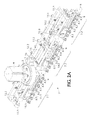
- FIG. 2 a is a first side perspective view of the on-load tap changer according to FIG. 1 , at which the selector contacts are arranged;
- FIG. 2 b is a second side perspective view of the on-load tap changer according to FIG. 1 , at which the switching means for the uninterrupted load changeover are arranged;
- FIG. 3 is a detail view of the guide rods of an on-load tap changer according to the invention.
- FIG. 4 a is a further detail view of the selector contact unit of an on-load tap changer according to the invention.
- FIG. 4 b is yet a further detail view of the selector contact unit of an on-load tap changer according to the invention.
- FIG. 5 shows a contact strip of an on-load tap changer according to the invention
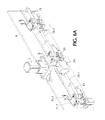
- FIG. 6 a is a side perspective view of a further form of embodiment of an on-load tap changer according to the invention.
- FIG. 6 b is a detail view of the side perspective view according to FIG. 6 a;
- FIG. 7 a is a first side perspective view of yet a further form of embodiment of an on-load tap changer according to the invention.
- FIG. 7 b is a second side perspective view of the further form of embodiment according to FIG. 7 a.
- FIG. 1 An on-load tap changer 1 according to the invention that is arranged directly below a transformer cover 2 of a tapped transformer (not illustrated in more detail), is shown in FIG. 1 in a perspective view.
- a more precise description of the components of the on-load tap changer 1 and the function thereof can be inferred from the description of the figures further below.
- a tapped transformer of that kind which is well-known from the prior art, comprises a transformer vessel that is filled with insulating oil and in which at least one winding is arranged at an iron yoke. This winding is divided into a main winding and a regulating winding, at which a plurality of winding taps forming the regulating range is provided.
- the on-load tap changer comprises a transmission module 3 that is attached to the underside of the transformer cover 2 and that cooperates with a motor drive 4 arranged at the opposite, outer side of the transformer cover 2 .
- the motor drive 4 can in that case be constructed as, for example, a proprietary step motor.
- the transmission module 3 comprises a flange-like sealing module 5 that is arranged directly at the underside of the transformer cover 2 and detachably connected, in particular screw-connected, with the motor drive 4 .
- the entire on-load tap changer 1 is thus fastened to the transmission module 3 .
- the transmission module 3 fulfils not only the task of mounting the on-load tap changer 1 , but also the task of hermetically sealing relative to the outer side of the transformer by means of the sealing module 5 . Consequently, twistings of the transformer cover 2 during transport of the transformer are not transmitted to the on-load tap changer 1 .
- FIGS. 2 a and 2 b show the on-load tap changer 1 according to the invention in two different perspective side views.
- Mechanically connected with the transmission module 3 is a support plate 6 of dielectric material, to which the individual subassemblies of the on-load tap changer 1 are fastenable.
- the support plate 6 is in that case made from electrically insulating material and constructed for the purpose of holding all significant components of the on-load tap changer 1 .
- FIG. 2 a shows the first side of the on-load tap changer 1 , at which the subassemblies of the at least selector contact unit 7 . 1 , 7 . 2 and 7 . 3 are fastened to the support plate 6 .
- FIG. 1 shows the first side of the on-load tap changer 1 , at which the subassemblies of the at least selector contact unit 7 . 1 , 7 . 2 and 7 . 3 are fastened to the support plate 6 .
- FIG. 1 shows the first side of the on-load tap changer 1 ,
- each selector contact unit 7 . 1 , 7 . 2 and 7 . 3 there are, for example, three selector contact units 7 . 1 , 7 . 2 and 7 . 3 ; each selector contact unit 7 . 1 , 7 . 2 and 7 . 3 is in that case connected with a separate phase, thus winding, of the tapped transformer.
- Each selector contact unit 7 . 1 . . . 7 . 3 comprises a respective plurality of connectable fixed selector contacts 8 . 1 . . . 8 . 5 that are electrically connected with the winding taps of the regulating winding of the tapped transformer, a contact rail 9 connected with a load diverter LA, and a contact carrier 10 . 1 . . . 10 . 3 with two respective resiliently mounted, movable selector contacts 11 .
- the contact carrier 10 . 1 . . . 10 . 3 of each phase is then mechanically fixed to a slide carriage 12 . 1 . . . 12 . 3 and forms together therewith a constructional unit.
- the slide carriages 12 . 1 . . . 12 . 3 are received at two parallel arranged guide rods 14 . 1 and 14 . 2 that are fixed to the support plate 6 by means of a plurality of cross members 13 . 1 . . . 13 .X, in such a manner that the individual fixed selector contacts 8 . 1 . .
- . 8 . 5 are connectable by a longitudinal displacement of the movable contacts 11 . 1 . . . 11 . 3 inclusive of slide carriages 12 . 1 . . . 12 . 3 along the guide rods 14 . 1 and 14 . 2 .
- a rotational movement produced by the motor drive 4 is transmitted by means of the transmission module 3 to a threaded spindle 15 disposed in engagement with a spindle nut 16 that is provided at the middle slide carriage 12 . 2 , so that a longitudinal displacement of the middle slide carriage 12 . 2 along the guide rods 14 . 1 and 14 . 2 can thus be produced.
- the remaining slide carriages 12 . 1 and 12 . 3 are in operative connection with the middle slide carriage 12 .
- the plurality of cross members 13 . 1 . . . 13 . 3 at which the guide rods 14 . 1 and 14 . 2 are retained, additionally forms a mechanical abutment for the movable contacts 10 . 1 . . . 10 . 3 that are longitudinally displaceable inclusive of slide carriages 12 . 1 . . . 12 . 3 , so that the regulating range of the on-load tap changer 1 is thus also mechanically limited.
- FIG. 2 b in that case shows the second side of the support plate 6 , at which the switching means for uninterrupted switching are arranged.
- the switching means for the uninterrupted switching are vacuum interrupters 19 . 1 . . . 19 . 6 , wherein in each instance two respective vacuum interrupters 19 . 1 and 19 . 2 or 19 . 3 and 19 . 4 or 19 . 5 and 19 . 6 are associated with each phase of the on-load tap changer 1 and cooperate with a corresponding selector contact unit 7 . 1 . . . 7 . 3 .
- the vacuum interrupters 19 . 1 . . . 19 . 6 are switching means, which are known from the prior art, with a movable switch contact 20 . 1 . .
- Each of the vacuum interrupters 19 . 1 . . . 19 . 6 in that regard comprises a movable switch contact 20 . 1 . . . 20 . 6 that is arranged at the second side of the support plate 6 to be respectively pivotably connected with a coupling element 21 . 1 . . . 21 . 6 and a control lever 22 . 1 . . . 22 . 6 . Provided at the pivotable connection between the corresponding coupling element 21 . 1 . . . 21 . 6 and the control lever 22 . 1 . . . 22 .
- the upper side 24 of the guide link 17 has in that case a profiling in the form of lobes so that the vacuum interrupters 19 . 1 . . . 19 . 6 can be connected, i.e. opened or closed, by a longitudinal displacement of the guide link 17 in dependence on the profiling of the upper side 24 of the guide link 17 .
- FIG. 3 shows a simplified detail view of the mechanical coupling of the slide carriages 12 . 1 . . . 12 . 3 with the guide link 17 .
- the transmission module 3 is shown that transmits rotational movement by way of gears (not illustrated here in more detail) to the threaded spindle 15 that in turn passes on the rotational movement to a spindle nut 16 provided in the middle slide carriage 12 . 2 , so that the rotational movement of the threaded spindle 15 is converted into a longitudinal movement of the middle slide carriage 12 . 2 along the guide rods 14 . 1 and 14 . 2 . Due to the fact that the slide carriages 12 . 1 . . . 12 .
- FIGS. 4 a and 4 b show, in two different perspectives, a further detail view of the selector contact unit 7 . 1 of a phase of the on-load tap changer 1 according to the invention and explain this by way of example; the selector contact units 7 . 2 and 7 . 3 are of identical construction. The following explanations therefore also apply to these selector contact units 7 . 2 and 7 . 3 .
- the fixed selector contacts 8 . 1 . . . 8 . 5 are in that case arranged at a contact strip 25 . 1 of plastics material, for example by means of a screw connection as illustrated here.
- the contact strip 25 . 1 is fastened to the support plate 6 by means of two respective spacers 27 . 1 and 27 .
- the contact strip 25 . 1 has at the longitudinal side thereof a control link 26 . 1 at which several lobes 28 . 1 . . . 28 . 4 are arranged on both sides in order to vertically move the resiliently mounted selector contacts 11 . 1 and 11 . 2 of the corresponding selector contact unit 7 . 1 in the case of longitudinal displacement of the corresponding slide carriage 12 . 1 , by means of the lobes 28 . 1 . . . 28 . 4 provided at the control link 26 . 1 , in dependence on the profile of the plurality of lobes 28 . 1 . . . 28 . 4 .
- the profile of the lobes 28 . 1 . . . 28 . 4 is in that case dimensioned so that the movable selector contacts 11 . 1 , 11 . 2 of the selector contact unit 7 . 1 lift off the currently connected fixed selector contact, here 8 . 1 , between two adjacent fixed selector contacts 8 . 1 . . . 8 . 5 , since after switching-over is completed they connect again the next fixed selector contact, here 8 . 2 .
- a middle setting of the movable selector contacts 11 . 1 and 11 . 2 at two adjacent fixed selector contacts 8 . 1 . . . 8 . 5 is permissible according to the reactor switching principle.
- the contact members 11 . 1 and 11 . 2 are formed to be spherical at the actual contact surface.
- FIG. 5 shows the contact strip 25 . 1 . . . 25 . 3 with the control link 26 . 1 . . . 26 . 3 and the respective plurality of lobes 28 . 1 . . . 28 . 4 in a detail illustration, by means of which the corresponding movable selector contacts 11 . 1 and 11 . 2 or 11 . 3 and 11 . 4 or 11 . 5 and 11 . 6 of each selector contact unit 7 . 1 . . . 7 . 3 are vertically displaced during a switching-over process depending on the profiling of the lobes 28 . 1 . . . 28 . 4 .
- the movable switch contacts 20 . 1 . . . 20 . 6 of the vacuum interrupters 19 . 1 . . . 19 . 6 are electrically connected with the spacers 27 . 1 . . . 27 . 2 associated with the respective phase and thus ultimately with the corresponding switch-over chokes, whereas the corresponding fixed contacts 18 . 1 . . . 18 . 6 of the corresponding vacuum interrupters 19 . 1 . . . 19 . 6 are electrically connected with the contact rail 9 of the associated phase.
- FIGS. 6 a and 6 b A further form of embodiment of an on-load tap changer 1 according to the invention is shown in FIGS. 6 a and 6 b .
- the switching means for uninterrupted switching thus the vacuum interrupters 19 . 1 . . . 19 . 6 , are arranged directly at the corresponding slide carriage 12 . 1 . . . 12 . 3 of the respective selector contact unit 7 . 1 . . . 7 . 3 and constructed to be movable therewith along the threaded spindle 15 .
- each selector contact unit 7 . 1 . . . 7 . 3 has its own spindle nut 16 —not visible in this illustration—arranged in the corresponding slide carriage 12 . 1 . . . 12 . 3 , so that the selector contact units 7 . 1 . . . 7 . 3 are thus constructed to be synchronously displaceable along the insulating shaft 15 .
- the insulating shaft 15 is composed of a plurality of elements and has in each instance between the corresponding elements a coupling tube 28 . 1 . . . 28 . 2 formed from electrically insulating material.
- an angle transmission 29 is provided in order to pass on the rotational movement of the motor drive 3 to the threaded spindle 15 .
- the fixed contacts 18 . 1 . . . 18 . 6 of the vacuum interrupters 19 . 1 . . . 19 . 6 arranged at the corresponding slide carriage 12 . 1 . . . 12 . 3 are screw-connected with the support plate 6 by means of respective wires 31 . 1 . . . 31 . 6 and electrically connected with switch-over chokes (not illustrated).
- the fixed selector contacts 8 . 1 . . . 8 . 5 are here arranged directly on the support plate 6 and electrically connected on the opposite side (not illustrated here) of the support plate 6 with the corresponding winding taps of the regulating winding of the tapped transformer.
- FIGS. 7 a and 7 b Yet a further form of embodiment of an on-load tap changer 1 according to the invention is shown in FIGS. 7 a and 7 b .
- the motor drive 3 there is driven by the motor drive 3 not only a threaded spindle 15 that is in turn in mechanically operative connection with each of the selector contact units 7 . 1 . . . 7 . 3 , but also a camshaft 35 , by way of which the switching means for uninterrupted switching, thus the vacuum interrupters 19 . 1 . . . 19 .
- the threaded spindle 15 is here constructed as a threaded spindle over its entire length and is in engagement with the spindle nut 16 that is provided in each of the slide carriages 12 . 1 . . . 12 . 3 , in such a manner that each slide carriage 12 . 1 . . . 12 . 3 is horizontally moved when rotation of the threaded spindle 15 takes place.
- the other selector contact unit 7 . 1 . . . 7 . 3 is of identical construction to the selector contact unit 7 . 1 . . . 7 . 3 described in FIGS. 1 to 5 .
- each movable switch contact 20 . 1 . . . 20 . 6 is mechanically constrainedly coupled with a stroke rod 36 . 1 . . . 36 . 6 that so cooperates with cam lobes 37 . 1 . . . 37 . 6 that are opposite the movable switch contacts 20 . 1 . . . 20 . 6 and arranged on the camshaft 35 , that when rotation of the camshaft 35 takes place the cam lobe 37 . 1 . . . 37 . 6 introduces a vertical movement into the corresponding stroke rod 36 . 1 . . . 36 .
- the on-load tap changer 1 according to the invention is usable not only in accordance with the reactor switching principle, but also in accordance with the resistance fast switching principle.
- nine stationary operational settings are permissible with the, here, five illustrated fixed selector contacts 8 . 1 . . . 8 . 5 in accordance with the reactor switching principle, whereas merely five stationary operational settings are permissible with an on-load tap changer 1 according to the invention constructed in accordance with the resistance fast switching principle.
Landscapes
- Engineering & Computer Science (AREA)
- Power Engineering (AREA)
- Housings And Mounting Of Transformers (AREA)
- High-Tension Arc-Extinguishing Switches Without Spraying Means (AREA)
- Slide Switches (AREA)
- Driving Mechanisms And Operating Circuits Of Arc-Extinguishing High-Tension Switches (AREA)
- Rotary Switch, Piano Key Switch, And Lever Switch (AREA)
Applications Claiming Priority (4)
| Application Number | Priority Date | Filing Date | Title |
|---|---|---|---|
| DE202012101477U DE202012101477U1 (de) | 2012-04-20 | 2012-04-20 | Laststufenschalter |
| DE202012101477.7 | 2012-04-20 | ||
| DE202012101477U | 2012-04-20 | ||
| PCT/EP2013/056264 WO2013156265A1 (de) | 2012-04-20 | 2013-03-25 | Laststufenschalter |
Publications (2)
| Publication Number | Publication Date |
|---|---|
| US20150091684A1 US20150091684A1 (en) | 2015-04-02 |
| US9762161B2 true US9762161B2 (en) | 2017-09-12 |
Family
ID=48013973
Family Applications (1)
| Application Number | Title | Priority Date | Filing Date |
|---|---|---|---|
| US14/382,327 Expired - Fee Related US9762161B2 (en) | 2012-04-20 | 2013-03-25 | On-load tap changer |
Country Status (9)
| Country | Link |
|---|---|
| US (1) | US9762161B2 (de) |
| EP (1) | EP2839492B1 (de) |
| JP (1) | JP6373254B2 (de) |
| KR (1) | KR20150003843A (de) |
| CN (1) | CN104246949B (de) |
| DE (1) | DE202012101477U1 (de) |
| RU (1) | RU2621070C2 (de) |
| UA (1) | UA116201C2 (de) |
| WO (1) | WO2013156265A1 (de) |
Cited By (1)
| Publication number | Priority date | Publication date | Assignee | Title |
|---|---|---|---|---|
| US20200411254A1 (en) * | 2018-03-06 | 2020-12-31 | Maschinenfabrik Reinhausen Gmbh | On-load tap changer and local network transformer having an on-load tap changer |
Families Citing this family (14)
| Publication number | Priority date | Publication date | Assignee | Title |
|---|---|---|---|---|
| EP2797088A1 (de) * | 2013-04-23 | 2014-10-29 | ABB Technology AG | Spule für einen Trockentransformator und Trockentransformator |
| CN105580100B (zh) * | 2013-08-27 | 2017-12-12 | 赖茵豪森机械制造公司 | 有载分接开关、用于电压调节的可调式变压器和用于在可调式变压器中实施转换的方法 |
| CN104810168B (zh) * | 2015-03-10 | 2017-04-26 | 上海华明电力设备制造有限公司 | 电抗式真空条形有载分接开关 |
| DE102016104500B3 (de) * | 2016-03-11 | 2017-05-04 | Maschinenfabrik Reinhausen Gmbh | Laststufenschalter |
| CN105957740B (zh) * | 2016-07-15 | 2019-04-16 | 武汉泰普联合分接开关股份有限公司 | 一种带隔离板的无励磁分接开关 |
| CN106653426B (zh) * | 2017-01-12 | 2018-08-17 | 济南爱迪电气设备有限公司 | 一种配电变压器专用有载调压开关 |
| CN106952756B (zh) * | 2017-03-21 | 2018-07-10 | 黄河科技学院 | 一种分接开关的机电一体化装置 |
| CN107293423B (zh) * | 2017-03-31 | 2020-07-24 | 宁波安德奥电力设备有限公司 | 直线式真空有载双档位切换开关 |
| CN107039195B (zh) * | 2017-03-31 | 2020-04-21 | 宁波安德奥电力设备有限公司 | 直线式永磁真空有载分接开关 |
| CN109449018B (zh) * | 2018-12-23 | 2023-11-07 | 辽宁金立电力电器有限公司 | 一种有载分接开关 |
| DE102020122450A1 (de) * | 2020-08-27 | 2022-03-03 | Maschinenfabrik Reinhausen Gmbh | Schaltmodul und Laststufenschalter mit Schaltmodul |
| DE102020122453A1 (de) | 2020-08-27 | 2022-03-03 | Maschinenfabrik Reinhausen Gmbh | Laststufenschaltermodul |
| KR102401801B1 (ko) * | 2020-09-07 | 2022-05-25 | (주) 모노인더스트리 | 자동 제어 무부하 탭 절환기 |
| CN115922669A (zh) * | 2022-10-31 | 2023-04-07 | 达闼机器人股份有限公司 | 防绕线限位检测装置及升降旋转机构 |
Citations (9)
| Publication number | Priority date | Publication date | Assignee | Title |
|---|---|---|---|---|
| US3138671A (en) * | 1959-01-07 | 1964-06-23 | Lepper Wilhelm | On-load transformer tap changer |
| US4234864A (en) | 1978-06-16 | 1980-11-18 | Asea Aktiebolag | Transformer with offset side wall-mounted on-load tap changer |
| JPS59204224A (ja) | 1983-05-07 | 1984-11-19 | Hokuriku Denki Seizo Kk | 負荷時タツプ切換器の真空バルブ操作機構 |
| US5523674A (en) * | 1992-07-16 | 1996-06-04 | Maschinenfabrik Reinhausen Gmbh | Step switch |
| DE19847745C1 (de) | 1998-10-16 | 2000-01-05 | Reinhausen Maschf Scheubeck | Stufenschalter |
| US7145760B2 (en) | 2000-12-15 | 2006-12-05 | Abb Technology Ltd. | Tap changer monitoring |
| WO2011012181A1 (de) * | 2009-07-30 | 2011-02-03 | Maschinenfabrik Reinhausen Gmbh | Anordnung eines stufenschalters an einem regeltransformator |
| US20120139510A1 (en) | 2009-09-26 | 2012-06-07 | Silke Wrede | Tap changer with vacuum switch tubes |
| US20130213777A1 (en) | 2010-08-18 | 2013-08-22 | Dieter Dohnal | Tap changer |
Family Cites Families (15)
| Publication number | Priority date | Publication date | Assignee | Title |
|---|---|---|---|---|
| JPS5943708Y2 (ja) * | 1980-01-24 | 1984-12-26 | 株式会社東芝 | タップ切換器 |
| JPS57170531U (de) * | 1981-04-22 | 1982-10-27 | ||
| JPS62274611A (ja) * | 1986-05-22 | 1987-11-28 | Toshiba Corp | 負荷時タツプ切換器 |
| DE4237242A1 (de) * | 1992-05-15 | 1994-05-05 | Reinhausen Maschf Scheubeck | Stufenschalter für einen vorzugsweise gießharzisolierten Stufentransformator |
| DE4237165C1 (de) | 1992-11-04 | 1994-03-17 | Reinhausen Maschf Scheubeck | Einpoliger Stufenschalter mit linearer Kontaktbetätigung für einen Stufentransformator |
| CN1037040C (zh) * | 1993-05-06 | 1998-01-14 | 赖茵豪森机械制造公司 | 直接接触式单极分接开关 |
| JP4034392B2 (ja) * | 1997-11-26 | 2008-01-16 | 東芝変電機器テクノロジー株式会社 | タップ選択器 |
| DE19836463C1 (de) * | 1998-08-12 | 1999-10-21 | Reinhausen Maschf Scheubeck | Stufenschalter mit einem Vorwähler |
| JP4201963B2 (ja) * | 2000-08-03 | 2008-12-24 | 株式会社東芝 | 負荷時タップ切換器の真空バルブ開閉機構 |
| MXPA05010395A (es) * | 2003-04-03 | 2005-11-08 | Reinhausen Maschf Scheubeck | Conmutador selector. |
| JP4649448B2 (ja) * | 2007-06-22 | 2011-03-09 | 有限会社田島製作所 | 無電圧タップ切換器 |
| RU69680U1 (ru) * | 2007-07-23 | 2007-12-27 | Федеральное Гоударственное предприятие "Научно-производственное предприятие "Торий" | Лампа бегущей волны с магнитной периодической фокусирующей системой |
| GB2457079A (en) * | 2008-02-01 | 2009-08-05 | Brush Transformers Ltd | On-load tap changer |
| JP2011054835A (ja) * | 2009-09-03 | 2011-03-17 | Toshiba Corp | 負荷時タップ切換装置の切換開閉器 |
| DE102010008973B4 (de) * | 2010-02-24 | 2015-11-05 | Maschinenfabrik Reinhausen Gmbh | Stufenschalter des Hybridtyps mit Halbleiterschaltelementen |
-
2012
- 2012-04-20 DE DE202012101477U patent/DE202012101477U1/de not_active Expired - Lifetime
-
2013
- 2013-03-25 CN CN201380020450.0A patent/CN104246949B/zh not_active Expired - Fee Related
- 2013-03-25 EP EP13712753.6A patent/EP2839492B1/de not_active Not-in-force
- 2013-03-25 JP JP2015506156A patent/JP6373254B2/ja not_active Expired - Fee Related
- 2013-03-25 KR KR20147032472A patent/KR20150003843A/ko not_active Withdrawn
- 2013-03-25 WO PCT/EP2013/056264 patent/WO2013156265A1/de not_active Ceased
- 2013-03-25 US US14/382,327 patent/US9762161B2/en not_active Expired - Fee Related
- 2013-03-25 UA UAA201411443A patent/UA116201C2/uk unknown
- 2013-03-25 RU RU2014146592A patent/RU2621070C2/ru not_active IP Right Cessation
Patent Citations (10)
| Publication number | Priority date | Publication date | Assignee | Title |
|---|---|---|---|---|
| US3138671A (en) * | 1959-01-07 | 1964-06-23 | Lepper Wilhelm | On-load transformer tap changer |
| US4234864A (en) | 1978-06-16 | 1980-11-18 | Asea Aktiebolag | Transformer with offset side wall-mounted on-load tap changer |
| JPS59204224A (ja) | 1983-05-07 | 1984-11-19 | Hokuriku Denki Seizo Kk | 負荷時タツプ切換器の真空バルブ操作機構 |
| US5523674A (en) * | 1992-07-16 | 1996-06-04 | Maschinenfabrik Reinhausen Gmbh | Step switch |
| DE19847745C1 (de) | 1998-10-16 | 2000-01-05 | Reinhausen Maschf Scheubeck | Stufenschalter |
| US7145760B2 (en) | 2000-12-15 | 2006-12-05 | Abb Technology Ltd. | Tap changer monitoring |
| WO2011012181A1 (de) * | 2009-07-30 | 2011-02-03 | Maschinenfabrik Reinhausen Gmbh | Anordnung eines stufenschalters an einem regeltransformator |
| US8648587B2 (en) | 2009-07-30 | 2014-02-11 | Maschinenfabrik Reinhausen Gmbh | Arrangement of a stepping switch on a control transformer |
| US20120139510A1 (en) | 2009-09-26 | 2012-06-07 | Silke Wrede | Tap changer with vacuum switch tubes |
| US20130213777A1 (en) | 2010-08-18 | 2013-08-22 | Dieter Dohnal | Tap changer |
Non-Patent Citations (2)
| Title |
|---|
| Machine translation DE19847745 (orig. doc published Jan. 5, 2000). * |
| Machine translation WO2011012181 (orig. doc. published Feb. 2011). * |
Cited By (2)
| Publication number | Priority date | Publication date | Assignee | Title |
|---|---|---|---|---|
| US20200411254A1 (en) * | 2018-03-06 | 2020-12-31 | Maschinenfabrik Reinhausen Gmbh | On-load tap changer and local network transformer having an on-load tap changer |
| US11631554B2 (en) * | 2018-03-06 | 2023-04-18 | Maschinenfabrik Reinhausen Gmbh | On-load tap changer and local network transformer having an on-load tap changer |
Also Published As
| Publication number | Publication date |
|---|---|
| JP2015517219A (ja) | 2015-06-18 |
| JP6373254B2 (ja) | 2018-08-15 |
| EP2839492A1 (de) | 2015-02-25 |
| CN104246949B (zh) | 2017-05-31 |
| RU2621070C2 (ru) | 2017-05-31 |
| CN104246949A (zh) | 2014-12-24 |
| UA116201C2 (uk) | 2018-02-26 |
| KR20150003843A (ko) | 2015-01-09 |
| DE202012101477U1 (de) | 2013-07-23 |
| RU2014146592A (ru) | 2016-06-10 |
| HK1202982A1 (en) | 2015-10-09 |
| WO2013156265A1 (de) | 2013-10-24 |
| EP2839492B1 (de) | 2016-11-16 |
| US20150091684A1 (en) | 2015-04-02 |
Similar Documents
| Publication | Publication Date | Title |
|---|---|---|
| US20150091684A1 (en) | On-load tap changer | |
| US9543096B2 (en) | On-load tap changer | |
| US20150034462A1 (en) | On-load tap changer | |
| US9406434B2 (en) | Distribution transformer for voltage regulation of local distribution networks | |
| US9455658B2 (en) | On-load tap changer | |
| US20150303006A1 (en) | On-load tap changer | |
| KR20220098748A (ko) | 온-부하 탭-절환기 및 온-부하 탭-절환기를 가지는 탭-절환 변압기 | |
| HK1202982B (en) | On-load tap changer | |
| HK1202981B (en) | On-load tap changer | |
| HK1202977B (en) | On-load tap changer | |
| HK1202979B (en) | On-load tap changer | |
| HK1207737B (en) | On-load tap changer |
Legal Events
| Date | Code | Title | Description |
|---|---|---|---|
| AS | Assignment |
Owner name: MASCHINENFABRIK REINHAUSEN GMBH, GERMANY Free format text: ASSIGNMENT OF ASSIGNORS INTEREST;ASSIGNORS:PANKOFER, MARTIN;STOCKER, ANDREAS;SIGNING DATES FROM 20140902 TO 20140908;REEL/FRAME:033816/0105 |
|
| STCF | Information on status: patent grant |
Free format text: PATENTED CASE |
|
| FEPP | Fee payment procedure |
Free format text: MAINTENANCE FEE REMINDER MAILED (ORIGINAL EVENT CODE: REM.); ENTITY STATUS OF PATENT OWNER: LARGE ENTITY |
|
| LAPS | Lapse for failure to pay maintenance fees |
Free format text: PATENT EXPIRED FOR FAILURE TO PAY MAINTENANCE FEES (ORIGINAL EVENT CODE: EXP.); ENTITY STATUS OF PATENT OWNER: LARGE ENTITY |
|
| STCH | Information on status: patent discontinuation |
Free format text: PATENT EXPIRED DUE TO NONPAYMENT OF MAINTENANCE FEES UNDER 37 CFR 1.362 |
|
| FP | Lapsed due to failure to pay maintenance fee |
Effective date: 20210912 |