US9751164B2 - Method of manufacturing a hollow poppet valve - Google Patents
Method of manufacturing a hollow poppet valve Download PDFInfo
- Publication number
- US9751164B2 US9751164B2 US15/035,955 US201315035955A US9751164B2 US 9751164 B2 US9751164 B2 US 9751164B2 US 201315035955 A US201315035955 A US 201315035955A US 9751164 B2 US9751164 B2 US 9751164B2
- Authority
- US
- United States
- Prior art keywords
- coolant
- rod
- cavity
- valve
- hole
- Prior art date
- Legal status (The legal status is an assumption and is not a legal conclusion. Google has not performed a legal analysis and makes no representation as to the accuracy of the status listed.)
- Expired - Fee Related
Links
Images


Classifications
-
- B—PERFORMING OPERATIONS; TRANSPORTING
- B21—MECHANICAL METAL-WORKING WITHOUT ESSENTIALLY REMOVING MATERIAL; PUNCHING METAL
- B21K—MAKING FORGED OR PRESSED METAL PRODUCTS, e.g. HORSE-SHOES, RIVETS, BOLTS OR WHEELS
- B21K1/00—Making machine elements
- B21K1/20—Making machine elements valve parts
- B21K1/22—Making machine elements valve parts poppet valves, e.g. for internal-combustion engines
-
- B—PERFORMING OPERATIONS; TRANSPORTING
- B23—MACHINE TOOLS; METAL-WORKING NOT OTHERWISE PROVIDED FOR
- B23P—METAL-WORKING NOT OTHERWISE PROVIDED FOR; COMBINED OPERATIONS; UNIVERSAL MACHINE TOOLS
- B23P15/00—Making specific metal objects by operations not covered by a single other subclass or a group in this subclass
- B23P15/001—Making specific metal objects by operations not covered by a single other subclass or a group in this subclass valves or valve housings
- B23P15/002—Making specific metal objects by operations not covered by a single other subclass or a group in this subclass valves or valve housings poppet valves
-
- F—MECHANICAL ENGINEERING; LIGHTING; HEATING; WEAPONS; BLASTING
- F01—MACHINES OR ENGINES IN GENERAL; ENGINE PLANTS IN GENERAL; STEAM ENGINES
- F01L—CYCLICALLY OPERATING VALVES FOR MACHINES OR ENGINES
- F01L3/00—Lift-valve, i.e. cut-off apparatus with closure members having at least a component of their opening and closing motion perpendicular to the closing faces; Parts or accessories thereof
- F01L3/12—Cooling of valves
- F01L3/14—Cooling of valves by means of a liquid or solid coolant, e.g. sodium, in a closed chamber in a valve
-
- F—MECHANICAL ENGINEERING; LIGHTING; HEATING; WEAPONS; BLASTING
- F01—MACHINES OR ENGINES IN GENERAL; ENGINE PLANTS IN GENERAL; STEAM ENGINES
- F01L—CYCLICALLY OPERATING VALVES FOR MACHINES OR ENGINES
- F01L3/00—Lift-valve, i.e. cut-off apparatus with closure members having at least a component of their opening and closing motion perpendicular to the closing faces; Parts or accessories thereof
- F01L3/08—Valves guides; Sealing of valve stem, e.g. sealing by lubricant
-
- Y—GENERAL TAGGING OF NEW TECHNOLOGICAL DEVELOPMENTS; GENERAL TAGGING OF CROSS-SECTIONAL TECHNOLOGIES SPANNING OVER SEVERAL SECTIONS OF THE IPC; TECHNICAL SUBJECTS COVERED BY FORMER USPC CROSS-REFERENCE ART COLLECTIONS [XRACs] AND DIGESTS
- Y10—TECHNICAL SUBJECTS COVERED BY FORMER USPC
- Y10T—TECHNICAL SUBJECTS COVERED BY FORMER US CLASSIFICATION
- Y10T29/00—Metal working
- Y10T29/49—Method of mechanical manufacture
- Y10T29/49229—Prime mover or fluid pump making
- Y10T29/49298—Poppet or I.C. engine valve or valve seat making
Definitions
- This invention relates to a method of manufacturing a hollow poppet valve having an internal cavity that extends from within a valve head into a stem portion of the valve and is filled with a coolant.
- a hollow poppet valve having a valve head and a stem portion integral therewith and formed with an internal cavity that extends from within the valve head into the stem portion, the cavity being charged, together with an inner gas, with a coolant that has a higher heat conductivity than the valve material.
- a coolant that has a higher heat conductivity than the valve material.
- An example of such coolant is metallic sodium which has a melting point of about 98° C.
- this valve has an internal cavity extending from within the valve head into the stem portion, and hence larger than a conventional internal cavity formed only in a stem portion, the valve can contain a larger volume of coolant in the internal cavity than the conventional valve and provide an enhanced heat transferability (hereinafter referred to as heat reduction capability).
- heat reduction capability an enhanced heat transferability
- the valve when it has a diametrically larger internal cavity in the valve head than a diametrically small internal cavity in the stem portion, it can be charged with a still larger volume of coolant in the valve to increase its heat reduction capability.
- Patents Documents 1 and 2 listed below disclose methods of manufacturing hollow poppet valves in which metallic sodium is injected from a nozzle into an internal cavity of the valve placed below the nozzle.
- Patent Document 2 discloses a step of injecting pressurized clayish metallic sodium extruded from a nozzle of an extruder into a cavity of a valve below the nozzle while cooling the metallic sodium.
- Patent Document 1 JPA Laid Open H3-18605
- Patent Document 2 JPA Laid Open H4-232318
- Patent Document 1 Although the method of Patent Document 1 enables injection of a large amount of coolant into an internal cavity of a valve, it is necessary to maintain the metallic sodium in molten state in a container. Further, in order to prevent the injected metallic sodium from being cooled, solidified, and stacked during injection as the coolant comes into contact with the valve, it is necessary to control the temperature of the facility in use, which increases manufacturing cost of the valve.
- a clayish solidified elongate metallic sodium is extruded from a nozzle and injected into an internal cavity of a valve, but smooth injection of such elongate coolant may be impeded by an interfering inner periphery of the internal cavity before the coolant reaches a deep level in the internal cavity.
- the clayish metallic sodium extruded from the nozzle has a length that corresponds to the depth of the internal cavity (which is much larger than its thickness), it is often bent before it is smoothly injected deeply into the cavity.
- the inventors have come across a desirable solution to increase the amount of metallic sodium extruded from an extruder and inserted into an internal cavity as much as possible by first reducing the interference between the outer periphery of the elongate coolant and the inner periphery of the internal cavity by approximating the outer diameter of the elongate coolant to the inner diameter of the cavity so as to permit smooth insertion of the elongate coolant. To do this, the elongate metallic sodium to be inserted is shortened to prevent its bending (or enhancing its linearity).
- a method of manufacturing a hollow poppet valve having an internal cavity that extends from within a valve head into a stem portion of the hollow poppet valve and is filled with a coolant comprising:
- a coolant-rod forming step for extruding from a nozzle of an extruder a linear clayish coolant and cutting the linear coolant into coolant rods of a predetermined length;
- a coolant-rod inserting step for inserting the coolant rod into a hole of an intermediate valve product that corresponds to the internal cavity of the hollow poppet valve, through an open end of the hole;
- the method characterized in that the coolant rod is divided into multiple pieces for insertion into the hole in multiple times in the coolant-rod injection step.
- the length of each coolant rod to be injected into the hole is about one half the length of a coolant rod to be inserted in one step.
- each coolant rod is short, the rod is less likely to be bent and interfere with the inner periphery of the hole of the intermediate valve product during insertion. Consequently, by approximating the outer diameter of the coolant rod to the inner diameter of the hole (or the internal cavity), gaps between the inserted coolant rod and the inner periphery of the hole can be reduced and accordingly the volume of the coolant in the hole can be increased.
- the method may comprise a further step of pressurizing the coolant rod inserted in the hole of the intermediate valve product with a pushing rod.
- the coolant-rod insertion step can be adapted to determine existence of the coolant-rod in the hole and propriety in length thereof on the basis of a length of the pushing bar inserted into the hole.
- the pushing rod used to pressurize the inserted coolant-rod in the hole of the intermediate valve product functions to deform them plastically in abutment against the inner periphery of the hole, so that the length of the pushing rod inserted into the hole can indicate if the coolant rod is correctly inserted in the hole, thereby detecting if the coolant rod has a correct length.
- the length of the pushing rod inserted into the hole should be constant if coolant rod has a proper length when inserted in the cavity of an intermediate valve product. On the other hand, in a case where no coolant rod is inserted in the hole for some reason or their length is either too short or too long, the downward travel distance of the pushing rod is not in a predetermined range.
- the coolant-rod forming step is adapted to
- the cut coolant-rod is instantly placed in the cylindrical jig immediately after it is cut by the cutter, it may be transferred to a station for the coolant-rod insertion step without being deformed, in spite of the fact that otherwise the metallic sodium rod can be easily deformed, that is, if it is brought into contact with anything other than a coolant rod.
- the coolant-rod transferred to a station for the coolant-rod insertion step still maintains its straight configuration and its cut end undeformed, so that it can be smoothly inserted into the hole of an intermediate valve product, without interfering with the inner periphery of the hole (or cavity).
- the coolant rod is stored in the jig while it is transferred to a station for the coolant-rod insertion step, where the rod is arranged above, and in opposition to, an upper end of the hole of the intermediate valve product and ejected from the jig for insertion into the hole by a gas pressure.
- the coolant rod in the jig Since the coolant rod in the jig is smoothly and instantly inserted into the hole of an intermediate valve product by the gas pressure, the coolant rod will be little exposed to an ambient air. It means that the coolant rod in the jig can be inserted into the hole in an extremely short period of time in the coolant-rod insertion step, which is a great advantage for the metallic sodium coolant that can be otherwise easily oxidized by the ambient air. It is preferred to use an inert gas as the pressurizing gas for pushing the coolant-rod into the hole.
- an inert gas in the manner as stated above is a positive way of suppressing oxidization of the coolant during a period between its extrusion from the nozzle of the extruder and insertion into the hole, and may prevent the surface of the coolant rod from becoming sticky and permit its smooth insertion into the hole.
- the method may be configured such that:
- the coolant-rod insertion step includes a process of inserting a coolant-rod from a bottom opening of a diametrically large internal cavity formed in the valve head shell in communication with a diametrically small internal cavity formed in the stem portion of the intermediate valve product, and
- the sealing step includes a process of welding a cap to the opening of the diametrically large internal cavity.
- a hollow poppet valve charged with a coolant can be manufactured by inserting a coolant rod into the internal cavity from the opening and then welding a cap to the opening to close the internal cavity.
- the coolant-rod insertion step may be adapted to insert a coolant rod from an open end of the diametrically small stem cavity in communication with the diametrically large internal cavity in the valve head shell; and the sealing step may be adapted to weld a stem end member to that end of the stem portion of the intermediate valve product.
- the diametrically small internal cavity of the intermediate valve product is communicated with the diametrically large internal cavity of the valve head shell and has an opening at an end remote from the in valve head shell, so that a hollow poppet valve charged with coolant in the internal cavity can be manufactured by welding the stem member to the opening of the stem cavity to seal the internal cavity after coolant rod is inserted from the open end.
- the present invention provides a hollow poppet valve having an excellent heat reduction effect by virtue of a large volume of coolant inserted into an internal cavity of an intermediate valve product in the coolant-rod insertion step.
- the inventive method may provide a hollow poppet valve having a still more excellent heat reduction effect, since the method enables insertion of a very large volume of coolant in the internal cavity of the valve by inserting such coolant into the hole of an intermediate valve product.
- the amount of coolant charged in the hole of the intermediate valve is directly controlled by a pushing rod, so that a resultant hollow poppet valve contains a well managed constant volume of coolant and has a constant quality.
- a coolant rod formed in the coolant-rod forming step is stowed in a jig without deforming the cut face and straight configuration of the rod until it is transferred to a station for the coolant-rod insertion step where the coolant rod needs to be inserted straight into a hole of an intermediate valve, the coolant-rod is allowed to be smoothly inserted in the hole in the coolant-rod insertion step, thereby rendering the coolant-rod insertion step smooth.
- the inventive method may provide provision of a hollow poppet valve having an excellent heat reduction effect in spite of the fact that the internal cavity is filled with a large volume of easily oxidizable coolant. This can be done by positively suppressing possible oxidization of the coolant over a period between its extrusion from an extruder and its insertion into an internal cavity of the intermediate valve product.
- a hollow poppet valve having an internal cavity filled with a large volume of coolant can be obtained from an intermediate valve product having an opening in the bottom of the internal cavity of the valve head shell by inserting a large volume of coolant into the internal cavity from the opening.
- a hollow poppet valve filled with a large volume of coolant in its internal cavity is obtained from an intermediate valve product having at one end of the stem portion a hole that corresponds to the internal cavity of the hollow poppet valve.
- FIG. 1 is a longitudinal cross section of a hollow poppet valve manufactured by a first method according to the invention.
- FIG. 2 shows in enlarged view movements of a coolant in the hollow poppet valve during reciprocal motions of the valve in its axial direction. More particularly, FIG. 2( a ) shows a movement of the coolant when a closed valve is opened, and FIG. 2( b ) when the open valve is closes.
- FIG. 3 shows steps of manufacturing a hollow poppet valve according to the present invention. More particularly, FIG. 3( a ) shows a drilling step in which a diametrically small cavity is bored in a bottom of a recess of a valve head shell, subsequent to a step of forming the valve head shell of an intermediate valve product; FIG. 3( b ) , a first coolant-rod forming and storing step, in which a coolant rod is cut off a coolant material extruded from a first extruder and is stored in a jig; FIG.
- FIG. 3( c ) a first coolant-rod insertion step for inserting the coolant rod into the diametrically small internal cavity of the intermediate valve product, through the recess of the valve head shell;
- FIG. 3( d ) a first coolant-rod pressuring step, in which the coolant rod in the diametrically small cavity is pressurized by a pushing rod;
- FIG. 3( e ) a second coolant-rod forming and storing step in which a second coolant rod is cut off the coolant material extruded from a second extruder, and is stored in a second jig;
- FIG. 3( f ) a second coolant rod insertion step in which a second coolant rod is inserted into a recess of the valve head shell of the intermediate valve product through an opening of the recess;
- FIG. 3( g ) a second coolant-rod pressurizing step in which the coolant rod in the recess (diametrically large cavity) is pressurized by a pushing rod;
- FIG. 3( h ) a sealing step in which a cap is welded to the opening of the recess (diametrically large cavity) of a valve head shell to seal the opening.
- FIG. 4 shows longitudinal cross sections of jigs for storing different coolant rods. More particularly, FIG. 4( a ) is a longitudinal cross section of a first jig for storing a first coolant rod; and FIG. 4( b ) a longitudinal cross section of a second jig for storing a second coolant rod.
- FIG. 5 is a longitudinal cross section of a lower guide portion of a jig.
- FIG. 6 is a bottom view of the lower guide portion.
- FIG. 7 is a longitudinal cross section of a hollow poppet valve manufactured by a second method according to the invention.
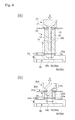
- FIG. 8 shows steps of manufacturing the hollow poppet valve shown in FIG. 7 . More particularly, FIG. 8( a ) shows a drilling step, subsequent to a step of forming a valve head shell at one end of a stem portion of the intermediate valve product, wherein the intermediate valve product is bored to form a hole (that corresponds to an internal cavity of a hollow poppet valve) extending from said one end of the stem portion into the valve head shell.
- FIG. 8( b ) a first-coolant-rod forming and storing step in which a first coolant rod is cut off a coolant material extruded from the first extruder and is stored in a jig; FIG.
- FIG. 8( c ) a first-coolant-rod insertion step in which a first coolant rod is inserted into the internal cavity of the intermediate valve product through an opening of the hole of the stem portion;
- FIG. 8( d ) a first-coolant-rod pressurizing step in which a first coolant rod in the internal cavity is pressurized with an pushing rod;
- FIG. 8( e ) a second-coolant-rod forming and storing step in which a second coolant rod is cut off the coolant material extruded from a second extruder and stored in a jig;
- FIG. 8( f ) a second-coolant-rod insertion step in which a second coolant rod is inserted into an internal cavity of the intermediate valve product through an opening of the hole of the stem portion of the intermediate valve product;
- FIG. 8( g ) a second-coolant-rod pressurizing step in which the second coolant rod in an internal cavity is pressurized with a pushing rod;
- FIG. 8( h ) a sealing step in which a stem member is welded to an open end of the stem portion of the intermediate valve product.
- FIG. 9 shows a longitudinal cross section of a hollow poppet valve manufactured by a third method according to the invention.
- FIG. 10 shows major processes of the third method. More particularly, FIG. 10( a ) shows a cross section of an intermediate valve product charged with a first coolant rod in its internal cavity in the first coolant-rod insertion step; and FIG. 10( b ) , a cross section of the intermediate valve product with the inserted first coolant rod in the internal cavity is pressurized with a pushing rod.
- FIG. 1 shows a hollow poppet valve manufactured by a method of a first embodiment according to the invention.
- FIG. 2 shows in enlarged view movements of a coolant in the internal cavity of a hollow poppet valve during reciprocal motions in the axial direction of the valve.
- a hollow poppet valve 10 made of a heat resisting metal, has a valve head 14 which has a valve seat face 16 formed on its outer periphery and is integral at one end thereof with a linear stem portion 12 across a curved fillet portion 13 whose radius gradually increases.
- the hollow poppet valve 10 having an internal cavity S that extends from within the valve head 14 into the stem portion 12 is obtained from an intermediate valve product 11 , which has a valve head shell 14 a formed integrally at one end of a stem 12 , by welding a cap onto an open end 14 c of a circular cone shape recess 14 b of the valve head shell 14 a .
- the internal cavity S is filled with a coolant 19 such as a metallic sodium together with an inert gas such as argon. About 60-90% by volume of the internal cavity S is filled with the coolant 19 .
- FIG. 1 shows a cylinder head 2 , an exhaust gas port 6 extending from a combustion chamber 4 , and a tapered surface 8 a of an annular valve seat insert 8 which is formed round the open end of the exhaust gas port 6 facing the combustion chamber 4 and adapted to receive, in abutting contact therewith, the valve seat face 16 of the valve head 10 .
- FIG. 1 also shows a valve insertion hole 3 formed in the cylinder head 2 , and a valve guide 3 a on the inner wall of the valve insertion hole 3 , for slidably supporting the stem portion 12 of the valve 10 .
- a spring 9 is provided to urge the valve 10 to close the port 6 .
- the internal cavity S consists of a diametrically large truncated-cone shaped valve head cavity S 1 formed in the valve head 14 (the cavity S 1 hereinafter referred to as valve head cavity S 1 ) and a diametrically small linear stem cavity S 2 formed in the stem portion 12 perpendicularly to the valve head cavity S 1 and in communication with the valve head cavity S 1 (the cavity S 2 hereinafter referred to as stem cavity S 2 ).
- the ceiling of the valve head cavity S 1 (that is, the bottom 14 b 1 of the truncated cone-shaped recess 14 b ) is a planar face perpendicular to the center axis L of the valve head 10 and communicated with an open end of the stem cavity S 2 .
- An interconnecting region P interconnecting the valve head cavity S 1 with the stem cavity S 2 has an annular step 15 between them, which is eave-shaped when viewed from the valve head cavity S 1 .
- the planar face 14 b 1 of the annular step 15 faces the valve head cavity S 1 and is perpendicular to the center axis L of the axis of the valve 10 .
- the eave-shape step 15 is defined by a region of the planar bottom 14 b 1 of the recess 14 b of the valve head shell 14 a round the opening of the stem cavity S 2 and by the inner periphery of the stem cavity S 2 .
- the coolant 19 in the valve head cavity S 1 manifests a vertical circular motion (vertical convection) as shown in FIG. 2( a ) by arrows F 1 ⁇ F 2 ⁇ F 3 and shown in FIG. 2( b ) by arrows F 6 ⁇ F 8 , and at the same time turbulent flows of coolant 19 take place in the stem cavity S 2 as shown by arrows F 4 , F 5 , and F 7 .
- a prior art application PCT/JP2012/075452 filed on Oct. 2, 2012 discloses in detail how upper, middle, and lower levels of the coolant 19 in the valve head cavity S 1 is positively mixed by vertical circulations (convections) in the valve head cavity S 1 and turbulent flows in the stem cavity S 2 during reciprocal motions of the valve head 10 .
- FIG. 3( a ) there is shown a process of hot forging an intermediate valve 11 having a valve head shell 14 a formed with the recess 14 b and integral with the stem portion 12 .
- the planar end Z 14 b 1 of the truncated cone-shaped recess 14 b of the valve head shell 14 a is perpendicular to the stem portion 12 (that is, perpendicular to the center axis L of the intermediate valve product 11 ).
- the hot forging may be either a sequence of extrusions performed by changing dies for extruding a heat resisting metal block into an intermediate valve 11 in steps, or an upset forging to form (a valve head shell 14 a of) an intermediate valve product 11 using a die after upsetting a spherical portion at one end of a heat resisting alloy rod.
- the curved fillet portion 13 is formed between the valve head shell 14 a and the stem portion 12 of the intermediate valve product 11 during the hot forging, and so is the tapered valve seat face 16 formed on the outer periphery of the valve head shell 14 a.
- the intermediate valve product 11 is set with its recess 14 b of the valve head shell 14 a oriented upward, and a hole 14 e (shown in FIG. 3 by a dotted line) is drilled to a depth of the stem cavity S 2 into the bottom planar end 14 b 1 of the recess 14 b of the valve head shell 14 a.
- the recess 14 b of the valve head shell 14 a to form the valve head cavity S 1 and the hole 14 e of the stem portion 12 to form the stem cavity S 2 are communicated with each other, and a region interconnecting the recess 14 b and a hole 14 e together form the eave-shape annular step 15 (as shown in FIG. 1 ) when the region is seen from the recess 14 b.
- a linear clayish coolant material 19 (of metallic sodium) extruded from a nozzle 21 of a first extruder 20 is chopped to a coolant rod 19 a of a predetermined length, which is stored in a first jig 30 .
- a cutter 22 is provided near the nozzle 21 to cut the linear clayish coolant 19 extruded from the downward nozzle 21 of an extruder 20 .
- the jig 30 is provided to receive the linear coolant material 19 depending downward by its weight from the nozzle 21 into the jig 30 , and store the coolant rod 19 a cut by the cutter 22 .
- the jig 30 has a transparent circular cylindrical jig body 32 made of an acrylic resin, a housing 31 , and a cup shape guide portion 34 which has a circular central hole 34 a , which are coaxially integrated together by the housing 31 , as shown in FIG. 4( a ) .
- the jig body 32 is provided with a locking pin 33 for holding the coolant rod 19 a in the jig body 32 .
- the jig body 32 is provided with a pin insertion hole 32 a that penetrates the jig body 32 in its transverse direction and with a locking pin 33 which can advance and retract along the pin insertion hole 32 a .
- the locking pin 33 protrudes into the jig body 32 , it supports the lower end of the coolant rod 19 a in the jig body 32 .
- the coolant rod is 19 a liberated from the locking pin 33 and can move downward by its weight, so that it can freely fall downward in the circular hole 34 a of the guide portion 34 .
- the first extruder 20 has an inner diameter (e.g. 2.5 mm) slightly smaller than that (e.g. 3.0 mm) of the stem cavity S 2 of the valve head 10 .
- the linear coolant material 19 extruded from the nozzle 21 and the cut coolant rod 19 a have an outer diameters of 2.5 mm.
- the length of the coolant rod 19 a is slightly shorter than the length of the stem cavity S 2 of the stem portion 12 , while the length of the jig body 32 itself is slightly longer than the length of the coolant rod 19 a.
- the inner diameter of the jig body 32 is made sufficiently larger (e.g. 3.5 mm) than the outer diameter (2.5 mm) of the coolant 19 so that the jig body 32 can smoothly receive therein the linear coolant material 19 .
- the inner diameter of the circular hole 34 a of the guide portion 34 is the same as the inner diameter (3.0 mm for example) of the stem cavity S 2 of the valve head 10 .
- One lot of the coolant 19 , or the length of the coolant material, extruded from the nozzle 21 is controlled by a piston for example installed in the extruder 20 . Extrusion of the coolant 19 is stopped by stopping the piston, so that a predetermined amount of the coolant is extruded from the nozzle 21 .
- a cutter 22 When a cutter 22 is activated, a leading portion of the linear coolant material 19 is cut to a predetermined length.
- the coolant 19 is extruded from the nozzle 21 , its leading end is inserted into the jig body 32 , with its linear configuration retained while it is cut in the transverse direction (perpendicularly to its length) by the cutter 22 .
- the cut coolant rod 19 a will not be deformed by the cutter and maintains a planar cut face perpendicular to the direction of extrusion.
- the portion of the coolant 19 cut by the cutter 22 off the nozzle 21 is stored in the cylindrical jig body 32 of the jig 30 as a coolant rod 19 a of a predetermined length and transferred to a station for a rod insertion step as shown in FIG. 3( c ) .
- an intermediate valve 11 is supported from below with its valve head shell 14 a oriented upward.
- the jig 30 which stores the coolant rod 19 a is arranged so as to bring a recess 35 of the guide portion 34 into engagement with a valve head shell 14 a of the intermediate valve 11 .
- the jig 30 is arranged above the valve head shell 14 a of the intermediate valve product 11 with its axis L 1 aligned with the center axis L of the intermediate valve product 11 .
- a gas feed nozzle 38 for feeding a high-pressure gas is disposed above an upper open end of the jig body 32 and held engaged with the nozzle 38 .
- a highly pressurized argon gas is fed from the nozzle 38 into the jig body 32 , and at the same time the locking pin 33 is retracted from the jig body 32 to allow the coolant rod 19 a to instantly inserted from the jig body 32 into the stem cavity S 2 of the intermediate valve product 11 through the circular hole 34 a of the guide portion 34 .
- the recess 35 is formed below the guide portion 34 for engagement with the valve head 14 as shown in FIGS. 4( a ) , 5 , and 6 .
- the recess 35 has a circular ceiling 35 a which has the circular hole 34 a and a first inner periphery 35 b which extends downward from the outer periphery of the circular ceiling 35 a.
- Grooves 36 ( 36 a , and 36 b ) are formed to extend radially outwardly along the circular ceiling 35 a , and then downwardly along the first inner periphery 35 b . These grooves 36 ( 36 a and 36 b ) function as a venting hole to discharge the gas from the internal cavity S when the coolant rod 19 a is inserted from the jig body 32 into the stem cavity S 2 of the intermediate valve product 11 below the jig.
- a highly pressurized gas is fed to the jig body 32 from above while keeping the valve head shell 14 a in engagement with the recess 35 of the guide portion 34 (that is, the open end of the valve head shell 14 a tightly connected to the circular ceiling 35 a ).
- the coolant rod 19 a in the jig body 32 is pushed into the stem cavity S 2 of the intermediate valve product 11 under the pressure of the gas, and instantly inserted into the stem cavity S 2 of the intermediate valve product 11 , as the gas in the internal cavity S (or in the stem cavity S 2 ) is discharged from the grooves 36 ( 36 a and 36 b ) defined between the valve head shell 14 a and the recess 35 of the guide portion 34 .
- the nozzle 38 is provided with a gas pressure sensor 38 a and a display 38 b which is turned on if the gas pressure in the jig body 32 exceeds a predetermined level and turned off otherwise.
- the high pressure gas is vented from the jig body 32 via the grooves 36 serving as a venting hole as shown in FIG. 5 by a double dotted line, thereby reducing the pressure in the jig body 32 .
- the pressure will not be reduced and the display 38 b will remain turned on if the coolant rod 19 a partially remains in the guide portion 34 . The operator can then recognize that ejection of the coolant rod 19 a from the guide portion 34 of the jig 30 is incomplete.
- the jig 30 (that is, the jig body 32 ) returns to its home position below the nozzle 21 of the first extruder 20 , and the space above the valve head shell 14 a of the intermediate valve product 11 is opened in preparation for the next coolant rod pressurizing step shown in FIG. 3( d ) .
- the coolant rod 19 a in the stem cavity S 2 is pressurized by a pushing rod 40 a from above so as to be plastically deformed until the coolant rod 19 a is brought into intimate contact with the inner periphery of the stem cavity S 2 .
- the pushing rod 40 a is pressurized to eliminate gaps between the coolant 19 and the inner periphery of the stem cavity S 2 .
- the coolant rod 19 a is inserted deeply and securely into the stem cavity S 2 if the coolant rod 19 a is caught in the middle of the stem cavity S 2 in the preceding coolant insertion step.
- a second rod-forming and storing step is conducted as shown in FIG. 3( e ) , in which a second coolant rod 19 b of a predetermined length is cut off a linear coolant material extruded from a nozzle 21 A of a second extruder 20 A using a cutter 22 A, and is stored in a downward second jig 30 A.
- FIG. 3( e ) shows a second rod-forming and storing step that corresponds to a first rod-storing step shown in FIG. 3( b ) .
- a second extruder 20 A has a nozzle 21 A whose inner diameter is sufficiently larger than the hole diameter (3.0 mm for example) of the stem cavity S 2 but sufficiently smaller than the diameter of the valve head cavity S 1 so as to form a coolant rod 19 b having an adequate diameter for insertion into the valve head cavity S 1 .
- the second extruder 20 A is also adapted to exclude a predetermined amount of coolant from its nozzle 21 A, so that a further description will be omitted.
- the length of a body of a transparent acrylic cylinder of the jig body 32 A, constituting the second jig 30 A, has a predetermined length appropriate for storing a proper volume of the coolant rod 19 b in the valve head cavity S 1 .
- the second jig 30 A has the same basic structure as the first jig 30 A for use in the step shown in FIG. 3( b )-( c ) .
- the 32 A is configured to have an inner diameter and an axial length adequate for smoothly receiving a linear coolant 19 extruded out of the 21 A and for storing cut coolant rod 19 b.
- a circular hole 34 b is also formed to have an appropriate dimension so as to allow the coolant rod 19 b to pass through it.
- the guide portion 34 A is formed in the lower end thereof with a recess 35 for engagement with the valve head shell 14 a .
- the recess 35 has grooves 36 ( 36 a , 35 b ) which function as a venting hole.
- each cut coolant rod 19 b maintains a flat cut face perpendicular to its longitudinal direction.
- the coolant 19 cut off the nozzle 21 A into a coolant rod coolant rod 19 b of a predetermined length is stored in the downward jig 30 A (or the cylindrical jig body 32 A) until it is transferred to a station for the second coolant-rod insertion step shown in FIG. 3( f ) .
- the step shown in FIG. 3( f ) is provided for insertion of the coolant rod 19 b into the valve head cavity S 1 , where the intermediate valve product 11 , now charged with the densely packed coolant 19 deeply in the stem cavity S 2 of the intermediate valve product 11 , is supported with its valve head shell 14 a oriented upward.
- the pushing rod 40 a is withdrawn back to its home position so that the space above the valve head shell 14 a of the intermediate valve product 11 is opened.
- the jig body 32 A of the jig 30 A storing the coolant rod 19 b is arranged above the valve head shell 14 a of the intermediate valve product 11 such that the recess 35 of the guide portion 34 comes into engagement with the valve head shell 14 a as shown in FIG. 3( f ) .
- the jig 30 A that stores the coolant rod 19 b is accurately aligned with the upper open end of the valve head shell 14 a of the intermediate valve product 11 coaxially with the intermediate valve product 11 , and the upper open end of the jig body 32 A is engaged with the nozzle 38 ( FIG. 5 ).
- the coolant rod 19 b are instantly inserted from the jig body 32 A into the downward valve head cavity S 1 of the intermediate valve product 11 through the circular hole 34 b of the guide portion 34 .
- the jig 30 is transferred back to its home position below the nozzle 21 A of the extruder 20 A, thereby opening an upper side of the valve head shell 14 a of the intermediate valve product 11 .
- the inventive method then proceeds to the next step shown in FIG. 3( g ) .
- the coolant rod 19 a in the stem cavity S 2 of the intermediate valve product 11 is pushed from above with a pushing rod 40 b to pressurizing them partly into the stem cavity S 2 , until the coolant rod 19 b is plastically deformed in tight contact with the inner peripheries of the valve head cavity S 1 and the stem cavity S 2 .
- the cap 18 is welded (by means of resistance welding for example) onto the opening 14 c of the recess 14 b of the valve head shell 14 a in an argon atmosphere to seal the internal cavity S of the intermediate valve product 11 .
- the cap 18 may be alternatively welded by means of resistance welding.
- FIGS. 7 and 8 show a hollow poppet valve manufactured by the second method.
- an internal cavity S′ of a hollow poppet valve 10 A manufactured by the second method has a constant inner diameter in the valve head 14 and the stem portion 12 .
- a mechanically strong stem member stem member 12 b is connected at one end of a stem portion 12 a of an intermediate valve product 11 A that has a hole that corresponds to the internal cavity S′.
- an intermediate valve product 11 A is hot forged or upsetting forged to have a valve head 14 integral with a stem portion 12 a , as shown in FIG. 8( a ) .
- a hole 14 e (shown in FIG. 8( a ) by a dashed line) is bored to form an internal cavity S′ that extends from one end of the stem portion 12 a to the valve head 14 , by drilling one end of the stem portion 12 a as shown in FIG. 8( a ) until the hole 14 e has the same depth as the S′.
- the clayish coolant 19 extruded from the nozzle 21 of the first extruder 20 is cut to a predetermined length and a cut coolant rod 19 c is stored in a first rod-forming and storing step (the coolant rod 19 c is stored in a first cylindrical jig body 32 B of the first jig 30 B.
- the jig 30 B When compared with the jig 30 ( FIGS. 4 and 5 ), the jig 30 B has basically the same features as the jig 30 , except that the jig 30 B has the jig body 32 B which is shorter in its axial length than the jig body 32 as compared with the jig 30 , a recess 35 A of the guide portion 34 A is enlarged to engage with the stem end of the intermediate valve product 11 A, so that further description of the jig 30 B will not be repeated by simply referring the same or like elements by the same reference symbols.
- a coolant 19 extruded from the nozzle 21 and cut by the cutter 22 into a coolant rod 19 c is stored in the jig 30 B below the nozzle 21 before it is transferred to a station for a rod insertion step.
- the intermediate valve product 11 A is arrange with its open end of the internal cavity S′ of the intermediate valve product 11 A upward the jig 30 B is arranged so that the recess 35 A of the guide portion 34 A is engagement with the stem portion of the intermediate valve product 11 A.
- the nozzle 38 is disposed above the open end of the jig body 32 and in engagement with the open end.
- the jig 30 B (and the jig body 32 B) is transferred back to its home position below the nozzle 21 of the first extruder 20 , so that the space above the stem portion of the intermediate valve product 11 A is opened in preparation for the next coolant-rod pressuring step shown in FIG. 8( d ) .
- the coolant rod 19 c in the internal cavity S′ of the intermediate valve product 11 A are pushed by the pushing rod 40 a from above to plastically deform them and bring the coolant rod 19 c in tight contact with the inner periphery of the internal cavity S′.
- a second coolant-rod forming and storing step is conducted, in which the linear coolant extruded from the nozzle 21 of the second 20 A is cut with the cutter 22 to form a coolant-rod 19 d of a predetermined length, which is stored in a second jig 30 C below the cutter 22 .
- the second jig 30 C has the same structure as the first jig 30 B shown in FIGS. 8( b )-( c ) , so that no further description will be given by simply referring it by the same reference symbol.
- a coolant rod 19 d obtained by cutting the coolant 19 off the nozzle 21 A is stored in the jig 30 C (or in a cylindrical jig body jig body 32 C) below the cutter before it is transferred to a station for the second coolant-rod insertion step shown in FIG. 3( f ) .
- the intermediate valve product 11 A is supported with one end adjacent the stem portion oriented upward, and is charged with densely packed coolant 19 deeply in the internal cavity S′ of the 11 A.
- the pushing rod 40 a is withdrawn back to its home position so that the space above the upper end of the stem portion of the intermediate valve product 11 A is opened.
- the jig body 32 C of the jig 30 C storing the coolant rod 19 d is arranged above the valve head shell 14 a of the intermediate valve product 11 A so as to bring the recess 35 A of the guide portion 34 A into engagement with the stem end of the intermediate valve product 11 A as shown in FIG. 8( f ) .
- the coolant rod 19 d in the internal cavity S′ of the intermediate valve product 11 A is pushed from above with a pushing rod pushing rod 40 b until the coolant is plastically deformed in tight contact with the inner periphery of the internal cavity S′.
- the internal cavity S′ of the hollow poppet valve 10 A is sealed by welding a stem member 12 b onto an open end of the stem portion under an argon atmosphere.
- a hollow poppet valve 10 B in which an internal cavity S′′ consists of the valve head cavity S 1 of the valve head 14 and the stem cavity S 2 of the stem portion 12 in communication with the valve head cavity S 1 , wherein the stem member 12 b is integrally welded to an open end of a stem portion of an intermediate valve product 11 B.
- This method can be applied to a method of manufacturing a valve in which a hole (that corresponds to the coolant filled S′′) is enclosed in this manner.
- FIGS. 10( a )-( b ) correspond to FIGS. 8( c )-( d ) . More particularly, FIG. 10( a ) shows a cross section of an intermediate valve product charged with a first coolant rod 19 a in the stem cavity S 2 in the first coolant-rod insertion step, and FIG. 10( b ) a cross section of the intermediate valve product with its first coolant rod 19 a inserted in the stem cavity S 2 is pressurized with a pushing rod 40 a.
- the first coolant rod 19 a in the stem cavity S 2 is pressed by the pushing rod 40 a so that the coolant is tightly charged in the valve head cavity S 1 .
- coolant rods are separately inserted into the hole of the intermediate valve product in two steps in any of the first, second, and the third methods, the coolant may be further divided and inserted separately in three or more than three steps.
- hollow poppet valves 10 Three methods of manufacturing hollow poppet valves 10 , hollow poppet valve 10 A, and 10 B have been described in detail above for cases where metallic sodium is charged as a coolant 19 together with an inert gas in the respective internal cavities S, S′, and S′′.
- a coolant 19 to be charged in these internal cavities can be, in place of metallic sodium, zinc-aluminum (ZnAl) alloy which is a hardly oxydizable.
Landscapes
- Engineering & Computer Science (AREA)
- Mechanical Engineering (AREA)
- General Engineering & Computer Science (AREA)
- Chemical & Material Sciences (AREA)
- Combustion & Propulsion (AREA)
- Lift Valve (AREA)
- Forging (AREA)
- Extrusion Moulding Of Plastics Or The Like (AREA)
Applications Claiming Priority (1)
| Application Number | Priority Date | Filing Date | Title |
|---|---|---|---|
| PCT/JP2013/081352 WO2015075795A1 (ja) | 2013-11-21 | 2013-11-21 | 中空ポペットバルブの製造方法 |
Publications (2)
| Publication Number | Publication Date |
|---|---|
| US20160256965A1 US20160256965A1 (en) | 2016-09-08 |
| US9751164B2 true US9751164B2 (en) | 2017-09-05 |
Family
ID=53179102
Family Applications (1)
| Application Number | Title | Priority Date | Filing Date |
|---|---|---|---|
| US15/035,955 Expired - Fee Related US9751164B2 (en) | 2013-11-21 | 2013-11-21 | Method of manufacturing a hollow poppet valve |
Country Status (8)
| Country | Link |
|---|---|
| US (1) | US9751164B2 (pl) |
| EP (1) | EP3073067B1 (pl) |
| JP (1) | JP6163212B2 (pl) |
| KR (1) | KR102122919B1 (pl) |
| CN (1) | CN105899769B (pl) |
| PL (1) | PL3073067T3 (pl) |
| TW (1) | TWI614397B (pl) |
| WO (1) | WO2015075795A1 (pl) |
Cited By (4)
| Publication number | Priority date | Publication date | Assignee | Title |
|---|---|---|---|---|
| US20170348782A1 (en) * | 2014-12-11 | 2017-12-07 | Mahle International Gmbh | Method for producing a hollow valve |
| US11300018B2 (en) | 2018-03-20 | 2022-04-12 | Nittan Valve Co., Ltd. | Hollow exhaust poppet valve |
| US11536167B2 (en) | 2018-11-12 | 2022-12-27 | Nittan Valve Co., Ltd. | Method for manufacturing engine poppet valve |
| US11850690B2 (en) | 2020-03-30 | 2023-12-26 | Nittan Corporation | Method for manufacturing engine poppet valve |
Families Citing this family (9)
| Publication number | Priority date | Publication date | Assignee | Title |
|---|---|---|---|---|
| JP5735721B1 (ja) * | 2014-09-02 | 2015-06-17 | フジオーゼックス株式会社 | 中空弁への金属ナトリウムの供給方法および装置 |
| DE102016200739A1 (de) * | 2016-01-20 | 2017-07-20 | Mahle International Gmbh | Metallisches Hohlventil für eine Brennkraftmaschine eines Nutzkraftfahrzeugs |
| CN107107217B (zh) * | 2016-02-15 | 2018-06-12 | 日锻汽门株式会社 | 切断装置及切断刀 |
| CN107575278A (zh) * | 2017-10-25 | 2018-01-12 | 江苏金山动力科技有限公司 | 一种快速冷却的空心气门 |
| DE102018100413B3 (de) * | 2018-01-10 | 2019-07-11 | Federal-Mogul Valvetrain Gmbh | Verfahren und Vorrichtung zum Herstellen von hohlen, innengekühlten Ventilen |
| CN109026253A (zh) * | 2018-10-09 | 2018-12-18 | 广西玉柴机器股份有限公司 | 重型柴油机的充钠气门 |
| FR3092614B1 (fr) * | 2019-02-07 | 2022-08-05 | Renault Sas | Soupape d’admission pour moteur à essence |
| CN111266799B (zh) * | 2020-03-06 | 2022-01-07 | 江麓机电集团有限公司 | 一种阀体的高精度阀孔加工方法 |
| JP7310059B2 (ja) * | 2020-07-14 | 2023-07-19 | フジオーゼックス株式会社 | 傘中空エンジンバルブの冷却材充填装置、及び冷却材の充填方法 |
Citations (6)
| Publication number | Priority date | Publication date | Assignee | Title |
|---|---|---|---|---|
| JPH0318605A (ja) | 1989-06-14 | 1991-01-28 | Fuji Valve Co Ltd | 中空エンジンバルブヘの金属ナトリウム注入方法及びその装置 |
| JPH04232318A (ja) | 1990-12-28 | 1992-08-20 | Fuji Oozx Kk | 中空弁への金属ナトリウムの挿入装置 |
| WO2011104923A1 (ja) | 2010-02-26 | 2011-09-01 | 三菱重工業株式会社 | 金属ナトリウム封入エンジンバルブの製造方法 |
| WO2011104912A1 (ja) | 2010-02-26 | 2011-09-01 | 三菱重工業株式会社 | 金属ナトリウム封入エンジンバルブの製造方法 |
| WO2012086315A1 (ja) | 2010-12-24 | 2012-06-28 | 三菱重工業株式会社 | 金属ナトリウム含有エンジンバルブの製造方法、金属ナトリウム供給装置 |
| WO2013145250A1 (ja) | 2012-03-30 | 2013-10-03 | 日鍛バルブ株式会社 | 冷媒入り中空ポペットバルブの製造方法,冷媒入り中空ポペットバルブおよびバルブ収容治具 |
Family Cites Families (4)
| Publication number | Priority date | Publication date | Assignee | Title |
|---|---|---|---|---|
| DE4024084A1 (de) * | 1989-11-29 | 1991-06-06 | Daimler Benz Ag | Verfahren zum herstellen von hohlen gaswechselventilen fuer hubkolbenmaschinen |
| US7213612B2 (en) * | 2000-03-16 | 2007-05-08 | Ross Operating Valve Company | High pressure ball-poppet control valve with flow control |
| JP2012112308A (ja) * | 2010-11-25 | 2012-06-14 | Mitsubishi Heavy Ind Ltd | 中空エンジンバルブ用伝熱媒体の製造方法およびその製造装置 |
| JP2013145250A (ja) | 2013-04-25 | 2013-07-25 | Genome Soyaku Kenkyusho:Kk | 毒性試験方法 |
-
2013
- 2013-11-21 US US15/035,955 patent/US9751164B2/en not_active Expired - Fee Related
- 2013-11-21 KR KR1020157034166A patent/KR102122919B1/ko not_active Expired - Fee Related
- 2013-11-21 JP JP2015548918A patent/JP6163212B2/ja active Active
- 2013-11-21 PL PL13897970T patent/PL3073067T3/pl unknown
- 2013-11-21 WO PCT/JP2013/081352 patent/WO2015075795A1/ja not_active Ceased
- 2013-11-21 CN CN201380078350.3A patent/CN105899769B/zh active Active
- 2013-11-21 EP EP13897970.3A patent/EP3073067B1/en active Active
-
2014
- 2014-08-01 TW TW103126361A patent/TWI614397B/zh active
Patent Citations (8)
| Publication number | Priority date | Publication date | Assignee | Title |
|---|---|---|---|---|
| JPH0318605A (ja) | 1989-06-14 | 1991-01-28 | Fuji Valve Co Ltd | 中空エンジンバルブヘの金属ナトリウム注入方法及びその装置 |
| JPH04232318A (ja) | 1990-12-28 | 1992-08-20 | Fuji Oozx Kk | 中空弁への金属ナトリウムの挿入装置 |
| WO2011104923A1 (ja) | 2010-02-26 | 2011-09-01 | 三菱重工業株式会社 | 金属ナトリウム封入エンジンバルブの製造方法 |
| WO2011104912A1 (ja) | 2010-02-26 | 2011-09-01 | 三菱重工業株式会社 | 金属ナトリウム封入エンジンバルブの製造方法 |
| US20120246936A1 (en) * | 2010-02-26 | 2012-10-04 | Yoshimura Company | Method for producing metallic-sodium-filled engine valve |
| WO2012086315A1 (ja) | 2010-12-24 | 2012-06-28 | 三菱重工業株式会社 | 金属ナトリウム含有エンジンバルブの製造方法、金属ナトリウム供給装置 |
| JP2012136979A (ja) * | 2010-12-24 | 2012-07-19 | Mitsubishi Heavy Ind Ltd | 金属ナトリウム含有エンジンバルブの製造方法、金属ナトリウム供給装置 |
| WO2013145250A1 (ja) | 2012-03-30 | 2013-10-03 | 日鍛バルブ株式会社 | 冷媒入り中空ポペットバルブの製造方法,冷媒入り中空ポペットバルブおよびバルブ収容治具 |
Non-Patent Citations (3)
| Title |
|---|
| English Machine Translation of JP2012136979A, published Jul. 19, 2012. * |
| English Machine Translation of JPWO2013145250A1, published Aug. 3, 2015 (equivalent to WO2013145250A1, published on Oct. 3, 2013). * |
| International Search Report dated Jan. 21, 2014, issued in counterpart International Application No. PCT/JP2013/081352 (2 pages). |
Cited By (5)
| Publication number | Priority date | Publication date | Assignee | Title |
|---|---|---|---|---|
| US20170348782A1 (en) * | 2014-12-11 | 2017-12-07 | Mahle International Gmbh | Method for producing a hollow valve |
| US11247284B2 (en) * | 2014-12-11 | 2022-02-15 | Mahle International Gmbh | Method for producing a hollow valve |
| US11300018B2 (en) | 2018-03-20 | 2022-04-12 | Nittan Valve Co., Ltd. | Hollow exhaust poppet valve |
| US11536167B2 (en) | 2018-11-12 | 2022-12-27 | Nittan Valve Co., Ltd. | Method for manufacturing engine poppet valve |
| US11850690B2 (en) | 2020-03-30 | 2023-12-26 | Nittan Corporation | Method for manufacturing engine poppet valve |
Also Published As
| Publication number | Publication date |
|---|---|
| PL3073067T3 (pl) | 2019-09-30 |
| JP6163212B2 (ja) | 2017-07-12 |
| KR102122919B1 (ko) | 2020-06-15 |
| WO2015075795A1 (ja) | 2015-05-28 |
| US20160256965A1 (en) | 2016-09-08 |
| CN105899769B (zh) | 2018-12-14 |
| TW201520416A (zh) | 2015-06-01 |
| HK1223669A1 (zh) | 2017-08-04 |
| JPWO2015075795A1 (ja) | 2017-03-16 |
| EP3073067A1 (en) | 2016-09-28 |
| EP3073067B1 (en) | 2019-02-27 |
| CN105899769A (zh) | 2016-08-24 |
| TWI614397B (zh) | 2018-02-11 |
| KR20160088234A (ko) | 2016-07-25 |
| EP3073067A4 (en) | 2017-06-28 |
Similar Documents
| Publication | Publication Date | Title |
|---|---|---|
| US9751164B2 (en) | Method of manufacturing a hollow poppet valve | |
| US8857343B2 (en) | High volume multiple component projectile assembly | |
| US7013696B2 (en) | Method of making a flanged tubular metallic part | |
| US5737952A (en) | Method and apparatus for producing a header with openings | |
| US4416141A (en) | Method and apparatus for forming an electrical connector | |
| US4065541A (en) | Method of making plastic cartridge casing | |
| US8713793B2 (en) | Method for producing metallic-sodium-filled engine valve | |
| JP4823367B2 (ja) | アンダーカット部を有する部材の成形方法 | |
| JPH03242408A (ja) | 中空エンジンバルブの製造方法 | |
| AU2008201452B2 (en) | A method of manufacturing ammunition | |
| US8561297B2 (en) | Method for producing engine valve in which sodium metal is sealed | |
| JP6109709B2 (ja) | 異径筒状成形体の冷間鍛造による製造方法、及びガスセンサ用主体金具の製造方法 | |
| US20140352385A1 (en) | Apparatus for producing a hollow poppet valve | |
| JP6612600B2 (ja) | 多角形フランジ付き筒状金具の冷間鍛造による製造方法 | |
| US8689668B1 (en) | Automatic crimping tool | |
| KR101218591B1 (ko) | 인젝션 펌프의 토출부의 단조가공방법 | |
| US20040060160A1 (en) | Method for joining rod and collar and joining die set therefor | |
| JPS6349356B2 (pl) | ||
| GB2538239A (en) | Method for producing a poppet valve, in particular a hollow head valve | |
| HK1223669B (zh) | 空心提升阀的制造方法 | |
| JPH0476006B2 (pl) | ||
| CN119549626A (zh) | 一种钛合金智能手表外壳锻压设备及工艺 | |
| JPS63109206A (ja) | 中空エンジンバルブの製造方法 | |
| JPH0465734B2 (pl) | ||
| JPH0476007B2 (pl) |
Legal Events
| Date | Code | Title | Description |
|---|---|---|---|
| AS | Assignment |
Owner name: NITTAN VALVE CO., LTD., JAPAN Free format text: ASSIGNMENT OF ASSIGNORS INTEREST;ASSIGNORS:ISHII, KAZUHIRO;UCHIDA, SHIGERU;MEGURO, MASAHIRO;SIGNING DATES FROM 20151204 TO 20151207;REEL/FRAME:038551/0815 |
|
| STCF | Information on status: patent grant |
Free format text: PATENTED CASE |
|
| MAFP | Maintenance fee payment |
Free format text: PAYMENT OF MAINTENANCE FEE, 4TH YEAR, LARGE ENTITY (ORIGINAL EVENT CODE: M1551); ENTITY STATUS OF PATENT OWNER: LARGE ENTITY Year of fee payment: 4 |
|
| AS | Assignment |
Owner name: NITTAN CORPORATION, JAPAN Free format text: CHANGE OF NAME;ASSIGNOR:NITTAN VALVE CO., LTD.;REEL/FRAME:062714/0718 Effective date: 20220401 |
|
| FEPP | Fee payment procedure |
Free format text: MAINTENANCE FEE REMINDER MAILED (ORIGINAL EVENT CODE: REM.); ENTITY STATUS OF PATENT OWNER: LARGE ENTITY |
|
| LAPS | Lapse for failure to pay maintenance fees |
Free format text: PATENT EXPIRED FOR FAILURE TO PAY MAINTENANCE FEES (ORIGINAL EVENT CODE: EXP.); ENTITY STATUS OF PATENT OWNER: LARGE ENTITY |
|
| STCH | Information on status: patent discontinuation |
Free format text: PATENT EXPIRED DUE TO NONPAYMENT OF MAINTENANCE FEES UNDER 37 CFR 1.362 |
|
| FP | Lapsed due to failure to pay maintenance fee |
Effective date: 20250905 |