US9721647B2 - Semiconductor device - Google Patents
Semiconductor device Download PDFInfo
- Publication number
- US9721647B2 US9721647B2 US15/212,162 US201615212162A US9721647B2 US 9721647 B2 US9721647 B2 US 9721647B2 US 201615212162 A US201615212162 A US 201615212162A US 9721647 B2 US9721647 B2 US 9721647B2
- Authority
- US
- United States
- Prior art keywords
- word line
- coupled
- word lines
- voltage
- semiconductor device
- Prior art date
- Legal status (The legal status is an assumption and is not a legal conclusion. Google has not performed a legal analysis and makes no representation as to the accuracy of the status listed.)
- Active
Links
Images


Classifications
-
- G—PHYSICS
- G11—INFORMATION STORAGE
- G11C—STATIC STORES
- G11C8/00—Arrangements for selecting an address in a digital store
- G11C8/08—Word line control circuits, e.g. drivers, boosters, pull-up circuits, pull-down circuits, precharging circuits, for word lines
-
- G—PHYSICS
- G11—INFORMATION STORAGE
- G11C—STATIC STORES
- G11C11/00—Digital stores characterised by the use of particular electric or magnetic storage elements; Storage elements therefor
- G11C11/21—Digital stores characterised by the use of particular electric or magnetic storage elements; Storage elements therefor using electric elements
- G11C11/34—Digital stores characterised by the use of particular electric or magnetic storage elements; Storage elements therefor using electric elements using semiconductor devices
- G11C11/40—Digital stores characterised by the use of particular electric or magnetic storage elements; Storage elements therefor using electric elements using semiconductor devices using transistors
- G11C11/41—Digital stores characterised by the use of particular electric or magnetic storage elements; Storage elements therefor using electric elements using semiconductor devices using transistors forming static cells with positive feedback, i.e. cells not needing refreshing or charge regeneration, e.g. bistable multivibrator or Schmitt trigger
- G11C11/413—Auxiliary circuits, e.g. for addressing, decoding, driving, writing, sensing, timing or power reduction
- G11C11/417—Auxiliary circuits, e.g. for addressing, decoding, driving, writing, sensing, timing or power reduction for memory cells of the field-effect type
- G11C11/419—Read-write [R-W] circuits
-
- G—PHYSICS
- G11—INFORMATION STORAGE
- G11C—STATIC STORES
- G11C11/00—Digital stores characterised by the use of particular electric or magnetic storage elements; Storage elements therefor
- G11C11/21—Digital stores characterised by the use of particular electric or magnetic storage elements; Storage elements therefor using electric elements
- G11C11/34—Digital stores characterised by the use of particular electric or magnetic storage elements; Storage elements therefor using electric elements using semiconductor devices
- G11C11/40—Digital stores characterised by the use of particular electric or magnetic storage elements; Storage elements therefor using electric elements using semiconductor devices using transistors
- G11C11/41—Digital stores characterised by the use of particular electric or magnetic storage elements; Storage elements therefor using electric elements using semiconductor devices using transistors forming static cells with positive feedback, i.e. cells not needing refreshing or charge regeneration, e.g. bistable multivibrator or Schmitt trigger
- G11C11/413—Auxiliary circuits, e.g. for addressing, decoding, driving, writing, sensing, timing or power reduction
- G11C11/417—Auxiliary circuits, e.g. for addressing, decoding, driving, writing, sensing, timing or power reduction for memory cells of the field-effect type
- G11C11/418—Address circuits
-
- G—PHYSICS
- G11—INFORMATION STORAGE
- G11C—STATIC STORES
- G11C7/00—Arrangements for writing information into, or reading information out from, a digital store
- G11C7/10—Input/output [I/O] data interface arrangements, e.g. I/O data control circuits, I/O data buffers
- G11C7/1075—Input/output [I/O] data interface arrangements, e.g. I/O data control circuits, I/O data buffers for multiport memories each having random access ports and serial ports, e.g. video RAM
-
- H01L27/1104—
-
- H01L27/1116—
-
- H—ELECTRICITY
- H10—SEMICONDUCTOR DEVICES; ELECTRIC SOLID-STATE DEVICES NOT OTHERWISE PROVIDED FOR
- H10B—ELECTRONIC MEMORY DEVICES
- H10B10/00—Static random access memory [SRAM] devices
- H10B10/12—Static random access memory [SRAM] devices comprising a MOSFET load element
-
- H—ELECTRICITY
- H10—SEMICONDUCTOR DEVICES; ELECTRIC SOLID-STATE DEVICES NOT OTHERWISE PROVIDED FOR
- H10B—ELECTRONIC MEMORY DEVICES
- H10B10/00—Static random access memory [SRAM] devices
- H10B10/18—Peripheral circuit regions
-
- H—ELECTRICITY
- H10—SEMICONDUCTOR DEVICES; ELECTRIC SOLID-STATE DEVICES NOT OTHERWISE PROVIDED FOR
- H10D—INORGANIC ELECTRIC SEMICONDUCTOR DEVICES
- H10D89/00—Aspects of integrated devices not covered by groups H10D84/00 - H10D88/00
- H10D89/10—Integrated device layouts
Definitions
- the present invention relates to a semiconductor device, for example, a semiconductor device having memory cells in which data writing and data reading are executed by activating word lines.
- a well-known semiconductor device includes a memory array, word lines, and word line drivers.
- the memory array includes a plurality of memory cells arranged in matrix.
- the word lines are provided respectively for the rows of the memory array.
- the word line drivers activate the word line of a selected row, at the time of data reading/writing from/to the memory cell (see Japanese Unexamined Patent Application Publication No. 2014-99225).
- a problem is that the rising speed of a voltage in a position far from a word line driver is lower than the rising speed of a voltage in a position close to the word line driver, due to the effect of the resistance component of the word line, at the time of activating the word line.
- a cell current is delayed in flowing as compared to a memory cell in a position close to the word line driver. This causes a delay in writing data into the memory cell and a delay in reading data from the memory cell.
- a semiconductor device which includes an assist driver(s) which is(are) coupled to other end(s) of a word line(s) on a side where a word line driver is not coupled, and couples the other end of the word line to the first power source in accordance with a voltage of the other end of the word line.
- a semiconductor device of an embodiment it is possible to avoid that the rising speed of a voltage in a position far from the word line driver is lower than the rising speed of a voltage in a position close to the word line driver, at the time of activating the word line.
- FIG. 1 is a diagram illustrating a configuration of a semiconductor device of a first embodiment.
- FIG. 2 is a diagram illustrating a configuration of a semiconductor device of a second embodiment.
- FIG. 3 is a diagram illustrating voltage changes of the front end and the terminal end of a word line WL, and an assist driver, in the second embodiment.
- FIG. 4 is a diagram illustrating a configuration of a semiconductor device of a third embodiment.
- FIG. 5 is a diagram illustrating voltage changes of the front end and terminal end of a word line WL, and an assist driver, in the third embodiment.
- FIG. 6 is a diagram illustrating a configuration of a semiconductor device of a fourth embodiment.
- FIG. 7 is a diagram illustrating voltage changes of the front end and the terminal end of a word line WL, and an assist driver, in the fourth embodiment.
- FIGS. 8A to 8C are diagrams each illustrating a configuration and layout of memory cells of a fifth embodiment.
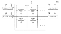
- FIG. 1 is a diagram illustrating a configuration of a semiconductor device of a first embodiment.
- this semiconductor device 1000 includes a memory array 98 , a plurality of word lines WL, a plurality of bit line pairs BT and BB, a plurality of word line drivers 502 , a first power source Vdd, and a plurality of assist drivers 504 .
- the memory array 98 includes a plurality of memory cells 500 arranged in matrix.
- the word lines WL are provided and correspond respectively to the rows of the memory array 98 .
- the word lines WL are coupled to the memory cells 500 of the corresponding rows.
- the bit line pair BT and BB is provided and corresponds respectively to the columns of the memory array 98 .
- the bit line pair BT and BB is coupled to the memory cells 500 of the corresponding columns.
- the word line drivers 502 are coupled to one ends of the word lines WL. When a corresponding row is selected, one end of the word line WL is coupled to the first power source Vdd.
- the assist drivers 504 are coupled to the other ends of the word lines WL.
- the other ends of the word lines WL are coupled to the power sources Vdd in accordance with a voltage of the other ends of the word lines WL.
- a voltage of the other end of the word line WL is caused to rise by the assist driver 504 .
- the assist driver 504 it is possible to prevent that the rising speed of a voltage in a position far from the word line driver 502 is lower than the rising speed of a voltage in a position close to the word line driver 502 .
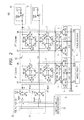
- FIG. 2 is a diagram illustrating a configuration of a semiconductor device of a second embodiment.
- a semiconductor device 100 includes a memory array 62 , a plurality of word lines WL, a plurality of bit line pairs BT and BB, a plurality of word line drivers 22 , a plurality of assist drivers 10 , a plurality of column selectors 4 , a plurality of pre-charge circuits 3 , a control circuit/address decoder 21 , a plurality of write drivers 5 , and a plurality of sense amplifiers 6 .
- the memory array 62 includes a plurality of memory cells 1 arranged in matrix.
- the memory cells 1 are represented in the form of two rows and two columns.
- the memory cells 1 are SRAM (Static Random Access Memory) cells.
- Each of the memory cells 1 includes PMOS (Metal-Oxide-Semiconductor) transistors P 1 and P 2 as load transistors, NMOS transistors N 1 and N 2 as driver transistors, and NMOS transistors N 20 and N 21 as access transistors.
- PMOS Metal-Oxide-Semiconductor
- the sources of the load transistors P 1 and P 2 are both coupled to an internal power source voltage Vdd, the drains thereof are coupled respectively to memory nodes A and B, and the gates thereof are coupled respectively to the memory nodes B and A.
- the sources of the driver transistors N 1 and N 2 are both coupled to a grounded power source (grounded), the drains thereof are coupled respectively to the memory nodes A and B, and the gates thereof are coupled respectively to the memory nodes B and A.
- the sources of the access transistors N 20 and N 21 are coupled respectively to the memory nodes A and B, the drains thereof are coupled to corresponding bit lines BT and BB, and the gates thereof are both coupled to corresponding word lines WL.
- a PMOS transistor P 1 and an NMOS transistor N 1 form an inverter, and output an inverted signal of data written into the memory node B to the memory node A.
- a PMOS transistor P 2 and an NMOS transistor N 2 form an inverter, and output an inverted signal of data written into the memory node A to the memory node B.
- the PMOS transistors P 1 and P 2 and the NMOS transistors N 1 and N 2 form latch circuits which keep data written in the memory nodes A and B.
- the word lines WL are provided and respectively correspond to the rows of the memory array 62 .
- the word lines WL are coupled to the memory cells 500 of the corresponding rows.
- the bit line pairs BT and BB are provided and correspond respectively to the columns of the memory array 62 .
- the bit line pairs BT and BB are coupled to the memory cells 500 of the corresponding columns.
- the control circuit/address decoder 21 includes a row decoder and a column decoder, to drive the address-designated word line WL into a selection state.
- the row decoder generates a row selection signal in accordance with a row address signal, while the column decoder selects a bit line pair corresponding to a selected column in accordance with a column address signal.
- the row decoder decodes a row address signal to generate a row selection signal, at the time of reading operation or writing operation. For example, at the time of selecting the 0 th row illustrated in FIG. 2 , the row decoder activates and makes select signals XU 0 and XL 0 into a high level. At the time of selecting the 1 st row illustrated in FIG. 2 , it activates and makes select signals XU 1 and XL 1 into a high level.
- the column decoder decodes a column address signal to generate a column selection signal. For example, the column decoder activates and makes a select signal Y 0 into a high level, at the time of selecting the 0 th column illustrated in FIG. 2 , and activates and makes a select signal Y 1 into a high level, at the time of selecting the 1 st column illustrated in FIG. 2 .
- a column selector 4 includes an inverter IV 1 , an inverter IV 2 , PMOS transistors P 5 and P 6 , and NMOS transistors N 5 and N 6 .
- the inverter IV 1 in the column selector 4 of the 0 th column receives a select signal Y 0 .
- the inverter IV 1 in the column selector 4 of the 1 st column receives a select signal Y 1 .
- the inverter IV 2 receives the output of the inverter IV 1 .
- the PMOS transistor P 5 and the NMOS transistor N 5 are provided between the bit line BT, an output node O of a write driver 5 , and an input node I of a sense amplifier 6 .
- the gate of the PMOS transistor P 5 receives the output of the inverter IV 1 .
- the gate of the NMOS transistor N 5 receives the output of the inverter IV 2 .
- the PMOS transistor P 6 and the NMOS transistor N 6 are provided between the bit line BB, an inverted output node NO of the write driver 5 , and an inverted input node NI of the sense amplifier 6 .
- the gate of the PMOS transistor P 6 receives the output of the inverter IV 1 .
- the gate of the NMOS transistor N 6 receives the output of the inverter IV 2 .
- a pre-charge circuit 3 includes PMOS transistors P 3 , P 4 , and P 20 .
- the PMOS transistor P 3 is provided between the power source Vdd and the bit line BT.
- the PMOS transistor P 3 receives the output of the inverter IV 2 .
- the PMOS transistor P 4 is provided between the power source Vdd and the bit line BB.
- the PMOS transistor P 4 receives the output of the inverter IV 2 .
- the PMOS transistor P 20 is provided between the bit line BT and the bit line BB.
- the gate of the PMOS transistor P 20 receives the output of the inverter IV 2 .
- the PMOS transistors P 3 , P 4 , P 4 , and P 20 will be ON, and the bit line pair BT and BB of the 0 th column is pre-charged with the voltage Vdd.
- the PMOS transistors P 3 , P 4 , P 4 , and P 20 will be OFF, and precharging of the bit line pair BT and BB of the 0 th column is completed.
- the PMOS transistors P 5 and P 6 and the NMOS transistors N 5 and N 6 are ON.
- the bit line pair BT and BB of the 0 th column is coupled to the write driver 5 and the sense amplifier 6 .
- the PMOS transistors P 3 , P 4 , P 4 , and P 20 are ON.
- the bit line pair BT and BB of the 1 st column is pre-charged with the voltage Vdd.
- the PMOS transistors P 3 , P 4 , P 4 , and P 20 will be OFF, and precharging of the bit line pair BT and BB of the 1 st column is completed.
- the PMOS transistors P 5 and P 6 and the NMOS transistors N 5 and N 6 will be ON.
- the bit line pair BT and BB of the 1 st column is coupled to the write driver 5 and the sense amplifier 6 .
- Each of the write driver 5 and the sense amplifier 6 is provided for each adjacent two columns, and coupled to the bit line pair BT and BB of the adjacent two columns.
- Each of the write driver 5 and the sense amplifier 6 is shared commonly by the two columns.
- the memory array 62 is formed in a horizontally long shape.
- the word lines WL are formed long, exhibiting a large effect of this embodiment.
- the write driver 5 outputs a voltage corresponding to the write data to the bit line pair BT and BB of a selected one of the 0 th and 1 st columns, that is, (high level, low level) or (low level, or high level), at the time of writing data to the memory cell 1 .
- the sense amplifier 6 amplifies a potential difference of the bit line pair BT and BB of the selected column of the 0 th and 1 st columns, at the time of reading data from the memory cell 1 .
- Word line drivers 22 and assist drivers 10 are provided and correspond to the word lines WL of the memory array 62 .
- Each of the word line driver 22 is coupled to the front end X of a corresponding word line WL.
- the assist driver 10 is coupled to the terminal end Y of a corresponding word line WL.
- the word line driver 22 couples an end of the coupled word line WL to the power source Vdd, when a corresponding row is selected.
- the word line driver 22 includes an inverter having a NAND circuit NAN 1 , a PMOS transistor P 7 , and an NMOS transistor N 7 .
- the input of this inverter is coupled to the output of the NAND circuit NAN 1 , while the output of this inverter is coupled to the front end of the word line WL.
- the NAND circuit NAN 1 in the word line driver 22 of the 0 th row receives the select signals XU 0 and XL 0 .
- the select signals XU 0 and XL 0 are at a high level, and the output of the NAND circuit NAN 1 is at a low level.
- the 0 th row is not selected, at least one of the select signals XU 0 and XL 0 is at a low level, and the output of the NAND circuit NAN 1 is at a high level.
- the NAND circuit NAN 1 in the word line driver 22 of the 1 st row receives the select signals XU 1 and XL 1 .
- the select signals XU 1 and XL 1 are at a high level, and the output of the NAND circuit NAN 1 is at a low level.
- the 1 st row is not selected, at least one of the select signals XU 1 and XL 1 is at a low level, and the output of the NAND circuit NAN 1 is at a high level.
- the PMOS transistor P 7 When the output of the NAND circuit NAN 1 is at a low level, the PMOS transistor P 7 is ON, and the NMOS transistor N 7 is OFF. As a result, the front end X of the word line WL is coupled to the power source Vdd, and the voltage of the front end of the word line WL rises. This rise of the voltage is gradually transmitted to the end terminal of the word line WL.
- the PMOS transistor P 7 When the output of the NAND circuit NAN 1 is at a high level, the PMOS transistor P 7 is OFF, and the NMOS transistor N 7 is ON. As a result, the front end X of the word line WL is grounded, and the voltage of the front end of the word line WL rises. This rise of the voltage is gradually transmitted to the terminal end of the word line WL.
- the assist driver 10 couples or disconnects the terminal end Y of a corresponding word line WL to or from the power source Vdd, in accordance with the voltage of the other end of the corresponding word line WL.
- the assist driver 10 includes an inverter IV 3 and a PMOS transistor P 8 .
- the PMOS transistor P 8 is provided between the terminal end Y of the word line WL and the power source Vdd.
- the input of the inverter IV 3 is coupled to the end terminal Y of the word line WL, while the output of the inverter IV 3 is coupled to the gate of the PMOS transistor P 8 .
- FIG. 3 is a diagram illustrating voltage changes of the front end and the terminal end of a word line WL, and an assist driver 10 , in the second embodiment.
- the terminal end Y of the word line WL is coupled to the power source Vdd at the time of activating the word line WL.
- the terminal end Y of the word line WL and the power source Vdd are disconnected at the time of inactivating the word line WL.
- FIG. 4 is a diagram illustrating a configuration of a semiconductor device of a third embodiment.
- the assist control circuit 12 includes two stages of inverters IV 4 and IV 5 .
- the control circuit/address decoder 21 transmits a control signal pulse PL to the assist control circuit 12 and an assist driver 11 , through a signal wiring LA.
- the signal wiring LA is provided outside the memory array 62 , in a direction horizontal to the substrate where the semiconductor device 200 is implemented.
- the inverter IV 4 receives a control signal pulse PL from the control circuit/address decoder 21 .
- the inverter IV 5 receives an output from the inverter IV 4 .
- the assist driver 11 includes a NAND circuit NAN 2 and a PMOST transistor P 8 .
- the PMOS transistor P 8 is provided between the terminal end Y of the word line WL and the power source Vdd.
- the PMOS transistor P 8 is ON, when the voltage of the terminal end Y of the word line WL increases up to a predetermined value, at the rising time of the word line WL. It is OFF in response to a control signal from the control circuit/address decoder 21 , at the falling time of the word line WL.
- the input of the NAND circuit NAN 2 is coupled to the terminal end Y of the word line WL, while the other input thereof is coupled to the inverter IV 5 .
- the output of the NAND circuit NAN 2 is coupled to the gate of the PMOS transistor P 8 .
- the control signal pulse PL is output from the control circuit/address decoder 21 , and input to the NAND circuit NAN 2 through the inverters IV 4 and IV 5 .
- This control signal pulse PL is at a high level in a period since the rising start time of the word line WL until the voltage of the terminal end Y of the word line WL reaches Vdd, and the pulse is at a low level in a period since the falling start time of the word line WL until the voltage of the terminal end Y of the word line WL reaches a ground voltage (0V).
- FIG. 5 is a diagram illustrating voltages changes in the front end and terminal end of a word line WL, and an assist driver, in the third embodiment.
- the voltage of the terminal end Y of the word line WL is sufficiently high and exceeds a threshold value of the inverter included in the NAND circuit NAN 2 , the voltage of the output terminal Z of the NAND circuit NAN 2 in the assist driver 10 is at a low level. Then, the PMOS transistor P 8 in the assist driver 10 will be ON. As a result, the power source Vdd is coupled to the terminal end Y of the word line WL, thus accelerating the rise of the voltage at the terminal end Y, as illustrated by ( 3 ).
- the word line WL is arranged in the semiconductor layer right above an area in which the memory cells 1 are arranged, it is hardly designed that thick word lines WL are formed.
- the control signal pulse PL output from the control circuit/address decoder 21 is transmitted to the assist control circuit 12 and the assist driver 11 through the signal wiring LA arranged outside the memory array 62 .
- FIG. 6 is a diagram illustrating a semiconductor device of the fourth embodiment.
- An assist driver 13 includes a NAND circuit NAN 3 , a PMOS transistor P 8 , and a delay circuit DL.
- the delay circuit DL includes three stages of inverters IV 6 , IV 7 , and IV 8 .
- the input of the inverter IV 6 is coupled to the terminal end Y of the word line WL, the input of the inverter IV 7 is coupled to the output of the inverter IV 6 , and the input of the inverter IV 8 is coupled to the input of the inverter IV 7 .
- the PMOS transistor P 8 is provided between the terminal end Y of the word line WL and the power source Vdd.
- the PMOS transistor P 8 will be ON by a one-shot pulse which will be at a low level for a predetermined period of time since the voltage of the terminal end of the word line WL has risen up to a predetermined value, at the rising time of the word line WL.
- One input of the NAND circuit NAN 3 is coupled to the terminal end Y of the word line WL, while the other input thereof is coupled to the output of the inverter IN 8 .
- the output of the NAND circuit NAN 3 is coupled to the gate of the PMOS transistor P 8 .
- FIG. 7 is a diagram illustrating voltage changes of the front end and terminal end of a word line WL, and an assistant driver 13 , in the fourth embodiment.
- a one-shot pulse is generated by the delay circuit DL and the NAND circuit NAN 3 .
- This one-shot pulse is for causing the voltage of the output terminal Y of the NAND circuit NAN 3 to be at a low level in a period since the time t 2 until a delay time dt by the delay circuit DL, as illustrated by ( 3 ).
- the PMOS transistor P 8 in the assist driver 10 will be ON.
- the power source Vdd is coupled to the terminal end Y of the word line WL, thus accelerating the rise of the voltage at the terminal end Y, as illustrated by ( 3 ).
- the memory cells 1 of the above embodiment are vertically long memory cells.
- the semiconductor device of this embodiment includes laterally long memory cells as memory cells.
- a memory cell MC of this embodiment includes load transistors (P-channel MOS transistors) 41 and 42 , driver transistors (N-channel MOS transistors) 43 and 44 , and access transistors (N-channel MOS transistors) 45 and 46 . See FIG. 8A .
- This memory cell 500 differs from the memory cell 1 , in the layout of the transistors 41 to 46 .
- the laterally long memory cell MC is formed over the surfaces of one N-type well NW and P-type wells PW and PW arranged on both sides thereof.
- Those electrodes formed of a polysilicon layer include a gate electrode GE 1 extending in an X direction of the illustration from the N-type well NW to one P-type well PW, a gate electrode GE 2 extending in the X direction of the illustration from the N-type well NW to the other P-type well PW, a gate electrode GE 3 extending in the X direction of the illustration over the one P-type well PW, and a gate electrode GE 4 extending in the X direction over the other P-type well PW.
- active layers including an N-type active layer NA 1 crossing the gate electrodes GE 1 and GE 3 in the one P-type well PW, an N-type active layer NA 2 crossing the gate electrodes GE 2 and GE 4 in the other P-type well PW, and P-type active layers PA 1 and PA 2 crossing the gate electrodes GE 1 and GE 2 in the N-type well NW.
- the gate electrode GE 1 and the P-type active layer PA 1 form the P-channel MOS transistor 41 .
- the gate electrode GE 2 and the P-type active layer PA 2 form the P-channel MOS transistor 42 .
- the gate electrode GE 1 and the N-type active layer NA 1 form the N-channel MOS transistor 43 .
- the gate electrode GE 3 and the N-type active layer NA 1 form the N-channel MOS transistor 45 .
- the gate electrode GE 2 and the N-type active layer NA 2 form the N-channel MOS transistor 44 .
- the gate electrode GE 4 and the N-type active layer NA 2 form the N-channel MOS transistor 46 .
- a local wiring LL 1 is formed across the center section of the N-type active layer NA 1 , one end section of the P-type active layer PA 1 , and one end section of the gate electrode GE 2 .
- a local wiring LL 2 is formed across the center section of the N-type active layer NA 2 , one end section of the P-type active layer PA 1 , and one end section of the gate electrode GE 1 .
- those parts in which the active layers NA 1 and PA 1 overlap the local wiring LL 1 are conductive.
- Those parts in which the active layers NA 2 and PA 2 overlap the local wiring LL 2 are conductive.
- the gate electrode GE 2 and the local wiring LL 1 are coupled to each other through a contact hole CH, and the gate electrode GE 1 and the local wiring LL 2 are coupled to each other through a contact hole CH.
- a plurality of metal wirings ML extending in the X direction of the illustration are formed of a first aluminum wiring layer. Further, above this, a memory cell grounding wiring MGL, the bit line BL, a memory cell power source wiring MVL, the bit line/BL, and a memory cell grounding wiring MGL, extending in a Y direction of the illustration, are formed of a second aluminum wiring layer. Of the metal wirings ML, a metal wiring crossing the center section of the memory cell MC is the word line WL.
- One end (the source of the P-channel MOS transistor 41 ) of the P-type active layer PA 1 is coupled to the memory cell power source wiring MVL through the contact hole CH, the metal wiring ML, and a via hole VH.
- One end (the source of the P-channel MOS transistor 42 ) of the P-type active layer PA 2 is coupled to the memory cell power source wiring MVL through the contact hole CH, the metal wiring ML, and the via hole VH.
- One end (the source of the N-channel MOS transistor 43 ) of the N-type active layer NA 1 is coupled to the memory cell grounding wiring MGL through the contact hole CH, the metal wiring ML, and the via hole VH.
- One end (the source of the N-channel MOS transistor 44 ) of the N-type active layer NA 2 is coupled to the memory cell grounding wiring MGL through the contact hole CH, the memory wiring ML, and the via hole VH.
- the other end (the drain of the N-channel MOS transistor 45 ) of the N-type active layer NA 1 is coupled to the bit line BL through the contact hole CH, the metal wiring ML, and the via hole VH.
- the other end (the drain of the N-channel MOS transistor 46 ) of the N-type active layer NA 2 is coupled to the bit line/BL through the contact hole CH, the metal wiring ML, and the via hole VH.
- the gate electrodes GE 3 and GE 4 are coupled to the word line WL respectively through the contact holes CH.
- the word lines WL of this embodiment are formed long.
- the long word lines WL cause an apparent problem, at the time of activating the word line WL, that the rising speed of a voltage in a position far from the word line driver 22 is lower than the rising speed of a voltage in a position close to the word line driver 22 .
- the semiconductor device of this embodiment includes the assist drivers 10 , 11 , and 13 described in the first to fourth embodiments, thereby preventing this problem.
- the write driver 5 and the sense amplifier 6 are provided for each adjacent two columns, and coupled to the bit line pair BT and BB of the adjacent two columns.
- the present invention is not limited to this.
- the write driver 5 and the sense amplifier 6 may be provided for each adjacent three or more columns, and may be coupled to the bit line pair BT and BB of the adjacent three or more columns.
Landscapes
- Engineering & Computer Science (AREA)
- Microelectronics & Electronic Packaging (AREA)
- Computer Hardware Design (AREA)
- Multimedia (AREA)
- Static Random-Access Memory (AREA)
- Dram (AREA)
Priority Applications (2)
| Application Number | Priority Date | Filing Date | Title |
|---|---|---|---|
| US15/627,535 US10255970B2 (en) | 2015-09-11 | 2017-06-20 | Semiconductor device |
| US16/145,342 US10354722B2 (en) | 2015-09-11 | 2018-09-28 | Semiconductor device |
Applications Claiming Priority (2)
| Application Number | Priority Date | Filing Date | Title |
|---|---|---|---|
| JP2015179683A JP6469554B2 (ja) | 2015-09-11 | 2015-09-11 | 半導体装置 |
| JP2015-179683 | 2015-09-11 |
Related Child Applications (1)
| Application Number | Title | Priority Date | Filing Date |
|---|---|---|---|
| US15/627,535 Continuation US10255970B2 (en) | 2015-09-11 | 2017-06-20 | Semiconductor device |
Publications (2)
| Publication Number | Publication Date |
|---|---|
| US20170076785A1 US20170076785A1 (en) | 2017-03-16 |
| US9721647B2 true US9721647B2 (en) | 2017-08-01 |
Family
ID=58238935
Family Applications (3)
| Application Number | Title | Priority Date | Filing Date |
|---|---|---|---|
| US15/212,162 Active US9721647B2 (en) | 2015-09-11 | 2016-07-15 | Semiconductor device |
| US15/627,535 Active US10255970B2 (en) | 2015-09-11 | 2017-06-20 | Semiconductor device |
| US16/145,342 Active US10354722B2 (en) | 2015-09-11 | 2018-09-28 | Semiconductor device |
Family Applications After (2)
| Application Number | Title | Priority Date | Filing Date |
|---|---|---|---|
| US15/627,535 Active US10255970B2 (en) | 2015-09-11 | 2017-06-20 | Semiconductor device |
| US16/145,342 Active US10354722B2 (en) | 2015-09-11 | 2018-09-28 | Semiconductor device |
Country Status (3)
| Country | Link |
|---|---|
| US (3) | US9721647B2 (enExample) |
| JP (1) | JP6469554B2 (enExample) |
| CN (1) | CN106531206B (enExample) |
Cited By (4)
| Publication number | Priority date | Publication date | Assignee | Title |
|---|---|---|---|---|
| US20170287553A1 (en) * | 2015-09-11 | 2017-10-05 | Renesas Electronics Corporation | Semiconductor device |
| US10157665B2 (en) * | 2016-11-01 | 2018-12-18 | Taiwan Semiconductor Manufacturing Co., Ltd. | Word-line enable pulse generator, SRAM and method for adjusting word-line enable time of SRAM |
| US20210249059A1 (en) * | 2020-02-11 | 2021-08-12 | Taiwan Semiconductor Manufacturing Company Limited | Word Line Driver for Low Voltage Operation |
| US11670360B2 (en) | 2020-10-30 | 2023-06-06 | Samsung Electronics Co., Ltd. | Integrated circuit including cell array with word line assist cells |
Families Citing this family (8)
| Publication number | Priority date | Publication date | Assignee | Title |
|---|---|---|---|---|
| US10943645B2 (en) * | 2018-07-31 | 2021-03-09 | Taiwan Semiconductor Manufacturing Company, Ltd | Memory device with a booster word line |
| JP7270451B2 (ja) | 2019-04-26 | 2023-05-10 | ルネサスエレクトロニクス株式会社 | 半導体装置および半導体装置の駆動方法 |
| US11189336B2 (en) * | 2019-10-30 | 2021-11-30 | Taiwan Semiconductor Manufacturing Company, Ltd. | Word line driving device for minimizing RC delay |
| CN112750479A (zh) * | 2019-10-30 | 2021-05-04 | 台湾积体电路制造股份有限公司 | 字线驱动装置 |
| JP2021108307A (ja) | 2019-12-27 | 2021-07-29 | キオクシア株式会社 | 半導体記憶装置 |
| US11211113B1 (en) * | 2020-08-18 | 2021-12-28 | Micron Technology, Inc. | Integrated assemblies comprising wordlines having ends selectively shunted to low voltage for speed transitioning |
| US11521670B2 (en) * | 2020-11-12 | 2022-12-06 | Micron Technology, Inc. | Word lines coupled to pull-down transistors, and related devices, systems, and methods |
| US12525261B2 (en) | 2023-05-01 | 2026-01-13 | Taiwan Semiconductor Manufacturing Company, Ltd. | Memory devices with reduced bit line capacitance and methods of manufacturing thereof |
Citations (2)
| Publication number | Priority date | Publication date | Assignee | Title |
|---|---|---|---|---|
| US20110149674A1 (en) * | 2009-12-22 | 2011-06-23 | Gus Yeung | Integrated circuit memory with word line driving helper circuits |
| JP2014099225A (ja) | 2012-11-14 | 2014-05-29 | Renesas Electronics Corp | 半導体装置 |
Family Cites Families (13)
| Publication number | Priority date | Publication date | Assignee | Title |
|---|---|---|---|---|
| JPS55150189A (en) | 1979-05-10 | 1980-11-21 | Nec Corp | Memory circuit |
| JPS60226095A (ja) * | 1984-04-25 | 1985-11-11 | Hitachi Micro Comput Eng Ltd | 半導体記憶装置 |
| JPS63276793A (ja) * | 1987-05-07 | 1988-11-15 | Nec Ic Microcomput Syst Ltd | ワ−ド線駆動回路 |
| JPH06203579A (ja) * | 1993-01-08 | 1994-07-22 | Fujitsu Ltd | 出力回路及び記憶装置 |
| JP3908493B2 (ja) * | 2001-08-30 | 2007-04-25 | 株式会社東芝 | 電子回路及び半導体記憶装置 |
| JP4439167B2 (ja) * | 2002-08-30 | 2010-03-24 | 株式会社ルネサステクノロジ | 半導体記憶装置 |
| US7064981B2 (en) * | 2004-08-04 | 2006-06-20 | Micron Technology, Inc. | NAND string wordline delay reduction |
| JP4912016B2 (ja) * | 2005-05-23 | 2012-04-04 | ルネサスエレクトロニクス株式会社 | 半導体記憶装置 |
| JP4631743B2 (ja) | 2006-02-27 | 2011-02-16 | ソニー株式会社 | 半導体装置 |
| US7379354B2 (en) * | 2006-05-16 | 2008-05-27 | Texas Instruments Incorporated | Methods and apparatus to provide voltage control for SRAM write assist circuits |
| US7733686B2 (en) * | 2006-12-30 | 2010-06-08 | Texas Instruments Incorporated | Pulse width control for read and write assist for SRAM circuits |
| JP2014067942A (ja) * | 2012-09-27 | 2014-04-17 | Toshiba Corp | 不揮発性半導体記憶装置 |
| JP6469554B2 (ja) * | 2015-09-11 | 2019-02-13 | ルネサスエレクトロニクス株式会社 | 半導体装置 |
-
2015
- 2015-09-11 JP JP2015179683A patent/JP6469554B2/ja active Active
-
2016
- 2016-07-15 US US15/212,162 patent/US9721647B2/en active Active
- 2016-08-22 CN CN201610704791.5A patent/CN106531206B/zh active Active
-
2017
- 2017-06-20 US US15/627,535 patent/US10255970B2/en active Active
-
2018
- 2018-09-28 US US16/145,342 patent/US10354722B2/en active Active
Patent Citations (2)
| Publication number | Priority date | Publication date | Assignee | Title |
|---|---|---|---|---|
| US20110149674A1 (en) * | 2009-12-22 | 2011-06-23 | Gus Yeung | Integrated circuit memory with word line driving helper circuits |
| JP2014099225A (ja) | 2012-11-14 | 2014-05-29 | Renesas Electronics Corp | 半導体装置 |
Cited By (7)
| Publication number | Priority date | Publication date | Assignee | Title |
|---|---|---|---|---|
| US20170287553A1 (en) * | 2015-09-11 | 2017-10-05 | Renesas Electronics Corporation | Semiconductor device |
| US10255970B2 (en) * | 2015-09-11 | 2019-04-09 | Renesas Electronics Corporation | Semiconductor device |
| US10354722B2 (en) * | 2015-09-11 | 2019-07-16 | Renesas Electronics Corporation | Semiconductor device |
| US10157665B2 (en) * | 2016-11-01 | 2018-12-18 | Taiwan Semiconductor Manufacturing Co., Ltd. | Word-line enable pulse generator, SRAM and method for adjusting word-line enable time of SRAM |
| US20210249059A1 (en) * | 2020-02-11 | 2021-08-12 | Taiwan Semiconductor Manufacturing Company Limited | Word Line Driver for Low Voltage Operation |
| US11170830B2 (en) * | 2020-02-11 | 2021-11-09 | Taiwan Semiconductor Manufacturing Company Limited | Word line driver for low voltage operation |
| US11670360B2 (en) | 2020-10-30 | 2023-06-06 | Samsung Electronics Co., Ltd. | Integrated circuit including cell array with word line assist cells |
Also Published As
| Publication number | Publication date |
|---|---|
| CN106531206B (zh) | 2022-05-27 |
| US10255970B2 (en) | 2019-04-09 |
| US20170076785A1 (en) | 2017-03-16 |
| JP2017054570A (ja) | 2017-03-16 |
| JP6469554B2 (ja) | 2019-02-13 |
| US20190035456A1 (en) | 2019-01-31 |
| US20170287553A1 (en) | 2017-10-05 |
| CN106531206A (zh) | 2017-03-22 |
| US10354722B2 (en) | 2019-07-16 |
Similar Documents
| Publication | Publication Date | Title |
|---|---|---|
| US10354722B2 (en) | Semiconductor device | |
| US10510400B2 (en) | Semiconductor storage device | |
| US7693004B2 (en) | Semiconductor memory device | |
| US7697320B2 (en) | Semiconductor memory device | |
| US9865336B2 (en) | Semiconductor memory with data line capacitive coupling | |
| CN103310831B (zh) | 存储单元的写入操作中的信号跟踪 | |
| US8830784B2 (en) | Negative word line driver for semiconductor memories | |
| US8144523B2 (en) | Semiconductor storage device | |
| US8045389B2 (en) | Semiconductor memory device | |
| US7489581B2 (en) | Semiconductor memory | |
| US8598931B2 (en) | Delay circuit | |
| JP6802313B2 (ja) | デュアルポートsram | |
| JP2010187020A (ja) | 半導体集積回路装置 | |
| JP2018092698A (ja) | 半導体記憶装置 | |
| US9183905B2 (en) | Delay circuit and semiconductor memory device | |
| JP2014139860A (ja) | 半導体集積回路装置 | |
| JP2015111489A (ja) | 半導体集積回路装置 |
Legal Events
| Date | Code | Title | Description |
|---|---|---|---|
| AS | Assignment |
Owner name: RENESAS ELECTRONICS CORPORATION, JAPAN Free format text: ASSIGNMENT OF ASSIGNORS INTEREST;ASSIGNOR:ISHII, YUICHIRO;REEL/FRAME:039173/0873 Effective date: 20160419 |
|
| STCF | Information on status: patent grant |
Free format text: PATENTED CASE |
|
| MAFP | Maintenance fee payment |
Free format text: PAYMENT OF MAINTENANCE FEE, 4TH YEAR, LARGE ENTITY (ORIGINAL EVENT CODE: M1551); ENTITY STATUS OF PATENT OWNER: LARGE ENTITY Year of fee payment: 4 |
|
| MAFP | Maintenance fee payment |
Free format text: PAYMENT OF MAINTENANCE FEE, 8TH YEAR, LARGE ENTITY (ORIGINAL EVENT CODE: M1552); ENTITY STATUS OF PATENT OWNER: LARGE ENTITY Year of fee payment: 8 |