US9654745B2 - Rapid multi-spectral imaging methods and apparatus and applications for cancer detection and localization - Google Patents
Rapid multi-spectral imaging methods and apparatus and applications for cancer detection and localization Download PDFInfo
- Publication number
- US9654745B2 US9654745B2 US13/635,682 US201113635682A US9654745B2 US 9654745 B2 US9654745 B2 US 9654745B2 US 201113635682 A US201113635682 A US 201113635682A US 9654745 B2 US9654745 B2 US 9654745B2
- Authority
- US
- United States
- Prior art keywords
- light
- image
- narrow
- spectral
- bands
- Prior art date
- Legal status (The legal status is an assumption and is not a legal conclusion. Google has not performed a legal analysis and makes no representation as to the accuracy of the status listed.)
- Active, expires
Links
- 238000000034 method Methods 0.000 title claims abstract description 70
- 238000000701 chemical imaging Methods 0.000 title claims description 50
- 238000001514 detection method Methods 0.000 title description 20
- 206010028980 Neoplasm Diseases 0.000 title description 14
- 201000011510 cancer Diseases 0.000 title description 13
- 230000004807 localization Effects 0.000 title description 4
- 230000003595 spectral effect Effects 0.000 claims abstract description 135
- 238000003384 imaging method Methods 0.000 claims abstract description 71
- 238000004422 calculation algorithm Methods 0.000 claims abstract description 52
- 238000001228 spectrum Methods 0.000 claims abstract description 51
- 238000010521 absorption reaction Methods 0.000 claims abstract description 38
- 230000000877 morphologic effect Effects 0.000 claims abstract description 32
- 239000011159 matrix material Substances 0.000 claims abstract description 16
- 210000001519 tissue Anatomy 0.000 claims description 75
- 238000005286 illumination Methods 0.000 claims description 73
- 238000005259 measurement Methods 0.000 claims description 33
- 238000012545 processing Methods 0.000 claims description 30
- 238000012937 correction Methods 0.000 claims description 15
- 239000002245 particle Substances 0.000 claims description 10
- 238000000985 reflectance spectrum Methods 0.000 claims description 9
- 230000008569 process Effects 0.000 claims description 8
- 238000009826 distribution Methods 0.000 claims description 7
- 108010054147 Hemoglobins Proteins 0.000 claims description 6
- 102000001554 Hemoglobins Human genes 0.000 claims description 6
- XLYOFNOQVPJJNP-UHFFFAOYSA-N water Substances O XLYOFNOQVPJJNP-UHFFFAOYSA-N 0.000 claims description 4
- 239000004065 semiconductor Substances 0.000 claims description 3
- INGWEZCOABYORO-UHFFFAOYSA-N 2-(furan-2-yl)-7-methyl-1h-1,8-naphthyridin-4-one Chemical compound N=1C2=NC(C)=CC=C2C(O)=CC=1C1=CC=CO1 INGWEZCOABYORO-UHFFFAOYSA-N 0.000 claims description 2
- 108010064719 Oxyhemoglobins Proteins 0.000 claims description 2
- 108010002255 deoxyhemoglobin Proteins 0.000 claims description 2
- 239000004973 liquid crystal related substance Substances 0.000 claims description 2
- 210000004877 mucosa Anatomy 0.000 claims description 2
- 229910052724 xenon Inorganic materials 0.000 claims description 2
- FHNFHKCVQCLJFQ-UHFFFAOYSA-N xenon atom Chemical compound [Xe] FHNFHKCVQCLJFQ-UHFFFAOYSA-N 0.000 claims description 2
- 238000003491 array Methods 0.000 claims 1
- 230000002194 synthesizing effect Effects 0.000 claims 1
- 230000001766 physiological effect Effects 0.000 abstract description 13
- 230000035479 physiological effects, processes and functions Effects 0.000 abstract description 2
- 230000001808 coupling effect Effects 0.000 abstract 1
- 238000000799 fluorescence microscopy Methods 0.000 description 14
- 230000003287 optical effect Effects 0.000 description 12
- 238000004458 analytical method Methods 0.000 description 10
- 230000006870 function Effects 0.000 description 10
- 238000005457 optimization Methods 0.000 description 10
- 239000008280 blood Substances 0.000 description 9
- 210000004369 blood Anatomy 0.000 description 9
- 238000001839 endoscopy Methods 0.000 description 9
- 230000008901 benefit Effects 0.000 description 8
- 238000001727 in vivo Methods 0.000 description 8
- 230000035945 sensitivity Effects 0.000 description 8
- 239000000872 buffer Substances 0.000 description 7
- 239000000835 fiber Substances 0.000 description 7
- 238000000338 in vitro Methods 0.000 description 7
- 238000004611 spectroscopical analysis Methods 0.000 description 7
- 238000013459 approach Methods 0.000 description 6
- 230000008878 coupling Effects 0.000 description 6
- 238000010168 coupling process Methods 0.000 description 6
- 238000005859 coupling reaction Methods 0.000 description 6
- 230000033001 locomotion Effects 0.000 description 6
- 238000013507 mapping Methods 0.000 description 6
- 239000000523 sample Substances 0.000 description 6
- 230000004044 response Effects 0.000 description 5
- 230000000287 tissue oxygenation Effects 0.000 description 5
- 210000004027 cell Anatomy 0.000 description 4
- 230000000694 effects Effects 0.000 description 4
- 238000000862 absorption spectrum Methods 0.000 description 3
- 238000007405 data analysis Methods 0.000 description 3
- 238000010586 diagram Methods 0.000 description 3
- 238000009792 diffusion process Methods 0.000 description 3
- 238000009472 formulation Methods 0.000 description 3
- 230000003902 lesion Effects 0.000 description 3
- 230000003211 malignant effect Effects 0.000 description 3
- 239000000203 mixture Substances 0.000 description 3
- 238000012544 monitoring process Methods 0.000 description 3
- 238000011002 quantification Methods 0.000 description 3
- 206010008263 Cervical dysplasia Diseases 0.000 description 2
- QVGXLLKOCUKJST-UHFFFAOYSA-N atomic oxygen Chemical compound [O] QVGXLLKOCUKJST-UHFFFAOYSA-N 0.000 description 2
- 238000001574 biopsy Methods 0.000 description 2
- 208000007951 cervical intraepithelial neoplasia Diseases 0.000 description 2
- 238000004163 cytometry Methods 0.000 description 2
- 238000003745 diagnosis Methods 0.000 description 2
- 201000010099 disease Diseases 0.000 description 2
- 208000037265 diseases, disorders, signs and symptoms Diseases 0.000 description 2
- 238000002073 fluorescence micrograph Methods 0.000 description 2
- 230000004660 morphological change Effects 0.000 description 2
- 229910052760 oxygen Inorganic materials 0.000 description 2
- 239000001301 oxygen Substances 0.000 description 2
- 238000006213 oxygenation reaction Methods 0.000 description 2
- 230000007170 pathology Effects 0.000 description 2
- 230000005855 radiation Effects 0.000 description 2
- 238000001055 reflectance spectroscopy Methods 0.000 description 2
- 238000011160 research Methods 0.000 description 2
- 238000010183 spectrum analysis Methods 0.000 description 2
- 238000002560 therapeutic procedure Methods 0.000 description 2
- 206010061218 Inflammation Diseases 0.000 description 1
- 206010061523 Lip and/or oral cavity cancer Diseases 0.000 description 1
- 206010058467 Lung neoplasm malignant Diseases 0.000 description 1
- 206010030113 Oedema Diseases 0.000 description 1
- 238000001069 Raman spectroscopy Methods 0.000 description 1
- 239000002250 absorbent Substances 0.000 description 1
- 230000002745 absorbent Effects 0.000 description 1
- 238000007792 addition Methods 0.000 description 1
- 208000021096 adenomatous colon polyp Diseases 0.000 description 1
- 238000000149 argon plasma sintering Methods 0.000 description 1
- 230000005540 biological transmission Effects 0.000 description 1
- 210000004204 blood vessel Anatomy 0.000 description 1
- 238000013276 bronchoscopy Methods 0.000 description 1
- 238000004364 calculation method Methods 0.000 description 1
- 230000008859 change Effects 0.000 description 1
- 238000012512 characterization method Methods 0.000 description 1
- 238000004891 communication Methods 0.000 description 1
- 238000004624 confocal microscopy Methods 0.000 description 1
- 238000013461 design Methods 0.000 description 1
- 238000011161 development Methods 0.000 description 1
- 229920005994 diacetyl cellulose Polymers 0.000 description 1
- 238000011156 evaluation Methods 0.000 description 1
- 230000005284 excitation Effects 0.000 description 1
- 238000000605 extraction Methods 0.000 description 1
- 238000001914 filtration Methods 0.000 description 1
- 238000001506 fluorescence spectroscopy Methods 0.000 description 1
- 238000010191 image analysis Methods 0.000 description 1
- 230000004054 inflammatory process Effects 0.000 description 1
- 230000003993 interaction Effects 0.000 description 1
- 208000028867 ischemia Diseases 0.000 description 1
- 208000012987 lip and oral cavity carcinoma Diseases 0.000 description 1
- 201000005202 lung cancer Diseases 0.000 description 1
- 208000020816 lung neoplasm Diseases 0.000 description 1
- 210000004962 mammalian cell Anatomy 0.000 description 1
- 239000000463 material Substances 0.000 description 1
- 201000001441 melanoma Diseases 0.000 description 1
- 239000011859 microparticle Substances 0.000 description 1
- 210000003470 mitochondria Anatomy 0.000 description 1
- 238000012986 modification Methods 0.000 description 1
- 230000004048 modification Effects 0.000 description 1
- 230000001613 neoplastic effect Effects 0.000 description 1
- 231100001221 nontumorigenic Toxicity 0.000 description 1
- 238000012014 optical coherence tomography Methods 0.000 description 1
- 230000008520 organization Effects 0.000 description 1
- 230000001575 pathological effect Effects 0.000 description 1
- 230000000704 physical effect Effects 0.000 description 1
- 210000004694 pigment cell Anatomy 0.000 description 1
- 239000002243 precursor Substances 0.000 description 1
- 230000008707 rearrangement Effects 0.000 description 1
- 238000001454 recorded image Methods 0.000 description 1
- 230000035939 shock Effects 0.000 description 1
- 238000004088 simulation Methods 0.000 description 1
- 238000006467 substitution reaction Methods 0.000 description 1
- 230000001360 synchronised effect Effects 0.000 description 1
- 238000012360 testing method Methods 0.000 description 1
- 230000009466 transformation Effects 0.000 description 1
- 238000000844 transformation Methods 0.000 description 1
- 231100000588 tumorigenic Toxicity 0.000 description 1
- 230000000381 tumorigenic effect Effects 0.000 description 1
- 238000011144 upstream manufacturing Methods 0.000 description 1
- 239000013598 vector Substances 0.000 description 1
- 210000001835 viscera Anatomy 0.000 description 1
- 238000012800 visualization Methods 0.000 description 1
Images


Classifications
-
- A—HUMAN NECESSITIES
- A61—MEDICAL OR VETERINARY SCIENCE; HYGIENE
- A61B—DIAGNOSIS; SURGERY; IDENTIFICATION
- A61B1/00—Instruments for performing medical examinations of the interior of cavities or tubes of the body by visual or photographical inspection, e.g. endoscopes; Illuminating arrangements therefor
- A61B1/00163—Optical arrangements
- A61B1/00186—Optical arrangements with imaging filters
-
- H04N9/045—
-
- A—HUMAN NECESSITIES
- A61—MEDICAL OR VETERINARY SCIENCE; HYGIENE
- A61B—DIAGNOSIS; SURGERY; IDENTIFICATION
- A61B1/00—Instruments for performing medical examinations of the interior of cavities or tubes of the body by visual or photographical inspection, e.g. endoscopes; Illuminating arrangements therefor
- A61B1/00002—Operational features of endoscopes
- A61B1/00004—Operational features of endoscopes characterised by electronic signal processing
- A61B1/00009—Operational features of endoscopes characterised by electronic signal processing of image signals during a use of endoscope
- A61B1/000096—Operational features of endoscopes characterised by electronic signal processing of image signals during a use of endoscope using artificial intelligence
-
- A—HUMAN NECESSITIES
- A61—MEDICAL OR VETERINARY SCIENCE; HYGIENE
- A61B—DIAGNOSIS; SURGERY; IDENTIFICATION
- A61B1/00—Instruments for performing medical examinations of the interior of cavities or tubes of the body by visual or photographical inspection, e.g. endoscopes; Illuminating arrangements therefor
- A61B1/00002—Operational features of endoscopes
- A61B1/00057—Operational features of endoscopes provided with means for testing or calibration
-
- A—HUMAN NECESSITIES
- A61—MEDICAL OR VETERINARY SCIENCE; HYGIENE
- A61B—DIAGNOSIS; SURGERY; IDENTIFICATION
- A61B1/00—Instruments for performing medical examinations of the interior of cavities or tubes of the body by visual or photographical inspection, e.g. endoscopes; Illuminating arrangements therefor
- A61B1/04—Instruments for performing medical examinations of the interior of cavities or tubes of the body by visual or photographical inspection, e.g. endoscopes; Illuminating arrangements therefor combined with photographic or television appliances
- A61B1/043—Instruments for performing medical examinations of the interior of cavities or tubes of the body by visual or photographical inspection, e.g. endoscopes; Illuminating arrangements therefor combined with photographic or television appliances for fluorescence imaging
-
- A—HUMAN NECESSITIES
- A61—MEDICAL OR VETERINARY SCIENCE; HYGIENE
- A61B—DIAGNOSIS; SURGERY; IDENTIFICATION
- A61B1/00—Instruments for performing medical examinations of the interior of cavities or tubes of the body by visual or photographical inspection, e.g. endoscopes; Illuminating arrangements therefor
- A61B1/04—Instruments for performing medical examinations of the interior of cavities or tubes of the body by visual or photographical inspection, e.g. endoscopes; Illuminating arrangements therefor combined with photographic or television appliances
- A61B1/05—Instruments for performing medical examinations of the interior of cavities or tubes of the body by visual or photographical inspection, e.g. endoscopes; Illuminating arrangements therefor combined with photographic or television appliances characterised by the image sensor, e.g. camera, being in the distal end portion
-
- A—HUMAN NECESSITIES
- A61—MEDICAL OR VETERINARY SCIENCE; HYGIENE
- A61B—DIAGNOSIS; SURGERY; IDENTIFICATION
- A61B1/00—Instruments for performing medical examinations of the interior of cavities or tubes of the body by visual or photographical inspection, e.g. endoscopes; Illuminating arrangements therefor
- A61B1/06—Instruments for performing medical examinations of the interior of cavities or tubes of the body by visual or photographical inspection, e.g. endoscopes; Illuminating arrangements therefor with illuminating arrangements
- A61B1/063—Instruments for performing medical examinations of the interior of cavities or tubes of the body by visual or photographical inspection, e.g. endoscopes; Illuminating arrangements therefor with illuminating arrangements for monochromatic or narrow-band illumination
-
- A—HUMAN NECESSITIES
- A61—MEDICAL OR VETERINARY SCIENCE; HYGIENE
- A61B—DIAGNOSIS; SURGERY; IDENTIFICATION
- A61B1/00—Instruments for performing medical examinations of the interior of cavities or tubes of the body by visual or photographical inspection, e.g. endoscopes; Illuminating arrangements therefor
- A61B1/06—Instruments for performing medical examinations of the interior of cavities or tubes of the body by visual or photographical inspection, e.g. endoscopes; Illuminating arrangements therefor with illuminating arrangements
- A61B1/0638—Instruments for performing medical examinations of the interior of cavities or tubes of the body by visual or photographical inspection, e.g. endoscopes; Illuminating arrangements therefor with illuminating arrangements providing two or more wavelengths
-
- A—HUMAN NECESSITIES
- A61—MEDICAL OR VETERINARY SCIENCE; HYGIENE
- A61B—DIAGNOSIS; SURGERY; IDENTIFICATION
- A61B1/00—Instruments for performing medical examinations of the interior of cavities or tubes of the body by visual or photographical inspection, e.g. endoscopes; Illuminating arrangements therefor
- A61B1/06—Instruments for performing medical examinations of the interior of cavities or tubes of the body by visual or photographical inspection, e.g. endoscopes; Illuminating arrangements therefor with illuminating arrangements
- A61B1/0646—Instruments for performing medical examinations of the interior of cavities or tubes of the body by visual or photographical inspection, e.g. endoscopes; Illuminating arrangements therefor with illuminating arrangements with illumination filters
-
- A—HUMAN NECESSITIES
- A61—MEDICAL OR VETERINARY SCIENCE; HYGIENE
- A61B—DIAGNOSIS; SURGERY; IDENTIFICATION
- A61B1/00—Instruments for performing medical examinations of the interior of cavities or tubes of the body by visual or photographical inspection, e.g. endoscopes; Illuminating arrangements therefor
- A61B1/06—Instruments for performing medical examinations of the interior of cavities or tubes of the body by visual or photographical inspection, e.g. endoscopes; Illuminating arrangements therefor with illuminating arrangements
- A61B1/0655—Control therefor
-
- A—HUMAN NECESSITIES
- A61—MEDICAL OR VETERINARY SCIENCE; HYGIENE
- A61B—DIAGNOSIS; SURGERY; IDENTIFICATION
- A61B1/00—Instruments for performing medical examinations of the interior of cavities or tubes of the body by visual or photographical inspection, e.g. endoscopes; Illuminating arrangements therefor
- A61B1/06—Instruments for performing medical examinations of the interior of cavities or tubes of the body by visual or photographical inspection, e.g. endoscopes; Illuminating arrangements therefor with illuminating arrangements
- A61B1/0661—Endoscope light sources
- A61B1/0684—Endoscope light sources using light emitting diodes [LED]
-
- A—HUMAN NECESSITIES
- A61—MEDICAL OR VETERINARY SCIENCE; HYGIENE
- A61B—DIAGNOSIS; SURGERY; IDENTIFICATION
- A61B5/00—Measuring for diagnostic purposes; Identification of persons
- A61B5/0059—Measuring for diagnostic purposes; Identification of persons using light, e.g. diagnosis by transillumination, diascopy, fluorescence
- A61B5/0071—Measuring for diagnostic purposes; Identification of persons using light, e.g. diagnosis by transillumination, diascopy, fluorescence by measuring fluorescence emission
-
- A—HUMAN NECESSITIES
- A61—MEDICAL OR VETERINARY SCIENCE; HYGIENE
- A61B—DIAGNOSIS; SURGERY; IDENTIFICATION
- A61B5/00—Measuring for diagnostic purposes; Identification of persons
- A61B5/0059—Measuring for diagnostic purposes; Identification of persons using light, e.g. diagnosis by transillumination, diascopy, fluorescence
- A61B5/0082—Measuring for diagnostic purposes; Identification of persons using light, e.g. diagnosis by transillumination, diascopy, fluorescence adapted for particular medical purposes
- A61B5/0084—Measuring for diagnostic purposes; Identification of persons using light, e.g. diagnosis by transillumination, diascopy, fluorescence adapted for particular medical purposes for introduction into the body, e.g. by catheters
- A61B5/0086—Measuring for diagnostic purposes; Identification of persons using light, e.g. diagnosis by transillumination, diascopy, fluorescence adapted for particular medical purposes for introduction into the body, e.g. by catheters using infrared radiation
-
- G—PHYSICS
- G01—MEASURING; TESTING
- G01J—MEASUREMENT OF INTENSITY, VELOCITY, SPECTRAL CONTENT, POLARISATION, PHASE OR PULSE CHARACTERISTICS OF INFRARED, VISIBLE OR ULTRAVIOLET LIGHT; COLORIMETRY; RADIATION PYROMETRY
- G01J3/00—Spectrometry; Spectrophotometry; Monochromators; Measuring colours
- G01J3/02—Details
- G01J3/10—Arrangements of light sources specially adapted for spectrometry or colorimetry
-
- G—PHYSICS
- G01—MEASURING; TESTING
- G01J—MEASUREMENT OF INTENSITY, VELOCITY, SPECTRAL CONTENT, POLARISATION, PHASE OR PULSE CHARACTERISTICS OF INFRARED, VISIBLE OR ULTRAVIOLET LIGHT; COLORIMETRY; RADIATION PYROMETRY
- G01J3/00—Spectrometry; Spectrophotometry; Monochromators; Measuring colours
- G01J3/28—Investigating the spectrum
- G01J3/30—Measuring the intensity of spectral lines directly on the spectrum itself
- G01J3/36—Investigating two or more bands of a spectrum by separate detectors
-
- G—PHYSICS
- G01—MEASURING; TESTING
- G01N—INVESTIGATING OR ANALYSING MATERIALS BY DETERMINING THEIR CHEMICAL OR PHYSICAL PROPERTIES
- G01N21/00—Investigating or analysing materials by the use of optical means, i.e. using sub-millimetre waves, infrared, visible or ultraviolet light
- G01N21/17—Systems in which incident light is modified in accordance with the properties of the material investigated
- G01N21/25—Colour; Spectral properties, i.e. comparison of effect of material on the light at two or more different wavelengths or wavelength bands
- G01N21/31—Investigating relative effect of material at wavelengths characteristic of specific elements or molecules, e.g. atomic absorption spectrometry
- G01N21/35—Investigating relative effect of material at wavelengths characteristic of specific elements or molecules, e.g. atomic absorption spectrometry using infrared light
-
- H—ELECTRICITY
- H04—ELECTRIC COMMUNICATION TECHNIQUE
- H04N—PICTORIAL COMMUNICATION, e.g. TELEVISION
- H04N23/00—Cameras or camera modules comprising electronic image sensors; Control thereof
- H04N23/10—Cameras or camera modules comprising electronic image sensors; Control thereof for generating image signals from different wavelengths
- H04N23/11—Cameras or camera modules comprising electronic image sensors; Control thereof for generating image signals from different wavelengths for generating image signals from visible and infrared light wavelengths
-
- H—ELECTRICITY
- H04—ELECTRIC COMMUNICATION TECHNIQUE
- H04N—PICTORIAL COMMUNICATION, e.g. TELEVISION
- H04N23/00—Cameras or camera modules comprising electronic image sensors; Control thereof
- H04N23/10—Cameras or camera modules comprising electronic image sensors; Control thereof for generating image signals from different wavelengths
- H04N23/125—Colour sequential image capture, e.g. using a colour wheel
-
- H04N5/332—
-
- H—ELECTRICITY
- H04—ELECTRIC COMMUNICATION TECHNIQUE
- H04N—PICTORIAL COMMUNICATION, e.g. TELEVISION
- H04N9/00—Details of colour television systems
- H04N9/64—Circuits for processing colour signals
- H04N9/646—Circuits for processing colour signals for image enhancement, e.g. vertical detail restoration, cross-colour elimination, contour correction, chrominance trapping filters
-
- A—HUMAN NECESSITIES
- A61—MEDICAL OR VETERINARY SCIENCE; HYGIENE
- A61B—DIAGNOSIS; SURGERY; IDENTIFICATION
- A61B1/00—Instruments for performing medical examinations of the interior of cavities or tubes of the body by visual or photographical inspection, e.g. endoscopes; Illuminating arrangements therefor
- A61B1/06—Instruments for performing medical examinations of the interior of cavities or tubes of the body by visual or photographical inspection, e.g. endoscopes; Illuminating arrangements therefor with illuminating arrangements
- A61B1/0607—Instruments for performing medical examinations of the interior of cavities or tubes of the body by visual or photographical inspection, e.g. endoscopes; Illuminating arrangements therefor with illuminating arrangements for annular illumination
-
- A—HUMAN NECESSITIES
- A61—MEDICAL OR VETERINARY SCIENCE; HYGIENE
- A61B—DIAGNOSIS; SURGERY; IDENTIFICATION
- A61B1/00—Instruments for performing medical examinations of the interior of cavities or tubes of the body by visual or photographical inspection, e.g. endoscopes; Illuminating arrangements therefor
- A61B1/06—Instruments for performing medical examinations of the interior of cavities or tubes of the body by visual or photographical inspection, e.g. endoscopes; Illuminating arrangements therefor with illuminating arrangements
- A61B1/0661—Endoscope light sources
- A61B1/0676—Endoscope light sources at distal tip of an endoscope
-
- A—HUMAN NECESSITIES
- A61—MEDICAL OR VETERINARY SCIENCE; HYGIENE
- A61B—DIAGNOSIS; SURGERY; IDENTIFICATION
- A61B5/00—Measuring for diagnostic purposes; Identification of persons
- A61B5/0059—Measuring for diagnostic purposes; Identification of persons using light, e.g. diagnosis by transillumination, diascopy, fluorescence
-
- G—PHYSICS
- G01—MEASURING; TESTING
- G01J—MEASUREMENT OF INTENSITY, VELOCITY, SPECTRAL CONTENT, POLARISATION, PHASE OR PULSE CHARACTERISTICS OF INFRARED, VISIBLE OR ULTRAVIOLET LIGHT; COLORIMETRY; RADIATION PYROMETRY
- G01J3/00—Spectrometry; Spectrophotometry; Monochromators; Measuring colours
- G01J3/28—Investigating the spectrum
- G01J2003/2866—Markers; Calibrating of scan
-
- H04N2005/2255—
-
- H—ELECTRICITY
- H04—ELECTRIC COMMUNICATION TECHNIQUE
- H04N—PICTORIAL COMMUNICATION, e.g. TELEVISION
- H04N23/00—Cameras or camera modules comprising electronic image sensors; Control thereof
- H04N23/50—Constructional details
- H04N23/555—Constructional details for picking-up images in sites, inaccessible due to their dimensions or hazardous conditions, e.g. endoscopes or borescopes
Definitions
- Real-time monitoring and imaging of tissue physiological and morphological changes provides very useful information for diagnosis and therapy.
- tissue physiological and morphological changes could be of prime importance for detecting different pathologies, especially in the early stages, such as cancer and ischemia.
- Spectral images obtained during endoscopy could be used to derive information about tissue physiological and morphological properties.
- the variation in measurement geometry, the loss of absolute intensity measurements, light-tissue interaction complexity, and analysis computation costs make the measurement and quantification of true physiological and morphological properties difficult in terms of accuracy and processing time.
- point spectroscopy modalities such as reflectance, fluorescence, and Raman spectroscopy
- point microscopic imaging modalities such as confocal microscopy, optical coherence tomography, and multi-photon excitation imaging, as additional techniques to be combined with white light and fluorescence imaging.
- U.S. Pat. No. 6,898,458 to Zeng at al. discloses an apparatus and method for simultaneous imaging and non-contact point spectroscopy measurements in both the white light reflectance and fluorescence modes.
- the noncontact spectral measurement and imaging may be performed by placing a specially designed spectral attachment between the endoscope eyepiece and the camera.
- the image and the spectrum are simultaneously displayed on a monitor for observing by an operator.
- Absorption characteristics and scattering characteristics of light differ according to the wavelength of the light. These differences are due to a distribution of different absorbent material such as blood vessels in the depth direction. Longer wavelengths of illumination light, such as infrared light, provide information from deeper parts of the tissue while shorter wavelengths of illumination light give information from the tissue near the surface. Detection of changes that occur near the tissue surface is essential for early cancer detection.
- G. N. Stamatas, M. Southall and N. Kollias “ In vivo monitoring of cutaneous edema using spectral imaging in the visible and near infrared ”, J. Invest. Dermatol. 126, 1753-1760, 2006; and G N. Stamatas, N. Kollias, “ Noninvasive quantitative documentation of cutaneous inflammation in vivo using spectral imaging ”, SPIE Proceedings 6078, 60780P, 2006, describe use of spectral imaging to obtain in vivo 2-D maps of various skin chromophores including oxy- and deoxy-hemoglobins. They use 18 narrow band filters to obtain images in the 400-970 nm range. A phase correction algorithm was then used to align the individual images at different wavebands to fight motion artifacts.
- United States Patent Application Publication 2007/0024946 to Panasyuk et al. discloses a multispectral imaging system and method for real-time or near real-time assessment of tissue oxygen saturation, delivery and extraction during shock and resuscitation.
- spectral images are obtained by sequential illumination using different wavelengths.
- the invention has a number of aspects. Some of these may be applied independently as well as in combination with other aspects.
- a multi-spectral imaging system is provided with parallel multi-band illumination and parallel multi-channel imaging detection to achieve video rate rapid multi-spectral imaging overcoming the motion artifacts. Specular reflection is automatically corrected by applying a data analysis algorithm.
- the object may, for example, comprise living tissue.
- the apparatus comprises a light source configurable to emit light having a first spectrum characterized by a first plurality of narrow bands.
- the apparatus is arranged to direct the light from the light source onto an area of the object.
- the apparatus comprises a multi-channel imaging light detector arranged to image the area of the object and configured to provide multi-channel image data.
- Image processing apparatus is configured to extract a plurality of spectral images from the image data.
- the plurality of spectral images comprise a spectral image corresponding to each of the plurality of narrow bands.
- Another aspect provides a system for multispectral imaging providing simultaneous images indicative of two or more of tissue blood volume, tissue oxygenation, tissue scatter volume and tissue scatter size parameter.
- the present invention provides an apparatus for multispectral imaging of an object comprising a light source for illuminating the object, the light source being adapted to generate simultaneously illumination in at least two narrow wavelength bands, each of the narrow bands being within different wavelengths for producing spectral images in a visible/NIR range.
- a multichannel or multi-detector camera works in accordance with the simultaneous multi-band illumination to capture multiple images at these multiple wavelength bands simultaneously.
- the present invention provides a light source that produces 18+ wavebands of illumination light and an image detecting device to capture corresponding 18+ spectral images at these wavebands.
- the light source is configured to produce 12 to 52 narrow wavelength bands.
- the obtained spectral images are processed and analysed to produce absorption and scattering spectral images.
- An intensity calibration algorithm uses measured reflectance spectra from a pixel of an image and in-vitro optical absorption coefficients to correct for intensity of the spectral images from a light coupling variation/error between a light source, a tissue (subject being imaged), and the image detecting device.
- the present invention provides a method for quantification of tissue physiological and morphological information comprising the steps of illuminating an object simultaneously with light in at least two narrow bands, simultaneously acquiring multiple images corresponding to these wavelength bands, each of the narrow bands being within different wavelengths for producing spectral images in a visible/NIR range, producing a plurality of spectral images, correcting an intensity of the spectral images using measured reflectance spectra from a pixel of the image and in-vitro optical absorption coefficients, producing separately absorption and scattering spectral images along a full spectral range, and quantifying at least one physiological parameter and/or at least one morphological parameter from the obtained absorption and scattering images.
- the present invention provides an apparatus for non-invasive rapid multi-spectral imaging for cancer detection and localization by an endoscopy system.
- the present invention provides a system for non-invasive rapid multi-spectral imaging for cancer detection by an optical probe.
- the present invention provides a programmable multifunctional system which can perform white light reflectance imaging, fluorescence imaging and multi-spectral reflectance imaging.
- Some embodiments apply image detectors having three imaging channels.
- the imaging detectors are commercially available color cameras in some embodiments.
- the present invention provides an image detector with four imaging channels.
- the light source is programmed to generate 4 narrow bands of illumination simultaneously.
- Each of the narrow bands is within the B, G, R, and NIR bands respectively and they shift simultaneously with time to different wavelength sets.
- the light source comprises a programmable light source, such as a digital micromirror device.
- the light source comprises a filter wheel based light source which provides simultaneous multiple narrow band illumination.
- an acousto-optic tunable filter is used with a fiber laser based supercontinuum light source or a laser-driven light source for producing multiple narrow band illumination profiles.
- white light images are synthesized from spectral images.
- a modeling approach is used to determine optimized wavelength bands for rapid multi-spectral imaging.
- the present invention provides a real-time imaging of tissue blood volume distribution, tissue oxygenation, tissue scatter volume distribution and scatter size parameter spatial distribution.
- multi-spectral images are captured by an image detector located at a tip of an endoscope.
- the image detector is coated with a special pattern of filters to facilitate at least three and preferably four channel imaging (B, G, R, NIR).
- multi-spectral images are captured by a color camera having three (R, G, B) channels with spectral overlaps.
- the camera may have a CCD, CMOS or APS light sensor comprising a pattern of filter elements which pass light in different overlapping bands.
- the filter elements may be arranged in a Bayer mosaic pattern.
- a calibration method is used to decompose images from a standard color camera (such as a commercial camera) to provide narrow-band images.
- a light source for producing a plurality of illumination profiles comprises a plurality of solid-state light emitters such as LEDs located at a tip of an endoscope.
- the present invention provides a method for optimizing wavelength bands for spectral imaging.
- the optimizing method is based on an optimized light transport model.
- apparatus and methods for rapid multispectral imaging in which spectral images are generated from a plurality of simultaneous narrow band images.
- apparatus and method obtains a plurality of spectral images simultaneously in video rate real time.
- the images may indicate physiological properties such as, e.g. tissue blood volume, tissue oxygenation, tissue scatter volume and tissue scatter size parameters.
- the apparatus and methods additionally obtain white light and/or fluorescence images.
- Act provides a multi-spectral imaging method.
- the method comprises exposing an area of an object to light having a spectrum comprising a plurality of narrow wavelength bands, acquiring image data comprising an image of the exposed object using a multi-channel imaging detector, and extracting a plurality of spectral images from the image data, the plurality of spectral images comprising a spectral image corresponding to each of the plurality of narrow bands.
- Another aspect provides a multi-spectral imaging method comprising exposing an area of an object to light in N narrow wavelength bands and obtaining images of the object while it is exposed to the light.
- the exposing is performed in a sequence of steps. Each step comprises simultaneously exposing the object to light having a spectrum consisting essentially of a set of n of the N narrow wavelength bands at a time and obtaining an image of the object using a multi-channel imaging detector.
- the method includes processing multi-channel image data from the multi-channel imaging detector to obtain spectral images corresponding to the N narrow wavelength bands.
- the processing may comprise multiplying vectors of pixel values by a calibration matrix.
- FIG. 1 is a schematic illustration of an endoscopy system according to an embodiment of the present invention
- FIG. 2 is a schematic illustration of a rotating filter wheel useful for generating simultaneous illumination in multiple narrow-bands of different spectral profiles at different times;
- FIG. 2 a is a graph illustrating spectral properties of a custom-made filter passing multiple wavelength bands of light
- FIG. 3 is a schematic illustration of a light source located at a distal end of an endoscope
- FIG. 4 is a block diagram of example programmable image acquisition and processing electronics
- FIG. 5 is a graph illustrating overlapping spectral responses for a three (red (R), green (G) and blue (B)) channels of a CCD;
- FIG. 6 is a graph illustrating CCD output readings in response to three wavelengths due to their overlapping spectral responses
- FIG. 7 is a schematic illustration of a light source according to another which combines a fluorescence light source for providing illumination for fluorescence imaging and a programmable digital light source for providing illumination for white light reflectance and multi-spectral imaging;
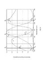
- FIG. 8 is a graph of a ROC curve for 52 data points/wavebands spectral data (top triangle symbol curve) and the ROC curve for a reduced number of data points of 18 wavebands (lower circular symbol curve);
- FIG. 9 is a flow chart illustrating an optimization procedure according to an example embodiment
- FIG. 10 is a graph showing an accuracy of three approaches of an optimization procedure of the present invention.
- FIG. 11 is a graph showing the effect of band width on the accuracy of an optimization procedure of the present invention.
- FIG. 12 is a flow chart illustrating a mapping algorithm according to an example embodiment
- FIG. 13 is a flow chart illustrating an intensity calibration algorithm according to an example embodiment which may be used to correct spectral images for measurement geometry variations
- FIG. 14 is a flow chart illustrating a rapid inversion algorithm according to an example embodiment which may be used for quantifying tissue physiological and morphological properties
- FIG. 14 a is a flow chart illustrating a rapid inversion algorithm according to another embodiment of the present invention.
- FIG. 15 is an illustration of resultant images such as may be obtained with an embodiment of a method and apparatus of the present invention.
- a multi-spectral imaging system provides parallel multi-band illumination and parallel multi-channel imaging detection to achieve high rate multi-spectral imaging.
- the imaging rate may be high enough to avoid motion artifacts.
- imaging is performed at video rates (e.g. 24 frames per second or more). Specular reflection may be automatically corrected for by a data analysis algorithm as described below.
- Such methods and apparatus may be used in combination with a multi-spectral imaging system or in other applications.
- the methods and apparatus may be employed, for example, in generating video rate or near video rate quantified images of the physical, physiological, and morphological properties of tissue.
- such methods and apparatus may be provided in a system that provides images indicating one or more of: tissue blood volume, tissue oxygenation, tissue scatter volume and tissue scatter size parameter.
- White light and/or fluorescence images may also be provided.
- Some embodiments provide a programmable multifunctional endoscopy system that can perform white light reflectance imaging (WLR), fluorescence imaging (FL) and multi-spectral reflectance imaging.
- WLR white light reflectance imaging
- FL fluorescence imaging
- multi-spectral reflectance imaging a programmable multifunctional endoscopy system that can perform white light reflectance imaging (WLR), fluorescence imaging (FL) and multi-spectral reflectance imaging.
- FIG. 1 is a block diagram showing functional elements of a programmable multifunctional endoscopy system 11 .
- System 11 comprises a light source 12 for generating illumination light comprising light in a plurality of narrow spectral bands and an optical camera/detector 7 for acquiring and generating spectral images corresponding to the spectral bands.
- the light emitted by light source 12 may consist essentially of light in the plurality of spectral bands. In some embodiments, at least 50% or at least 80% of the light energy in the illumination light emitted by light source 12 is in the plurality of spectral bands.
- light source 12 comprises a broadband light emitter 1 and an illumination light filter 2 for generating plurality of narrow spectral bands.
- Light filter 2 may, for example comprise a filter on a rotating filter wheel.
- Light emitter 1 may comprise, for example, a Xenon lamp which provides broad spectral illumination light in the wavelength range of 400-800 nm.
- light source 12 comprises a plurality of narrow-band light sources that each emit light in one of the plurality of spectral bands.
- light source 12 may comprise a plurality of light-emitting semiconductor devices (such as, for example light-emitting diodes LEDs).
- light source 12 is adapted to permit the spectral make up of the illumination light to be changed. For example, during a first period, light source 12 may emit light in a first set of narrow spectral bands, during a second period the light source 12 may emit light in a second set of narrow spectral bands different from the first set. This may be continued for a number of periods.
- light source 12 is configured to repeatedly cycle through a plurality of periods and, in each period, to emit illumination light in a plurality of spectral bands such that the spectrum of the illumination light (e.g. the specific spectral bands which make up the illumination light in that period) changes from period-to period.
- the illumination light emitted by light source 1 passes through filter 2 which filters out light that is outside of the plurality of narrow spectral bands to leave illumination light that is concentrated in the plurality of narrow spectral bands.
- Such illumination light is focused by a lens 3 into an illumination light guide 4 to irradiate a tissue 5 (an object being imaged).
- Light reflected by the tissue is captured by an imaging means which, in this example, comprises a collecting lens (not shown), an imaging light guide 6 and a detector 7 .
- Detector 7 may simultaneously acquire image data for each of the plurality of narrow spectral bands. This facilitates rapid acquisition of multi-spectral images.
- Detector 7 may comprise, for example, three charge-coupled devices (CCDs) such as a blue CCD responsive to light having wavelengths of 400-500 nm, a green CCD responsive to light having wavelengths in the range of 500-600 nm, and a red/NIR CCD responsive to light having wavelengths in the range of 600-800 nm.
- Detector 7 may further comprise a plurality of dichroic mirrors.
- a light beam from image guide 6 enters detector 7 and impinges onto a first dichroic mirror which reflects light having wavelengths smaller than 500 nm toward the blue CCD while transmitting light having wavelengths >500 nm.
- a second dichroic mirror reflects light having wavelengths smaller than 600 nm toward the green CCD and transmits light having wavelengths >600 nm toward the red/NIR CCD.
- detector 7 may comprise band pass filters in optical paths upstream from the CCDs (for example, one bandpass filter may be disposed in close proximity in front of each of the CCDs to further optically process the incident light.
- the CCDs may have exposure times shorter than video rate to accommodate fast image acquisition for multi-spectral imaging.
- Images obtained by the CCDs are processed by a processing unit 8 into plurality of spectral images.
- the obtained spectral images are then analyzed by the analyzing unit 9 and the resulted physiological and morphological images of the tissue are displayed on a desired output means such as a monitor 10 .
- Analyzing unit 9 may, for example, apply a modeling algorithm as described below.
- Light source 12 may provide visible and/or near infrared (NIR) radiation.
- NIR near infrared
- light source 12 may provide illumination light in the visible/NIR band extending from about 400 nm to at least about 800 nm.
- light source 12 has a mode of operation in which it emits broadband illumination in at least the visible range. Such a mode may be useful for generating images to guide an operator during an endoscopy procedure.
- detector 7 may capture an image that is similar to a conventional RGB image with the exception that the red channel covers e.g. 600-800 nm instead of a narrower range such as 600-700 nm.
- light source 12 can provide simultaneous multiple narrow band (NB) illumination (e.g. at 405 nm, 505 nm, and 605 nm).
- NB narrow band
- light source 12 can be quickly tuned to issue illumination light having a spectrum made up of the next multi-NB set (e.g.
- each multi-NB set has the same number of narrow band components as detector 7 has channels.
- each multi-NB set may comprise three narrow bands.
- filter wheel 2 may be used to generate illumination light in a sequence of periods such that in different periods the illumination light has a spectral make up that comprises different sets of three narrow bands.
- Filter wheel 2 may include more than one filter. When each of these filters is in the optical path between light emitter 1 and the object being imaged, the illumination light is made essentially of three narrow bands that are delivered simultaneously to the object.
- the bands may, for example, comprise one band in the blue part of the spectrum, one band in the green part of the spectrum and one band in the red or infrared part of the spectrum.
- filter 21 may generate illumination spectrum 26 during time period T 1 ; filter 22 generates illumination spectrum 27 during time period Ti; and filter 23 generates illumination spectrum 28 during time period Tn.
- the individual filters in filter wheel 2 can generate simultaneously more or fewer than three narrow wavebands.
- the filter wheel includes filters that provide a total of 12 to 52 different bands of illumination light with each filter providing two or three different bands.
- the number of narrow passbands for each filter is equal to or less than the number of channels provided by the detector in some embodiments.
- filter wheel 2 includes six filters providing a total of 18 bands of illumination light, three bands at a time.
- each filter provides a different spectral illumination profile comprised of a different set of three narrow bands of light.
- a table below shows one example of possible wavelengths of the 18 selected bands.
- the narrow bands have bandwidths of 20 nm or less.
- the 10 nm columns represent wavelength selections optimized for narrow bands having bandwidths of 10 nm.
- the 15 nm columns are wavelength selections optimized for the case where the narrow bands have bandwidths of 15 nm.
- the wavelengths of the narrow bands may be evenly or unevenly spaced apart.
- a first filter may provide simultaneously a light in a blue band (415 nm), green band (510 nm or 515 nm) and red band (610 nm or 615 nm).
- a second filter may provide illumination profile of 435 nm, 525 nm and 625 nm;
- a third filter may provide 445 nm or 450 nm, 540 nm or 545 nm and 640 nm or 645 nm;
- a forth filter may provide 460 nm or 465 nm, 560 nm and 665 nm;
- a fifth filter may provide 475 nm, 575 nm and 690 nm; and
- a sixth filter may provide 490 nm, 590 nm or 595 nm and 760 nm illumination light.
- FIG. 2 a An example transmission characteristic of a custom-made filter on filter wheel 2 is shown in FIG. 2 a . As shown this particular filter on the filter wheel 2 can pass simultaneously multiple bands of light in different wavelengths. In addition, a short wave pass filter can be used to remove the transmitted light above 800 nm.
- a filter wheel 2 switching between different spectral profiles is achieved by rotating the filter wheel 2 .
- the filter wheel 2 is rotated at a speed of about 30 r/s.
- Light from light emitter 1 may be used without narrow band filtering to provide white light illumination (e.g. 400-700 nm) for use in white light reflectance imaging. This may be achieved by providing one or more segments of filter wheel 2 which do not have narrow-band filters and/or providing a selectable optical path that bypasses filter wheel 2 .
- the light source 12 shown in FIG. 1 is only one example from among a large number of suitable light sources that may be applied for generating illumination having a spectrum comprising a plurality of narrow bands that can be imaged in the same exposure of detector 7 .
- an acousto-optic tunable filter (AOTF) based light source or a liquid crystal tunable filter (LCTF) based light source is used.
- a digital micromirror device (DMD) based spectrally programmable light source is used for providing effectively simultaneous multiple NB illumination.
- a light source comprises one or more acousto-optic tunable filters (AOTFs) for essentially simultaneous generation of multiple NB illumination.
- AOTFs acousto-optic tunable filters
- a model SC450-AOTF light source from Fianium, UK can generate light in which the spectrum has up to eight NB components.
- the AOTF can be used with a fiber laser based supercontinuum light source.
- light source 12 comprises a plurality of separate light emitters which each emit narrow band light in one or more specific wavelength bands.
- the light emitters may comprise light-emitting semiconductor devices such as light-emitting diodes (LEDs) for example.
- LEDs light-emitting diodes
- the light source comprises LEDs of several types with a plurality of LEDs of each type.
- a light source 12 is located at a distal end of an endoscope.
- a plurality of LEDs or LDs may be located at the distal end of the endoscope. This arrangement does not require a light guide 4 for carrying illumination light.
- the plurality of LEDs may be electronically switched at high rates to provide a plurality of illumination segments with specific spectral properties.
- the LEDs can be switched on and off electrically to conveniently achieve simultaneous multi-band illumination and be synchronized with the camera for corresponding image acquisition.
- the many LEDs may be arranged in a circle to achieve uniform illumination light at the tissue surface.
- FIG. 3 shows a distal end 30 of an endoscopy system with a plurality of LEDs 31 to generate light in a plurality of desired wavelength bands.
- the LEDs 31 may be mounted at the distal end of the endoscope surrounding a lens 32 , which can form an image at the imaging light guide 6 that in turn carries the image to detector 7 .
- a miniature camera 7 may be placed directly behind lens 32 , eliminating the need of imaging light guide 6 . This later set-up can also be used for open-field imaging applications, such as imaging of the human skin.
- a bandpass filter may optionally be deposited on the light-emitting face of each LED to help narrow down the spectral bandwidth to the desired specifications.
- the set of three LEDs 31 a may provide illumination light in three corresponding narrow bands (b a , g a , r a )
- the LEDs 31 b may provide illumination light in three corresponding narrow bands (b b , g b , r b ) at the same or different wavelength of LEDs 31 a
- LEDs 31 c may provide light in three narrow bands (b e , g e , r e ) at the same or different wavelength of LEDs 31 a and/or 31 b.
- FIG. 4 shows details of example image acquisition and processing electronics 8 .
- First image modes are selected and then the imaging signals are digitized by an A/D converter and sent to an Input FPGA (field programmable gate array) for processing.
- the digitized images are directed to an Input FIFO (first in first out) image buffer and then into a Programmable Logic and Processing Unit which can direct the images into either a WLR/FL (white light reflection/fluorescence) Frame buffer or a multi-spectral imaging buffer for further processing.
- the WLR images and the FL images may share the same buffer because these two imaging modalities are typically not performed simultaneously.
- a separate buffer with much larger memory is designated for multi-spectral imaging.
- the employment of two buffers also facilitates simultaneous WLR imaging and multi-spectral imaging if the light source is programmed to output the multi-NB illumination series and the WRL illumination in the same cycle.
- Various image processing functions may be implemented within the Input FPGA such as alignment of the three images taken by the red/near infrared (R/NIR), green (G) and blue (B) CCDs.
- tissue physiological and morphological parameters for each pixel producing at least four images, such as, e.g., tissue blood volume image, tissue oxygenation image, tissue scatter volume image, and tissue scatter size parameter image.
- additional images such as, e.g., an oxyhemoglobin image, a deoxyhemoglobin image, a tissue water volume image and/or an image of other chromophore distributions can be produced. Based on these images, a tissue diagnostic image may be generated that classifies each pixel as benign/normal or malignant.
- the processed digital images are output by an Output FIFO to an Output FPGA which exports various images into different Video Encoders (DACs) to transform the digital image signals into standard analog videos to be displayed on standard analog monitors.
- DACs Video Encoders
- the two image frame buffers can be connected to a PC computer, so that at any stage of the above mentioned process the digital images can be transferred into the PC for further processing and analyses and displaying the results on the computer monitors.
- the PC can be equipped with a GPU (Graphics Processing Unit) video processing card to speed up the image processing and data analysis.
- GPU Graphics Processing Unit
- detector 7 has four imaging CCDs such as B (400-500 nm), G (500-600 nm), R (600-700 nm), and NIR (700-800 nm).
- light source 12 may be adapted to generate illumination light in which the spectrum is made up of four narrow bands of light.
- the narrow bands may be within the B, G, R, and NIR bands respectively.
- the pass wavelength for the narrow bands may be controlled to change with time. This permits faster multi-spectral imaging to be performed.
- a white light reflectance image is synthesized from the acquired narrow-band spectral images.
- a reflectance spectrum can be generated so that a RGB color for the pixel can be obtained by multiplying the reflectance spectrum by an CIE (International Commission on Illumination) standard illumination spectrum to generate the radiance spectrum and convoluting the radiance spectrum with eye cone sensitivity spectra to generate the final R, G, B color quantities for display on a monitor for observing by the operator.
- CIE International Commission on Illumination
- a video endoscope has a detector (e.g. a CCD) installed at the tip of the endoscope.
- a detector e.g. a CCD
- an image light guide 6 is not required.
- the detector chip is coated with a I pattern of filters to facilitate three- or four channel imaging (B, G, R, NIR). A possible pattern is illustrated in the following table.
- a commercial color imaging detector e.g. CCD, CMOS or APS detector
- the detector may have filters applied in a Bayer filter mosaic to obtain R, G, B images.
- the filters in many commercially available imaging detectors can have spectral responses that overlap with one another f
- FIG. 5 shows example filter characteristics for filters of an example CCD image detector. The advantage of using this type of detector is reduced cost.
- a calibration procedure may be performed to obtain accurate reflectance signals corresponding to the individual narrow band illumination wavelengths.
- CCD output readings for each of the three image channels will have contributions from all the three wavelengths due to their overlapping spectral responses.
- the CCD blue channel reading can have contributions from the blue light as determined by the sensitivity T 11 , from the green light as determined by the sensitivity T 12 , and from the red light as determined by the sensitivity T 13 .
- C 2 T 21 I 1 +T 22 I 2 +T 23 I 3 (2)
- C 3 T 31 I 1 +T 32 I 2 +T 33 I 3 (3)
- a T matrix as illustrated in Equation (4) may be determined by performing a calibration. Calibration may be performed by illuminating the CCD with light I 1 , I 2 , and I 3 in separate exposures.
- I 1 can be measured by an optical power meter, while C 1 , C 2 , and C 3 are readings from the CCD's B, G, R channels respectively.
- T [ T 11 T 12 T 13 T 21 T 22 T 23 T 31 T 32 T 33 ] is a square matrix.
- snap-shot multi-spectral images of suspicious areas (which may be found, for example, by WLR imaging and/or FL imaging) can be captured for off-line analysis (or online but not fast enough to display the results in video rate) to derive snap-shot physiological and morphological images for diagnosis.
- the FL imaging illumination may be generated by a light source as shown in FIG. 7 .
- the FL imaging light source can provide illumination for FL imaging, while a programmable digital light source or a combination of a light emitter with a set of interchangeable filters (such as filters on a filter wheel) can provide illumination for WLR imaging and multi-spectral imaging.
- a programmable digital light source or a combination of a light emitter with a set of interchangeable filters such as filters on a filter wheel
- both the light source and the image acquisition and processing electronics are fully programmable.
- various ways of acquiring multi-spectral images e.g. different number of wavebands or different positions of these bands or different bandwidth
- WLR imaging as well as various image analysis algorithms can be implemented without changing the hardware.
- different numbers of wavebands can be used for multi-spectral imaging. Either evenly or non-evenly spaced wavebands may be selected. These wavebands can be programmed into the system to realize multi-spectral reflectance imaging.
- FIG. 8 shows a ROC curve for spectral data obtained from 52 data points/wavebands, (top triangle symbol curve) and an ROC curve when a reduced number of data points for 18 wavebands (lower circular symbol curve) is used.
- reducing the data points on each spectrum to 18 wavebands slightly reduces diagnostic accuracy but detection sensitivity and specificity remain reasonably good (80% and 77% respectively).
- a multi-spectral reflectance imaging system covering a reasonable number (e.g. 18+) wavebands, can provide superior accuracy comparing to the existing imaging endoscopy modalities, namely WLR mode and FL mode.
- Modeling and statistical approaches may be applied to determine the optimized wavelength bands for spectral imaging.
- a spectral analysis algorithm based on an optimized light-transport model is implemented in programmable image acquisition and processing electronics and a PC computer equipped with GPU for both real-time data processing and offline analysis.
- the minimum number of wavelengths and the optimum wavelength positions and band width are determined from empirical and/or simulated spectral measurements using optimization functions.
- One approach is based on numerical optimization (least-square) of an error function between an estimate obtained using the full spectrum and an estimate obtained using a spectrum that has been optimized for a reduced number of bands.
- FIG. 9 A flowchart illustrating an optimization procedure for obtaining optimum wavelength positions, Rn, for each given band number and given band width is shown in FIG. 9 .
- a selection of a number of wavelength bands (n), width, and position (Wt) are used to generate a corresponding spectrum.
- the generated spectrum is compared to full spectral measurements (Rref) using the optimization function.
- the process is repeated for another selection of number of wavelength and band width, the output of the optimization function is recorded and compared to determine the final selection.
- the analysis may be done assuming that the total number of bands and band width, for each of the three spectral detection channel of interest (Blue 400-500 nm, Green 500-600 nm, and Red/NIR 600-800 nm), are equal.
- the results of the above analysis may be used to generate graphs showing the relations between the number of wavelength bands, the band width, and the wavelength positions on the accuracies of the approximations.
- the generated graphs may be used for selecting the optimum design parameters (number of bands, their central wavelengths, and the band width) of the optical filters used in our spectral imaging device.
- FIG. 10 shows an example accuracy comparison of the three approaches of optimization procedure and
- FIG. 11 shows the effect of the band width on the accuracy.
- a mapping algorithm is used for obtaining a plurality of tissue physiological (absorption) properties related images and a plurality of tissue morphological (scattering) properties related images.
- the mapping algorithm may comprise two components: an intensity calibration algorithm and a rapid inversion algorithm.
- FIG. 12 shows a block diagram of an example mapping algorithm that may be applied for generating tissue physiological and morphological images at video-rate.
- the intensity calibration algorithm 200 can produce a corrected albedo spectral image 110 , a scattering spectral image 160 and an absorption spectral image 162 from the obtained spectral images 100 .
- the scattering spectral image 162 and the absorption spectral image 160 are then fed into the rapid inversion algorithm 300 to quantify the related tissue physiological and morphological properties 170 and 172 .
- the in-vitro absorption spectra 150 of the tissue is used together with the corrected albedo spectral image 110 to obtain corrected absorption and scattering images 160 , 162 .
- the intensity calibration algorithm 200 first generates the corrected albedo spectral images 110 , which are actually ratio of the absorption to the reduced scattering coefficients along the full spectral range.
- the corrected albedo spectral images 110 are then fed into the rapid inversion algorithm 300 to produce tissue physiological and morphological images 130 , 132 .
- physiological and morphological parameters 130 , 132 will have different accuracies from the physiological and morphological parameters 170 , 172 since they are generated with different modeling approaches.
- Intensity calibration algorithm 200 may be used to correct the intensity of the spectral images to account for measurement geometry variations such as, e.g., the variation in the coupling of reflected light from the tissue into the camera relative to the coupling of reflected light from a reflectance standard into the camera.
- two intensity calibration constants are defined and formulated: (1) a measurement geometry constant (Ka), which can correct for the coupling angle and measurement distance variation between the tissue and the camera during the measurements; and (2) an albedo correction constant (Ks), which corrects for the relative intensity nature of the measurements and allows for deducing both the absorption image and the scattering image from the albedo image using the in-vitro absorption spectra of the tissue being imaged as a priori known input to the calibration algorithm.
- Ka measurement geometry constant
- Ks an albedo correction constant
- R m and R c are the measured and corrected reflectance respectively; ⁇ c and ⁇ m are the corrected and measured albedo (ratio between the measured absorption and measured scattering coefficients) respectively; and ⁇ a c and ⁇ s′ c are the corrected absorption and scattering coefficients respectively.
- X[ ] is an inverse light transport model/function that relates the corrected ⁇ c albedo to the measured reflectance R m
- Y[ ] is a function that relates the absorption amplitude to the scattering amplitude.
- the exact shape or mathematical formulation of X and Y functions depend on the light transport model used in the analysis. A number of known light transport models such as, e.g., Monte Carlo, diffusion approximation model, etc., can be used with the intensity calibration algorithm described herein.
- the intensity calibration algorithm is applied along three wavelengths to produce corrected albedo spectral image or absorption spectral image and scattering spectral image in the full spectral imaging range.
- the physical meaning of the corrected absorption and/or scattering images means an image that is corrected from the reflectance intensity-related distortion/effect that resulted from the variation in the coupling of reflected light from tissue into camera relative to coupling of reflected light from reflectance standard into camera and relative to any movement of the light-camera probe (endoscope tip) orientation to tissue during measurements, which typically occurs during non-contact spectral reflectance measurements such as non-contact reflectance imaging.
- the algorithm can use in-vitro absorption spectra of the tissue being investigated as an a priori known parameter in order to generate the corrected absorption and scattering images along the full spectral imaging range.
- the fixed in-vitro absorption coefficient used in the intensity calibration algorithm acts as an internal tissue standard to allow for specifying and separating the scattering amplitude and the absorption amplitude. Consequently, it provides more robust quantitative data about tissue physiological and morphological properties.
- intensity calibration algorithm 200 uses three spectral images at wavelength ⁇ 1 , ⁇ 2 , ⁇ 3 ( 101 ), in-vitro absorption coefficients at ⁇ 1 , ⁇ 2 , ⁇ 3 ( 250 ) of the tissue being imaged, and randomly chosen initial values for measurement geometry constant Kai and albedo correction constant Ksi ( 201 ), as input parameters.
- the algorithm proceeds iteratively ( 240 and 242 ) until the calculated geometry constant Kac and the calculated albedo correction constant Ksc converge.
- the calculated albedo correction constant (Ksc) and geometry constant (Kac) can be used for producing in real time absorption spectral images 160 and scattering spectral images 162 , or corrected albedo spectral images 110 , respectively.
- the intensity calibration algorithm can be used with any light transport model such as diffusion approximation, a Monte Carlo generated look up table, or other light transport models.
- the calculated albedo correction constant (Ksc) and geometry constant (Kac) are used for producing in real time corrected absorption spectral images 162 and scattering spectral images 160 (arrowhead dash lined path 255 of FIG. 13 ).
- the intensity calibration algorithm generates only corrected albedo spectral images 110 , along the full spectral range without the use of any priori information.
- Rapid inversion algorithm 300 quantifies the related physiological and morphological properties 170 , 172 from the absorption and scattering spectral images 160 , 162 using linear matrix inversion scheme 350 , and intrinsic spectra of tissue absorption chromophores 310 and tissue scattering particles 312 , which are known standards.
- FIG. 14 a illustrates an alternative rapid inversion algorithm 300 .
- Rapid inversion algorithm 300 quantifies the related physiological and morphological properties 130 , 132 from the corrected albedo spectral images 110 using linear matrix inversion scheme 350 and intrinsic spectra of tissue absorption chromophores 310 and tissue scattering particles 312 .
- the physiological images/maps that are generated can include an oxygenated hemoglobin concentration image, a de-oxygenation hemoglobin image, a total hemoglobin concentration, and/or a tissue water volume image for example.
- the morphological images that can be generated can include a scattering volume image, a mucosa layer thickness image, and a specific scattering particles volume fraction (such as nucleus volume fraction).
- INV I c ⁇ ⁇ 1 ⁇ ( ⁇ 1 ) I c ⁇ ⁇ 1 ⁇ ( ⁇ 2 ) ⁇ I c ⁇ ⁇ 1 ⁇ ( ⁇ n ) I c ⁇ ⁇ 2 ⁇ ( ⁇ 1 ) I c ⁇ ⁇ 2 ⁇ ( ⁇ 2 ) ⁇ I c ⁇ ⁇ 2 ⁇ ( ⁇ n ) ⁇ ⁇ ⁇ ⁇ I cm ⁇ ( ⁇ 1 ) I cm ⁇ ( ⁇ 2 ) ⁇ I cm ⁇ ( ⁇ n ) ] ⁇ ⁇ ( ⁇ a ⁇ ⁇ c ( ⁇ 1 ) ⁇ a ⁇ ⁇ c ( ⁇ 2 ) ⁇ ⁇ a ⁇ ⁇ c ( ⁇ n ) )
- Cm is the m quantified physiological property
- I cm ( ⁇ n ) is the intrinsic spectra of the chromophor
- INV I s ⁇ ⁇ 1 ⁇ ( ⁇ 1 ) I s ⁇ ⁇ 1 ⁇ ( ⁇ 2 ) ⁇ I s ⁇ ⁇ 1 ⁇ ( ⁇ n ) I s ⁇ ⁇ 2 ⁇ ( ⁇ 1 ) I s ⁇ ⁇ 2 ⁇ ( ⁇ 2 ) ⁇ I s ⁇ ⁇ 2 ⁇ ( ⁇ n ) ⁇ ⁇ ⁇ ⁇ I sm ⁇ ( ⁇ 1 ) I sm ⁇ ( ⁇ 2 ) ⁇ I sm ⁇ ( ⁇ n ) ] ⁇ ⁇ ( ⁇ sc ′ ( ⁇ 1 ) ⁇ sc ′ ( ⁇ 2 ) ⁇ ⁇ sc ′ ( ⁇ n ) )
- I sm ( ⁇ n ) is the intrinsic spectra of the scattering particle m at ⁇ n .
- ⁇ sc( ⁇ n ) is the corrected scattering coefficient at A n .
- the mathematical formulation of I sm ( ⁇ n ) depends on the scattering particle model used to simulate the tissue scattering particles and components.
- the rapid inverse algorithm can take the absorption and/or scattering spectral images as inputs, and using the linear matrix inversion scheme and the intrinsic spectra of certain tissue chromophores and scattering particles, can generate a rapid mapping of certain physiological and/or morphological properties.
- FIG. 15 shows only one example of the resultant images such as, (a) oxygenation Image, (b) blood volume fraction image, (c) total scattering particles volume fraction image, and (d) detailed scattering particle volume fraction images (e.g. nucleus volume fraction), obtained during the rapid multispectral imaging.
- the obtained multiple physiological and morphological images can be used for cancer detection and localization and tumor margin delineation, which in turn will benefit to therapy planning and monitoring.
Landscapes
- Health & Medical Sciences (AREA)
- Life Sciences & Earth Sciences (AREA)
- Physics & Mathematics (AREA)
- Surgery (AREA)
- Engineering & Computer Science (AREA)
- General Health & Medical Sciences (AREA)
- Pathology (AREA)
- Medical Informatics (AREA)
- Heart & Thoracic Surgery (AREA)
- Veterinary Medicine (AREA)
- Public Health (AREA)
- Biophysics (AREA)
- Animal Behavior & Ethology (AREA)
- Optics & Photonics (AREA)
- Molecular Biology (AREA)
- Biomedical Technology (AREA)
- Nuclear Medicine, Radiotherapy & Molecular Imaging (AREA)
- Radiology & Medical Imaging (AREA)
- Spectroscopy & Molecular Physics (AREA)
- General Physics & Mathematics (AREA)
- Signal Processing (AREA)
- Multimedia (AREA)
- Microelectronics & Electronic Packaging (AREA)
- Chemical & Material Sciences (AREA)
- Analytical Chemistry (AREA)
- Biochemistry (AREA)
- Immunology (AREA)
- Evolutionary Computation (AREA)
- Artificial Intelligence (AREA)
- Endoscopes (AREA)
- Investigating Or Analysing Materials By Optical Means (AREA)
Priority Applications (1)
| Application Number | Priority Date | Filing Date | Title |
|---|---|---|---|
| US13/635,682 US9654745B2 (en) | 2010-03-17 | 2011-03-17 | Rapid multi-spectral imaging methods and apparatus and applications for cancer detection and localization |
Applications Claiming Priority (3)
| Application Number | Priority Date | Filing Date | Title |
|---|---|---|---|
| US31489310P | 2010-03-17 | 2010-03-17 | |
| US13/635,682 US9654745B2 (en) | 2010-03-17 | 2011-03-17 | Rapid multi-spectral imaging methods and apparatus and applications for cancer detection and localization |
| PCT/CA2011/050148 WO2011113162A1 (en) | 2010-03-17 | 2011-03-17 | Rapid multi-spectral imaging methods and apparatus and applications for cancer detection and localization |
Related Parent Applications (1)
| Application Number | Title | Priority Date | Filing Date |
|---|---|---|---|
| PCT/CA2011/050148 A-371-Of-International WO2011113162A1 (en) | 2010-03-17 | 2011-03-17 | Rapid multi-spectral imaging methods and apparatus and applications for cancer detection and localization |
Related Child Applications (1)
| Application Number | Title | Priority Date | Filing Date |
|---|---|---|---|
| US15/485,132 Continuation US20170223316A1 (en) | 2010-03-17 | 2017-04-11 | Rapid multi-spectral imaging methods and apparatus and applications for cancer detection and localization |
Publications (2)
| Publication Number | Publication Date |
|---|---|
| US20130012794A1 US20130012794A1 (en) | 2013-01-10 |
| US9654745B2 true US9654745B2 (en) | 2017-05-16 |
Family
ID=44648397
Family Applications (2)
| Application Number | Title | Priority Date | Filing Date |
|---|---|---|---|
| US13/635,682 Active 2033-04-13 US9654745B2 (en) | 2010-03-17 | 2011-03-17 | Rapid multi-spectral imaging methods and apparatus and applications for cancer detection and localization |
| US15/485,132 Abandoned US20170223316A1 (en) | 2010-03-17 | 2017-04-11 | Rapid multi-spectral imaging methods and apparatus and applications for cancer detection and localization |
Family Applications After (1)
| Application Number | Title | Priority Date | Filing Date |
|---|---|---|---|
| US15/485,132 Abandoned US20170223316A1 (en) | 2010-03-17 | 2017-04-11 | Rapid multi-spectral imaging methods and apparatus and applications for cancer detection and localization |
Country Status (9)
| Country | Link |
|---|---|
| US (2) | US9654745B2 (enExample) |
| EP (1) | EP2547992A4 (enExample) |
| JP (1) | JP2013521900A (enExample) |
| CN (1) | CN102893137B (enExample) |
| AU (1) | AU2011229113A1 (enExample) |
| BR (1) | BR112012023287A2 (enExample) |
| CA (1) | CA2793449A1 (enExample) |
| RU (1) | RU2012143821A (enExample) |
| WO (1) | WO2011113162A1 (enExample) |
Cited By (6)
| Publication number | Priority date | Publication date | Assignee | Title |
|---|---|---|---|---|
| US10345237B1 (en) | 2019-01-31 | 2019-07-09 | Rarecyte, Inc. | Spectral edge detection |
| US10753875B1 (en) | 2019-01-31 | 2020-08-25 | Rarecyte, Inc. | Spectral unmixing of spectroscopic emission images |
| US10846917B2 (en) | 2019-01-03 | 2020-11-24 | Microsoft Technology Licensing, Llc | Iterating different camera representations in three-dimensional model |
| US20210392302A1 (en) * | 2020-06-11 | 2021-12-16 | Viavi Solutions Inc. | Scrolling spectral filter |
| US20240023811A1 (en) * | 2022-07-20 | 2024-01-25 | California Institute Of Technology | Systems for Biomarker Detection and Methods Thereof |
| US12089805B2 (en) * | 2017-10-17 | 2024-09-17 | Fujifilm Corporation | Medical image processing apparatus and endoscope apparatus |
Families Citing this family (143)
| Publication number | Priority date | Publication date | Assignee | Title |
|---|---|---|---|---|
| US10568535B2 (en) | 2008-05-22 | 2020-02-25 | The Trustees Of Dartmouth College | Surgical navigation with stereovision and associated methods |
| WO2013109966A1 (en) | 2012-01-20 | 2013-07-25 | The Trustees Of Dartmouth College | Method and apparatus for quantitative hyperspectral fluorescence and reflectance imaging for surgical guidance |
| US9101287B2 (en) | 2011-03-07 | 2015-08-11 | Endochoice Innovation Center Ltd. | Multi camera endoscope assembly having multiple working channels |
| US11864734B2 (en) | 2009-06-18 | 2024-01-09 | Endochoice, Inc. | Multi-camera endoscope |
| US9706903B2 (en) | 2009-06-18 | 2017-07-18 | Endochoice, Inc. | Multiple viewing elements endoscope system with modular imaging units |
| US9101268B2 (en) | 2009-06-18 | 2015-08-11 | Endochoice Innovation Center Ltd. | Multi-camera endoscope |
| US9713417B2 (en) | 2009-06-18 | 2017-07-25 | Endochoice, Inc. | Image capture assembly for use in a multi-viewing elements endoscope |
| US11278190B2 (en) | 2009-06-18 | 2022-03-22 | Endochoice, Inc. | Multi-viewing element endoscope |
| US9642513B2 (en) | 2009-06-18 | 2017-05-09 | Endochoice Inc. | Compact multi-viewing element endoscope system |
| US10165929B2 (en) | 2009-06-18 | 2019-01-01 | Endochoice, Inc. | Compact multi-viewing element endoscope system |
| US9901244B2 (en) | 2009-06-18 | 2018-02-27 | Endochoice, Inc. | Circuit board assembly of a multiple viewing elements endoscope |
| US8926502B2 (en) | 2011-03-07 | 2015-01-06 | Endochoice, Inc. | Multi camera endoscope having a side service channel |
| US12137873B2 (en) | 2009-06-18 | 2024-11-12 | Endochoice, Inc. | Compact multi-viewing element endoscope system |
| US9872609B2 (en) | 2009-06-18 | 2018-01-23 | Endochoice Innovation Center Ltd. | Multi-camera endoscope |
| US9402533B2 (en) | 2011-03-07 | 2016-08-02 | Endochoice Innovation Center Ltd. | Endoscope circuit board assembly |
| US11547275B2 (en) | 2009-06-18 | 2023-01-10 | Endochoice, Inc. | Compact multi-viewing element endoscope system |
| CA2765559C (en) | 2009-06-18 | 2017-09-05 | Peer Medical Ltd. | Multi-camera endoscope |
| US9492063B2 (en) | 2009-06-18 | 2016-11-15 | Endochoice Innovation Center Ltd. | Multi-viewing element endoscope |
| JP5597021B2 (ja) * | 2010-04-15 | 2014-10-01 | オリンパス株式会社 | 画像処理装置及びプログラム |
| US12220105B2 (en) | 2010-06-16 | 2025-02-11 | Endochoice, Inc. | Circuit board assembly of a multiple viewing elements endoscope |
| US9277855B2 (en) * | 2010-08-10 | 2016-03-08 | Boston Scientific Scimed, Inc. | Endoscopic system for enhanced visualization |
| US9560953B2 (en) | 2010-09-20 | 2017-02-07 | Endochoice, Inc. | Operational interface in a multi-viewing element endoscope |
| US10080486B2 (en) | 2010-09-20 | 2018-09-25 | Endochoice Innovation Center Ltd. | Multi-camera endoscope having fluid channels |
| EP3540495A1 (en) | 2010-10-28 | 2019-09-18 | EndoChoice Innovation Center Ltd. | Optical systems for multi-sensor endoscopes |
| US12204087B2 (en) | 2010-10-28 | 2025-01-21 | Endochoice, Inc. | Optical systems for multi-sensor endoscopes |
| CN107361721B (zh) | 2010-12-09 | 2019-06-18 | 恩多巧爱思创新中心有限公司 | 用于多摄像头内窥镜的柔性电子电路板 |
| EP3420886B8 (en) | 2010-12-09 | 2020-07-15 | EndoChoice, Inc. | Flexible electronic circuit board multi-camera endoscope |
| US11889986B2 (en) | 2010-12-09 | 2024-02-06 | Endochoice, Inc. | Flexible electronic circuit board for a multi-camera endoscope |
| US9101266B2 (en) | 2011-02-07 | 2015-08-11 | Endochoice Innovation Center Ltd. | Multi-element cover for a multi-camera endoscope |
| JP2012217673A (ja) * | 2011-04-11 | 2012-11-12 | Fujifilm Corp | 内視鏡診断装置 |
| US9014789B2 (en) | 2011-09-22 | 2015-04-21 | The George Washington University | Systems and methods for visualizing ablated tissue |
| WO2013044182A1 (en) | 2011-09-22 | 2013-03-28 | The George Washington University | Systems and methods for visualizing ablated tissue |
| JP5789232B2 (ja) * | 2011-10-12 | 2015-10-07 | 富士フイルム株式会社 | 内視鏡システム及びその作動方法 |
| EP2604172B1 (en) | 2011-12-13 | 2015-08-12 | EndoChoice Innovation Center Ltd. | Rotatable connector for an endoscope |
| EP2604175B1 (en) | 2011-12-13 | 2019-11-20 | EndoChoice Innovation Center Ltd. | Removable tip endoscope |
| US11813100B2 (en) | 2012-01-04 | 2023-11-14 | The Trustees Of Dartmouth College | Methods for quantitative and enhanced-contrast molecular medical imaging using cross-modality correction for differing tracer kinetics |
| WO2014127145A1 (en) | 2013-02-13 | 2014-08-21 | The Trustees Of Dartmouth College | Method and apparatus for medical imaging using differencing of multiple fluorophores |
| US11510600B2 (en) | 2012-01-04 | 2022-11-29 | The Trustees Of Dartmouth College | Method and apparatus for quantitative and depth resolved hyperspectral fluorescence and reflectance imaging for surgical guidance |
| US12061328B2 (en) | 2012-01-20 | 2024-08-13 | The Trustees Of Dartmouth College | Method and apparatus for quantitative hyperspectral fluorescence and reflectance imaging for surgical guidance |
| CN103385693A (zh) * | 2012-05-09 | 2013-11-13 | 朱瑞龙 | 一种肿瘤成像装置 |
| CN102721469B (zh) * | 2012-06-14 | 2015-05-13 | 中国科学院自动化研究所 | 双相机的多光谱成像系统和方法 |
| US9560954B2 (en) | 2012-07-24 | 2017-02-07 | Endochoice, Inc. | Connector for use with endoscope |
| CN102809429A (zh) * | 2012-07-26 | 2012-12-05 | 中国科学院自动化研究所 | 基于双相机的多光谱成像系统和方法 |
| WO2014036470A1 (en) | 2012-08-31 | 2014-03-06 | Sloan-Kettering Institute For Cancer Research | Particles, methods and uses thereof |
| JP6465811B2 (ja) | 2012-12-19 | 2019-02-06 | スローン − ケタリング・インスティテュート・フォー・キャンサー・リサーチ | 多様式の粒子、方法およびその使用 |
| CN105102945B (zh) * | 2013-01-10 | 2018-07-10 | 加利珀生命科学股份有限公司 | 多光谱成像系统和方法 |
| CN105103190B (zh) * | 2013-01-10 | 2018-07-17 | 加利珀生命科学股份有限公司 | 全视野载玻片多光谱成像系统和方法 |
| EP2951301A4 (en) * | 2013-02-01 | 2016-11-02 | Daniel Farkas | METHOD AND SYSTEM FOR CHARACTERIZING THREE-DIMENSIONAL FABRIC USING MULTIMODAL OPTICAL MEASUREMENTS |
| JP6157135B2 (ja) * | 2013-02-07 | 2017-07-05 | オリンパス株式会社 | 光源撮像装置 |
| US11937951B2 (en) | 2013-02-13 | 2024-03-26 | The Trustees Of Dartmouth College | Method and apparatus for medical imaging using differencing of multiple fluorophores |
| US10213111B2 (en) * | 2013-02-14 | 2019-02-26 | Bc Cancer, Part Of The Provincial Health Services Authority | Method and apparatus for optical measurements under ambient light conditions |
| US20140350534A1 (en) * | 2013-02-20 | 2014-11-27 | Sloan-Kettering Institute For Cancer Research | Raman based ablation/resection systems and methods |
| AU2014218867B2 (en) | 2013-02-20 | 2018-11-08 | Sloan-Kettering Institute For Cancer Research | Wide field raman imaging apparatus and associated methods |
| US9986899B2 (en) | 2013-03-28 | 2018-06-05 | Endochoice, Inc. | Manifold for a multiple viewing elements endoscope |
| US9993142B2 (en) | 2013-03-28 | 2018-06-12 | Endochoice, Inc. | Fluid distribution device for a multiple viewing elements endoscope |
| US10499794B2 (en) | 2013-05-09 | 2019-12-10 | Endochoice, Inc. | Operational interface in a multi-viewing element endoscope |
| CN103284681A (zh) * | 2013-05-24 | 2013-09-11 | 中国科学院苏州生物医学工程技术研究所 | 一种血管内双光谱成像装置 |
| WO2015002311A1 (ja) * | 2013-07-05 | 2015-01-08 | オリンパスメディカルシステムズ株式会社 | 医療表示装置および内視鏡手術システム |
| CN103356154B (zh) * | 2013-07-15 | 2016-07-06 | 中国人民解放军第二军医大学 | 一种适用于消化道内的多功能胶囊内窥镜系统 |
| CN103356152B (zh) * | 2013-07-15 | 2016-07-06 | 中国人民解放军第二军医大学 | 含便携式定位装置的胶囊内窥镜系统 |
| KR101537854B1 (ko) * | 2013-09-23 | 2015-07-21 | 에스엔유 프리시젼 주식회사 | 두께 측정 장치 및 이를 이용한 두께 측정 방법 |
| JP2015077335A (ja) * | 2013-10-18 | 2015-04-23 | 三菱電機エンジニアリング株式会社 | 光源装置 |
| US10080504B2 (en) | 2013-11-08 | 2018-09-25 | University Of Houston System | Imaging system for intra-operative and post-operative blood perfusion monitoring |
| WO2015073871A2 (en) | 2013-11-14 | 2015-05-21 | The George Washington University | Systems and methods for determining lesion depth using fluorescence imaging |
| WO2015077474A1 (en) | 2013-11-20 | 2015-05-28 | The George Washington University | Systems and methods for hyperspectral analysis of cardiac tissue |
| JP6471942B2 (ja) * | 2013-11-29 | 2019-02-20 | 国立大学法人 東京大学 | 画像処理装置、画像処理方法及び記録媒体 |
| US20170164837A1 (en) * | 2014-02-11 | 2017-06-15 | The Florida International University Board Of Trustees | Intraoperative guidance system for tumor surgery |
| US10912947B2 (en) | 2014-03-04 | 2021-02-09 | Memorial Sloan Kettering Cancer Center | Systems and methods for treatment of disease via application of mechanical force by controlled rotation of nanoparticles inside cells |
| CN106461462B (zh) * | 2014-03-21 | 2019-03-26 | 海佩尔梅德影像有限公司 | 紧凑型光传感器 |
| WO2015156153A1 (ja) * | 2014-04-08 | 2015-10-15 | オリンパス株式会社 | 蛍光観察内視鏡システム |
| JP6728070B2 (ja) * | 2014-06-05 | 2020-07-22 | ウニベルジテート ハイデルベルク | マルチスペクトルイメージングのための方法及び手段 |
| US9968285B2 (en) * | 2014-07-25 | 2018-05-15 | Christie Digital Systems Usa, Inc. | Multispectral medical imaging devices and methods thereof |
| WO2016018896A1 (en) | 2014-07-28 | 2016-02-04 | Memorial Sloan Kettering Cancer Center | Metal(loid) chalcogen nanoparticles as universal binders for medical isotopes |
| WO2016056015A1 (en) * | 2014-10-08 | 2016-04-14 | Collage Medical Imaging Ltd. | Synchronized dual mode oct system |
| CN104116482B (zh) * | 2014-08-11 | 2016-05-18 | 福建师范大学 | 一种基于内窥镜的光学图像和光谱信号检测装置 |
| JP6204314B2 (ja) * | 2014-09-03 | 2017-09-27 | Hoya株式会社 | 電子内視鏡システム |
| ES2569550A1 (es) * | 2014-10-10 | 2016-05-11 | Consejo Superior De Investigaciones Científicas (Csic) | Espectrofotómetro |
| US10143517B2 (en) | 2014-11-03 | 2018-12-04 | LuxCath, LLC | Systems and methods for assessment of contact quality |
| US10722301B2 (en) | 2014-11-03 | 2020-07-28 | The George Washington University | Systems and methods for lesion assessment |
| RU2601678C2 (ru) * | 2014-12-15 | 2016-11-10 | Самсунг Электроникс Ко., Лтд. | Портативное устройство для измерения хромофоров в коже и способ применения устройства |
| CN104434013A (zh) * | 2014-12-24 | 2015-03-25 | 中国科学技术大学 | 一种多模态阴道镜系统及获取多模态图像的方法 |
| KR101650319B1 (ko) * | 2015-03-06 | 2016-08-24 | 에스엔유 프리시젼 주식회사 | 컬러 카메라를 이용한 두께 측정방법 및 두께 측정장치 |
| CN107405056B (zh) * | 2015-03-17 | 2020-06-30 | 奥林巴斯株式会社 | 活体观察系统 |
| CN104887321A (zh) * | 2015-05-08 | 2015-09-09 | 安徽信美医学工程科技有限公司 | 一种便携多模式医疗显微导航装置及其控制方法 |
| JP6609220B2 (ja) * | 2015-06-01 | 2019-11-20 | マハジャン ニティン | マルチモダリティ医療用可撓性ビデオ内視鏡 |
| CN106256313B (zh) * | 2015-06-17 | 2021-02-05 | 松下知识产权经营株式会社 | 摄像装置 |
| JP2018126174A (ja) * | 2015-06-17 | 2018-08-16 | オリンパス株式会社 | 内視鏡装置 |
| WO2017004301A1 (en) | 2015-07-01 | 2017-01-05 | Memorial Sloan Kettering Cancer Center | Anisotropic particles, methods and uses thereof |
| US10779904B2 (en) | 2015-07-19 | 2020-09-22 | 460Medical, Inc. | Systems and methods for lesion formation and assessment |
| US9903757B1 (en) * | 2015-09-25 | 2018-02-27 | Hrl Laboratories, Llc | Active multi-spectral sensor |
| WO2017122431A1 (ja) * | 2016-01-15 | 2017-07-20 | オリンパス株式会社 | 画像解析装置、画像解析システム、及び画像解析装置の作動方法 |
| US10295462B1 (en) | 2016-03-02 | 2019-05-21 | Hrl Laboratories, Llc | Detection by active spatially and spectrally structured sensing and learning (DAS4L) |
| JP6561000B2 (ja) * | 2016-03-09 | 2019-08-14 | 富士フイルム株式会社 | 内視鏡システム及びその作動方法 |
| WO2017158078A1 (en) * | 2016-03-16 | 2017-09-21 | INSERM (Institut National de la Santé et de la Recherche Médicale) | Endoscope and method for exploring a peritoneum |
| JPWO2017168477A1 (ja) * | 2016-03-28 | 2019-02-07 | パナソニックIpマネジメント株式会社 | 撮像装置および画像処理方法 |
| EP3257432B1 (en) * | 2016-06-17 | 2023-05-10 | FUJIFILM Corporation | Light source device and endoscope system |
| CN109310270B (zh) * | 2016-07-05 | 2021-03-19 | 奥林巴斯株式会社 | 具有多个窄带光源的照明装置 |
| US10401610B2 (en) | 2016-07-15 | 2019-09-03 | Canon Usa, Inc. | Spectrally encoded probe with multiple diffraction orders |
| EP3504590B1 (en) | 2016-08-24 | 2025-07-23 | Mimosa Diagnostics Inc. | Multispectral mobile tissue assessment |
| US10834377B2 (en) * | 2016-08-29 | 2020-11-10 | Faro Technologies, Inc. | Forensic three-dimensional measurement device |
| WO2018068004A1 (en) * | 2016-10-07 | 2018-04-12 | Baylor Research Institute | Classification of polyps using learned image analysis |
| DE102016119730A1 (de) * | 2016-10-17 | 2018-04-19 | Carl Zeiss Microscopy Gmbh | Optikgruppe für Detektionslicht für ein Mikroskop, Verfahren zur Mikroskopie und Mikroskop |
| US10898068B2 (en) | 2016-11-01 | 2021-01-26 | Canon U.S.A., Inc. | Multi-bandwidth spectrally encoded endoscope |
| WO2018102467A1 (en) * | 2016-11-29 | 2018-06-07 | Anasys Instruments Corporation | Method and apparatus for enhanced photo-thermal imaging and spectroscopy |
| DE102016125524A1 (de) * | 2016-12-22 | 2018-06-28 | Arnold & Richter Cine Technik Gmbh & Co. Betriebs Kg | Elektronisches Mikroskop |
| WO2018202270A1 (en) * | 2017-05-04 | 2018-11-08 | Nkt Photonics A/S | Light system for supplying light |
| CN108937849A (zh) * | 2017-05-29 | 2018-12-07 | 王虎 | 一种用于肿瘤纳米靶向探针荧光成像及手术导航指示系统 |
| US11333553B2 (en) | 2017-07-19 | 2022-05-17 | Siemens Healthcare Diagnostics Inc. | Methods and apparatus for specimen characterization using hyperspectral imaging |
| WO2019045971A1 (en) | 2017-08-28 | 2019-03-07 | East Carolina University | MULTI-SPECTRAL PHYSIOLOGICAL VISUALIZATION (MSPV) USING LASER IMAGING METHODS AND SYSTEMS TO PERFORM IMAGING AND QUANTIFICATION OF BLOOD FLOW AND INFUSION IN ENDOSCOPIC DESIGN |
| WO2019051591A1 (en) * | 2017-09-15 | 2019-03-21 | Kent Imaging | VISIBLE AND INFRARED HYBRID IMAGING WITH A RGB COLOR FILTER NETWORK SENSOR |
| CN107764750B (zh) * | 2017-10-18 | 2021-03-16 | 西安鹿谱工控有限公司 | 一种非接触式色度检测装置及检测方法 |
| CN108181642B (zh) * | 2017-11-27 | 2020-08-21 | 中核控制系统工程有限公司 | 一种基于GPU和奇异值方法的γ谱仪谱分析方法 |
| DE102018108809B4 (de) * | 2018-04-13 | 2020-02-06 | Hensoldt Optronics Gmbh | Kamerasystem |
| EP3801211A1 (en) | 2018-06-08 | 2021-04-14 | East Carolina University | Determining peripheral oxygen saturation (spo2) and hemoglobin concentration using multi-spectral laser imaging (msli) methods and systems |
| US10948350B2 (en) | 2018-09-05 | 2021-03-16 | East Carolina University | Systems for detecting vascular and arterial disease in asymptomatic patients and related methods |
| US10982836B2 (en) | 2018-10-31 | 2021-04-20 | Microsoft Technology Licensing, Llc | Tunable spectral illuminator for camera |
| US10931894B2 (en) | 2018-10-31 | 2021-02-23 | Microsoft Technology Licensing, Llc | Tunable spectral illuminator for camera |
| CN109269643B (zh) * | 2018-11-02 | 2021-05-11 | 天津津航技术物理研究所 | 基于移动设备屏幕光源的光谱解调系统及方法 |
| CN109855735A (zh) * | 2019-02-20 | 2019-06-07 | 北京理工大学 | 一种同步控制与采集的高光谱计算成像方法 |
| US20200288965A1 (en) * | 2019-03-11 | 2020-09-17 | Spring Biomed Vision Ltd. | System and method for enhanced imaging of biological tissue |
| US20200294228A1 (en) * | 2019-03-13 | 2020-09-17 | East Carolina University | Non-Contact Multispectral Imaging for Blood Oxygen Level and Perfusion Measurement and Related Systems and Computer Program Products |
| EP3945986A1 (en) | 2019-03-26 | 2022-02-09 | East Carolina University | Near-infrared fluorescence imaging for blood flow and perfusion visualization and related systems and computer program products |
| CN110057824B (zh) * | 2019-05-06 | 2024-05-14 | 中国科学院海洋研究所 | 一种海洋浮游生物光学成像装置及成像处理方法 |
| US11712155B2 (en) | 2019-06-20 | 2023-08-01 | Cilag GmbH Intenational | Fluorescence videostroboscopy of vocal cords |
| EP3805838B1 (en) * | 2019-10-10 | 2023-12-06 | Leica Instruments (Singapore) Pte. Ltd. | Microscope and related apparatuses, methods and computer programs |
| US11911152B2 (en) | 2019-10-29 | 2024-02-27 | Samsung Electronics Co., Ltd. | Apparatus and method for estimating concentration of analyte, and calibration method |
| DE102019217541A1 (de) * | 2019-11-13 | 2021-05-20 | Fraunhofer-Gesellschaft zur Förderung der angewandten Forschung e.V. | Medizinische Bildgebungseinrichtung, Verfahren und Verwendung |
| CN110833399B (zh) * | 2019-11-29 | 2021-08-13 | 中国科学院自动化研究所 | 近红外二区单通道分时复用成像系统及其使用方法 |
| KR20220104817A (ko) * | 2019-12-04 | 2022-07-26 | 켐이미지 코포레이션 | 튜닝 가능한 발광 다이오드 소스의 현장 최적화를 위한 시스템 및 방법 |
| CN115103647A (zh) | 2020-01-08 | 2022-09-23 | 460医学股份有限公司 | 用于消融损伤的光学询问的系统和方法 |
| WO2021226493A1 (en) * | 2020-05-08 | 2021-11-11 | The Regents Of The University Of California | Label-free real-time hyperspectral endoscopy for molecular-guided cancer surgery |
| WO2021236615A1 (en) * | 2020-05-18 | 2021-11-25 | Chemimage Corporation | Systems and methods for detecting oral cancer using molecular chemical imaging |
| WO2022020989A1 (zh) * | 2020-07-27 | 2022-02-03 | 华为技术有限公司 | 一种滤光阵列、移动终端以及设备 |
| CN114376491B (zh) * | 2020-10-16 | 2025-09-02 | 舜宇光学(浙江)研究院有限公司 | 内窥镜成像装置及其方法、系统以及电子设备 |
| CN114449137B (zh) * | 2020-11-02 | 2025-06-13 | 北京小米移动软件有限公司 | 滤光片结构、拍摄方法、装置、终端及存储介质 |
| EP4314739A4 (en) * | 2021-03-30 | 2025-02-19 | Spectral MD, Inc. | SYSTEM AND METHOD FOR MULTISPECTRAL IMAGING WITH HIGH-PRECISION SNAPSHOT BASED ON MULTIPLEXED ILLUMINATION |
| DE102021118559A1 (de) * | 2021-07-19 | 2023-01-19 | Senorics Gmbh | Verfahren und System zur Analyse einer Probe anhand von Daten |
| CN114034642B (zh) * | 2021-12-08 | 2023-10-24 | 重庆大学 | 基于微环谐振阵列的拉曼光谱片上检测系统及方法 |
| CN114532987B (zh) * | 2022-02-16 | 2023-12-19 | 北京市神经外科研究所 | 基于拉曼光谱的信息处理方法、装置及存储介质 |
| CN119234248A (zh) * | 2022-05-17 | 2024-12-31 | 捷锐士阿希迈公司(以奥林巴斯美国外科技术名义) | 用于同时运行离散成像模态的技术 |
| US20240122461A1 (en) * | 2022-10-13 | 2024-04-18 | Omnivision Technologies, Inc. | Multi-band imaging for endoscopes |
| US20240231072A9 (en) * | 2022-10-21 | 2024-07-11 | Karl Storz Imaging, Inc. | Imaging Device Including Two Image Sensors Enabling Multiple Imaging Modes and Associated Imaging Systems |
| CN120264121B (zh) * | 2025-06-06 | 2025-11-07 | 北京博视像元科技有限公司 | 一种基于分光棱镜与多通道tdi芯片融合的高速多光谱相机 |
Citations (30)
| Publication number | Priority date | Publication date | Assignee | Title |
|---|---|---|---|---|
| US5749830A (en) * | 1993-12-03 | 1998-05-12 | Olympus Optical Co., Ltd. | Fluorescent endoscope apparatus |
| US5796512A (en) | 1996-02-16 | 1998-08-18 | Carnegie Mellon University | Subicron imaging system having an acousto-optic tunable filter |
| US6061591A (en) | 1996-03-29 | 2000-05-09 | Richard Wolf Gmbh | Arrangement and method for diagnosing malignant tissue by fluorescence observation |
| US6069689A (en) * | 1997-04-16 | 2000-05-30 | Derma Technologies, Inc. | Apparatus and methods relating to optical systems for diagnosis of skin diseases |
| US6081612A (en) | 1997-02-28 | 2000-06-27 | Electro Optical Sciences Inc. | Systems and methods for the multispectral imaging and characterization of skin tissue |
| US20020103439A1 (en) * | 2000-12-19 | 2002-08-01 | Haishan Zeng | Methods and apparatus for fluorescence and reflectance imaging and spectroscopy and for contemporaneous measurements of electromagnetic radiation with multiple measuring devices |
| US6678398B2 (en) | 2000-09-18 | 2004-01-13 | Sti Medical Systems, Inc. | Dual mode real-time screening and rapid full-area, selective-spectral, remote imaging and analysis device and process |
| US6697652B2 (en) * | 2001-01-19 | 2004-02-24 | Massachusetts Institute Of Technology | Fluorescence, reflectance and light scattering spectroscopy for measuring tissue |
| US20040225222A1 (en) | 2003-05-08 | 2004-11-11 | Haishan Zeng | Real-time contemporaneous multimodal imaging and spectroscopy uses thereof |
| US20040245350A1 (en) * | 2003-06-03 | 2004-12-09 | Haishan Zeng | Methods and apparatus for fluorescence imaging using multiple excitation-emission pairs and simultaneous multi-channel image detection |
| US20050059894A1 (en) * | 2003-09-16 | 2005-03-17 | Haishan Zeng | Automated endoscopy device, diagnostic method, and uses |
| EP1528380A1 (en) | 2002-07-26 | 2005-05-04 | Olympus Corporation | Image processing system |
| WO2005088264A1 (en) | 2004-03-06 | 2005-09-22 | Plain Sight Systems, Inc. | Hyper-spectral imaging methods and devices |
| US20060264760A1 (en) * | 2005-02-10 | 2006-11-23 | Board Of Regents, The University Of Texas System | Near infrared transrectal probes for prostate cancer detection and prognosis |
| US20070024946A1 (en) | 2004-12-28 | 2007-02-01 | Panasyuk Svetlana V | Hyperspectral/multispectral imaging in determination, assessment and monitoring of systemic physiology and shock |
| US20070167836A1 (en) * | 2005-07-25 | 2007-07-19 | Massachusetts Institute Of Technology | Multi modal spectroscopy |
| US7321791B2 (en) * | 2003-09-23 | 2008-01-22 | Cambridge Research And Instrumentation, Inc. | Spectral imaging of deep tissue |
| JP2008036035A (ja) | 2006-08-03 | 2008-02-21 | Olympus Medical Systems Corp | 内視鏡装置 |
| US20080208006A1 (en) | 2004-09-24 | 2008-08-28 | Mina Farr | Opto-electronic illumination and vision module for endoscopy |
| JP2008283692A (ja) | 2002-07-26 | 2008-11-20 | Olympus Corp | 撮影装置、画像処理システム |
| US20090023991A1 (en) | 2005-05-12 | 2009-01-22 | Olympus Medical Systems Corp. | Biological observation apparatus |
| WO2009018849A1 (de) | 2007-08-09 | 2009-02-12 | Siemens Aktiengesellschaft | Anordnung zur bildaufnahme von elementen |
| WO2009052607A1 (en) | 2007-10-24 | 2009-04-30 | Perceptronix Medical Inc. | Method and apparatus for microvascular oxygenation imaging |
| US20090137908A1 (en) | 2007-11-26 | 2009-05-28 | Patwardhan Sachin V | Multi-spectral tissue imaging |
| US20090225156A1 (en) * | 2008-03-10 | 2009-09-10 | Olympus Medical Systems Corp. | Endoscope observation system |
| US20090270702A1 (en) | 2005-01-21 | 2009-10-29 | Haishan Zeng | Method and apparatus for measuring cancerous changes from reflectance spectral measurements obtained during endoscopic imaging |
| US20100033986A1 (en) | 2008-08-05 | 2010-02-11 | Perceptron Inc. | Light Pipe For Imaging Head of Video Inspection Device |
| US20100056928A1 (en) | 2008-08-10 | 2010-03-04 | Karel Zuzak | Digital light processing hyperspectral imaging apparatus |
| US7729751B2 (en) | 2005-09-30 | 2010-06-01 | Fujinon Corporation | Electronic endoscopic apparatus |
| EP2332460A1 (en) | 2005-05-13 | 2011-06-15 | Olympus Medical Systems Corp. | Biological observation apparatus |
Family Cites Families (3)
| Publication number | Priority date | Publication date | Assignee | Title |
|---|---|---|---|---|
| US5917556A (en) * | 1997-03-19 | 1999-06-29 | Eastman Kodak Company | Split white balance processing of a color image |
| US6766184B2 (en) * | 2000-03-28 | 2004-07-20 | Board Of Regents, The University Of Texas System | Methods and apparatus for diagnostic multispectral digital imaging |
| KR100895160B1 (ko) * | 2004-08-30 | 2009-05-04 | 올림푸스 가부시키가이샤 | 내시경 장치 |
-
2011
- 2011-03-17 BR BR112012023287A patent/BR112012023287A2/pt not_active IP Right Cessation
- 2011-03-17 WO PCT/CA2011/050148 patent/WO2011113162A1/en not_active Ceased
- 2011-03-17 EP EP11755609.2A patent/EP2547992A4/en not_active Ceased
- 2011-03-17 JP JP2012557365A patent/JP2013521900A/ja active Pending
- 2011-03-17 US US13/635,682 patent/US9654745B2/en active Active
- 2011-03-17 AU AU2011229113A patent/AU2011229113A1/en not_active Abandoned
- 2011-03-17 CA CA2793449A patent/CA2793449A1/en not_active Abandoned
- 2011-03-17 RU RU2012143821/28A patent/RU2012143821A/ru not_active Application Discontinuation
- 2011-03-17 CN CN201180024411.9A patent/CN102893137B/zh active Active
-
2017
- 2017-04-11 US US15/485,132 patent/US20170223316A1/en not_active Abandoned
Patent Citations (36)
| Publication number | Priority date | Publication date | Assignee | Title |
|---|---|---|---|---|
| US5749830A (en) * | 1993-12-03 | 1998-05-12 | Olympus Optical Co., Ltd. | Fluorescent endoscope apparatus |
| US5796512A (en) | 1996-02-16 | 1998-08-18 | Carnegie Mellon University | Subicron imaging system having an acousto-optic tunable filter |
| US6061591A (en) | 1996-03-29 | 2000-05-09 | Richard Wolf Gmbh | Arrangement and method for diagnosing malignant tissue by fluorescence observation |
| US6081612A (en) | 1997-02-28 | 2000-06-27 | Electro Optical Sciences Inc. | Systems and methods for the multispectral imaging and characterization of skin tissue |
| US6069689A (en) * | 1997-04-16 | 2000-05-30 | Derma Technologies, Inc. | Apparatus and methods relating to optical systems for diagnosis of skin diseases |
| US6678398B2 (en) | 2000-09-18 | 2004-01-13 | Sti Medical Systems, Inc. | Dual mode real-time screening and rapid full-area, selective-spectral, remote imaging and analysis device and process |
| US6898458B2 (en) | 2000-12-19 | 2005-05-24 | Haishan Zeng | Methods and apparatus for fluorescence and reflectance imaging and spectroscopy and for contemporaneous measurements of electromagnetic radiation with multiple measuring devices |
| US20020103439A1 (en) * | 2000-12-19 | 2002-08-01 | Haishan Zeng | Methods and apparatus for fluorescence and reflectance imaging and spectroscopy and for contemporaneous measurements of electromagnetic radiation with multiple measuring devices |
| US6826424B1 (en) | 2000-12-19 | 2004-11-30 | Haishan Zeng | Methods and apparatus for fluorescence and reflectance imaging and spectroscopy and for contemporaneous measurements of electromagnetic radiation with multiple measuring devices |
| US6697652B2 (en) * | 2001-01-19 | 2004-02-24 | Massachusetts Institute Of Technology | Fluorescence, reflectance and light scattering spectroscopy for measuring tissue |
| EP1528380A1 (en) | 2002-07-26 | 2005-05-04 | Olympus Corporation | Image processing system |
| JP2008283692A (ja) | 2002-07-26 | 2008-11-20 | Olympus Corp | 撮影装置、画像処理システム |
| US20060152586A1 (en) | 2002-07-26 | 2006-07-13 | Olympus Corporation | Image processing system |
| CN100569177C (zh) | 2003-05-08 | 2009-12-16 | 博世创医疗公司 | 同时进行实时多模式成像和它的光谱学使用 |
| US20040225222A1 (en) | 2003-05-08 | 2004-11-11 | Haishan Zeng | Real-time contemporaneous multimodal imaging and spectroscopy uses thereof |
| US20040245350A1 (en) * | 2003-06-03 | 2004-12-09 | Haishan Zeng | Methods and apparatus for fluorescence imaging using multiple excitation-emission pairs and simultaneous multi-channel image detection |
| US20050059894A1 (en) * | 2003-09-16 | 2005-03-17 | Haishan Zeng | Automated endoscopy device, diagnostic method, and uses |
| US8391961B2 (en) * | 2003-09-23 | 2013-03-05 | Cambridge Research & Instrumentation, Inc. | Spectral imaging |
| US7321791B2 (en) * | 2003-09-23 | 2008-01-22 | Cambridge Research And Instrumentation, Inc. | Spectral imaging of deep tissue |
| US20130300848A1 (en) * | 2003-09-23 | 2013-11-14 | Cambridge Research & Instrumentation, Inc. | Spectral imaging |
| WO2005088264A1 (en) | 2004-03-06 | 2005-09-22 | Plain Sight Systems, Inc. | Hyper-spectral imaging methods and devices |
| US20080208006A1 (en) | 2004-09-24 | 2008-08-28 | Mina Farr | Opto-electronic illumination and vision module for endoscopy |
| US20070024946A1 (en) | 2004-12-28 | 2007-02-01 | Panasyuk Svetlana V | Hyperspectral/multispectral imaging in determination, assessment and monitoring of systemic physiology and shock |
| US20090270702A1 (en) | 2005-01-21 | 2009-10-29 | Haishan Zeng | Method and apparatus for measuring cancerous changes from reflectance spectral measurements obtained during endoscopic imaging |
| US20060264760A1 (en) * | 2005-02-10 | 2006-11-23 | Board Of Regents, The University Of Texas System | Near infrared transrectal probes for prostate cancer detection and prognosis |
| US20090023991A1 (en) | 2005-05-12 | 2009-01-22 | Olympus Medical Systems Corp. | Biological observation apparatus |
| EP2332460A1 (en) | 2005-05-13 | 2011-06-15 | Olympus Medical Systems Corp. | Biological observation apparatus |
| US20070167836A1 (en) * | 2005-07-25 | 2007-07-19 | Massachusetts Institute Of Technology | Multi modal spectroscopy |
| US7729751B2 (en) | 2005-09-30 | 2010-06-01 | Fujinon Corporation | Electronic endoscopic apparatus |
| JP2008036035A (ja) | 2006-08-03 | 2008-02-21 | Olympus Medical Systems Corp | 内視鏡装置 |
| WO2009018849A1 (de) | 2007-08-09 | 2009-02-12 | Siemens Aktiengesellschaft | Anordnung zur bildaufnahme von elementen |
| WO2009052607A1 (en) | 2007-10-24 | 2009-04-30 | Perceptronix Medical Inc. | Method and apparatus for microvascular oxygenation imaging |
| US20090137908A1 (en) | 2007-11-26 | 2009-05-28 | Patwardhan Sachin V | Multi-spectral tissue imaging |
| US20090225156A1 (en) * | 2008-03-10 | 2009-09-10 | Olympus Medical Systems Corp. | Endoscope observation system |
| US20100033986A1 (en) | 2008-08-05 | 2010-02-11 | Perceptron Inc. | Light Pipe For Imaging Head of Video Inspection Device |
| US20100056928A1 (en) | 2008-08-10 | 2010-03-04 | Karel Zuzak | Digital light processing hyperspectral imaging apparatus |
Non-Patent Citations (69)
| Title |
|---|
| Balas, C. et al., A novel hyper-spectral imaging system: application on in-vivo detection and grading of cervical precancers and pigmented lesions, Proc. Computer Vision Beyond the Visible Spectrum (CVBVS' 01 workshop) Hawaii, USA [20] S. Tomatis, 2001. |
| Balas, C., Review of biomedical optical imaging-a powerful, non-invasive, non-ionizing technology for improving in vivo diagnosis, Meas. Sci. Technol. 2009; 20: 104020, pp. 1-12. |
| Balas, C., Review of biomedical optical imaging—a powerful, non-invasive, non-ionizing technology for improving in vivo diagnosis, Meas. Sci. Technol. 2009; 20: 104020, pp. 1-12. |
| Bard, M.P.L. et al., "Improving the specificity of fluorescence bronchoscopy for the analysis of neoplastic lesions of the bronchial tree by combination with optical spectroscopy: preliminary communication", Lung Cancer 47, 41-47, 2005. |
| Bard, M.P.L. et al., "Measurement of Hypoxia-related parameters in bronchial mucosa by use of optical spectroscopy", Am. J. Respir. Crit. Care Med., 171, 1178-1184, 2005. |
| Beauvoit, B. et al., "Time-resolved spectroscopy of mitochondria, cells and tissue under normal and pathological conditions", Mol. Cell Biochem., 184, 445-455, 1998. |
| Bish, S.F. et al., Handheld diffuse reflectance spectral imaging (DRSi) for in-vivo characterization of skin, Biomed. Opt. Exp. 2014; 5: 573-586. |
| Bradley, R.S. et al., "A review of attenuation correction techniques for tissue fluorescence", Journal of the Royal Society Interface, 3, 1-13, Aug. 25, 2006. |
| Brauers, J. et al., Multispectral Filter-Wheel Cameras: Geometric Distortion Model and Compensation Algorithms, IEEE Transactions on Image Processing, vol. 17, No. 12, Dec. 2008. |
| Chung, A. et al., "In vivo cytometry: a spectrum of possibilities", Cytometry Part A, 69A, 142-146, 2006. |
| Claridge, E. et al., Quantifying mucosal blood volume fraction from multispectral images of the colon, SPIE Medical Imaging 2007, 17-22. |
| Dhawan, A.P. et al., Analysis of multi-modal optical images of skin-lesions for skin-cancer detection and characterization, Proc. 5th Int. Conf. Information Technology and Applications in Biomedicine, ITAB 2008 in Conjunction with 2nd Int. Symp. Summer School Biomed. Health Eng., IS3BHE, 2008, pp. 62-65. |
| Farkas, D.L. et al., "Applications of spectral imaging: detection and analysis of human melanoma and its precursors", Pigment Cell Res., 14, 2-8, 2001. |
| Fawzy, Y. et. al., "Determination of scattering volume fraction and particle size distribution in the superficial layer of a turbid medium by using diffuse reflectance spectroscopy", Applied Optics, vol. 45, No. 16, Jun. 1, 2006. |
| Fawzy, Y. et. al., "In vivo assessment and evaluation of lung tissue morphologic and physiological changes from non-contact endoscopic reflectance spectroscopy for improving lung cancer detection", Journal of Biomedical Optics, 044003-1, vol. 11(4), Jul./Aug. 2006. |
| Ferris, D.G. et al., Multimodal Hyperspectral Imaging for the Noninvasive Diagnosis of Cervical Neoplasia, Journal of Lower Genital Tract Disease 2001;5 :65-72. |
| Gat, N., Imaging spectroscopy using tunable filters: A review, Proc.. SPIE vol. 4056, p. 50-64, 2000. |
| Gebhart, S.C. et al., Liquid-crystal tunable filter spectral imaging for brain tumor demarcation, App. Opt., vol. 46, No. 10, pp. 1896-1910 (2007). |
| Gèelébart, B. et. al., "Phase function simulation in tissue phantoms: a fractal approach", Pure Appl. Opt. 5, 377-388, 1996. |
| Georgakoudi, I. et al., "Trimodal spectroscopy for the detection and characterization of cervical precancers in vivo", Am J Obstet Gynecol 186, 374-382, 2002. |
| Guillaud, M. et. al., "Nuclear Morphometry as a biomarker for bronchial intraepithelial neoplasia: Correlation with genetic damage and cancer development", Wiley-Liss, Inc., Cytometry Part A 63A: 34-40, 2005. |
| Hardeberg, J.Y. et al., Multispectral image capture using a tunable filter, SPIE Proc., vol. 3963, pp. 77-88 (2008). |
| Hernandez, S. E. et al., Diffuse reflectance spectroscopy characterization of hemoglobin and intralipid solutions: in vitro measurements with continuous variation of absorption and scattering, JBO 14(3), 034026 (2009). |
| Hidovic-Rowe, D. et al., Modelling and validation of spectral reflectance for the colon, Phys. Med. Biol. 50 (2005) 1071-1093. |
| Höckel, M. et. al., "Tumor hypoxia: definitions and current clinical, biological, and molecular aspects", Journal of the National Cancer Institute, vol. 93, No. 4, Feb. 21, 2001. |
| Jacques, S.L. et al., Rapid spectral analysis for spectral imaging, Biomed. Opt. Exp. 2010;1:157. |
| Jolivot, R. et al., Skin parameter map retrieval from a dedicated multispectral imaging system applied to dermatology/cosmetology, Int J. of Biomedical Imaging 2013:978289. |
| Kainerstorfer, J.M. et al., Principal component model of multispectral data for near real-time skin chromophore mapping, JBO 2010; 15: 046007. |
| Lam, S. et. al., "Localization of bronchial intraepithelial neoplastic lesions by fluorescence bronchoscopy", Chest 113:696-702, 1998. |
| Lee, J.A. et al., Combination of spectral and fluorescence imaging microscopy for wide-field in vivo analysis of microvessel blood supply and oxygenation, Opt Lett. 2013; 38(3):332-334. |
| Li, Q. et al., Review of spectral imaging technology in biomedical engineering: achievements and challenges, JBO 18 (10), 100901 (2013). |
| Lindsley, E. et al., "The hyperspectral imaging endoscope: a new tool for in vivo cancer detection", SPIE Proceedings, 5322, 75-82, 2004. |
| Lisenko, S.A. et al., Method for determining skin pigment concentrations from multispectral images of the skin, Measurement Techniques 2013;56:721-729. |
| Lisenko, S.A., "Online quantitative analysis of multispectral images of human body tissues", Quantum Electronics 43 (8): 777-784 (2013). |
| MacKinnon, N. et al., Spectrally programmable light engine for in vitro or in vivo molecular imaging and spectroscopy, Appl. Opt. 2005; 44:2033-2040. |
| Martin, M.E. et al., Development of an Advanced Hyperspectral Imaging (HSI) System with Applications for Cancer Detection, Annals of Biomed. Eng. 2006; 34: 1061-1068. |
| Mourant, J.R. et al., "Characterizing mammalian cells and cell phantoms by polarized backscattering fiber-optic measurement", Appl. Opt. 40, 5114-5123, 2001. |
| Mourant, J.R. et al., "Evidence of intrinsic differences in the light scattering properties of tumorigenic and nontumorigenic cells", Cancer, 84, 366-374, 1998. |
| Mourant, J.R. et al., Evidence of intrinsic differences in the light scattering properties of tumorigenic and nontumorigenic cells, Cancer 84, 366-374 1998. |
| Mueller, M.G. et al., "Spectroscopic detection and evaluation of morphologic and biochemical changes in early human oral carcinoma", Cancer 97, 1681-1692, 2003. |
| Nordstorm, R.J. et al., "Identification of cervical intraepithelial neoplasia (CIN) using UV-excited fluorescence and diffuse-reflectance tissue spectroscopy", Lasers Surg. Med. 29, 118-127, 2001. |
| Osawa, H. et al., Optimal band imaging system can facilitate detection of changes in depressed-type early gastric cancer, Gastrointestinal Endoscopy, 2008; 67: 226-234. |
| Palcic, B. et. al., "Detection and localization of early lung cancer by imaging techniques", Chest, 99: 742-43, 1991. |
| Palero, J.A. et al., In vivo nonlinear spectral imaging in mouse skin, Opt. Exp. 2006; 14:4395-4402. |
| Patwardhan, S.V. et al., Monte Carlo simulation of light-tissue interaction: Three-dimensional simulation for trans-illumination-based imaging of skin lesions, IEEE Trans. Biomed. Eng. 2005; 52:1227-1236. |
| Qu, J. et. al., "Optical properties of normal and carcinomatous bronchial tissue", Applied Optics, vol. 33, No. 31, Nov. 1, 1994. |
| Read, R. C., et. al., "Survival after conservative resection for T1 N0 M0 non-small cell lung cancer", Ann Thorac Surg, 49:391-400, 1990. |
| Schmitt, J. M. et. al., "Optical scattering properties of soft tissue: a discrete particle model", Applied Optics, vol. 37, No. 13, May 1, 1998. |
| Stamatas, G.N. et al., "In vivo monitoring of cutaneous edema using spectral imaging in the visible and near infrared", J. Invest. Dermatol. 126, 1753-1760, 2006. |
| Stamatas, G.N. et al., "Noninvasive quantitative documentation of cutaneous inflammation in vivo using spectral imaging", SPIE Proceedings 6078, 60780P, 2006. |
| Stigell, P. et al., Estimation Method in Estimating of Spectral Reflectance from RGB Images Pattern Recognition and Image Analysis, 2007, vol. 17, No. 2, pp. 233-242. |
| Themelis, G. et al., "Real-time intraoperative fluorescence imaging system using light-absorption correction", Journal of Biomedical Optics, vol. 14(6), Nov./Dec. 2009. |
| Tomatis, S. et al., "Automated melanoma detection with a novel multispectral imaging system: results of a prospective study", Phys. Med. Biol. 50:1675-1687 (2005). |
| Tsumura, N. et al., Independent Component Analysis of Spectral Absorbance Images of Human Skin, Optical Review, vol. 7, No. 6, 479-482 (2000). |
| Tsumura, N. et al., Limitation of Color Samples for Spectral Estimation from Sensor Responses in Fine Art Painting, Optical Review, 57-61, 1999. |
| Tsumura, N. et al., Mapping pigmentation in human skin by multivisible-spectral imaging by inverse optical scattering technique, J. Img. Sci. Tech. 2001; 45:444-450. |
| Venugopalan, V. et. al., "Radiative transport in the diffusion approximation: An extension for highly absorbing media and small source-detector separations", Physical Review: E, vol. 58, No. 2, Aug. 1998. |
| Vo-Dinh, T. et al., Development of a multi-spectral imaging system for medical applications, J. Phys. D: Appl. Phys. 2003;36:1663-1668. |
| Vo-Dinh, T. et. al., "Development of a multi-spectral imaging system for medical applications", Journal of Physics D: Appl. Phys. 36, 1663-1668, 2003. |
| Vyas, S. et al., Estimating physiological skin parameters from hyperspectral signatures, J. Biomed. Opt. 2013;18:057008. |
| Yamaguchi, M. et al., Multispectral Color Imaging for Dermatology: Application in Inflammatory and Immunologic Diseases, Thirteenth Color Imaging Conference: Color Science and Engineering Systems, Technologies, and Applications Scottsdale, Arizona; Nov. 2005; p. 52-58. |
| Yamaguchi, M. et al., Video-Telemedicine with Reliable Color Based on Multispectral Technology Advances in Telemedicine: Technologies, Enabling Factors and Scenarios, ISBN: 978-953-307-159-6, 2011. |
| Yokoyama, K. et al., Interpretation of principal components of the reflectance spectra obtained from multispectral images of exposed pig brain, JBO 2005; 10(1), 011005. |
| Zeng, H. et al., "A computerized auto-fluorescence and diffuse reflectance spectroanalyser system for in vivo skin studies", Phys. Med. Biol. 38, 231-240, 1993. |
| Zeng, H. et al., Integrated Endoscopy System for Simultaneous Imaging and Spectroscopy for Early Lung Cancer Detection, Optics Letters, 2004; 29: 587-589. |
| Zeng, H. et. al., "Integrated endoscopy system for simultaneous imaging and spectroscopy for early lung cancer detection", Optics Letters, vol. 29, No. 6, Mar. 15, 2004. |
| Zeng, H. et. al., "Real-time endoscopic fluorescence imaging for early cancer detection in the gastrointestinal tract", Bioimaging 6, 151-165, 1998. |
| Zonios, G. et al., "Diffuse reflectance spectroscopy of human adenomatous colon polyps in vivo", Appl. Opt. 38, 6628-6637, 1999. |
| Zonios, G. et al., Diffuse reflectance spectroscopy of human adenomatous colon polyps in vivo, Appl.Opt.1998; 38:6628-6636. |
Cited By (8)
| Publication number | Priority date | Publication date | Assignee | Title |
|---|---|---|---|---|
| US12089805B2 (en) * | 2017-10-17 | 2024-09-17 | Fujifilm Corporation | Medical image processing apparatus and endoscope apparatus |
| US10846917B2 (en) | 2019-01-03 | 2020-11-24 | Microsoft Technology Licensing, Llc | Iterating different camera representations in three-dimensional model |
| US10345237B1 (en) | 2019-01-31 | 2019-07-09 | Rarecyte, Inc. | Spectral edge detection |
| US10753875B1 (en) | 2019-01-31 | 2020-08-25 | Rarecyte, Inc. | Spectral unmixing of spectroscopic emission images |
| US20210392302A1 (en) * | 2020-06-11 | 2021-12-16 | Viavi Solutions Inc. | Scrolling spectral filter |
| US11245877B2 (en) * | 2020-06-11 | 2022-02-08 | Viavi Solutions Inc. | Scrolling spectral filter |
| US12041325B2 (en) | 2020-06-11 | 2024-07-16 | Viavi Solutions Inc. | Scrolling spectral filter |
| US20240023811A1 (en) * | 2022-07-20 | 2024-01-25 | California Institute Of Technology | Systems for Biomarker Detection and Methods Thereof |
Also Published As
| Publication number | Publication date |
|---|---|
| CN102893137B (zh) | 2017-01-11 |
| JP2013521900A (ja) | 2013-06-13 |
| CA2793449A1 (en) | 2011-09-22 |
| US20170223316A1 (en) | 2017-08-03 |
| RU2012143821A (ru) | 2014-04-27 |
| BR112012023287A2 (pt) | 2017-03-21 |
| CN102893137A (zh) | 2013-01-23 |
| WO2011113162A1 (en) | 2011-09-22 |
| US20130012794A1 (en) | 2013-01-10 |
| AU2011229113A1 (en) | 2012-10-18 |
| EP2547992A4 (en) | 2014-06-18 |
| EP2547992A1 (en) | 2013-01-23 |
Similar Documents
| Publication | Publication Date | Title |
|---|---|---|
| US9654745B2 (en) | Rapid multi-spectral imaging methods and apparatus and applications for cancer detection and localization | |
| US8100826B2 (en) | Apparatus and methods relating to expanded dynamic range imaging endoscope systems | |
| US6678398B2 (en) | Dual mode real-time screening and rapid full-area, selective-spectral, remote imaging and analysis device and process | |
| CN1802560B (zh) | 使用多激发-发射对和同时多信道图像检测进行荧光成像的方法和装置 | |
| CN204207717U (zh) | 内窥镜照射光谱选择装置及超光谱内窥镜成像系统 | |
| JP5466182B2 (ja) | 内視鏡システムおよび内視鏡システムの作動方法 | |
| US11337596B2 (en) | Controlling integral energy of a laser pulse in a fluorescence imaging system | |
| CN106725263B (zh) | 应用于内窥镜系统的成像方法 | |
| US20050234302A1 (en) | Apparatus and methods relating to color imaging endoscope systems | |
| JP2023529189A (ja) | モザイク除去とスペクトル特徴推定を共に実施する方法及びシステム | |
| US20190239752A1 (en) | Hyperspectral imaging system and method of using the same | |
| JP6783168B2 (ja) | 内視鏡システム及び分析装置 | |
| CN104352216A (zh) | 内窥镜照射光谱选择装置及超光谱内窥镜成像系统 | |
| KR101124269B1 (ko) | 객체간 알지비 색상차이를 최대화하는 내시경용 엘이디 최적 조명장치 | |
| Leitner et al. | High-sensitivity hyperspectral imager for biomedical video diagnostic applications | |
| Chand et al. | Identifying oral cancer using multispectral snapshot camera | |
| Vega et al. | Development of a Hyperspectral Colposcope for Early Detection and Assessment of Cervical Dysplasia | |
| Zhang et al. | A rapid multispectral endoscopic imaging system for in vivo assessment of the morphological and physiological characteristics of mouse intestines | |
| JP7538142B2 (ja) | 狭帯域光観察を利用する医療機器 | |
| WO2011162721A1 (en) | Method and system for performing tissue measurements | |
| Zeng | 6 Endoscopic Reflectance | |
| CN120603530A (zh) | 实时成像方法 |
Legal Events
| Date | Code | Title | Description |
|---|---|---|---|
| STCF | Information on status: patent grant |
Free format text: PATENTED CASE |
|
| MAFP | Maintenance fee payment |
Free format text: PAYMENT OF MAINTENANCE FEE, 4TH YR, SMALL ENTITY (ORIGINAL EVENT CODE: M2551); ENTITY STATUS OF PATENT OWNER: SMALL ENTITY Year of fee payment: 4 |
|
| MAFP | Maintenance fee payment |
Free format text: PAYMENT OF MAINTENANCE FEE, 8TH YR, SMALL ENTITY (ORIGINAL EVENT CODE: M2552); ENTITY STATUS OF PATENT OWNER: SMALL ENTITY Year of fee payment: 8 |