US9621015B2 - Linear vibration actuator and mobile communication device or gaming device including the same - Google Patents
Linear vibration actuator and mobile communication device or gaming device including the same Download PDFInfo
- Publication number
- US9621015B2 US9621015B2 US14/180,575 US201414180575A US9621015B2 US 9621015 B2 US9621015 B2 US 9621015B2 US 201414180575 A US201414180575 A US 201414180575A US 9621015 B2 US9621015 B2 US 9621015B2
- Authority
- US
- United States
- Prior art keywords
- magnet
- shaft
- weight
- coil
- casing
- Prior art date
- Legal status (The legal status is an assumption and is not a legal conclusion. Google has not performed a legal analysis and makes no representation as to the accuracy of the status listed.)
- Expired - Fee Related, expires
Links
- 238000010295 mobile communication Methods 0.000 title claims description 8
- 239000000696 magnetic material Substances 0.000 claims abstract description 8
- 239000011347 resin Substances 0.000 claims description 3
- 229920005989 resin Polymers 0.000 claims description 3
- 230000004907 flux Effects 0.000 description 8
- 239000000853 adhesive Substances 0.000 description 7
- 238000010276 construction Methods 0.000 description 7
- 230000000694 effects Effects 0.000 description 4
- 238000004804 winding Methods 0.000 description 4
- 239000007788 liquid Substances 0.000 description 3
- WFKWXMTUELFFGS-UHFFFAOYSA-N tungsten Chemical compound [W] WFKWXMTUELFFGS-UHFFFAOYSA-N 0.000 description 3
- 230000006835 compression Effects 0.000 description 2
- 238000007906 compression Methods 0.000 description 2
- 230000003993 interaction Effects 0.000 description 2
- 239000000203 mixture Substances 0.000 description 2
- 229910001220 stainless steel Inorganic materials 0.000 description 2
- 239000010935 stainless steel Substances 0.000 description 2
- 230000001070 adhesive effect Effects 0.000 description 1
- 238000004891 communication Methods 0.000 description 1
- 238000005516 engineering process Methods 0.000 description 1
- 238000003780 insertion Methods 0.000 description 1
- 230000037431 insertion Effects 0.000 description 1
- 238000004519 manufacturing process Methods 0.000 description 1
- 238000012986 modification Methods 0.000 description 1
- 230000004048 modification Effects 0.000 description 1
- 229910052721 tungsten Inorganic materials 0.000 description 1
- 239000010937 tungsten Substances 0.000 description 1
- 238000003466 welding Methods 0.000 description 1
Images


Classifications
-
- H—ELECTRICITY
- H02—GENERATION; CONVERSION OR DISTRIBUTION OF ELECTRIC POWER
- H02K—DYNAMO-ELECTRIC MACHINES
- H02K33/00—Motors with reciprocating, oscillating or vibrating magnet, armature or coil system
-
- H—ELECTRICITY
- H02—GENERATION; CONVERSION OR DISTRIBUTION OF ELECTRIC POWER
- H02K—DYNAMO-ELECTRIC MACHINES
- H02K33/00—Motors with reciprocating, oscillating or vibrating magnet, armature or coil system
- H02K33/16—Motors with reciprocating, oscillating or vibrating magnet, armature or coil system with polarised armatures moving in alternate directions by reversal or energisation of a single coil system
Definitions
- the present invention relates to a linear vibration actuator that causes vibration using reciprocating motion of a weight.
- the linear vibration actuator described in this publication causes vertical straight-line vibration of a weight through the interaction of magnetic force from a magnet and an electromagnetic force of a predetermined frequency generated by a coil.
- the ring-like coil is fixed on a circuit board, and the magnet is fixed at the bottom of a cup-like yoke.
- An inner circumferential surface of a ring-like weight contacts an outer circumferential surface of the yoke, and the weight is fixed to the yoke by an adhesive agent.
- a bottom portion of a truncated cone-like coil spring formed from a thin plate is fixed to a bottom surface of a cylindrical casing, and the external surface of the yoke is fixed to a top portion of the spring.
- the tubular coil is fixed on the circuit board, and is also arranged to move in and out of a gap between the inner circumferential surface of the tubular part of the cup and the outer circumferential surface of the magnet. Consequently, the weight can be caused to vibrate vertically through the interaction of the magnet and the coil by inputting an electrical current of a predetermined frequency through the coil (energizing),
- Patent Document 1 Japanese Unexamined Patent Application No, 2011-30403
- the coil moves in and out of the gap between the inner circumferential surface of the tubular part of the cup-like yoke and the outer circumferential surface of the magnet.
- the coil will lean toward either the inner circumferential surface side of the tubular part of the yoke or the outer circumferential surface side the magnet.
- the coil is highly likely to collide with either the inner circumferential surface of the yoke or the outer circumferential surface of the magnet.
- the coil must be fixed in the precise position on the circuit board in advance, prior to assembling the actuator.
- a special configuration for setting the coil position is required either on the circuit board side or the coil side. If such measures are not implemented, a special tool will be required to accurately fix the coil on the circuit board. Consequently, there is a problem in that it is difficult to increase the positional accuracy of the coil in the casing.
- the present invention is a linear vibration actuator in which a magnet and weight are fixed, and which causes reciprocating motion of the weight and magnet using a coil within a casing, the linear vibration actuator including:
- a shaft provided standing within the casing, the shaft being made of a magnetic material and forming a magnetic circuit;
- a ring-like magnet arranged to surround the coil and the shaft;
- a biasing unit arranged within the casing and biasing the magnet and the weight in an axial line direction of the shaft.
- the magnetic circuit is formed between the magnet and the shaft, and the coil is arranged so as to be supported by the shaft that forms one part of the magnetic circuit, and to be wound around and centered on the shaft.
- the shaft can be usefully employed to position the coil.
- the coil position can be determined based on the shaft standing within the casing, making it possible to easily improve the positioning accuracy of the coil within the casing.
- the ring-like weight is fixed to the outer circumferential surface of the magnet, and the gap between the outer circumferential surface of the weight and the casing is narrower than the gap between the inner circumferential surface of the magnet and the outer circumferential surface of the coil.
- a bobbin wound with the coil is provided around shaft, the bobbin being provided with a segment part protruding towards the inner circumferential surface of the magnet.
- the segment part protrudes from the outer circumferential surface of a first coil part and a second coil part that are wound in opposing directions on the bobbin.
- This construction enables the effective use of the segment part to divide the first coil part and the second coil part. Specifically, in an impact caused by dropping, the free end of the segment part will collide with the inner circumferential surface of the magnet. Hence the situation whereby the coil and the magnet collide never arises and it is less likely that wires in the coil will break when the arrangement is dropped. Note also that the segment part makes it easier to wind coil wire in different winding directions to the bobbin.
- vibration problems caused by individual differences in the weights or biasing unit can be easily adjusted on the weight side, without adjusting the biasing force of the biasing unit, by inserting a filling liquid (such as a mixture of tungsten powder and adhesive agent) into the concave part provided in the weight.
- a filling liquid such as a mixture of tungsten powder and adhesive agent
- the magnet has a pair of opposing ring-like flat surface parts, the yoke not being fixed to either of the flat surface parts.
- the positional accuracy of the coil within the casing can be easily increased.
- FIG. 1 is an external appearance perspective view illustrating the first embodiment of the linear vibration actuator according to the present invention.
- FIG. 3 is a cross-sectional view along line III-III in FIG. 1 .
- FIG. 5A is a cross-sectional view illustrating a comparison between the type in which the yoke is not fixed to the magnet and
- FIG. 5B is a cross-sectional view illustrating the type in which the yoke is fixed to the magnet.
- FIG. 6 is a view illustrating a mobile communication device including the linear vibration actuator.
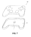
- FIG. 7 is a view illustrating a gaming device including the linear vibration actuator.
- a compact linear vibration actuator 1 is built into a communication device such as a mobile communication device (e.g. a cell phone), is used as a vibration generator for the calling function, and has a coin form with a diameter of approximately 10 mm and a thickness of approximately 3 mm.
- a mobile communication device e.g. a cell phone
- a casing 2 of the linear actuator 1 is formed from a cup-like upper casing part 11 formed from a non-magnetic material (such as stainless steel) and a lower casing part 12 with a disc-like shape in a non-magnetic material (such as stainless steel) for closing the open side of the upper casing part 11 .
- the lower casing part 12 is fitted inside the circular-form open end of the upper casing part 11 , and the open end of the upper casing part 11 is then bent inwards.
- the upper casing part 11 may be welded to the lower casing part 12 .
- the casing 2 houses a ring-like magnet 13 magnetized along an axial line L direction of the shaft 20 to give an N pole and a S pole.
- Yokes 14 and 16 formed from thin ring-like magnetic bodies are fixed using an adhesive agent to flat surface parts 13 a and 13 b of the magnet 13 so as to oppose each other vertically across the magnet 13 .
- cross-like adhesive agent filling holes 14 a and 16 a are formed at four locations in a circumferential direction thereof. As a result, the adhesive effect of the adhesive agent can be increased.
- the weight 15 is made, for example, from tungsten, and a needle is formed by the magnet 13 , yokes 14 and 16 and weight 15 .
- a thin plate spring 17 is fixed by welding to the lower side flat surface part 15 a of the weight 15 .
- the plate spring 17 is formed by a ring-like upper side seat part 17 a with a small diameter, a lower side seat part 17 b with a large diameter, and an arc-like elastic section 17 c linking the upper side seat part 17 a and the lower side seat part 17 b . Then, the upper side seat part 17 a is welded to the lower side flat surface part 15 a of the weight 15 and the lower side seat part 17 b is welded to the inner wall surface of the lower casing part 12 .
- the lower casing part 12 includes a circular disc-like main body part 12 a of a form that matches the open end of the upper casing part 11 and a tongue piece 12 d that protrudes in a radial direction from the main body part 12 a .
- a flexible circuit board 19 is fixed to the inner wall surface of the lower casing part 12 .
- the flexible circuit board 19 includes a ring-like main body part 19 a mounted on the inner wall surface of the lower casing part 12 and an extending part 19 b mounted on a tongue piece 12 d of the lower casing part 12 .
- an opening part 19 d for passing through a bobbin 21 and a shaft 20 is formed in the main body part 19 a , an electrical supply terminal 19 c is provided in the extending part 19 b , and the electrical terminal 19 c is exposed to the outside.
- a press fitting hole 12 c for providing the shaft 20 in a standing arrangement is provided.
- the shaft 20 is formed from a magnetic body and supports the bobbin 21 , which is made of resin.
- the bobbin 21 includes a center hole 21 a for insertion of the shaft 20 , flange parts 21 b and 21 c positioned at the two ends in an axial line L direction, and a flange-like segment part 21 d positioned between the flange parts 21 b and 21 c .
- a first bobbin part 21 A is configured by the flange part 21 b , the segment part 21 d and a support 21 e
- a second bobbin part 21 B is configured by the flange part 21 c , the segment part 21 d and a support 21 f
- the first bobbin part 21 A and the second bobbin part 21 B are arranged to be parallel with the axial line L direction.
- the shaft 20 is press fitted or inserted with extremely low error into the center hole 21 a that pierces the support 21 e and the support 21 f.
- a coil 24 is formed from a first coil part 22 configured by winding coil wire on the support 21 e of the first bobbin part 21 A, and a second coil part 23 configured by winding coil wire on the support 21 f of the second bobbin part 21 B in the opposite direction to the first coil part 22 .
- the first coil part 22 and the second coil part 23 are arranged to be parallel with the axial line L direction. Further the coil wire of the first coil part 22 and the coil wire of the second coil part 23 are connected in series, and the coil 24 is connected to the flexible circuit board 19 .
- the ring-like magnet 13 is arranged to surround the coil 24 supported by the shaft 20 , with the axial line L at the center thereof, and supported within the casing 2 by a plate spring 17 .
- the plate spring 17 is a compression spring, biasing the magnet 13 and a weight 15 in the axial line L direction of the shaft 20 .
- the magnet 13 is arranged to straddle the first coil part 22 and the second coil part 23 so that the inner circumferential surface 13 d of the magnet 13 and the segment part 21 d of the bobbin 21 oppose each other.
- a magnetic circuit is formed by the magnet 13 and the shaft 20 , and the coil 24 wound on the bobbin 21 is supported by the shaft 20 that forms one part of the magnetic circuit, and is wound around and centered on the shaft 20 .
- the shaft 20 can be effectively used to determine the position of the coil 24 .
- the coil 24 position can be determined based on the shaft 20 standing within the casing 2 , making it possible to easily improve the positioning accuracy of the coil 24 within the casing 2 and making it easier to fit the bobbin 21 in the linear actuator 1 .
- a gap P 1 between an outer circumferential surface 15 c of the weight 15 surface and a circumferential wall 11 b of the upper casing part 11 of the casing 2 is narrower than a gap P 2 between the inner circumferential surface 13 d of the magnet 13 and the outer circumferential surface 24 a of the coil 24 .
- the outer circumferential surface 24 a of the coil 24 and the inner circumferential surface 13 d of the magnet 13 will not collide even if a collision occurs between the outer circumferential surface 15 c of the weight 15 and the circumferential wall 11 b of the casing 2 during a dropping impact. Hence, it becomes less likely that wires will break in coil 24 under a dropping impact.
- the flange-like segment part 21 d of the bobbin 21 protrudes from the outer circumferential surfaces 22 a and 23 a of the first coil part 22 and the second coil part 23 .
- This construction enables the effective use of the segment part 21 d to divide the first coil part 22 and the second coil part 23 .
- the free end of the segment part 21 d will collide with the inner circumferential surface 13 d of the magnet 13 .
- the segment part 21 d makes it easier to wind coil wire in different winding directions on the bobbin 21 .
- the weight 15 has formed therein concave parts 15 e for mass adjustment of the weight 15 , in an upper side flat surface part 15 d perpendicular to the axial line L.
- a filling liquid such as a mixture of tungsten powder and adhesive agent
- the weight 15 vibrates along the axial line L direction via the plate spring 17 .
- a voltage of a predetermined frequency such as 5 V, 200 Hz
- the weight 15 may not vibrate within the casing 2 or may not provide the desired vibration.
- the concave parts 15 e for mass adjustment is formed at equal intervals in the upper side flat surface part 15 d of the weight 15 .
- the mass of the weight 15 can be increased to facilitate smooth vibration of the weight 15 at the frequency inputted to the coil 24 . Note that the correction measure in this case is not applicable to a case in which the weight 15 is too heavy and fails to vibrate.
- the linear actuator 1 is inspected in a state with the upper casing part 11 removed, and linear actuators 1 that do not vibrate appropriately are corrected in the manner described above.
- the two ends of the shaft 20 are press-fitted into the press fitting hole 11 c of the upper casing part 11 and the press fitting hole 12 c of the lower casing part 12 respectively, and the shaft 20 is thereby provided standing in the center of the casing 2 .
- hemispherical convex parts 26 are provided at equally spaced intervals in the circumferential direction.
- the convex parts 26 which are made from resin, allow the bobbin 21 to be securely fitted between the upper casing part 11 and the lower casing part 12 as result of contact with the inner wall surface of the upper casing part 11 during assembly. As a result of this arrangement, play in the bobbin 21 is suppressed and the anti-noise properties and resistance to dropping impacts can be improved.
- the linear vibration actuator 100 according to the 2nd embodiment illustrated in FIG. 4 differs from the linear vibration actuator 1 of the 1st embodiment in that the yokes 14 and 16 used in the 1st embodiment are not fixed to the pair of opposing ring-like flat surface parts 13 a and 13 b of the magnet 13 .
- Note that other elements of the linear vibration actuator 100 of the 2nd embodiment are identical to those of the linear vibration actuator 1 of the 1st embodiment, and so the same symbols are allocated to these elements in FIG. 4 and descriptions of them are omitted.
- the effect of the distance R between a bottom end 22 b of the first coil part 22 and the flat surface part 13 b of the bottom side of the magnet 13 is important.
- This effect is useful for increasing the efficiency of vibration using the weight 15 .
- the same effect applies to the lowermost end of the magnet 13 .
- the linear vibration actuator 1 can be mounted within a casing of a smartphone 110 to form a mobile communication device having a vibration notification function.
- a circuit board 111 of the smartphone 110 By electrically connecting a circuit board 111 of the smartphone 110 with the electrical supply terminal 19 c of the flexible circuit board 19 of the linear vibration actuator 1 , it is possible to use the linear vibration actuator 1 as a vibration generator.
- vibrations may be generated when an incoming call reaches the mobile communication device, or an operation is performed on the mobile communication device.
- the linear vibration actuator 1 can be mounted within a casing of a controller 120 of a game machine to form a gaming device having a vibration notification function.
- a circuit board 121 of the controller 120 By electrically connecting a circuit board 121 of the controller 120 with the electrical supply terminal 19 c of the flexible circuit board 19 of the linear vibration actuator 1 , it is possible to use the linear vibration actuator 1 as a vibration generator.
- the gaming device may be a mobile gaming machine, a steering wheel or the like of a personal computer or the like. In this case, vibrations are generated according to the situation in the game to enhance a sense of reality for the user.
Landscapes
- Engineering & Computer Science (AREA)
- Power Engineering (AREA)
- Apparatuses For Generation Of Mechanical Vibrations (AREA)
- Reciprocating, Oscillating Or Vibrating Motors (AREA)
Applications Claiming Priority (4)
| Application Number | Priority Date | Filing Date | Title |
|---|---|---|---|
| JP2013-028705 | 2013-02-18 | ||
| JP2013028705 | 2013-02-18 | ||
| JP2013-194516 | 2013-09-19 | ||
| JP2013194516A JP5889259B2 (ja) | 2013-02-18 | 2013-09-19 | リニア型振動アクチュエータ |
Publications (2)
| Publication Number | Publication Date |
|---|---|
| US20140232211A1 US20140232211A1 (en) | 2014-08-21 |
| US9621015B2 true US9621015B2 (en) | 2017-04-11 |
Family
ID=51311226
Family Applications (1)
| Application Number | Title | Priority Date | Filing Date |
|---|---|---|---|
| US14/180,575 Expired - Fee Related US9621015B2 (en) | 2013-02-18 | 2014-02-14 | Linear vibration actuator and mobile communication device or gaming device including the same |
Country Status (5)
| Country | Link |
|---|---|
| US (1) | US9621015B2 (ja) |
| JP (1) | JP5889259B2 (ja) |
| KR (1) | KR20140104353A (ja) |
| CN (1) | CN103997181A (ja) |
| TW (1) | TWI610519B (ja) |
Cited By (3)
| Publication number | Priority date | Publication date | Assignee | Title |
|---|---|---|---|---|
| US20180019651A1 (en) * | 2016-07-15 | 2018-01-18 | Mplus Co., Ltd. | Linear vibration generator |
| US10559994B2 (en) * | 2016-07-15 | 2020-02-11 | Mplus Co., Ltd. | Linear vibration motor |
| US20230143064A1 (en) * | 2021-11-05 | 2023-05-11 | Ming-Hung Lin | Vibration unit, speaker and manufacturing method of the vibration unit |
Families Citing this family (33)
| Publication number | Priority date | Publication date | Assignee | Title |
|---|---|---|---|---|
| JP2013233537A (ja) * | 2012-04-10 | 2013-11-21 | Hosiden Corp | バイブレータ |
| JP6029854B2 (ja) * | 2012-05-22 | 2016-11-24 | ミネベア株式会社 | 振動子及び振動発生器 |
| JP6309871B2 (ja) * | 2014-09-30 | 2018-04-11 | 日本電産セイミツ株式会社 | 振動モータ |
| WO2016194762A1 (ja) * | 2015-05-29 | 2016-12-08 | 日本電産コパル株式会社 | リニア振動モータ |
| JP6517591B2 (ja) * | 2015-06-01 | 2019-05-22 | 日本電産サンキョー株式会社 | リニアアクチュエータの製造方法およびリニアアクチュエータ |
| KR20170005686A (ko) * | 2015-07-06 | 2017-01-16 | 자화전자(주) | 선형 진동 발생 장치 |
| CN205377621U (zh) * | 2015-11-03 | 2016-07-06 | 瑞声光电科技(常州)有限公司 | 振动电机 |
| CN105720776B (zh) * | 2016-03-28 | 2019-04-12 | 歌尔股份有限公司 | 振动马达以及便携式设备 |
| JP6692242B2 (ja) * | 2016-07-25 | 2020-05-13 | 日本電産コパル株式会社 | 振動モータ |
| US10252155B2 (en) * | 2016-08-22 | 2019-04-09 | Sony Interactive Entertainment Inc. | Brushless two dimensional haptic actuator |
| CN106329871A (zh) * | 2016-09-30 | 2017-01-11 | 歌尔股份有限公司 | 线性振动马达以及电子设备 |
| CN106357080A (zh) * | 2016-09-30 | 2017-01-25 | 歌尔股份有限公司 | 线性振动马达 |
| KR20180059973A (ko) * | 2016-11-28 | 2018-06-07 | (주)파트론 | 선형진동자 |
| CN106849587B (zh) * | 2017-03-14 | 2022-04-05 | 歌尔股份有限公司 | 线性振动马达及电子设备 |
| CN107276361A (zh) * | 2017-08-11 | 2017-10-20 | 歌尔股份有限公司 | 一种线性振动马达 |
| CN107317454A (zh) * | 2017-08-11 | 2017-11-03 | 歌尔股份有限公司 | 线性振动马达 |
| CN207069866U (zh) * | 2017-08-11 | 2018-03-02 | 歌尔科技有限公司 | 线性振动马达 |
| CN107257190B (zh) * | 2017-08-11 | 2020-06-02 | 歌尔股份有限公司 | 线性振动马达 |
| CN207069865U (zh) * | 2017-08-11 | 2018-03-02 | 歌尔科技有限公司 | 线性振动马达 |
| CN109428456A (zh) * | 2017-08-21 | 2019-03-05 | 日本电产三协电子(东莞)有限公司 | 致动器 |
| KR102026901B1 (ko) * | 2017-08-25 | 2019-11-04 | 주식회사 엠플러스 | 코일의 단선 방지 구조를 포함하는 선형 진동발생장치. |
| IT201800003406A1 (it) * | 2018-03-09 | 2019-09-09 | Powersoft S P A | Sistema di controllo della vibrazione di una piattaforma |
| JP7157305B2 (ja) * | 2018-03-26 | 2022-10-20 | ミツミ電機株式会社 | 振動アクチュエータ及び電子機器 |
| CN208675084U (zh) * | 2018-08-03 | 2019-03-29 | 瑞声科技(南京)有限公司 | 线性振动电机 |
| CN208589896U (zh) * | 2018-08-03 | 2019-03-08 | 瑞声科技(南京)有限公司 | 线性振动电机 |
| CN208589899U (zh) * | 2018-08-03 | 2019-03-08 | 瑞声科技(南京)有限公司 | 线性振动电机 |
| EP3846326A4 (en) * | 2018-08-28 | 2022-05-04 | Minebea Mitsumi Inc. | VIBRATION ACTUATOR AND ELECTRONIC EQUIPMENT |
| JP7222661B2 (ja) * | 2018-10-31 | 2023-02-15 | ミネベアミツミ株式会社 | 振動アクチュエータ及び振動呈示装置 |
| CN109617355B (zh) * | 2018-12-27 | 2021-02-23 | 瑞声科技(南京)有限公司 | 线性振动电机 |
| US12081066B2 (en) * | 2019-03-14 | 2024-09-03 | Foster Electric Company, Limited | Actuator and display unit provided therewith |
| CN110429785A (zh) * | 2019-08-28 | 2019-11-08 | 领先科技(东台)有限公司 | 一种线圈内嵌套法兰磁轭的线性马达 |
| JP7393285B2 (ja) * | 2020-04-02 | 2023-12-06 | ニデックインスツルメンツ株式会社 | アクチュエータ |
| CN215772886U (zh) * | 2020-07-10 | 2022-02-08 | 日本电产株式会社 | 振动马达及触觉器件 |
Citations (9)
| Publication number | Priority date | Publication date | Assignee | Title |
|---|---|---|---|---|
| US6249198B1 (en) * | 1998-06-16 | 2001-06-19 | Huntleigh Technology Plc | Magnetic actuator |
| US20100066182A1 (en) * | 2008-09-16 | 2010-03-18 | Sanyo Seimitsu Co., Ltd. | Reciprocating vibrator |
| US20100102646A1 (en) * | 2008-10-28 | 2010-04-29 | Sanyo Electric Co., Ltd. | Reciprocating vibration generator |
| US20110018366A1 (en) | 2009-07-27 | 2011-01-27 | Jun Kun Choi | Linear vibrator |
| US20110068639A1 (en) * | 2009-09-24 | 2011-03-24 | Samsung Electro-Mechanics Co., Ltd. | Horizontal linear vibrator |
| US20110198949A1 (en) * | 2010-02-16 | 2011-08-18 | Sanyo Electric Co., Ltd. | Vibration generator |
| US20120146557A1 (en) * | 2010-12-09 | 2012-06-14 | Korea Advanced Institute Of Science And Technology | Vibration generating module, actuator using the same, handheld device, method for generating vibration and recording medium thereof |
| US20120319506A1 (en) * | 2011-06-16 | 2012-12-20 | Jahwa Electronics Co., Ltd | Linear vibration generating apparatus |
| US20130342034A1 (en) * | 2012-06-26 | 2013-12-26 | Samsung Electro-Mechanics Co., Ltd. | Linear vibrator |
Family Cites Families (5)
| Publication number | Priority date | Publication date | Assignee | Title |
|---|---|---|---|---|
| TW501329B (en) * | 2001-01-31 | 2002-09-01 | Sunonwealth Electr Mach Ind Co | DC brushless vibrating motor |
| JP2003174759A (ja) * | 2001-05-08 | 2003-06-20 | Staf Corp | 磁気駆動装置 |
| JP2009166016A (ja) * | 2008-01-21 | 2009-07-30 | Sanyo Electric Co Ltd | 往復振動発生器 |
| JP5537984B2 (ja) * | 2010-02-16 | 2014-07-02 | 日本電産セイミツ株式会社 | 往復振動発生器 |
| KR101055508B1 (ko) * | 2010-12-31 | 2011-08-08 | 삼성전기주식회사 | 선형 진동모터 |
-
2013
- 2013-09-19 JP JP2013194516A patent/JP5889259B2/ja not_active Expired - Fee Related
-
2014
- 2014-02-13 CN CN201410050370.6A patent/CN103997181A/zh active Pending
- 2014-02-14 TW TW103104895A patent/TWI610519B/zh not_active IP Right Cessation
- 2014-02-14 US US14/180,575 patent/US9621015B2/en not_active Expired - Fee Related
- 2014-02-14 KR KR1020140017261A patent/KR20140104353A/ko not_active Application Discontinuation
Patent Citations (10)
| Publication number | Priority date | Publication date | Assignee | Title |
|---|---|---|---|---|
| US6249198B1 (en) * | 1998-06-16 | 2001-06-19 | Huntleigh Technology Plc | Magnetic actuator |
| US20100066182A1 (en) * | 2008-09-16 | 2010-03-18 | Sanyo Seimitsu Co., Ltd. | Reciprocating vibrator |
| US20100102646A1 (en) * | 2008-10-28 | 2010-04-29 | Sanyo Electric Co., Ltd. | Reciprocating vibration generator |
| US20110018366A1 (en) | 2009-07-27 | 2011-01-27 | Jun Kun Choi | Linear vibrator |
| JP2011030403A (ja) | 2009-07-27 | 2011-02-10 | Samsung Electro-Mechanics Co Ltd | 線形振動子 |
| US20110068639A1 (en) * | 2009-09-24 | 2011-03-24 | Samsung Electro-Mechanics Co., Ltd. | Horizontal linear vibrator |
| US20110198949A1 (en) * | 2010-02-16 | 2011-08-18 | Sanyo Electric Co., Ltd. | Vibration generator |
| US20120146557A1 (en) * | 2010-12-09 | 2012-06-14 | Korea Advanced Institute Of Science And Technology | Vibration generating module, actuator using the same, handheld device, method for generating vibration and recording medium thereof |
| US20120319506A1 (en) * | 2011-06-16 | 2012-12-20 | Jahwa Electronics Co., Ltd | Linear vibration generating apparatus |
| US20130342034A1 (en) * | 2012-06-26 | 2013-12-26 | Samsung Electro-Mechanics Co., Ltd. | Linear vibrator |
Cited By (4)
| Publication number | Priority date | Publication date | Assignee | Title |
|---|---|---|---|---|
| US20180019651A1 (en) * | 2016-07-15 | 2018-01-18 | Mplus Co., Ltd. | Linear vibration generator |
| US10559994B2 (en) * | 2016-07-15 | 2020-02-11 | Mplus Co., Ltd. | Linear vibration motor |
| US10622877B2 (en) * | 2016-07-15 | 2020-04-14 | Mplus Co., Ltd. | Linear vibration generator |
| US20230143064A1 (en) * | 2021-11-05 | 2023-05-11 | Ming-Hung Lin | Vibration unit, speaker and manufacturing method of the vibration unit |
Also Published As
| Publication number | Publication date |
|---|---|
| US20140232211A1 (en) | 2014-08-21 |
| KR20140104353A (ko) | 2014-08-28 |
| JP2014176841A (ja) | 2014-09-25 |
| TWI610519B (zh) | 2018-01-01 |
| CN103997181A (zh) | 2014-08-20 |
| TW201434245A (zh) | 2014-09-01 |
| JP5889259B2 (ja) | 2016-03-22 |
Similar Documents
| Publication | Publication Date | Title |
|---|---|---|
| US9621015B2 (en) | Linear vibration actuator and mobile communication device or gaming device including the same | |
| US9467035B2 (en) | Vibration actuator | |
| US20170104401A1 (en) | Vibrator unit and vibration generator | |
| JP7234256B2 (ja) | 機械的振動エネルギーを電気エネルギーに変換するための電気機械発電機 | |
| US10170965B2 (en) | Linear vibration motor | |
| JP2012016153A (ja) | 振動アクチュエータ | |
| US20130272550A1 (en) | Vibration generator | |
| KR101228297B1 (ko) | 선형 진동 발생장치 | |
| US11394285B2 (en) | Vibration actuator and electronic device | |
| KR20100111368A (ko) | 진동 장치 | |
| CN103357566A (zh) | 振动器 | |
| US20170126109A1 (en) | Vibration motor | |
| JP6262189B2 (ja) | リニア型振動アクチュエータ | |
| KR101914530B1 (ko) | 진동 발생 장치 | |
| KR20170035464A (ko) | 선형 진동자 | |
| WO2017073855A1 (ko) | 진동 액추에이터 | |
| WO2006109609A1 (ja) | 加速度センサおよび加速度センサ装置 | |
| KR102283551B1 (ko) | 탄성부재, 이를 구비한 선형 진동발생장치 | |
| KR102037777B1 (ko) | 진동 모터 | |
| KR101113701B1 (ko) | 선형 진동 발생장치 | |
| KR102066662B1 (ko) | 진동 모터 | |
| WO2023234293A1 (ja) | 振動アクチュエータ及び電子機器 | |
| KR20180127857A (ko) | 진동모터 | |
| US20240009701A1 (en) | Oscillatory actuator | |
| KR102306513B1 (ko) | 와이드 밴드 선형 진동 모터 |
Legal Events
| Date | Code | Title | Description |
|---|---|---|---|
| AS | Assignment |
Owner name: NIDEC COPAL CORPORATION, JAPAN Free format text: ASSIGNMENT OF ASSIGNORS INTEREST;ASSIGNORS:KATADA, YOSHINORI;SONOKI, HIROHIKO;HIGASHI, DAISUKE;AND OTHERS;SIGNING DATES FROM 20140120 TO 20140129;REEL/FRAME:032220/0842 |
|
| STCF | Information on status: patent grant |
Free format text: PATENTED CASE |
|
| FEPP | Fee payment procedure |
Free format text: MAINTENANCE FEE REMINDER MAILED (ORIGINAL EVENT CODE: REM.); ENTITY STATUS OF PATENT OWNER: LARGE ENTITY |
|
| LAPS | Lapse for failure to pay maintenance fees |
Free format text: PATENT EXPIRED FOR FAILURE TO PAY MAINTENANCE FEES (ORIGINAL EVENT CODE: EXP.); ENTITY STATUS OF PATENT OWNER: LARGE ENTITY |
|
| STCH | Information on status: patent discontinuation |
Free format text: PATENT EXPIRED DUE TO NONPAYMENT OF MAINTENANCE FEES UNDER 37 CFR 1.362 |
|
| FP | Lapsed due to failure to pay maintenance fee |
Effective date: 20210411 |