US9530106B2 - System and method for digital multi-lateral proofreading during a meeting - Google Patents
System and method for digital multi-lateral proofreading during a meeting Download PDFInfo
- Publication number
- US9530106B2 US9530106B2 US12/521,721 US52172107A US9530106B2 US 9530106 B2 US9530106 B2 US 9530106B2 US 52172107 A US52172107 A US 52172107A US 9530106 B2 US9530106 B2 US 9530106B2
- Authority
- US
- United States
- Prior art keywords
- screen
- author
- data
- usb
- computer
- Prior art date
- Legal status (The legal status is an assumption and is not a legal conclusion. Google has not performed a legal analysis and makes no representation as to the accuracy of the status listed.)
- Active, expires
Links
Images


Classifications
-
- G—PHYSICS
- G06—COMPUTING; CALCULATING OR COUNTING
- G06Q—INFORMATION AND COMMUNICATION TECHNOLOGY [ICT] SPECIALLY ADAPTED FOR ADMINISTRATIVE, COMMERCIAL, FINANCIAL, MANAGERIAL OR SUPERVISORY PURPOSES; SYSTEMS OR METHODS SPECIALLY ADAPTED FOR ADMINISTRATIVE, COMMERCIAL, FINANCIAL, MANAGERIAL OR SUPERVISORY PURPOSES, NOT OTHERWISE PROVIDED FOR
- G06Q10/00—Administration; Management
Definitions
- the present invention relates to the field of display systems. More particularly, the invention relates to a system and method for digital multi-lateral proofreading during a meeting.
- the present device provides a novel system and method for the digital proofreading of contracts during the course of a front-to-front meeting by the use of a dual screen computer monitor, to more efficiently utilize meeting time.
- U.S. Pat. No. 5,796,577 and U.S. Pat. No. 5,856,819 disclose a bi-directional presentation device having a pair of screens facing in generally opposite directions, for displaying an image visible to an audience on both sides of the display device.
- US 2002/0109662 discloses a dual screen computer display consisting of two display panels which may face in opposite directions or in the same direction to provide an enlarged viewing area.
- 6,295,038 and US 2004/0051679 disclose a laptop computer having a first display screen that can be observed by an operator and a second display screen hingedly secured to the first screen, by which an observer of a presentation can see the same information viewed by the operator.
- An image is usually generated by the operator so that it may be viewed by a person participating in a front-to-front meeting.
- the applicant is unaware of any prior art references that describes the ability of two participants of a meeting to interact with a display, particularly a textual display, without having to add any hardware to the personal computer in use.
- a “computer monitor unit” is a set of monitors disposed on a common surface, e.g. a desk of a co-author, on each of which can be displayed computer generated images.
- the images that are displayed on each screen of the same computer monitor unit are generally identical.
- a computer monitor unit may include screens, e.g. two or three, that are in communication with corresponding video ports of the same computer.
- the type of multi-screened computer monitor units that is used in conjunction with the present invention is one that has oppositely facing screens and an input device for each corresponding screen.
- the term “oppositely facing screens” means two screens disposed at a relative angular spacing ranging from approximately 60-180 degrees. Since co-authors are provided with corresponding input devices and can simultaneously view images displayed on oppositely facing screens of a multi-screened computer unit, a co-author can correct the composition while discussing the content of the composition with a fellow co-author. A discussion between co-authors concerning the content of a composition will be called a “meeting”.
- Two screens of the monitor unit will be referred herein as the “first side” and the “second side”, respectively, or alternatively, as the “agent screen” or the “client screen”, respectively.
- a co-author located at the first side will be called a “primary co-author”, and a co-author located at a second side will be called a “secondary co-author”.
- the monitor unit has three screens, there may be two second sides.
- a “composition” is a text or a collection of other visible information which is displayable on a screen of a computer monitor unit, e.g. a literary work, an agreement such as a contract, a transcript of a court proceeding, a drawing, a game, a seating arrangement within an airplane which is displayed to a passenger at a check-in counter, a bank statement, and a sale slip.
- a composition is displayed on said screen, an action for revealing and correcting mistakes in the composition, such as misprints, inaccurate statements, or deleted statements, will be called “digital proofreading”.
- the composition is proofread by more than one co-author as each co-author views the composition on a corresponding screen of the monitor unit during the course of a meeting, the action will be called “multi-lateral proofreading”.
- a “co-author” is one who is involved with multi-lateral proofreading, and is not necessarily the one who originally drafted, or was involved in the drafting of, the composition.
- the composition is an agreement such as a contract or a sale slip by which the seller agreed to sell a product
- the primary co-author will be called the “grantor” and the secondary co-author will be called the “grantee”.
- the grantor has priority in terms of correcting the composition, and can prevent the grantee from correcting the composition, if so desired.
- a digital multi-lateral proofreading system during a meeting comprises:
- the multi-screened monitor unit is a kit which is releasably coupleable with a computer.
- a multi-lateral proofreading operation may therefore be performed without having to change the hardware of the computer.
- system further comprises means for preventing an agent input device and a client input device to operate simultaneously during a multi-lateral proofreading operation.
- the monitor unit comprises a controller which is in data communication with the computer, for converting signals generated by an input device into USB signals.
- the multi-screened monitor unit comprises means for receiving VGA data from the computer and for transmitting the same to the first screen, and means for receiving USB video data and for transmitting the same to each of the second screens, images associated with said transmitted VGA data and with said transmitted USB video data being simultaneously displayable on said first and second screens, respectively.
- the multi-screened monitor unit further comprises a control module for controlling the flow of USB control and video data received from the computer, a switch module for delivering video data to a client side in response to the operation of the control module, a video splitter for splitting received VGA data into a first portion transmitted through a first line to the first screen and into a second portion transmitted through a second line to said switch module, a first USB segment extending from said control module to said switch module, and a second USB segment extending from said switch module to the second screen.
- a control module for controlling the flow of USB control and video data received from the computer
- a switch module for delivering video data to a client side in response to the operation of the control module
- a video splitter for splitting received VGA data into a first portion transmitted through a first line to the first screen and into a second portion transmitted through a second line to said switch module, a first USB segment extending from said control module to said switch module, and a second USB segment extending from said switch module to the second screen.
- system further comprises means for identifying each of the co-authors.
- system further comprises an authentication server with which the computer is in data communication, for authenticating a co-author identification.
- system further comprises means for disabling a proofreading operation if a co-author identification is not authenticated.
- system further comprises means for attaching a digital signature to an approved composition.
- a primary or secondary co-author input device is an input device which is external to the monitor unit, such as a keyboard, a mouse, and an electronic pen.
- a primary or secondary co-author input device is an input device which is integral with the monitor unit, such as a touch screen, a credit card reader, or a biometric reader.
- a secondary co-author input device is coupled to the monitor unit.
- a secondary co-author input device is coupled to the computer.
- a secondary co-author input device is in wireless communication with the computer.
- the transmitted corrected image data is a displayed feature of the composition which is indicated by means of a touch screen.
- the computer is in communication with a data network.
- the present invention is also directed to a method for the digital multi-lateral proofreading of a composition during a meeting, comprising:
- all client input devices are disabled for a predetermined period of time after an agent has performed a proofreading operation, and all agent input devices are disabled for a predetermined period of time after a client has performed a proofreading operation.
- a primary co-author sets a secondary co-author input device to a disabled mode.
- the monitor unit operates in an agent only mode, a uniform mode whereby the agent side screen and client side screen both display the same images, or in a dual mode, whereby in the dual mode the agent side screen displays images corresponding to received video graphics array (VGA) data and the client side screen displays images corresponding to received universal serial bus (USB) data.
- VGA video graphics array
- USB universal serial bus
- the present invention is also directed to a multi-screened computer monitor unit capable of being coupled to a computer, comprising:
- the first screen is stationary and the second screen is displaceable.
- the second screen is angularly spaced from the first screen.
- the multi-screened monitor unit further comprises means for selecting a desired mode of operation, corresponding USB control data being transmittable to the control module upon selection, of the desired mode of operation.
- the control module generates a disable signal and transmits the same to the switch module during an agent only mode to suppress the transmission of the VGA data via the second line.
- the control module generates an enable signal and transmits the same to the switch module during a uniform mode to enable the transmission of the VGA data via the first and second lines simultaneously.
- the control module generates a disable signal and transmits the same to the switch module during a dual mode, the USB video data being transmittable via the first and second USB bus segments to the client side.
- FIG. 1 is a perspective view of one embodiment of a computer monitor unit comprising two oppositely facing screens mounted in a common housing and in communication with a common computer;
- FIG. 2 is a perspective view of another embodiment of a computer monitor unit which comprises three screens mounted in a common triangularly shaped housing and in communication with a common computer;
- FIG. 3 is a block diagram of a digital multi-lateral proofreading system, according to one embodiment of the invention.
- FIG. 5 is a schematic diagram of a digital multi-lateral proofreading system, illustrating exemplary input devices
- FIG. 6 is a perspective view of another embodiment of a computer monitor unit comprising two oppositely facing screens
- FIG. 7 is a perspective view of another embodiment of a computer monitor unit comprising a first stationary screen and a second displaceable screen;
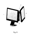
- FIG. 8 is a perspective view of another embodiment of a computer monitor unit comprising two stationary screens that are separated by a fixed angular distance;
- FIG. 9 is a perspective view of another embodiment of a computer monitor unit comprising a first stationary screen and a second axially slidable screen;
- FIG. 10 is a block diagram of a digital multi-lateral proofreading system according to another embodiment of the invention.
- the present invention is a novel system and method for the digital review and correction (hereinafter referred to as “proofreading”) of a composition displayed on each screen of a multi-screened computer monitor unit during the course of a meeting between co-authors of the composition.
- a meeting may be a front-to-front discussion or conferral between an agent of an establishment, such as a salesman or a bank clerk, and a client or potential client of that establishment, or between a grantor and grantee of an agreement.
- a meeting may also be conducted among many participants; however, only those participants who have privileges to correct the composition by means of a dedicated user interface, as will be described hereinafter, will be called a “co-author”.
- Each co-author views, and interfaces with, a corresponding screen of a monitor unit, such as a dual screened monitor unit, by which oppositely facing screens may present a composition of graphical or other visible information simultaneously to each of the co-authors.
- the composition is generally relevant to the nature of the meeting.
- a secondary co-author on a second side of the monitor unit is able to view images of the composition without having to lean, while sitting, in an awkward position over the table supporting the monitor unit in order to view the first side thereof.
- the secondary co-author is also able to proofread the composition without having to wait for the primary co-author to print the composition, distribute the printed pages to the other co-authors, and request the primary co-author to correct the composition.
- FIG. 1 illustrates one embodiment of a multi-screened computer monitor unit, which is generally designated by numeral 4 .
- Monitor unit 4 comprises two screens 3 a and 3 b which face in opposite directions, i.e. an angular spacing of 180 degrees, and two input devices 2 a and 2 b , respectively, e.g. keyboards as shown.
- Monitor unit 4 is essentially a unique interactive device, as will be described hereinafter, and is adapted to be coupled to computer 6 and therefore may be sold as a kit.
- the first side screens 3 a and the second side screen 3 b are mounted in a common housing 1 , which is schematically shown in exploded fashion. Each screen may be of any desired configuration, such as a CRT or LCD.
- Computer 6 generates two identical sets of images which are displayed simultaneously on screens 3 a and 3 b , respectively, by means of cables 2 a and 2 b , respectively, or by any other suitable data transmission medium.
- a single input device 5 a is coupled to computer 6 by cable 7 , and a co-author viewing the images displayed on screen 3 a is therefore able to proofread the displayed images by means of input device 5 a .
- Input device 5 b is coupled directly to screen 3 b by cable 8 , and a co-author viewing the images displayed on screen 3 b is therefore able to proofread the displayed images by means of input device 5 b and the system which will be described hereinafter.
- a multi-screened computer monitor unit 134 illustrated in FIG. 6 may comprise two screens 130 and 139 which face in opposite directions and which are mounted obliquely with respect to top surface 136 of the monitor unit.
- FIG. 7 illustrates a monitor unit 44 which comprises a first stationary screen 41 and a second displaceable screen 42 .
- Stationary screen 41 is supported by an underlying stand 43 , which may be V-shaped as shown or configured in any other desired shape.
- a connecting element 47 extends from first stationary screen 41 to second displaceable screen 42 , and is provided with a vertical pivot 49 .
- the pivotal screen 42 which may oriented at an angular distance of approximately 90 degrees, as illustrated, or any other convenient angular distance, from stationary screen 41 , the participant may confer with the agent in a front-to-front meeting without interference from screen 42 .
- the participant may advantageously rotate second screen 42 about pivot 49 until the images displayed thereon are visible to the participant.
- a flexible cable (not shown) through which data is transmitted to screen 42 may be contained within connecting element 47 .
- monitor unit 54 comprises a fixed connecting element 58 between screens 41 and 42 .
- a client may sit at an angle of approximately 90 degrees from the agent and view a display of images while conferring with, or while waiting to confer with, the agent.
- FIG. 3 illustrates a block diagram of a digital multi-lateral proofreading system, which is designated by numeral 20 , according to one embodiment of the invention.
- Proofreading system 20 comprises multi-screen computer monitor unit 28 in which is housed monitor controller 22 , and screens 24 and 25 .
- Controller 22 is in data communication with computer 26 via Universal Serial Bus (USB) cable 23 .
- External input device 27 i.e. spaced from the monitor housing, is coupled with computer 26 by cable 7 and is used by the primary co-author to proofread the composition displayed on screen 24 , as is well known to those skilled in the art.
- Input device 29 is coupled with controller 22 by cable 8 and is used by the secondary co-author to proofread the composition displayed on screen 25 .
- system 20 is suitable for the interaction therewith of two secondary co-authors, and that each co-author may use more than one external input device provided with a corresponding cable, such as a keyboard and a mouse, in order to proofread a composition.
- Controller 22 is adapted to convert the signals generated by each interface device used by a secondary co-author into USB signals. In order to synchronize the generation and transmission of the USB signals from each input device, controller 22 is generally multi-channeled and is provided with a processor.
- FIG. 4 illustrates a block diagram of a digital multi-lateral proofreading system 40 which comprises multi-screen computer monitor unit 45 in which is housed monitor controller 22 , and screens 24 and 25 .
- the connectivity and operation of computer 26 with respect to monitor unit 45 are similar to the description of FIG. 3 , and therefore need not be repeated for brevity.
- the grantor and grantee interact with monitor unit 45 during a proofreading operation by means of external input devices 27 and 29 , respectively, and by one or more integral input devices 48 .
- An integral input device is one that cannot be detached from the housing of monitor unit 45 .
- An example of an integral input device is a touch screen, which is of great utility to co-authors during a meeting.
- the desired feature is pressed on the first side and indicated by a distinctive color or other indication means, and said feature is similarly indicated simultaneously on the second side. If so desired, the touch screen may be used for carrying out a proofreading operation.
- Each integral input device 48 transmits signals generated thereby by corresponding wire 49 to controller 49 .
- computer 26 receives identification data from one of the input devices, such as following the intervention of controller 22 , a signal I associated with the received identification data is securely transmitted to authentication server 55 via a suitable data network 57 , e.g. the Internet.
- a database of identification data is stored in authentication server 55 , and is categorized with respect to each type of identification data. The identification data is compared with the stored data of the same type and authentication thereof is determined, as well known to those skilled in the art. For example, biometric data input by one of the co-authors is compared with stored biometric data.
- a response signal R is transmitted from authentication server 55 to computer 26 , whereby the disable/enable software module 51 embedded in the operating system of computer 26 is set to an enable mode, thereby allowing the co-author whose identification was authenticated to subsequently proofread or electronically sign the agreement, or any other composition displayed on the corresponding screen.
- the software application of computer 26 which is active is commanded to be changed in response to the correction data that is transmitted by a co-author input device and received by computer 26 .
- the change in the software application in turn generates different image data, and the newly generated image data is transmitted simultaneously to screens 24 and 25 via cables 32 and 33 , respectively.
- a response signal R is transmitted from authentication server 55 to computer 26 , whereby the disable/enable software module 51 is set to a disable mode, preventing the corresponding co-author to participate in a proofreading operation.
- Predetermined rules are stored in the microprocessor of controller 22 for determining which co-author, e.g. the grantor or grantee, has priority at a given time for performing a proofreading operation.
- the primary co-author e.g. the grantor
- the input devices are prevented from transmitting correction data, but nevertheless permit the transmission of identification data, including the digital approval of a composition.
- Approval of an agreement, or any other composition may be effected, for example, by pressing the “OK” icon of touch screen 69 .
- a unique digital signature of grantor 66 and grantee 68 which is well known to those skilled in the art, is attached to the agreement, and is indicative that the content of the agreement has not been altered.
- FIG. 10 a block diagram of a digital multi-lateral proofreading system 74 is illustrated.
- Proofreading system 74 is shown to comprise a monitor unit provided with two screens, e.g. liquid crystal diode (LCD) screens, agent side screen 73 and client side screen 77 , but it will be appreciated that any other suitable number of screens is possible.
- LCD liquid crystal diode
- Suitable circuitry is provided with system 74 to allow operation in three different modes: (1) an agent only mode whereby images are displayed only on the agent side screen; (2) a uniform mode whereby the same images are displayed on both the agent and client sides; and (3) dual mode whereby different images are displayed on the agent and client side screens.
- Proofreading system 74 comprises a video splitter 71 , which receives video graphics array (VGA) data from the computer with which the monitor unit is coupled via input port 131 and splits the VGA data into two lines 81 and 82 .
- Control module 84 controls the flow of USB data received from the computer with which the monitor unit is coupled via input port 135 .
- Switch module 89 delivers video data to client side screen 77 in response to the operation of control module 84 .
- the USB data may be control data for commanding switch module 89 or video data by which a composition is displayed on client side screen 77 .
- Video splitter 71 , control module 84 and switch module 89 may be arranged on a single card or on separate cards. Each of the cards may be positioned on a suitable surface of the monitor unit.
- Screens 73 and 77 are supplied direct current (DC) voltage, e.g. 12 VDC, from power supplies 86 and 87 , respectively, which in turn are powered by VAC.
- a software program dedicated to interface with the monitor unit and to generate the USB data delivered to input port 135 is stored within the computer.
- the software program has a standard interface for the operating system and allows limited manipulation thereof.
- the computer may also be provided with a network card coupled to the motherboard, to receive data transmitted over the network.
- control module 84 During the agent only mode, control module 84 generates a disable command D, which is transmitted to switch module 89 via line 91 , and switch module 89 in response suppresses video data to client side screen 77 . Therefore only agent side screen 73 displays images, in response to the VGA data delivered thereto via line 81 .
- control module 84 During the uniform mode, control module 84 generates an enable command E transmitted to switch module 89 via line 91 , and switch module 89 in response transmits the VGA data received via line 82 to client side screen 77 .
- the VGA data is delivered via line 92 from switch module 89 to client side screen 77 . Therefore screens 73 and 77 display the same images since identical VGA data is transmitted simultaneously through lines 81 and 82 .
- a multi-lateral proofreading operation is generally carried out during the uniform mode.
- both the agent and client are each provided with a plurality of input devices.
- Each input device may be an external input device or an integral input device.
- the agent input devices which are not shown, are coupled directly to the computer.
- Client input devices 121 - 123 are coupled to ports J-L, respectively, of client screen 77 , or alternatively, of the monitor unit housing, and are adapted to generate USB data transmitted to the computer via cables 126 - 128 , respectively. Cables 126 - 128 are coupled to ports M-O, respectively, of client screen 77 , or alternatively, of the monitor unit housing.
- client input devices When the computer is located in a concealed room, such as in a bank, not being exposed to clients, such an arrangement advantageously allows client input devices to be quickly coupled to, and detached from, the monitor unit rather than to the computer.
- client input devices may also be coupled to the computer, or alternatively, may be in wireless communication with the computer by a suitable short range transceiver, e.g. a Bluetooth device.
- the dedicated software program of the computer receives the USB data and thereby generates corresponding video images.
- the dedicated software program may be adapted to prevent an agent input device and a client input device to operate simultaneously during a multi-lateral proofreading operation. If, for example, an agent input device has input information to the computer with which it is in communication in order to modify a composition, all client input devices are disabled for a predetermined period of time, e.g. 10 seconds. Likewise if a client input device has input information to the computer with which it is in communication in order to modify a composition, all agent input devices are disabled for a predetermined period of time.
- agent side screen 73 displays one set of images which corresponds to the VGA data delivered to input port 131
- client side screen 77 displays a second set of images, such as composition images, which correspond to the USB data delivered to input port 135
- Monitor unit 74 comprises a USB bus through which USB data is transmitted.
- the USB bus includes segment 95 connecting control module 84 to switch module 89 and segment 96 connecting switch module 89 with client side screen 77 .
- control module 84 transmits the USB data via bus segment 95 and further transmits a disable signal D via line 91 to switch module 89 , in order to suppress the transmission of the VGA data received via line 82 .
- Switch module in turn transmits the USB data via bus segment 96 .
- a second video card is coupled to the motherboard of the computer.
- the agent may select a desired mode of operation by depressing a predetermined key on his keyboard, or by depressing a selected button on a dedicated panel.
- the panel may also be provided with a button for deactivating one of the power supplies 86 and 87 . Upon depressing this button, a suitable control signal N is transmitted to junction 94 whereby the selected power supply is deactivated.
- the panel or agent side screen 73 may be provided with a plurality of indication devices F-I, such as light emitting diode (LED) lamps, for indicating the current mode of operation and which screen is activated.
- LED light emitting diode
Applications Claiming Priority (3)
| Application Number | Priority Date | Filing Date | Title |
|---|---|---|---|
| IL180477 | 2007-01-01 | ||
| IL180477A IL180477A (en) | 2007-01-01 | 2007-01-01 | A system and method for proofreading and digital and multilateral repair within a meeting |
| PCT/IL2007/001631 WO2008081440A2 (fr) | 2007-01-01 | 2007-12-31 | Système et procédé pour une correction multilatérale numérique pendant une réunion |
Publications (2)
| Publication Number | Publication Date |
|---|---|
| US20100156756A1 US20100156756A1 (en) | 2010-06-24 |
| US9530106B2 true US9530106B2 (en) | 2016-12-27 |
Family
ID=39589077
Family Applications (1)
| Application Number | Title | Priority Date | Filing Date |
|---|---|---|---|
| US12/521,721 Active 2030-12-30 US9530106B2 (en) | 2007-01-01 | 2007-12-31 | System and method for digital multi-lateral proofreading during a meeting |
Country Status (13)
| Country | Link |
|---|---|
| US (1) | US9530106B2 (fr) |
| EP (2) | EP2339518B1 (fr) |
| AT (1) | ATE511160T1 (fr) |
| AU (1) | AU2007340898B2 (fr) |
| BR (1) | BRPI0721280A2 (fr) |
| CA (1) | CA2674561C (fr) |
| DK (1) | DK2115671T3 (fr) |
| ES (1) | ES2367127T3 (fr) |
| HK (1) | HK1138089A1 (fr) |
| IL (1) | IL180477A (fr) |
| RU (1) | RU2446466C2 (fr) |
| SI (1) | SI2115671T1 (fr) |
| WO (1) | WO2008081440A2 (fr) |
Families Citing this family (6)
| Publication number | Priority date | Publication date | Assignee | Title |
|---|---|---|---|---|
| TWM378425U (en) * | 2009-10-20 | 2010-04-11 | Io Interconnect Ltd | Docking station with image control system |
| TW201344555A (zh) * | 2012-04-16 | 2013-11-01 | Hon Hai Prec Ind Co Ltd | 多顯示器控制系統 |
| US11119721B1 (en) * | 2018-06-25 | 2021-09-14 | Beth Harris | Visual display system |
| WO2020042065A1 (fr) * | 2018-08-30 | 2020-03-05 | Hewlett-Packard Development Company, L.P. | Dispositifs d'affichages de dispositifs de point de vente |
| WO2022065576A1 (fr) * | 2020-09-23 | 2022-03-31 | 효성티앤에스 주식회사 | Pupitre numérique intégré |
| US20220350366A1 (en) * | 2021-05-03 | 2022-11-03 | Asustek Computer Inc. | All-in-one computer |
Citations (28)
| Publication number | Priority date | Publication date | Assignee | Title |
|---|---|---|---|---|
| DE3315025A1 (de) | 1982-04-30 | 1983-11-10 | Kabushiki Kaisha Sakitron, Kawaguchi, Saitama | Spielvorrichtung |
| GB2153189A (en) | 1984-01-17 | 1985-08-14 | Nintendo Co Ltd | Multi-player game apparatus |
| US5767897A (en) | 1994-10-31 | 1998-06-16 | Picturetel Corporation | Video conferencing system |
| US5796577A (en) | 1997-01-21 | 1998-08-18 | Hitachi Electronics Services Co., Ltd. | Notebook computer with two displays |
| US5856819A (en) * | 1996-04-29 | 1999-01-05 | Gateway 2000, Inc. | Bi-directional presentation display |
| US6259038B1 (en) | 1998-07-24 | 2001-07-10 | Shinko Electric Industries Co., Ltd. | Semiconductor chip mounting board and method of inspecting the same mounting board |
| WO2001063396A1 (fr) | 2000-02-21 | 2001-08-30 | Tophead.Com | Systeme de traitement de donnees a double moniteur et procede de controle de systeme de reseau correspondant |
| EP1134645A1 (fr) | 1998-11-26 | 2001-09-19 | International Business Machines Corporation | Procede et dispositif d'economie d'energie pour ecran |
| US6295038B1 (en) * | 1998-04-16 | 2001-09-25 | Carlton S. Rebeske | Laptop computer |
| WO2001075583A1 (fr) | 2000-04-03 | 2001-10-11 | Tophead.Com | Adaptateur vga destine a actionner un sous moniteur d'un double moniteur utilisant un port usb |
| US20010054986A1 (en) | 1999-05-18 | 2001-12-27 | Michael V. Leman | Pen-based split computer display |
| US20020109662A1 (en) | 2001-02-12 | 2002-08-15 | Miller Leighton Thomas | Dual-screen computer display |
| US6487068B1 (en) * | 1998-11-16 | 2002-11-26 | Checkout Holdings Limited | Computer displays |
| US6624797B1 (en) * | 1999-03-29 | 2003-09-23 | Ati International Srl | Method and apparatus for providing video and control to a monitor |
| US6670950B1 (en) | 1999-10-19 | 2003-12-30 | Samsung Electronics Co., Ltd. | Portable computer and method using an auxilliary LCD panel having a touch screen as a pointing device |
| US20040051679A1 (en) | 2002-01-30 | 2004-03-18 | Ponx David A. | Dual screen laptop computer |
| US20040075638A1 (en) * | 2002-10-17 | 2004-04-22 | Hsu Han | USB based on-line on-screen display and method for switching between microprocessor based electronic devices |
| EP1420336A2 (fr) | 2002-11-18 | 2004-05-19 | Kabushiki Kaisha Toshiba | Dispositif de traitement d'informations et méthode de commutation de l'affichage |
| WO2004049580A2 (fr) | 2002-01-25 | 2004-06-10 | Qualcomm Incorporated | Systeme recepteur amps faisant appel a une architecture sans frequence intermediaire |
| US20040113935A1 (en) | 2001-05-25 | 2004-06-17 | O'neal David | System and method for electronic presentations |
| US6778383B2 (en) | 2003-01-24 | 2004-08-17 | Mitac Technology Corp. | Add-on display module for portable computer |
| US6917348B2 (en) | 2002-03-20 | 2005-07-12 | International Business Machines Corporation | Video display mode for dual displays |
| WO2005067479A2 (fr) | 2004-01-06 | 2005-07-28 | Carlton Rebeske | Ordinateur bloc-notes et systeme station de conference interactif |
| US20050237269A1 (en) | 2004-04-27 | 2005-10-27 | Connor Thomas J | Multi-display computer system and method |
| US20060104289A1 (en) * | 2004-11-12 | 2006-05-18 | Inventec Corporation | Multiplexed computer peripheral connection switching interface |
| WO2006069445A1 (fr) | 2004-12-29 | 2006-07-06 | Bernard Trest | Systeme d'information dynamique |
| US7675479B2 (en) | 2005-01-14 | 2010-03-09 | Lg Electronics Inc. | Multi-screen system and multi-screen implementation method |
| US20100177016A1 (en) | 2009-01-13 | 2010-07-15 | Henry Zeng | Multi-monitor display |
-
2007
- 2007-01-01 IL IL180477A patent/IL180477A/en active IP Right Grant
- 2007-12-31 RU RU2009129522/08A patent/RU2446466C2/ru not_active IP Right Cessation
- 2007-12-31 BR BRPI0721280-1A patent/BRPI0721280A2/pt active Search and Examination
- 2007-12-31 CA CA2674561A patent/CA2674561C/fr active Active
- 2007-12-31 US US12/521,721 patent/US9530106B2/en active Active
- 2007-12-31 AT AT07849657T patent/ATE511160T1/de not_active IP Right Cessation
- 2007-12-31 EP EP11156425.8A patent/EP2339518B1/fr not_active Not-in-force
- 2007-12-31 DK DK07849657.7T patent/DK2115671T3/da active
- 2007-12-31 WO PCT/IL2007/001631 patent/WO2008081440A2/fr active Application Filing
- 2007-12-31 ES ES07849657T patent/ES2367127T3/es active Active
- 2007-12-31 SI SI200730697T patent/SI2115671T1/sl unknown
- 2007-12-31 EP EP07849657A patent/EP2115671B1/fr active Active
- 2007-12-31 AU AU2007340898A patent/AU2007340898B2/en not_active Ceased
-
2010
- 2010-04-29 HK HK10104226.6A patent/HK1138089A1/xx unknown
Patent Citations (29)
| Publication number | Priority date | Publication date | Assignee | Title |
|---|---|---|---|---|
| DE3315025A1 (de) | 1982-04-30 | 1983-11-10 | Kabushiki Kaisha Sakitron, Kawaguchi, Saitama | Spielvorrichtung |
| GB2153189A (en) | 1984-01-17 | 1985-08-14 | Nintendo Co Ltd | Multi-player game apparatus |
| US5767897A (en) | 1994-10-31 | 1998-06-16 | Picturetel Corporation | Video conferencing system |
| US5856819A (en) * | 1996-04-29 | 1999-01-05 | Gateway 2000, Inc. | Bi-directional presentation display |
| US5796577A (en) | 1997-01-21 | 1998-08-18 | Hitachi Electronics Services Co., Ltd. | Notebook computer with two displays |
| US6295038B1 (en) * | 1998-04-16 | 2001-09-25 | Carlton S. Rebeske | Laptop computer |
| US6259038B1 (en) | 1998-07-24 | 2001-07-10 | Shinko Electric Industries Co., Ltd. | Semiconductor chip mounting board and method of inspecting the same mounting board |
| US6487068B1 (en) * | 1998-11-16 | 2002-11-26 | Checkout Holdings Limited | Computer displays |
| EP1134645A1 (fr) | 1998-11-26 | 2001-09-19 | International Business Machines Corporation | Procede et dispositif d'economie d'energie pour ecran |
| US6624797B1 (en) * | 1999-03-29 | 2003-09-23 | Ati International Srl | Method and apparatus for providing video and control to a monitor |
| US20010054986A1 (en) | 1999-05-18 | 2001-12-27 | Michael V. Leman | Pen-based split computer display |
| US6670950B1 (en) | 1999-10-19 | 2003-12-30 | Samsung Electronics Co., Ltd. | Portable computer and method using an auxilliary LCD panel having a touch screen as a pointing device |
| WO2001063396A1 (fr) | 2000-02-21 | 2001-08-30 | Tophead.Com | Systeme de traitement de donnees a double moniteur et procede de controle de systeme de reseau correspondant |
| US20020135584A1 (en) * | 2000-04-03 | 2002-09-26 | Lee Eun Seog | Video graphic adaptor for driving sub-monitor of dual monitor using usb port |
| WO2001075583A1 (fr) | 2000-04-03 | 2001-10-11 | Tophead.Com | Adaptateur vga destine a actionner un sous moniteur d'un double moniteur utilisant un port usb |
| US20020109662A1 (en) | 2001-02-12 | 2002-08-15 | Miller Leighton Thomas | Dual-screen computer display |
| US20040113935A1 (en) | 2001-05-25 | 2004-06-17 | O'neal David | System and method for electronic presentations |
| WO2004049580A2 (fr) | 2002-01-25 | 2004-06-10 | Qualcomm Incorporated | Systeme recepteur amps faisant appel a une architecture sans frequence intermediaire |
| US20040051679A1 (en) | 2002-01-30 | 2004-03-18 | Ponx David A. | Dual screen laptop computer |
| US6917348B2 (en) | 2002-03-20 | 2005-07-12 | International Business Machines Corporation | Video display mode for dual displays |
| US20040075638A1 (en) * | 2002-10-17 | 2004-04-22 | Hsu Han | USB based on-line on-screen display and method for switching between microprocessor based electronic devices |
| EP1420336A2 (fr) | 2002-11-18 | 2004-05-19 | Kabushiki Kaisha Toshiba | Dispositif de traitement d'informations et méthode de commutation de l'affichage |
| US6778383B2 (en) | 2003-01-24 | 2004-08-17 | Mitac Technology Corp. | Add-on display module for portable computer |
| WO2005067479A2 (fr) | 2004-01-06 | 2005-07-28 | Carlton Rebeske | Ordinateur bloc-notes et systeme station de conference interactif |
| US20050237269A1 (en) | 2004-04-27 | 2005-10-27 | Connor Thomas J | Multi-display computer system and method |
| US20060104289A1 (en) * | 2004-11-12 | 2006-05-18 | Inventec Corporation | Multiplexed computer peripheral connection switching interface |
| WO2006069445A1 (fr) | 2004-12-29 | 2006-07-06 | Bernard Trest | Systeme d'information dynamique |
| US7675479B2 (en) | 2005-01-14 | 2010-03-09 | Lg Electronics Inc. | Multi-screen system and multi-screen implementation method |
| US20100177016A1 (en) | 2009-01-13 | 2010-07-15 | Henry Zeng | Multi-monitor display |
Also Published As
| Publication number | Publication date |
|---|---|
| RU2446466C2 (ru) | 2012-03-27 |
| CA2674561C (fr) | 2016-07-12 |
| EP2115671A2 (fr) | 2009-11-11 |
| AU2007340898A1 (en) | 2008-07-10 |
| ES2367127T3 (es) | 2011-10-28 |
| EP2339518B1 (fr) | 2016-10-12 |
| WO2008081440A2 (fr) | 2008-07-10 |
| SI2115671T1 (sl) | 2011-09-30 |
| DK2115671T3 (da) | 2011-09-12 |
| ATE511160T1 (de) | 2011-06-15 |
| EP2115671B1 (fr) | 2011-05-25 |
| IL180477A (en) | 2013-05-30 |
| WO2008081440A3 (fr) | 2008-09-25 |
| IL180477A0 (en) | 2007-06-03 |
| US20100156756A1 (en) | 2010-06-24 |
| HK1138089A1 (en) | 2010-08-13 |
| BRPI0721280A2 (pt) | 2014-04-08 |
| RU2009129522A (ru) | 2011-02-10 |
| AU2007340898B2 (en) | 2011-09-22 |
| EP2339518A1 (fr) | 2011-06-29 |
| CA2674561A1 (fr) | 2008-07-10 |
Similar Documents
| Publication | Publication Date | Title |
|---|---|---|
| US9530106B2 (en) | System and method for digital multi-lateral proofreading during a meeting | |
| AU2011314008B2 (en) | A method of collaborative computing | |
| WO2006078728B1 (fr) | Procede et systeme de distribution d'annotations relatives a une oeuvre numerique | |
| US7821510B2 (en) | Dynamic conference table display system | |
| US20070150924A1 (en) | Image display control apparatus, image display system, image display control method, computer program product, sub-display control apparatus for image display system, and image display method | |
| CN107209676A (zh) | 图像处理装置和电子白板 | |
| US20130024775A1 (en) | Information processing apparatus, information processing method, and program | |
| US8589232B2 (en) | Advertising method and system with use of multi-screened computer monitor units | |
| JP4859881B2 (ja) | 広告配信装置、方法及びシステム | |
| IL214149A (en) | Multi-screen monitor unit for computer | |
| US20140040024A1 (en) | Establishment based advertising method and system | |
| US9298496B2 (en) | Data processing device, operation mode switching method and data displaying method thereof | |
| US8024310B2 (en) | Information processing apparatus and computer-readable medium | |
| Wang et al. | Exploring how to display referential action to support remote group discussion | |
| CN110738391A (zh) | 一种设计项目管理方法及系统 | |
| JPH0787203A (ja) | 情報入出力装置 | |
| US20220350560A1 (en) | All-in-one computer and display control method thereof | |
| Masoodian et al. | Hands-on sharing: collaborative document manipulation on a tabletop display using bare hands | |
| JP7412526B1 (ja) | 株主総会支援システム及び株主総会支援方法 | |
| KR20120004348A (ko) | 디스플레이부의 휴대용 전자장치 지원방법 | |
| TW201344555A (zh) | 多顯示器控制系統 | |
| Granda et al. | Computer Workstations and Ergonomic Standards: Issues in Science and Engineering | |
| JP2008242978A (ja) | 画面制御システム及び方法 | |
| KR20160125809A (ko) | 3d 모니터를 갖는 멀티 디스플레이 발권기 |
Legal Events
| Date | Code | Title | Description |
|---|---|---|---|
| AS | Assignment |
Owner name: U-SEE 2 LIMITED, CYPRUS Free format text: ASSIGNMENT OF ASSIGNORS INTEREST;ASSIGNOR:D. SIT TRADE LTD.;REEL/FRAME:022889/0158 Effective date: 20090524 Owner name: D. SIT TRADE LTD., ISRAEL Free format text: ASSIGNMENT OF ASSIGNORS INTEREST;ASSIGNOR:SITBON, DAVID EDUARD;REEL/FRAME:022889/0019 Effective date: 20080130 Owner name: D. SIT TRADE LTD.,ISRAEL Free format text: ASSIGNMENT OF ASSIGNORS INTEREST;ASSIGNOR:SITBON, DAVID EDUARD;REEL/FRAME:022889/0019 Effective date: 20080130 Owner name: U-SEE 2 LIMITED,CYPRUS Free format text: ASSIGNMENT OF ASSIGNORS INTEREST;ASSIGNOR:D. SIT TRADE LTD.;REEL/FRAME:022889/0158 Effective date: 20090524 |
|
| STCF | Information on status: patent grant |
Free format text: PATENTED CASE |
|
| MAFP | Maintenance fee payment |
Free format text: PAYMENT OF MAINTENANCE FEE, 4TH YR, SMALL ENTITY (ORIGINAL EVENT CODE: M2551); ENTITY STATUS OF PATENT OWNER: SMALL ENTITY Year of fee payment: 4 |