US9500199B2 - Exhaust turbocharger of an internal combustion engine - Google Patents
Exhaust turbocharger of an internal combustion engine Download PDFInfo
- Publication number
- US9500199B2 US9500199B2 US13/876,865 US201113876865A US9500199B2 US 9500199 B2 US9500199 B2 US 9500199B2 US 201113876865 A US201113876865 A US 201113876865A US 9500199 B2 US9500199 B2 US 9500199B2
- Authority
- US
- United States
- Prior art keywords
- exhaust
- exhaust turbocharger
- working fluid
- internal combustion
- combustion engine
- Prior art date
- Legal status (The legal status is an assumption and is not a legal conclusion. Google has not performed a legal analysis and makes no representation as to the accuracy of the status listed.)
- Active, expires
Links
- 238000002485 combustion reaction Methods 0.000 title claims abstract description 16
- 239000012530 fluid Substances 0.000 claims abstract description 26
- 239000007789 gas Substances 0.000 claims abstract description 11
- 230000008020 evaporation Effects 0.000 claims abstract description 7
- 238000001704 evaporation Methods 0.000 claims abstract description 7
- 229910001018 Cast iron Inorganic materials 0.000 claims 2
- XAGFODPZIPBFFR-UHFFFAOYSA-N aluminium Chemical compound [Al] XAGFODPZIPBFFR-UHFFFAOYSA-N 0.000 claims 2
- 229910052782 aluminium Inorganic materials 0.000 claims 2
- 238000000034 method Methods 0.000 description 7
- 239000002826 coolant Substances 0.000 description 3
- 239000002918 waste heat Substances 0.000 description 3
- 238000009833 condensation Methods 0.000 description 2
- 230000005494 condensation Effects 0.000 description 2
- 239000007788 liquid Substances 0.000 description 2
- 230000001276 controlling effect Effects 0.000 description 1
- 230000001419 dependent effect Effects 0.000 description 1
- 238000011161 development Methods 0.000 description 1
- 230000018109 developmental process Effects 0.000 description 1
- 238000010586 diagram Methods 0.000 description 1
- 239000000446 fuel Substances 0.000 description 1
- 230000010354 integration Effects 0.000 description 1
- 230000001105 regulatory effect Effects 0.000 description 1
- 239000013589 supplement Substances 0.000 description 1
Images

Classifications
-
- F—MECHANICAL ENGINEERING; LIGHTING; HEATING; WEAPONS; BLASTING
- F04—POSITIVE - DISPLACEMENT MACHINES FOR LIQUIDS; PUMPS FOR LIQUIDS OR ELASTIC FLUIDS
- F04D—NON-POSITIVE-DISPLACEMENT PUMPS
- F04D19/00—Axial-flow pumps
-
- F—MECHANICAL ENGINEERING; LIGHTING; HEATING; WEAPONS; BLASTING
- F01—MACHINES OR ENGINES IN GENERAL; ENGINE PLANTS IN GENERAL; STEAM ENGINES
- F01K—STEAM ENGINE PLANTS; STEAM ACCUMULATORS; ENGINE PLANTS NOT OTHERWISE PROVIDED FOR; ENGINES USING SPECIAL WORKING FLUIDS OR CYCLES
- F01K23/00—Plants characterised by more than one engine delivering power external to the plant, the engines being driven by different fluids
- F01K23/02—Plants characterised by more than one engine delivering power external to the plant, the engines being driven by different fluids the engine cycles being thermally coupled
- F01K23/06—Plants characterised by more than one engine delivering power external to the plant, the engines being driven by different fluids the engine cycles being thermally coupled combustion heat from one cycle heating the fluid in another cycle
- F01K23/065—Plants characterised by more than one engine delivering power external to the plant, the engines being driven by different fluids the engine cycles being thermally coupled combustion heat from one cycle heating the fluid in another cycle the combustion taking place in an internal combustion piston engine, e.g. a diesel engine
-
- F—MECHANICAL ENGINEERING; LIGHTING; HEATING; WEAPONS; BLASTING
- F01—MACHINES OR ENGINES IN GENERAL; ENGINE PLANTS IN GENERAL; STEAM ENGINES
- F01K—STEAM ENGINE PLANTS; STEAM ACCUMULATORS; ENGINE PLANTS NOT OTHERWISE PROVIDED FOR; ENGINES USING SPECIAL WORKING FLUIDS OR CYCLES
- F01K25/00—Plants or engines characterised by use of special working fluids, not otherwise provided for; Plants operating in closed cycles and not otherwise provided for
- F01K25/02—Plants or engines characterised by use of special working fluids, not otherwise provided for; Plants operating in closed cycles and not otherwise provided for the fluid remaining in the liquid phase
-
- F—MECHANICAL ENGINEERING; LIGHTING; HEATING; WEAPONS; BLASTING
- F01—MACHINES OR ENGINES IN GENERAL; ENGINE PLANTS IN GENERAL; STEAM ENGINES
- F01N—GAS-FLOW SILENCERS OR EXHAUST APPARATUS FOR MACHINES OR ENGINES IN GENERAL; GAS-FLOW SILENCERS OR EXHAUST APPARATUS FOR INTERNAL COMBUSTION ENGINES
- F01N13/00—Exhaust or silencing apparatus characterised by constructional features ; Exhaust or silencing apparatus, or parts thereof, having pertinent characteristics not provided for in, or of interest apart from, groups F01N1/00 - F01N5/00, F01N9/00, F01N11/00
- F01N13/08—Other arrangements or adaptations of exhaust conduits
- F01N13/10—Other arrangements or adaptations of exhaust conduits of exhaust manifolds
-
- F—MECHANICAL ENGINEERING; LIGHTING; HEATING; WEAPONS; BLASTING
- F01—MACHINES OR ENGINES IN GENERAL; ENGINE PLANTS IN GENERAL; STEAM ENGINES
- F01N—GAS-FLOW SILENCERS OR EXHAUST APPARATUS FOR MACHINES OR ENGINES IN GENERAL; GAS-FLOW SILENCERS OR EXHAUST APPARATUS FOR INTERNAL COMBUSTION ENGINES
- F01N5/00—Exhaust or silencing apparatus combined or associated with devices profiting by exhaust energy
- F01N5/02—Exhaust or silencing apparatus combined or associated with devices profiting by exhaust energy the devices using heat
-
- F—MECHANICAL ENGINEERING; LIGHTING; HEATING; WEAPONS; BLASTING
- F02—COMBUSTION ENGINES; HOT-GAS OR COMBUSTION-PRODUCT ENGINE PLANTS
- F02B—INTERNAL-COMBUSTION PISTON ENGINES; COMBUSTION ENGINES IN GENERAL
- F02B37/00—Engines characterised by provision of pumps driven at least for part of the time by exhaust
- F02B37/12—Control of the pumps
- F02B37/18—Control of the pumps by bypassing exhaust from the inlet to the outlet of turbine or to the atmosphere
-
- F—MECHANICAL ENGINEERING; LIGHTING; HEATING; WEAPONS; BLASTING
- F02—COMBUSTION ENGINES; HOT-GAS OR COMBUSTION-PRODUCT ENGINE PLANTS
- F02B—INTERNAL-COMBUSTION PISTON ENGINES; COMBUSTION ENGINES IN GENERAL
- F02B39/00—Component parts, details, or accessories relating to, driven charging or scavenging pumps, not provided for in groups F02B33/00 - F02B37/00
-
- F—MECHANICAL ENGINEERING; LIGHTING; HEATING; WEAPONS; BLASTING
- F01—MACHINES OR ENGINES IN GENERAL; ENGINE PLANTS IN GENERAL; STEAM ENGINES
- F01N—GAS-FLOW SILENCERS OR EXHAUST APPARATUS FOR MACHINES OR ENGINES IN GENERAL; GAS-FLOW SILENCERS OR EXHAUST APPARATUS FOR INTERNAL COMBUSTION ENGINES
- F01N2560/00—Exhaust systems with means for detecting or measuring exhaust gas components or characteristics
- F01N2560/06—Exhaust systems with means for detecting or measuring exhaust gas components or characteristics the means being a temperature sensor
-
- Y—GENERAL TAGGING OF NEW TECHNOLOGICAL DEVELOPMENTS; GENERAL TAGGING OF CROSS-SECTIONAL TECHNOLOGIES SPANNING OVER SEVERAL SECTIONS OF THE IPC; TECHNICAL SUBJECTS COVERED BY FORMER USPC CROSS-REFERENCE ART COLLECTIONS [XRACs] AND DIGESTS
- Y02—TECHNOLOGIES OR APPLICATIONS FOR MITIGATION OR ADAPTATION AGAINST CLIMATE CHANGE
- Y02T—CLIMATE CHANGE MITIGATION TECHNOLOGIES RELATED TO TRANSPORTATION
- Y02T10/00—Road transport of goods or passengers
- Y02T10/10—Internal combustion engine [ICE] based vehicles
- Y02T10/12—Improving ICE efficiencies
-
- Y02T10/144—
-
- Y02T10/16—
Definitions
- the invention relates to an exhaust turbocharger of an internal combustion engine according to the preamble of claim 1 .
- the Rankine cyclical process is basically suited to utilizing the waste heat from exhaust turbochargers and/or internal combustion engines, the amount of energy available under different engine load and speed conditions and the temperature level being the key to highly efficient use of such a Rankine process.
- the object of the present invention is to create an exhaust turbocharger of the type specified in the preamble of claim 1 , which will allow a highly efficient utilization of the waste heat from the turbocharger/internal combustion engine system.
- the turbine housing and/or in an especially preferred further embodiment the exhaust manifold is used as heat exchanger, since this affords an extremely space-saving and more cost-effective possibility of utilizing the waste heat from the exhaust turbocharger and/or the internal combustion engine in terms of the integration of a Rankine process.
- the principles of wall heat conduction can be used to transmit heat from the exhaust gas to the turbine housing or the exhaust manifold, in order to evaporate the working fluid.
- the working fluid is accordingly evaporated in the evaporator of the turbine housing and then expanded in a steam turbine of the line arrangement operatively connected to the evaporator, following which it is converted via the condenser into the liquid state and returned into the turbine housing, in order to repeat the cycle previously described of evaporation, expansion, condensation and return of the working fluid.
- the energy of the exhaust gases of the internal combustion engine can therefore additionally be used to drive the steam turbine, which delivers a corresponding power output according to the amount of energy available.
- shut-off valve for the working fluid in the line arrangement, in order to prevent the flow of working fluid at the inlet into the turbine housing and/or the exhaust manifold.
- turbine housing and/or the exhaust manifold with an outlet for the working fluid, in order that all the working fluid can be drained out of the turbine housing and/or the exhaust manifold, if the flow into the turbine housing is deliberately blocked.
- the invention furthermore allows adjustments to vehicle operating conditions, the ambient temperature or other parameters for the engine output or for the ride comfort to be optimized by varying the amount of energy taken off.
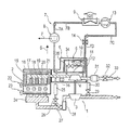
- FIGURE of the drawing shows a block diagram explaining the principles according to the invention.
- an exhaust turbocharger 1 of an internal combustion engine 2 comprising a compressor 3 and a turbine 4 , which is drive-connected to the compressor 3 and which is arranged in a turbine housing 5 .
- the turbine housing 5 is provided with an evaporator 6 , to which heat deriving from the exhaust gas temperature of the exhaust gases of the internal combustion engine 2 can be admitted in order to evaporate a working fluid and at least one temperature sensor 36 .
- the evaporator 6 comprises three evaporation ducts 10 , 11 and 12 , which carry the working fluid and which are flow-connected to a line arrangement 7 .
- a steam turbine 8 which is driven by the evaporated working fluid and delivers a power P, is arranged in a first line portion 7 A of the line arrangement 7 .
- a condenser 9 which recondenses the working fluid expanded in the steam turbine 8 to the liquid state and by way of a pump 13 pumps it into a line portion 7 C and into an adjoining line portion 7 D, is arranged downstream of the steam turbine 8 .
- a shut-off valve 14 is furthermore arranged in the line portion 7 D.
- the internal combustion engine 2 is provided with an exhaust manifold 15 , which is integrated into the cylinder head and which is in turn enclosed by coolant ducts 16 , 17 , 18 , 19 , 20 and 21 .
- these ducts can also be embodied as an evaporator and may be operatively connected to the line arrangement 7 and its components previously described, in order to allow the alternative or additional performance of a further working fluid cycle in the form of the Rankine process initially described.
Landscapes
- Engineering & Computer Science (AREA)
- Chemical & Material Sciences (AREA)
- Combustion & Propulsion (AREA)
- Mechanical Engineering (AREA)
- General Engineering & Computer Science (AREA)
- Supercharger (AREA)
Applications Claiming Priority (4)
| Application Number | Priority Date | Filing Date | Title |
|---|---|---|---|
| DE102010048142 | 2010-10-11 | ||
| DE102010048142 | 2010-10-11 | ||
| DE102010048142.4 | 2010-10-11 | ||
| PCT/US2011/055235 WO2012051062A2 (en) | 2010-10-11 | 2011-10-07 | Exhaust turbocharger of an internal combustion engine |
Publications (2)
| Publication Number | Publication Date |
|---|---|
| US20130195619A1 US20130195619A1 (en) | 2013-08-01 |
| US9500199B2 true US9500199B2 (en) | 2016-11-22 |
Family
ID=45938905
Family Applications (1)
| Application Number | Title | Priority Date | Filing Date |
|---|---|---|---|
| US13/876,865 Active 2032-10-15 US9500199B2 (en) | 2010-10-11 | 2011-10-07 | Exhaust turbocharger of an internal combustion engine |
Country Status (5)
| Country | Link |
|---|---|
| US (1) | US9500199B2 (ko) |
| KR (1) | KR101925423B1 (ko) |
| CN (1) | CN103154467B (ko) |
| DE (1) | DE112011102951B4 (ko) |
| WO (1) | WO2012051062A2 (ko) |
Cited By (1)
| Publication number | Priority date | Publication date | Assignee | Title |
|---|---|---|---|---|
| US10526959B2 (en) * | 2016-09-12 | 2020-01-07 | Hyundai Motor Company | Turbocharged engine coolant system |
Families Citing this family (7)
| Publication number | Priority date | Publication date | Assignee | Title |
|---|---|---|---|---|
| DE102012022676A1 (de) * | 2012-11-21 | 2014-05-22 | Voith Patent Gmbh | Verdampfer zur teilweisen oder vollständigen Verdampfung eines Flüssigkeitsstromes |
| US9657603B2 (en) | 2013-07-15 | 2017-05-23 | Volvo Truck Corporation | Internal combustion engine arrangement comprising a waste heat recovery system and process for controlling said system |
| KR101534701B1 (ko) * | 2013-12-06 | 2015-07-24 | 현대자동차 주식회사 | 알루미늄 터빈하우징을 갖는 엔진시스템 |
| US9506426B2 (en) * | 2014-03-24 | 2016-11-29 | Ford Global Technologies, Llc | Methods and systems for recycling engine feedgas cold-start emissions |
| CN106150627B (zh) * | 2015-03-27 | 2020-01-31 | 长城汽车股份有限公司 | 发动机组件及具有其的车辆 |
| DE102018205873B3 (de) | 2018-04-18 | 2019-08-08 | Ford Global Technologies, Llc | Abgaskrümmer mit Luftspaltisolierung |
| CN111120066A (zh) * | 2018-11-01 | 2020-05-08 | 上海汽车集团股份有限公司 | 车辆及其发动机冷却系统 |
Citations (15)
| Publication number | Priority date | Publication date | Assignee | Title |
|---|---|---|---|---|
| US1803436A (en) * | 1929-10-29 | 1931-05-05 | Ralph B Otwell | Combined heater and exhaust manifold |
| DE2614956B1 (de) * | 1976-04-02 | 1977-10-06 | Sulzer Ag | Zweitakt-kolbenbrennkraftmaschine |
| US4884406A (en) * | 1987-08-17 | 1989-12-05 | Isuzu Motors Limited | Turbocharger |
| US6209390B1 (en) * | 1999-05-14 | 2001-04-03 | Larue Gerald Duane | Turbocharger fatigue life monitor |
| US6513328B2 (en) * | 2000-05-23 | 2003-02-04 | Robert Bosch Gmbh | Internal combustion engine with cooling circuit and heating heat exchanger connected to it |
| US20040112054A1 (en) | 2001-06-26 | 2004-06-17 | Volvo Lastvagnar Ab | Exhaust turbine apparatus |
| US20040231330A1 (en) | 2001-10-09 | 2004-11-25 | Shigeru Ibaraki | Rankine cycle system and vehicle therewith |
| US7104120B2 (en) * | 2004-03-02 | 2006-09-12 | Caterpillar Inc. | Method and system of determining life of turbocharger |
| US20080116691A1 (en) | 2006-11-20 | 2008-05-22 | Yao-Chang Lin | Energy generating system |
| US20090211253A1 (en) * | 2005-06-16 | 2009-08-27 | Utc Power Corporation | Organic Rankine Cycle Mechanically and Thermally Coupled to an Engine Driving a Common Load |
| US20100146969A1 (en) * | 2006-03-15 | 2010-06-17 | Man Nutzfahrzeuge Ag | Vehicle or Stationary Power Plant Having a Turbocharged Internal Combustion Engine as a Drive Source |
| US20100146967A1 (en) | 2008-12-12 | 2010-06-17 | Alexander Simpson | Emission system, apparatus, and method |
| US20100199631A1 (en) | 2008-10-29 | 2010-08-12 | Vitkovice Power Engineering A.S. | Power production process with gas turbine from solid fuel and waste heat and the equipment for the performing of this process |
| US8621865B2 (en) * | 2010-05-04 | 2014-01-07 | Ford Global Technologies, Llc | Internal combustion engine with liquid-cooled turbine |
| US8881711B1 (en) * | 2013-09-03 | 2014-11-11 | Frank Raymond Jasper | Fuel system and components |
Family Cites Families (8)
| Publication number | Priority date | Publication date | Assignee | Title |
|---|---|---|---|---|
| US6530224B1 (en) * | 2001-03-28 | 2003-03-11 | General Electric Company | Gas turbine compressor inlet pressurization system and method for power augmentation |
| JP2003278598A (ja) * | 2002-03-20 | 2003-10-02 | Toyota Motor Corp | ランキンサイクルによる車輌の排熱回収方法及び装置 |
| JP2006194227A (ja) * | 2005-01-17 | 2006-07-27 | Toyota Motor Corp | 内燃機関用ターボ過給機 |
| JP2008019711A (ja) * | 2006-07-10 | 2008-01-31 | Toyota Motor Corp | 内燃機関の過給機システム |
| US7824099B2 (en) | 2007-11-29 | 2010-11-02 | Gm Global Technology Operations, Inc. | Accurate gas temperature estimation at transient conditions based on temperature sensor readings |
| EP2143925A1 (de) | 2008-07-11 | 2010-01-13 | Ford Global Technologies, LLC | Anordnung mit Zylinderkopf und Turbine |
| DE102008034680A1 (de) | 2008-07-25 | 2010-06-10 | Continental Mechanical Components Germany Gmbh | Gekühltes Turboladergehäuse mit einer oder mehreren Elektronikeinrichtungen |
| DE202010005708U1 (de) | 2010-06-24 | 2010-08-26 | Ford Global Technologies, LLC., Detroit | Brennkraftmaschine mit Zylinderkopf und Turbine |
-
2011
- 2011-10-07 WO PCT/US2011/055235 patent/WO2012051062A2/en active Application Filing
- 2011-10-07 KR KR1020137010756A patent/KR101925423B1/ko active IP Right Grant
- 2011-10-07 DE DE112011102951.9T patent/DE112011102951B4/de active Active
- 2011-10-07 CN CN201180046532.3A patent/CN103154467B/zh active Active
- 2011-10-07 US US13/876,865 patent/US9500199B2/en active Active
Patent Citations (16)
| Publication number | Priority date | Publication date | Assignee | Title |
|---|---|---|---|---|
| US1803436A (en) * | 1929-10-29 | 1931-05-05 | Ralph B Otwell | Combined heater and exhaust manifold |
| DE2614956B1 (de) * | 1976-04-02 | 1977-10-06 | Sulzer Ag | Zweitakt-kolbenbrennkraftmaschine |
| US4884406A (en) * | 1987-08-17 | 1989-12-05 | Isuzu Motors Limited | Turbocharger |
| US6209390B1 (en) * | 1999-05-14 | 2001-04-03 | Larue Gerald Duane | Turbocharger fatigue life monitor |
| US6513328B2 (en) * | 2000-05-23 | 2003-02-04 | Robert Bosch Gmbh | Internal combustion engine with cooling circuit and heating heat exchanger connected to it |
| US20040112054A1 (en) | 2001-06-26 | 2004-06-17 | Volvo Lastvagnar Ab | Exhaust turbine apparatus |
| US20040231330A1 (en) | 2001-10-09 | 2004-11-25 | Shigeru Ibaraki | Rankine cycle system and vehicle therewith |
| US7475541B2 (en) | 2001-10-09 | 2009-01-13 | Honda Giken Kogyo Kabushiki Kaisha | Rankine cycle system and vehicle therewith |
| US7104120B2 (en) * | 2004-03-02 | 2006-09-12 | Caterpillar Inc. | Method and system of determining life of turbocharger |
| US20090211253A1 (en) * | 2005-06-16 | 2009-08-27 | Utc Power Corporation | Organic Rankine Cycle Mechanically and Thermally Coupled to an Engine Driving a Common Load |
| US20100146969A1 (en) * | 2006-03-15 | 2010-06-17 | Man Nutzfahrzeuge Ag | Vehicle or Stationary Power Plant Having a Turbocharged Internal Combustion Engine as a Drive Source |
| US20080116691A1 (en) | 2006-11-20 | 2008-05-22 | Yao-Chang Lin | Energy generating system |
| US20100199631A1 (en) | 2008-10-29 | 2010-08-12 | Vitkovice Power Engineering A.S. | Power production process with gas turbine from solid fuel and waste heat and the equipment for the performing of this process |
| US20100146967A1 (en) | 2008-12-12 | 2010-06-17 | Alexander Simpson | Emission system, apparatus, and method |
| US8621865B2 (en) * | 2010-05-04 | 2014-01-07 | Ford Global Technologies, Llc | Internal combustion engine with liquid-cooled turbine |
| US8881711B1 (en) * | 2013-09-03 | 2014-11-11 | Frank Raymond Jasper | Fuel system and components |
Non-Patent Citations (3)
| Title |
|---|
| Chinese Office Action dated Jun. 9, 2015; Application No. 201180046532.3 ; Applicant : BorgWarner Inc.; 5 pages. |
| Chinese Office Action dated Sep. 28, 2014; Application No. 201180046532.3 ; Applicant : BorgWarner Inc.; 14 pages. |
| International Search Report and Written Opinion date of mailing May 2, 2012 : for Intemational Application No. PCT/US2011/056235 ; 9 pages. |
Cited By (1)
| Publication number | Priority date | Publication date | Assignee | Title |
|---|---|---|---|---|
| US10526959B2 (en) * | 2016-09-12 | 2020-01-07 | Hyundai Motor Company | Turbocharged engine coolant system |
Also Published As
| Publication number | Publication date |
|---|---|
| DE112011102951B4 (de) | 2021-07-22 |
| US20130195619A1 (en) | 2013-08-01 |
| WO2012051062A3 (en) | 2012-06-21 |
| WO2012051062A2 (en) | 2012-04-19 |
| CN103154467A (zh) | 2013-06-12 |
| KR20130122946A (ko) | 2013-11-11 |
| CN103154467B (zh) | 2015-09-30 |
| KR101925423B1 (ko) | 2019-02-27 |
| DE112011102951T5 (de) | 2013-07-04 |
Similar Documents
| Publication | Publication Date | Title |
|---|---|---|
| US9500199B2 (en) | Exhaust turbocharger of an internal combustion engine | |
| US8434307B2 (en) | Exhaust gas system and method for recovering energy | |
| US8601986B2 (en) | Split cooling method and apparatus | |
| EP3064733B1 (en) | Engine cooling system | |
| US8544274B2 (en) | Energy recovery system using an organic rankine cycle | |
| CN103154488B (zh) | 内燃机的废热利用装置 | |
| JP5221541B2 (ja) | 過給装置 | |
| DK178133B1 (da) | Stor turboladet dieselmotor med energigenvindingsindretning | |
| CN103237961B (zh) | 采用有机朗肯循环的排放临界增压冷却 | |
| AU2010224799B2 (en) | Method and apparatus for oiling rotating or oscillating components | |
| US8627662B2 (en) | Exhaust gas recirculation heat recovery system and method | |
| US9074492B2 (en) | Energy recovery arrangement having multiple heat sources | |
| JP7147229B2 (ja) | 廃熱利用システム | |
| JP5325254B2 (ja) | 定置用内燃機関の吸気冷却装置 | |
| CN104279032A (zh) | 用于机动车的驱动单元 | |
| CN201246214Y (zh) | 增质增压发动机 | |
| WO2008094071A3 (fr) | Procédé de fonctionnement et modèle de moteur combiné doté d'un corps de travail à deux phases basé sur un moteur à combustion interne à piston | |
| CN111527297B (zh) | 用于转换来自内燃机损失热的热能的装置 | |
| CN101555824B (zh) | 增质增压发动机 | |
| US11035270B2 (en) | Internal combustion engine having an exhaust heat recovery system as well as a method for recovering exhaust heat | |
| GB2463641A (en) | Making use of the waste heat from an internal combustion engine | |
| EP2527244A1 (en) | System and method for providing heat on a ship | |
| WO2011073718A2 (en) | Internal combustion engine arrangement with rankine circuit and hybrid cylinder, especially for an automotive vehicle | |
| GB2442006A (en) | Waste heat driven Stirling engine | |
| DK178371B1 (da) | Stor turboladet dieselmotor med energigenvindingsindretning |
Legal Events
| Date | Code | Title | Description |
|---|---|---|---|
| AS | Assignment |
Owner name: BORGWARNER INC., MICHIGAN Free format text: ASSIGNMENT OF ASSIGNORS INTEREST;ASSIGNOR:JOERGL, VOLKER;REEL/FRAME:030676/0996 Effective date: 20130622 |
|
| STCF | Information on status: patent grant |
Free format text: PATENTED CASE |
|
| MAFP | Maintenance fee payment |
Free format text: PAYMENT OF MAINTENANCE FEE, 4TH YEAR, LARGE ENTITY (ORIGINAL EVENT CODE: M1551); ENTITY STATUS OF PATENT OWNER: LARGE ENTITY Year of fee payment: 4 |
|
| MAFP | Maintenance fee payment |
Free format text: PAYMENT OF MAINTENANCE FEE, 8TH YEAR, LARGE ENTITY (ORIGINAL EVENT CODE: M1552); ENTITY STATUS OF PATENT OWNER: LARGE ENTITY Year of fee payment: 8 |