US9492935B2 - Apparatus for grooving cardboard cuttings - Google Patents
Apparatus for grooving cardboard cuttings Download PDFInfo
- Publication number
- US9492935B2 US9492935B2 US13/940,386 US201313940386A US9492935B2 US 9492935 B2 US9492935 B2 US 9492935B2 US 201313940386 A US201313940386 A US 201313940386A US 9492935 B2 US9492935 B2 US 9492935B2
- Authority
- US
- United States
- Prior art keywords
- cardboard
- transport drum
- outlet
- infeed
- drum
- Prior art date
- Legal status (The legal status is an assumption and is not a legal conclusion. Google has not performed a legal analysis and makes no representation as to the accuracy of the status listed.)
- Expired - Fee Related, expires
Links
Images


Classifications
-
- B—PERFORMING OPERATIONS; TRANSPORTING
- B26—HAND CUTTING TOOLS; CUTTING; SEVERING
- B26D—CUTTING; DETAILS COMMON TO MACHINES FOR PERFORATING, PUNCHING, CUTTING-OUT, STAMPING-OUT OR SEVERING
- B26D3/00—Cutting work characterised by the nature of the cut made; Apparatus therefor
- B26D3/06—Grooving involving removal of material from the surface of the work
- B26D3/065—On sheet material
-
- B31B1/25—
-
- B—PERFORMING OPERATIONS; TRANSPORTING
- B42—BOOKBINDING; ALBUMS; FILES; SPECIAL PRINTED MATTER
- B42C—BOOKBINDING
- B42C7/00—Manufacturing bookbinding cases or covers of books or loose-leaf binders
- B42C7/005—Creasing the back of covers
-
- B31B2201/25—
-
- B—PERFORMING OPERATIONS; TRANSPORTING
- B31—MAKING ARTICLES OF PAPER, CARDBOARD OR MATERIAL WORKED IN A MANNER ANALOGOUS TO PAPER; WORKING PAPER, CARDBOARD OR MATERIAL WORKED IN A MANNER ANALOGOUS TO PAPER
- B31B—MAKING CONTAINERS OF PAPER, CARDBOARD OR MATERIAL WORKED IN A MANNER ANALOGOUS TO PAPER
- B31B50/00—Making rigid or semi-rigid containers, e.g. boxes or cartons
- B31B50/25—Surface scoring
-
- Y—GENERAL TAGGING OF NEW TECHNOLOGICAL DEVELOPMENTS; GENERAL TAGGING OF CROSS-SECTIONAL TECHNOLOGIES SPANNING OVER SEVERAL SECTIONS OF THE IPC; TECHNICAL SUBJECTS COVERED BY FORMER USPC CROSS-REFERENCE ART COLLECTIONS [XRACs] AND DIGESTS
- Y10—TECHNICAL SUBJECTS COVERED BY FORMER USPC
- Y10T—TECHNICAL SUBJECTS COVERED BY FORMER US CLASSIFICATION
- Y10T83/00—Cutting
- Y10T83/02—Other than completely through work thickness
- Y10T83/0304—Grooving
Definitions
- the present invention pertains to an apparatus for grooving cardboard cuttings.
- Book cases, as well as boxes for high-quality sales and gift packages essentially consist of cardboards that are lined with cloth materials.
- the cardboard cuttings are grooved at the corresponding locations.
- the groove cross section may have any profile from triangular to rectangular that is cut out of the cardboards in the form of waste with knife blades that are accordingly aligned relative to one another or circular knives and, if applicable, an intermediately arranged lift-out device or with one-piece special knives that are shaped in accordance with the respective cross section.
- CN 101200091 B discloses a corresponding cardboard grooving machine, in which the infeed is situated at the upper vertex and the outlet is situated at the lower vertex of the transport drum, wherein said cardboard grooving machine has a common operating side for feeding and removing the cardboard cuttings and an opposite tool side. Due to the ground clearance required at the lower outlet for the stacking process and the relatively large drum diameter required for ensuring a flawless transport, the horse is elevated in such a way that the cardboard cuttings can only be fed from a pedestal while the grooved cardboard cuttings effectively need to be removed from the ground. Another disadvantage can be seen in that the cardboard cuttings are delivered with the grooved side on the bottom such that a continuous visual quality control cannot be carried out and the respective grooving result instead needs to be controlled by removing and turning individual cardboard cuttings.
- CN 102166834 A describes a cardboard grooving machine of the same type, in which the infeed is situated at the lower vertex of the transport drum, wherein the grooved cardboard cuttings are also ejected onto a delivery table on the opposite side with the grooved side on the bottom. Although the feed and the removal of the cardboard cuttings are ergonomically improved, access to the cutting tools for adjustments and corrections thereof is blocked by the delivery table.
- the object of the present invention is to provide a grooving apparatus, by means of which positionally accurate, cross-sectionally accurate and clean grooves can be cut into cardboard cuttings in a simple and user-friendly fashion.
- the outlet is situated in the region of the upper vertex of the transport drum such that the cut grooves of the cardboard cuttings being delivered point upward.
- the cut grooves are visible from above during the operation of the apparatus and the groove quality can be continuously assessed on any of the cardboards being delivered without having to remove individual cardboard cuttings.
- This also makes it possible, in particular, to detect any waste that might still remain on the cardboard or in the grooves. This waste can be simply blown away or brushed away because it is situated on the upper side of the cardboard rather than on its underside.
- the delivery of the cardboards with the grooves pointing upward furthermore allows the direct subsequent processing in downstream devices such as, e.g., a laminating machine, in which the cardboards are glued onto cloth materials with the groove-free bottom side, without having to turn over the cardboard cuttings.
- the delivery of the grooved cardboard cuttings at the upper vertex of the transport drum also results in an ergonomically advantageous removal height, in particular, if the cardboards are dropped from the outlet onto a delivery table arranged at a lower height.
- first rollers are arranged a certain distance in front of the outlet such that the belts have a segment that tangentially extends away from the transport drum. This makes it possible to significantly reduce an undesirable flexing and bending effect in the outlet and the cardboards are delivered in a nearly planar fashion.
- a further transport can also be realized in this way, for example, by means of a roller carpet arranged thereunder or by utilizing belts in the form of suction belts.
- the manual removal respectively can be further rationalized or prepared for a mechanized removal by providing a stacking device that is arranged downstream of the outlet and respectively forms or delivers a stack on a plane that lies lower than the outlet. Since the respective cardboard cutting grooved last lies on the top of the stack with the grooved side pointing upward, a visual quality control can be easily carried out during the stacking onto pallets without having to remove a cardboard cutting from the stack.
- the grooved cardboard cuttings are transported away by a conveyor belt that extends transverse to the outlet, for example, in order to transfer the cardboard cuttings to an adjoining coupled subsequent processing device. If the grooved cardboard cuttings are deposited and transported away on the conveyor belt in the form of an imbricated stream, in which the cardboard cuttings lie underneath one another toward the front, an effectively endless stack is formed that can be removed in arbitrary partial quantities independently of the machine cycle.
- the imbricated further transport allows a visual inspection of at least an area of the cut grooves on all cardboard cuttings.
- the feed to the infeed and the delivery from the outlet take place on the same side of the transport drum referred to a vertical plane defined by the drum axis such that a user-friendly feed and removal of the cardboard cuttings can be realized on a common operating side and the groove cutting tools can be arranged on the opposite tool side such that they are easily accessible and accumulating waste can be freely discharged.
- the infeed preferably is situated in the region of the lower vertex of the transport drum, wherein the cardboard cuttings are transported to the infeed by conveyor means in an essentially flat fashion.
- the cardboard cuttings are transported to the transport drum tangentially and received by the infeed in their flat orientation.
- the design with the infeed at the lower vertex and the outlet at the upper vertex results in a wrap angle of the belts around the transport drum of about 180° and therefore a sufficiently long transport section for positioning different cutting and processing tools that are arranged successively in the transport direction.
- a feed conveyor with cardboard pushers that push on the rear edge of the cardboards is preferably provided in order to transport the cardboard cuttings to the infeed with a slightly higher speed than the transport drum while they are laterally aligned on guide rails.
- the cardboard cuttings are exactly aligned on the rear edge and one lateral edge and effectively forced into the infeed between transport drum and belt in this orientation due to the excess speed.
- the processing is carried out in a cyclic fashion such that it is possible to respectively realize a direct transfer to and from synchronized upstream and downstream machines.
- Second rollers preferably are arranged a certain distance in front of the infeed such that the belts have a segment that tangentially extends toward the transport drum.
- the conveyor segment supports the alignment of the cardboard cuttings on the slightly faster moving cardboard pushers of the feed conveyor.
- a cardboard magazine for accommodating a stack of cardboard cuttings is provided, wherein the respective bottom cardboard cutting can be removed from said cardboard magazine and transported to the infeed. Further cardboards can then be fed to the grooving apparatus without being held at a higher and therefore ergonomically more advantageous infeed height.
- the cardboard magazine is realized in the form of a buffer that operates in accordance with the FiFo (First-in-First-out) principle and particularly advantageous for the coupling of the grooving apparatus to an upstream machine.
- the advantages of a further increased storage capacity and an additionally improved ergonomic infeed height are achieved by assigning the cardboard magazine a pre-stacking belt for receiving cardboard cuttings that are fed in an imbricated fashion or in the form of stacks, wherein said pre-stacking belt automatically feeds the cardboard cuttings to the cardboard magazine in accordance with the magazine filling level.
- two transport regions lie adjacent to one another on the transport drum and respectively feature at least one groove cutting tool such that a first and a second processing section with separate first and second infeeds and outlets are formed in the grooving apparatus.
- the double-crossed grooving can be further automated if the cardboard cuttings being delivered at the first outlet are automatically transferred to the second infeed while simultaneously being turned and/or turned over by transport and/or guide means.
- a gluing device with at least one application means arranged at a defined distance from the drum surface is provided.
- glue can be applied onto the grooved side of the cardboard cuttings during the transport on the transport drum in order to glue additional cardboard parts, cloth materials or the like onto the grooved cardboard cuttings immediately after the grooving process.
- Glue can be introduced into the previously cut grooves by an application means in the form of an application wheel or application nozzle that follows and is aligned with the at least one groove cutting tool such that the cardboard cutting can subsequently be folded and joined into a box without having to glue paper strips over the edges.
- circular knives are arranged upstream of the infeed and/or downstream of the outlet such that the cardboard cuttings can be simultaneously trimmed to the desired width and/or height during the groove cutting process.
- punching tools are arranged upstream of the infeed and/or downstream of the outlet such that corners and/or holes can be simultaneously punched out of the cardboard cuttings during the groove cutting process.
- the grooving apparatus is coupled to a downstream box folding and joining device or to an upstream or downstream laminating device, in which the cardboard cuttings are respectively lined with a blank to be covered on the outer side and/or inner side.
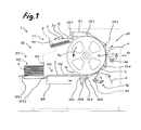
- FIG. 1 shows a schematic side view of a grooving apparatus
- FIG. 2 shows the grooving apparatus with a pre-stacking belt and a stacking device, as well as a gluing device;
- FIG. 3 shows the grooving apparatus with integrated cardboard cutting and punching devices
- FIG. 4 shows a partially schematic perspective representation of the grooving apparatus with two adjacent processing sections
- FIG. 4 a shows a cardboard cutting that was punched out in a cruciform and grooved in a double-crossed fashion
- FIG. 4 b shows a box
- FIG. 5 shows a schematic representation of a box production line
- FIG. 6 shows a groove cutting tool fitted with a grooving knife.
- the grooving apparatus 1 schematically illustrated in FIG. 1 comprises a driven, horizontally supported transport drum 11 and several spaced-apart endless belts 51 that revolve around rollers 54 . 1 to 54 . 8 and are partially wrapped around the transport drum 11 such that an infeed 14 and an outlet 15 are formed, as well as groove cutting tools 72 that are arranged between the belts 51 at a defined distance from the drum surface.
- Cardboard cuttings 2 transported to the infeed 14 by a feed device 101 are pressed onto the drum surface in an effectively conveying fashion by the belts 51 and transported from the infeed 14 situated at the lower vertex of the transport drum 11 to the outlet 15 situated at the upper vertex in the transport direction 11 a during an approximately 180° rotation of the transport drum 11 , wherein the cardboard cuttings are during this process guided past groove cutting tools 72 , at which, for example, a V-shaped waste section 6 is cut out of the cardboard cuttings 2 with correspondingly shaped grooving knives 71 .
- the feed device 101 in FIG. 1 features a cardboard magazine 102 that can be filled in an ergonomically advantageous fashion and contains a stack 4 of cardboard cuttings that lie on top of one another.
- the respective bottom cardboard cutting 2 is ejected underneath a front stop 103 by a first cardboard pusher 104 . 1 and transferred into an intermediate position 105 , from which the cardboard cutting 2 is transported to the infeed 14 by a second cardboard pusher 104 . 2 while being aligned on outer guide rails 106 .
- the cardboard pushers 104 . 1 , 104 . 2 are coupled at a fixed distance from one another and cyclically moved forward and backward with a constant transport stroke 107 that corresponds to this fixed distance. In this case, the transport speed is slightly higher than the rotational speed of the transport drum 11 such that the cardboard cuttings 2 effectively are forcibly pushed into the infeed 14 between transport drum 11 and belt 51 .
- the belts 51 Since the rollers 54 . 2 are arranged a certain distance in front of the infeed 14 , the belts 51 have a segment that tangentially extends toward the transport drum 11 . In this way, flexing and bending are significantly reduced in the infeed 14 . In addition, the segment supports the alignment of the cardboard cuttings 2 on the slightly faster moving cardboard pushers 104 . 2 of the feed device 101 .
- the delivery 111 in FIG. 1 features a delivery table 112 that downwardly slopes obliquely forward, wherein the completely grooved cardboard cuttings 3 exiting the outlet 15 are dropped onto the delivery table and placed on top of one another in order to form a stack 5 . Since the outlet 15 is arranged at the upper vertex of the transport drum 11 , the cut grooves 3 lie on the upper side of the exiting cardboard cuttings 3 . Consequently, the cut grooves 3 a are visible from above during the operation of the apparatus and the groove quality can be continuously assessed on any of the cardboards being delivered without having to remove individual cardboard cuttings 3 .
- the delivery of the grooved cardboard cuttings 3 at the upper vertex of a transport drum 11 and the depositing on the delivery table 112 arranged at a lower height furthermore result in an ergonomically advantageous removal height.
- the belts 51 Since the rollers 54 . 1 are arranged a certain distance in front of the outlet 15 , the belts 51 have a segment that tangentially extends away from the transport drum 11 . In this way, flexing and bending are significantly reduced in the outlet 15 and the grooved cardboard cuttings 3 are delivered in a nearly planar fashion.
- the delivery 111 and the feed device 101 lie on the same horizontal side of the transport drum 11 , namely the so-called operating side 66 , while the groove cutting tools 72 are situated on the opposite tool side 67 and freely accessible.
- FIG. 2 shows the grooving apparatus 1 with a pre-stacking belt 108 that is arranged upstream of the cardboard magazine 102 of the feed device 101 .
- the pre-stacking belt receives cardboard cuttings 2 in imbricated form or in stacks 4 a and automatically delivers these cardboard cuttings to the cardboard magazine 102 .
- the pre-stacking belt 108 provides a larger storage capacity and ergonomically improves the infeed height due to its higher transport plane.
- a stacking device 113 is furthermore provided in the delivery 111 of the grooving apparatus 1 according to FIG. 2 .
- the stacking device features a shaft 114 with a rake-like intermediate bottom 115 that can be opened and closed and a conveyor belt 116 that lies underneath this intermediate bottom and transports away the cardboard cuttings 3 lying on top of one another in the form of a stack 5 transverse to the transport direction 11 a .
- the segments of the belts 51 that tangentially and horizontally extend away from the transport drum 11 and pressure rollers 117 arranged thereunder jointly form an additional conveyor, by means of which the cardboard cuttings 3 being delivered are transported as far as the shaft 114 .
- the rollers 54 . 1 to 54 . 8 are arranged around the transport drum 11 in such a way that a total of three areas of closest approach between the belt outer segments that lie between the rollers 54 . 5 and 54 . 3 , 54 . 3 and 54 . 4 , 54 . 4 and 54 . 6 and the belt inner segments adjoining the transport drum 11 are formed in the exemplary embodiments.
- the groove cutting tools 72 and a gluing device 81 with adjacently arranged application nozzles 82 . 1 , 82 . 2 may be arranged between belts and adjacent to these areas.
- the gluing device 81 is described in greater detail further below.
- the groove cutting tools 72 are mounted on supporting beams 36 , 37 that lie parallel to the axis of transport drum 11 . Several groove cutting tools 72 may be mounted adjacent to one another on the same supporting beam. Grooves 3 a that lie very close to one another can be produced due to the arrangement on two supporting beams 36 , 37 that lie behind one another in the transport direction 11 a.
- FIG. 6 shows an example of a groove cutting tool 72 . It comprises a carrier 73 that can be fixed on the supporting beam 36 with a clamping block 74 that is actuated by means of a clamping screw 75 . A receptacle slide 76 for the grooving knife 71 provided with a dovetail guide 71 a mounted on the carrier 73 . After loosening the clamping block 74 , the groove cutting tool 72 can be displaced axially referred to the transport drum 11 such that the position of the groove 3 a to be cut in the cardboard cutting 3 can be changed.
- the receptacle slide 76 can be released and displaced in small increments radially referred to the transport drum 11 by means of a dial 77 such that the respective cutting depth can be adjusted.
- the grooving knife 71 ultimately can also be adjusted transverse to the two aforementioned adjusting directions by means of its dovetail guide 71 a.
- FIG. 3 shows the grooving apparatus 1 with a cardboard cutting device 91 that is integrated into the feed device 101 and features circular knives 92 that trim the cardboard cuttings 2 to the desired width and/or height by means of a shearing cut, as well as transport rollers 93 arranged upstream and downstream thereof. Furthermore, a punching device 96 is integrated into the delivery 111 and features one or more punching knives 97 that are moved vertically up and down, against a corresponding counter knife 98 , as well as an intermittently driven clamping belt conveyor 99 , by means of which the cardboard cuttings 3 received from the transport drum 11 are transferred into the respective punching position and subsequently transported away to the delivery table 112 .
- the punching device 96 makes it possible to punch corners and/or holes out of the cardboard cuttings 3 during the groove cutting process.
- the punching device 96 may also be integrated into the feed device 101 and the cardboard cutting device 91 may vice versa be arranged in the delivery 111 .
- FIG. 4 shows a partially schematic perspective representation of the grooving apparatus 1 , in the form of an embodiment with two processing sections 25 . 1 , 25 . 2 that lie adjacent to one another and respectively feature three parallel belts 51 that are spaced apart from one another, as well as groove cutting tools 72 . 1 , 72 . 2 and 72 . 3 , 72 . 4 arranged between the belts 51 .
- a gluing device 81 is provided in the second processing section 25 . 2 and features two application nozzles 82 . 1 , 82 . 2 that respectively are arranged downstream of and in alignment with the groove cutting tools 72 . 3 , 72 . 4 and apply glue 83 into the previously cut grooves 27 b.
- the grooving apparatus 1 illustrated in FIG. 4 makes it possible to groove cruciform punched cardboard cuttings 26 . 1 in a double-crossed fashion on one grooving apparatus 1 in immediately successive production steps.
- the cardboard cuttings 26 . 1 are fed to the transport drum 11 through the first infeed 14 . 1 and delivered at the first outlet 15 . 1 in the form of longitudinally grooved cardboard cuttings 26 . 2 featuring two grooves 27 a extending along the transport direction 11 a , wherein these cardboard cuttings are then transferred stack-by-stack from the receiving position 87 at the first outlet 15 . 1 into a delivery position 88 at the second infeed 14 . 2 by means of a pivoted gripper 86 , and wherein the cardboard cuttings 26 . 2 are once again individually removed from said delivery position and transported to the second processing section 25 . 2 , from which they emerge in the form of cardboard cuttings 26 . 3 grooved in a double-crossed fashion at the second outlet 15 . 2 .
- the cardboard cuttings 26 . 2 are turned and turned over by the pivoted gripper 86 that pivots about a horizontal pivoting axis 89 that is inclined relative to the drum axis by 45° in such a way that the grooved side, which still lies on the top at the first outlet 15 . 1 , once again lies on the bottom at the second infeed 14 . 2 and the already produced grooves 27 a are oriented transverse to the transport direction 11 a .
- the longitudinally grooved cardboard cuttings 26 . 2 may also be manually transferred from the first outlet 15 . 1 to the second infeed 14 . 2 .
- FIG. 4 a shows a flat cardboard cutting 26 . 3 that was grooved with V-grooves 27 a , 27 b in a double-crossed fashion.
- the grooves 27 b produced in the second processing section 25 . 2 are provided with a glue application 83 .
- a box 28 of the type illustrated in FIG. 4 b is formed by folding the sidewalls 29 a to 29 d arranged around a bottom 29 e in the cardboard cutting 26 . 3 into an upright position, wherein the respectively joined edges of the sidewalls 29 a to 29 d form a miter joint 30 that is glued together by the glue application 83 .
- the box 28 is joined without gluing paper strips over the edges.
- the box 28 that is lined with a cover in a subsequent processing step therefore does not feature any uneven regions caused by such paper strips and also has sharp outer edges.
- FIG. 5 shows a schematic representation of a box production line 121 consisting of a laminating device 122 that glues the entire surface of a blank to be covered 126 onto a cardboard cutting 125 and folds over its edges, a punching device 123 for punching the corners out of the lined cardboard cutting 127 , the grooving apparatus 1 according to FIG. 4 for grooving the cruciform cardboard cutting 128 in a double-crossed fashion and a box folding and joining device 124 for folding and joining the grooved cardboard cutting 129 into a box 130 .
- the laminating device 122 and/or the punching device 123 may also be arranged downstream of the grooving apparatus 1 in the box production line 121 .
Applications Claiming Priority (3)
| Application Number | Priority Date | Filing Date | Title |
|---|---|---|---|
| DE102012013807.5 | 2012-07-12 | ||
| DE201210013807 DE102012013807A1 (de) | 2012-07-12 | 2012-07-12 | Vorrichtung zum Nuten von Pappenzuschnitten |
| DE102012013807 | 2012-07-12 |
Publications (2)
| Publication Number | Publication Date |
|---|---|
| US20140013919A1 US20140013919A1 (en) | 2014-01-16 |
| US9492935B2 true US9492935B2 (en) | 2016-11-15 |
Family
ID=48190053
Family Applications (1)
| Application Number | Title | Priority Date | Filing Date |
|---|---|---|---|
| US13/940,386 Expired - Fee Related US9492935B2 (en) | 2012-07-12 | 2013-07-12 | Apparatus for grooving cardboard cuttings |
Country Status (7)
| Country | Link |
|---|---|
| US (1) | US9492935B2 (ja) |
| EP (1) | EP2684683B1 (ja) |
| JP (1) | JP6161440B2 (ja) |
| CN (1) | CN103538284B (ja) |
| DE (1) | DE102012013807A1 (ja) |
| ES (1) | ES2672722T3 (ja) |
| PL (1) | PL2684683T3 (ja) |
Families Citing this family (50)
| Publication number | Priority date | Publication date | Assignee | Title |
|---|---|---|---|---|
| US8460773B2 (en) * | 2005-11-15 | 2013-06-11 | Web To Print For You, Ltd. | Detachable sheet |
| UA109938C2 (uk) | 2011-05-06 | 2015-10-26 | Механічна фіксуюча система для будівельних панелей | |
| CN105518316B (zh) | 2013-09-16 | 2019-03-29 | 瓦林格创新股份有限公司 | 组合产品和装配该组合产品的方法 |
| US9726210B2 (en) | 2013-09-16 | 2017-08-08 | Valinge Innovation Ab | Assembled product and a method of assembling the product |
| US9714672B2 (en) | 2014-01-10 | 2017-07-25 | Valinge Innovation Ab | Panels comprising a mechanical locking device and an assembled product comprising the panels |
| MX2016014501A (es) | 2014-05-09 | 2017-01-23 | Vaelinge Innovation Ab | Sistema de bloqueo mecanico para paneles de construccion. |
| RU2709003C2 (ru) | 2014-12-19 | 2019-12-12 | Велинге Инновейшн Аб | Панели, содержащие запирающее устройство, и собранное изделие, содержащее панели |
| WO2016171607A1 (en) | 2015-04-21 | 2016-10-27 | Välinge Innovation AB | Panel with a slider |
| KR20170141223A (ko) | 2015-04-30 | 2017-12-22 | 뵈린게 이노베이션 에이비이 | 체결 디바이스를 갖는 패널 |
| DE102015012228A1 (de) | 2015-09-18 | 2017-03-23 | Kolbus Gmbh & Co. Kg | Vorrichtung zum Nuten von Materialbogen |
| UA125554C2 (uk) | 2015-09-22 | 2022-04-20 | Велінге Інновейшн Аб | Панелі, що містять механічний фіксуючий пристрій, і зібраний виріб, що містить панелі |
| ES2894363T3 (es) | 2015-12-03 | 2022-02-14 | Vaelinge Innovation Ab | Conjunto de paneles que comprende un dispositivo de bloqueo mecánico |
| BR112018014151B1 (pt) | 2016-01-26 | 2022-12-27 | Vãlinge Innovation Ab | Conjunto de painéis compreendendo um dispositivo de bloqueio mecânico |
| KR20180109957A (ko) | 2016-02-04 | 2018-10-08 | 뵈린게 이노베이션 에이비이 | 조립된 제품을 위한 패널들의 세트 |
| US10486245B2 (en) | 2016-02-09 | 2019-11-26 | Valinge Innovation Ab | Element and method for providing dismantling groove |
| CA3011612A1 (en) | 2016-02-09 | 2017-08-17 | Valinge Innovation Ab | A set of three panel-shaped elements |
| MX2018009631A (es) * | 2016-02-15 | 2018-12-17 | Vaelinge Innovation Ab | Un metodo para formar un panel para un producto de mobiliario. |
| DE102016002905A1 (de) | 2016-03-09 | 2017-09-14 | Kolbus Gmbh & Co. Kg | Verfahren und Vorrichtung zum Nuten von Pappenzuschnitten |
| DE102016003798A1 (de) | 2016-03-26 | 2017-09-28 | Kolbus Gmbh & Co. Kg | Werkzeug, Vorrichtung und Verfahren zum Schneiden in Pappenzuschnitte |
| US10724564B2 (en) | 2016-10-27 | 2020-07-28 | Valinge Innovation Ab | Set of panels with a mechanical locking device |
| CN107053759B (zh) * | 2017-05-12 | 2023-06-13 | 广州荣欣包装制品有限公司 | 一种纸盒加工吸尘装置 |
| US11506235B2 (en) | 2017-05-15 | 2022-11-22 | Valinge Innovation Ab | Elements and a locking device for an assembled product |
| WO2019125291A1 (en) | 2017-12-22 | 2019-06-27 | Välinge Innovation AB | A set of panels, a method for assembly of the same and a locking device for a furniture product |
| EP3728869B1 (en) | 2017-12-22 | 2023-01-25 | Välinge Innovation AB | A set of panels, a method for assembly of the same and a locking device for a furniture product |
| CN108422712A (zh) * | 2018-03-03 | 2018-08-21 | 兰州交通大学 | 一种纸纱复合袋的压痕、切口装置 |
| WO2019182505A1 (en) | 2018-03-23 | 2019-09-26 | Välinge Innovation AB | Panels comprising a mechanical locking device and an assembled product comprising the panels |
| CN112262265B (zh) | 2018-04-18 | 2022-12-20 | 瓦林格创新股份有限公司 | 对称榫舌和t形交叉组件 |
| US11076691B2 (en) | 2018-04-18 | 2021-08-03 | Valinge Innovation Ab | Set of panels with a mechanical locking device |
| EP3781824B1 (en) | 2018-04-18 | 2024-04-10 | Välinge Innovation AB | Set of panels with a mechanical locking device |
| CN112119226B (zh) | 2018-04-18 | 2022-05-27 | 瓦林格创新股份有限公司 | 具有机械锁定装置的镶板组 |
| US11614114B2 (en) | 2018-04-19 | 2023-03-28 | Valinge Innovation Ab | Panels for an assembled product |
| CN108466453A (zh) * | 2018-05-07 | 2018-08-31 | 浙江赛力机械有限公司 | 双向纸板开槽机 |
| BR112021002370A2 (pt) | 2018-08-30 | 2021-05-11 | Välinge Innovation AB | conjunto de painéis com um dispositivo de travamento mecânico |
| CN109702811B (zh) * | 2019-01-22 | 2020-10-16 | 宁夏成峰包装印刷有限公司 | 可人工介入操作的环动模切机 |
| CN109732989B (zh) * | 2019-02-26 | 2023-05-23 | 龙口锦昇包装有限公司 | 一种纸托盘底角快速定位全自动包角机 |
| CN110587031B (zh) * | 2019-08-22 | 2021-04-09 | 合肥国轩高科动力能源有限公司 | 一种用于圆柱电池回收的拆解设备 |
| CN110435214B (zh) * | 2019-09-13 | 2021-06-29 | 浙江赛力机械有限公司 | 一种新型双向纸板开槽机 |
| CN110961235B (zh) * | 2019-11-29 | 2020-07-31 | 天津职业技术师范大学(中国职业培训指导教师进修中心) | 一种切削屑回收处理装置 |
| CN110948938A (zh) * | 2019-12-10 | 2020-04-03 | 合肥迅达包装股份有限公司 | 一种纸品包装糊盒机 |
| CN111604987A (zh) * | 2020-05-15 | 2020-09-01 | 浙江赛力机械有限公司 | 双向纸板分切机 |
| CN111674878A (zh) * | 2020-06-22 | 2020-09-18 | 嘉兴卓尔精密机械有限公司 | 一种板式构件转向移送装置 |
| CN112318591B (zh) * | 2020-10-29 | 2022-07-12 | 浙江赛力智能制造有限公司 | 一种纸板开槽刀具、纸板开槽机以及纸板开槽方法 |
| CN112554260B (zh) * | 2020-12-27 | 2022-08-09 | 郑素花 | 一种水利开槽机 |
| CN113306197A (zh) * | 2021-06-07 | 2021-08-27 | 朱梁帅 | 一种瓦楞纸板的压痕方法和压痕设备 |
| CN113334852B (zh) * | 2021-06-07 | 2023-04-11 | 钜丰智能科技有限公司 | 一种适用不同厚度瓦楞纸板的压痕设备 |
| CN113352700A (zh) * | 2021-07-06 | 2021-09-07 | 安徽世品佳工业产品设计有限公司 | 纸板导料压痕装置 |
| CN113334854A (zh) * | 2021-07-06 | 2021-09-03 | 安徽世品佳工业产品设计有限公司 | 纸板导料压痕方法 |
| US20230101990A1 (en) * | 2021-09-24 | 2023-03-30 | Graphic Packaging International, Llc | Methods And Systems For Preparing Blanks For Forming Carriers For Containers |
| CN114212515A (zh) * | 2022-02-23 | 2022-03-22 | 深圳熙卓科技有限公司 | 一种检测外观的质检机设备 |
| CN116852427A (zh) * | 2023-07-11 | 2023-10-10 | 浙江赛力智能制造有限公司 | 一种送料切割机构及纸板分切机 |
Citations (22)
| Publication number | Priority date | Publication date | Assignee | Title |
|---|---|---|---|---|
| US1289271A (en) | 1915-11-10 | 1918-12-31 | Hoe & Co R | Scoring mechanism for cardboard and similar material. |
| US2240765A (en) | 1939-06-28 | 1941-05-06 | Armstrong Cork Co | Device for grooving preformed sheets |
| US2500338A (en) * | 1947-08-04 | 1950-03-14 | Bergstein Samuel | Manufacture of transparent knockdown containers |
| US3550509A (en) * | 1968-02-23 | 1970-12-29 | American Envelope Co | Method and apparatus of high-speed manufacture of flap glued lined envelope |
| US4221373A (en) * | 1977-03-18 | 1980-09-09 | Grapha-Holding Ag | Apparatus for folding paper sheets or the like |
| US4793227A (en) * | 1987-06-15 | 1988-12-27 | Stobb Inc. | Apparatus and method for trimming signatures |
| US5921752A (en) * | 1997-04-24 | 1999-07-13 | Dickinson Press, Inc. | Flat spine scorer and saddle stitcher |
| US6029884A (en) * | 1998-05-26 | 2000-02-29 | Paul T. Trend Corporation | Method for constructing a sturdy, light-tight package and a package thereof |
| US20020022560A1 (en) * | 2000-04-27 | 2002-02-21 | Michael Zoeckler | Paperboard cartons with laminated reinforcing ribbons and method of printing same |
| US6360514B1 (en) * | 1998-10-15 | 2002-03-26 | R. R. Donnelley & Sons Company | Method for bulk cartooning of books |
| US20020061240A1 (en) * | 2000-11-21 | 2002-05-23 | Kolbus Gmbh & Co. Kg. | Device for manufacturing book-binding covers |
| US20020059979A1 (en) * | 2000-11-21 | 2002-05-23 | Kolbus Gmbh & Co. Kg. | Apparatus for feeding spine inserts for the mechanical manufacture of book covers |
| US6478725B1 (en) * | 1998-04-29 | 2002-11-12 | Emba Machinery Ab | Slitting unit for carton blank production |
| US6547231B1 (en) * | 2000-04-13 | 2003-04-15 | Usa Leader, Llc | Apparatus for placing inserts of different thicknesses and widths into newspaper jackets |
| US20040138037A1 (en) * | 2001-04-23 | 2004-07-15 | Karl-Heinz Kruger | Machine for the production of ready-glued folding boxes arranged in a planar manner |
| US7201089B2 (en) * | 2001-10-09 | 2007-04-10 | Heidelberger Druckmaschinen Ag | Feeder, gatherer-stitcher and method for index punching |
| US20080108490A1 (en) * | 2004-03-19 | 2008-05-08 | Kocherga Michael E | Method and apparatus for forming corrugated board carton blanks |
| CN101200091A (zh) * | 2007-11-15 | 2008-06-18 | 陈自力 | 一种纸板起槽机 |
| US7537557B2 (en) * | 2006-04-10 | 2009-05-26 | Müller Martini Holding AG | Folder feeder |
| CN102166834A (zh) | 2011-01-19 | 2011-08-31 | 吴凡 | 滚筒式纸板钩槽机 |
| CN201970485U (zh) | 2011-02-24 | 2011-09-14 | 东莞市鸿铭机械有限公司 | 纸盒成型机的开槽角度调整机构 |
| CN202412794U (zh) | 2012-01-11 | 2012-09-05 | 郑如朋 | 一种便于操作、安全的开槽机 |
Family Cites Families (4)
| Publication number | Priority date | Publication date | Assignee | Title |
|---|---|---|---|---|
| JPS56133151A (en) * | 1980-03-24 | 1981-10-19 | Shinko Kikai Seisakusho Kk | Method and device for supplying corrugated cardboard sheet in can manufacturing machine |
| JP2807711B2 (ja) * | 1990-03-20 | 1998-10-08 | 株式会社林原生物化学研究所 | カートンブランクの繰出し装置 |
| JPH0624634A (ja) * | 1992-07-09 | 1994-02-01 | Toshiba Seiki Kk | 丁合物補給装置 |
| JP2006150735A (ja) * | 2004-11-29 | 2006-06-15 | Casio Comput Co Ltd | 容器作成装置、容器作成システム |
-
2012
- 2012-07-12 DE DE201210013807 patent/DE102012013807A1/de not_active Withdrawn
-
2013
- 2013-04-25 ES ES13002178.5T patent/ES2672722T3/es active Active
- 2013-04-25 PL PL13002178T patent/PL2684683T3/pl unknown
- 2013-04-25 EP EP13002178.5A patent/EP2684683B1/de not_active Not-in-force
- 2013-06-05 CN CN201310220111.9A patent/CN103538284B/zh not_active Expired - Fee Related
- 2013-07-12 JP JP2013146062A patent/JP6161440B2/ja not_active Expired - Fee Related
- 2013-07-12 US US13/940,386 patent/US9492935B2/en not_active Expired - Fee Related
Patent Citations (23)
| Publication number | Priority date | Publication date | Assignee | Title |
|---|---|---|---|---|
| US1289271A (en) | 1915-11-10 | 1918-12-31 | Hoe & Co R | Scoring mechanism for cardboard and similar material. |
| US2240765A (en) | 1939-06-28 | 1941-05-06 | Armstrong Cork Co | Device for grooving preformed sheets |
| US2500338A (en) * | 1947-08-04 | 1950-03-14 | Bergstein Samuel | Manufacture of transparent knockdown containers |
| US3550509A (en) * | 1968-02-23 | 1970-12-29 | American Envelope Co | Method and apparatus of high-speed manufacture of flap glued lined envelope |
| US4221373A (en) * | 1977-03-18 | 1980-09-09 | Grapha-Holding Ag | Apparatus for folding paper sheets or the like |
| US4793227A (en) * | 1987-06-15 | 1988-12-27 | Stobb Inc. | Apparatus and method for trimming signatures |
| US5921752A (en) * | 1997-04-24 | 1999-07-13 | Dickinson Press, Inc. | Flat spine scorer and saddle stitcher |
| US6478725B1 (en) * | 1998-04-29 | 2002-11-12 | Emba Machinery Ab | Slitting unit for carton blank production |
| US6029884A (en) * | 1998-05-26 | 2000-02-29 | Paul T. Trend Corporation | Method for constructing a sturdy, light-tight package and a package thereof |
| US6360514B1 (en) * | 1998-10-15 | 2002-03-26 | R. R. Donnelley & Sons Company | Method for bulk cartooning of books |
| US6547231B1 (en) * | 2000-04-13 | 2003-04-15 | Usa Leader, Llc | Apparatus for placing inserts of different thicknesses and widths into newspaper jackets |
| US20020022560A1 (en) * | 2000-04-27 | 2002-02-21 | Michael Zoeckler | Paperboard cartons with laminated reinforcing ribbons and method of printing same |
| US20020061240A1 (en) * | 2000-11-21 | 2002-05-23 | Kolbus Gmbh & Co. Kg. | Device for manufacturing book-binding covers |
| US20020059979A1 (en) * | 2000-11-21 | 2002-05-23 | Kolbus Gmbh & Co. Kg. | Apparatus for feeding spine inserts for the mechanical manufacture of book covers |
| US20040138037A1 (en) * | 2001-04-23 | 2004-07-15 | Karl-Heinz Kruger | Machine for the production of ready-glued folding boxes arranged in a planar manner |
| US7201089B2 (en) * | 2001-10-09 | 2007-04-10 | Heidelberger Druckmaschinen Ag | Feeder, gatherer-stitcher and method for index punching |
| US20080108490A1 (en) * | 2004-03-19 | 2008-05-08 | Kocherga Michael E | Method and apparatus for forming corrugated board carton blanks |
| US7537557B2 (en) * | 2006-04-10 | 2009-05-26 | Müller Martini Holding AG | Folder feeder |
| CN101200091A (zh) * | 2007-11-15 | 2008-06-18 | 陈自力 | 一种纸板起槽机 |
| CN101200091B (zh) | 2007-11-15 | 2010-08-11 | 陈自力 | 一种纸板起槽机 |
| CN102166834A (zh) | 2011-01-19 | 2011-08-31 | 吴凡 | 滚筒式纸板钩槽机 |
| CN201970485U (zh) | 2011-02-24 | 2011-09-14 | 东莞市鸿铭机械有限公司 | 纸盒成型机的开槽角度调整机构 |
| CN202412794U (zh) | 2012-01-11 | 2012-09-05 | 郑如朋 | 一种便于操作、安全的开槽机 |
Also Published As
| Publication number | Publication date |
|---|---|
| DE102012013807A1 (de) | 2014-05-15 |
| EP2684683A1 (de) | 2014-01-15 |
| JP6161440B2 (ja) | 2017-07-12 |
| ES2672722T3 (es) | 2018-06-15 |
| CN103538284B (zh) | 2017-09-12 |
| US20140013919A1 (en) | 2014-01-16 |
| CN103538284A (zh) | 2014-01-29 |
| EP2684683B1 (de) | 2018-03-07 |
| PL2684683T3 (pl) | 2018-08-31 |
| JP2014019161A (ja) | 2014-02-03 |
Similar Documents
| Publication | Publication Date | Title |
|---|---|---|
| US9492935B2 (en) | Apparatus for grooving cardboard cuttings | |
| EP1359092A1 (en) | Method and device for turning over stacks of products on a cartoning machine | |
| US5203953A (en) | Process and apparatus for conveying labels to be transferred to a (cigarette) pack | |
| US20140069253A1 (en) | Apparatus for Grooving Cardboard Cuttings | |
| CN111032515B (zh) | 用于将物品自动包装在纸板盒中的设备 | |
| US6843473B2 (en) | Apparatus for manufacturing book covers | |
| CN110303545B (zh) | A4纸双回旋刀切纸、令纸生产和箱包装一体生产线 | |
| CN110271894B (zh) | A4纸双回旋刀切纸令纸生产线 | |
| JP4253147B2 (ja) | 製本用表紙を製造する装置 | |
| US6279302B1 (en) | Sheet-interposing device for automatic slicing machine | |
| HRP990160A2 (en) | Apparatus and method for producing and packing foil bags | |
| JP2004009736A (ja) | はじき出し装置付きの折り畳み箱用接着機械 | |
| US20070209752A1 (en) | Method and device for feeding a cover | |
| US6601844B2 (en) | Procedure for feeding products in sheet form to a conveyor and pick up unit | |
| CA2118692A1 (en) | Slitting corrugated paperboard boxes | |
| CN208247580U (zh) | 双向纸板开槽机 | |
| KR100385704B1 (ko) | 음료병 포장용 상자 폴딩장치 | |
| CN114174072B (zh) | 用于自动化生产书装订封皮和/或盒盖的设备和方法 | |
| KR102380336B1 (ko) | 핸드 타월 제조를 위한 자동화 공정 시스템 | |
| CN213650039U (zh) | 自适应包装系统 | |
| JPS5859153A (ja) | 平板体の積重ね機構 | |
| US8801351B2 (en) | Device for cutting to length and feeding spine strips for a case maker | |
| WO2022219437A1 (en) | Apparatus for continuous production of tailored, pre-folded blanks of corrugated cardboard | |
| US20100215472A1 (en) | Device and method for depositing continually stacked flat material pieces | |
| SE542933C2 (sv) | Anordning för automatisk emballering av föremål av varierande storlek. |
Legal Events
| Date | Code | Title | Description |
|---|---|---|---|
| AS | Assignment |
Owner name: KOLBUS GMBH & CO. KG, GERMANY Free format text: ASSIGNMENT OF ASSIGNORS INTEREST;ASSIGNORS:GERKE, KLAUS;LINTELMANN, GERHARD;UGORETS, LEONID;REEL/FRAME:030785/0084 Effective date: 20130704 |
|
| STCF | Information on status: patent grant |
Free format text: PATENTED CASE |
|
| FEPP | Fee payment procedure |
Free format text: MAINTENANCE FEE REMINDER MAILED (ORIGINAL EVENT CODE: REM.); ENTITY STATUS OF PATENT OWNER: LARGE ENTITY |
|
| LAPS | Lapse for failure to pay maintenance fees |
Free format text: PATENT EXPIRED FOR FAILURE TO PAY MAINTENANCE FEES (ORIGINAL EVENT CODE: EXP.); ENTITY STATUS OF PATENT OWNER: LARGE ENTITY |
|
| STCH | Information on status: patent discontinuation |
Free format text: PATENT EXPIRED DUE TO NONPAYMENT OF MAINTENANCE FEES UNDER 37 CFR 1.362 |
|
| FP | Lapsed due to failure to pay maintenance fee |
Effective date: 20201115 |