US9487083B2 - Fuel supply apparatus - Google Patents
Fuel supply apparatus Download PDFInfo
- Publication number
- US9487083B2 US9487083B2 US14/259,700 US201414259700A US9487083B2 US 9487083 B2 US9487083 B2 US 9487083B2 US 201414259700 A US201414259700 A US 201414259700A US 9487083 B2 US9487083 B2 US 9487083B2
- Authority
- US
- United States
- Prior art keywords
- forming member
- passage forming
- injection port
- passage
- fuel
- Prior art date
- Legal status (The legal status is an assumption and is not a legal conclusion. Google has not performed a legal analysis and makes no representation as to the accuracy of the status listed.)
- Expired - Fee Related, expires
Links
Images


Classifications
-
- B—PERFORMING OPERATIONS; TRANSPORTING
- B60—VEHICLES IN GENERAL
- B60K—ARRANGEMENT OR MOUNTING OF PROPULSION UNITS OR OF TRANSMISSIONS IN VEHICLES; ARRANGEMENT OR MOUNTING OF PLURAL DIVERSE PRIME-MOVERS IN VEHICLES; AUXILIARY DRIVES FOR VEHICLES; INSTRUMENTATION OR DASHBOARDS FOR VEHICLES; ARRANGEMENTS IN CONNECTION WITH COOLING, AIR INTAKE, GAS EXHAUST OR FUEL SUPPLY OF PROPULSION UNITS IN VEHICLES
- B60K15/00—Arrangement in connection with fuel supply of combustion engines or other fuel consuming energy converters, e.g. fuel cells; Mounting or construction of fuel tanks
- B60K15/03—Fuel tanks
- B60K15/04—Tank inlets
-
- B—PERFORMING OPERATIONS; TRANSPORTING
- B60—VEHICLES IN GENERAL
- B60K—ARRANGEMENT OR MOUNTING OF PROPULSION UNITS OR OF TRANSMISSIONS IN VEHICLES; ARRANGEMENT OR MOUNTING OF PLURAL DIVERSE PRIME-MOVERS IN VEHICLES; AUXILIARY DRIVES FOR VEHICLES; INSTRUMENTATION OR DASHBOARDS FOR VEHICLES; ARRANGEMENTS IN CONNECTION WITH COOLING, AIR INTAKE, GAS EXHAUST OR FUEL SUPPLY OF PROPULSION UNITS IN VEHICLES
- B60K15/00—Arrangement in connection with fuel supply of combustion engines or other fuel consuming energy converters, e.g. fuel cells; Mounting or construction of fuel tanks
- B60K15/03—Fuel tanks
- B60K15/035—Fuel tanks characterised by venting means
- B60K2015/03523—Arrangements of the venting tube
- B60K2015/03538—Arrangements of the venting tube the venting tube being connected with the filler tube
-
- B—PERFORMING OPERATIONS; TRANSPORTING
- B60—VEHICLES IN GENERAL
- B60K—ARRANGEMENT OR MOUNTING OF PROPULSION UNITS OR OF TRANSMISSIONS IN VEHICLES; ARRANGEMENT OR MOUNTING OF PLURAL DIVERSE PRIME-MOVERS IN VEHICLES; AUXILIARY DRIVES FOR VEHICLES; INSTRUMENTATION OR DASHBOARDS FOR VEHICLES; ARRANGEMENTS IN CONNECTION WITH COOLING, AIR INTAKE, GAS EXHAUST OR FUEL SUPPLY OF PROPULSION UNITS IN VEHICLES
- B60K15/00—Arrangement in connection with fuel supply of combustion engines or other fuel consuming energy converters, e.g. fuel cells; Mounting or construction of fuel tanks
- B60K15/03—Fuel tanks
- B60K15/04—Tank inlets
- B60K2015/0458—Details of the tank inlet
- B60K2015/0461—Details of the tank inlet comprising a filler pipe shutter, e.g. trap, door or flap for fuel inlet
-
- B—PERFORMING OPERATIONS; TRANSPORTING
- B60—VEHICLES IN GENERAL
- B60K—ARRANGEMENT OR MOUNTING OF PROPULSION UNITS OR OF TRANSMISSIONS IN VEHICLES; ARRANGEMENT OR MOUNTING OF PLURAL DIVERSE PRIME-MOVERS IN VEHICLES; AUXILIARY DRIVES FOR VEHICLES; INSTRUMENTATION OR DASHBOARDS FOR VEHICLES; ARRANGEMENTS IN CONNECTION WITH COOLING, AIR INTAKE, GAS EXHAUST OR FUEL SUPPLY OF PROPULSION UNITS IN VEHICLES
- B60K15/00—Arrangement in connection with fuel supply of combustion engines or other fuel consuming energy converters, e.g. fuel cells; Mounting or construction of fuel tanks
- B60K15/03—Fuel tanks
- B60K15/04—Tank inlets
- B60K2015/0458—Details of the tank inlet
- B60K2015/047—Manufacturing of the fuel inlet or connecting elements to fuel inlet, e.g. pipes or venting tubes
Definitions
- the present invention relates to a fuel supply apparatus including a fuel passage for guiding fuel to a fuel tank.
- the filler neck has a pipe body made of a resin, a cap for opening and closing an opening of the pipe body, an inner member mounted in the pipe body, and a flap valve for opening and closing an injection port provided on the inner member.
- An outer perimeter of the inner member is welded and fixed to the pipe body, thereby sealing between the inner member and the pipe body is sealed.
- the present invention is directed to solve at least parts of the above problems, and can be embodied as the following aspects or applications.
- a fuel supply apparatus for supplying fuel to a fuel tank includes a passage forming member that has a fuel passage connected to the fuel tank, an injection port forming member that is disposed in the fuel passage and fixed to the passage forming member, the injection port forming member having an injection port forming a part of the fuel passage, and an injection port open and close mechanism that is openably and closably mounted to the injection port forming member and has an open and close member for opening and closing the injection port.
- the passage forming member and the injection port forming member are formed of resin materials welded to each other and the passage forming member and the injection port forming member are welded at a welded portion along an entire perimeter thereof to seal a gap between the passage forming member and the injection port forming member.
- the passage forming member has a reinforcing member arranged in an annular shape along the entire perimeter of the passage forming member.
- the reinforcing member is formed of a material having a mechanical strength higher than the passage forming member.
- the reinforcing member and the welded portion are arranged in the vicinity of a common plane perpendicular to a center line of the fuel passage.
- the passage forming member has the reinforcing member arranged in an annular shape along the entire circumference thereof.
- the reinforcing member and the welded portion are arranged on the common plane perpendicular to the center line of the fuel passage.
- the reinforcing member is formed of a material having a mechanical strength higher than the passage forming member. Therefore, even if a vehicle collides or the like and thus an external force due to collision of the vehicle or the like is exerted on the vicinity of the welded portion of the passage forming member, the reinforcing member can mitigate an impact on the vicinity of the welded portion or the injection port forming member, thereby protecting a sealed region. Thus, during collision of the vehicle, a fuel in the fuel tank can be prevented from being discharged to the outside.
- the reinforcing member is formed of a metallic material.
- the passage forming member has a flange portion formed on an opened end of the passage forming member by enlarging a diameter of the end of the passage forming member toward an outer perimeter thereof, and the reinforcing member is mounted on the flange portion and arranged at a location spaced from the welded portion toward the outer perimeter.
- the passage forming member has an inner resin layer having a pipe shape for forming the fuel passage and formed of a first resin material, and an outer resin layer stacked on an outer surface of the inner resin layer and formed of a second resin material.
- the first resin material and the second resin material is configured so that one layer is formed of a resin material having a fuel permeation-resistance better than that of the other layer.
- the flange portion is formed on an end of either the inner resin layer or the outer resin layer.
- the passage forming member has a supporting portion formed on an opened end of the passage forming member and protruding from an end of the passage forming member toward an inner perimeter thereof, and the reinforcing member is mounted to the supporting portion.
- the fuel supply apparatus of any one of (1) to (5) further includes a cover member mounted to an upper part of the passage forming member to cover the injection port open and close mechanism.
- the cover member has a cup shape surrounded by a side wall portion and a top wall extending from a perimeter edge of the side wall portion, and has an engaging claw formed on the side wall portion.
- the engaging claw is engaged with the flange portion and thus the cover member is mounted to the passage forming member.
- the reinforcing member is provided to be located more toward an inner perimeter than the welded portion and to be adjacent to the welded portion.
- a fuel supply apparatus for supplying fuel to a fuel tank includes a passage forming member that has a fuel passage connected to the fuel tank, an injection port forming member that is disposed in the fuel passage and fixed to the passage forming member, the injection port forming member having an injection port constituting a part of the fuel passage, and an injection port open and close mechanism that is openably and closably mounted to the injection port forming member and has an open and close member for opening and closing the injection port.
- the passage forming member and the injection port forming member are formed of resin materials welded to each other and the passage forming member and the injection port forming member are welded at a welded portion along an entire circumference thereof to seal a gap between the passage forming member and the injection port forming member.
- the passage forming member has an external force absorption portion arranged in an annular shape along the entire circumference of the passage forming member, and the external force absorption portion is located more toward an outer perimeter than a region provided with the welded portion and is arranged with a gap.
- the external force absorption portion is configured to be elastically deformed in a direction, in which the gap is narrowed, when an external force F is exerted thereon.
- the gap and the welded portion are arranged on a common plane perpendicular to a center line of the fuel passage.
- the gap is formed between an end surface on an inner perimeter side of the flange portion and an end of the injection port forming member. If an external force is exerted on the flange portion, an extension portion is bended to reduce the gap, and thus an influence of the external force on the welded portion can be mitigated.
- the passage forming member has a flange portion formed on an opened end of the passage forming member by enlarging a diameter of the end of the passage forming member toward an outer perimeter thereof, and the external force absorption portion is formed on the flange portion.
- the passage forming member has an inner resin layer having a pipe shape for forming the fuel passage and formed of a first resin material, and an outer resin layer stacked on an outer surface of the inner resin layer and formed of a second resin material.
- the first resin material and the second resin material is configured so that one layer is formed of a resin material having a fuel permeation-resistance better than that of the other layer.
- the flange portion is formed on an end of either the inner resin layer or the outer resin layer.
- the fuel supply apparatus of (9) or (10) further includes a cover member mounted to an upper part of the passage forming member to cover the injection port open and close mechanism.
- the cover member has a cup shape surrounded by a side wall portion and a top wall, and has an engaging claw formed on the side wall portion. The engaging claw is engaged with the flange portion and thus the cover member is mounted to the passage forming member.
- FIG. 1 is a sectional view showing a fuel supply apparatus using a filler neck according to a first embodiment of the present invention.
- FIG. 2 is a sectional view showing the fuel supply apparatus whose parts have been exploded.
- FIG. 3 is an enlarged sectional view showing an upper part of the fuel supply apparatus whose parts have been exploded.
- FIG. 4 is an enlarged sectional view showing a main part of the fuel supply apparatus according to FIG. 1 .
- FIG. 5 is a sectional view showing a state where a cover member in FIG. 4 has been removed from a passage forming member.
- FIG. 6 is a sectional view showing main parts of a passage forming member and an injection port forming member according to a variant of the first embodiment.
- FIG. 7 is a sectional view showing main parts of a passage forming member and an injection port forming member according to another variant.
- FIG. 8 is a sectional view showing main parts of a passage forming member and an injection port forming member according to a variant in which a part of a configuration of the variant of FIG. 7 are modified.
- FIG. 9 is a sectional view showing main parts of a passage forming member and an injection port forming member according to a further variant.
- FIG. 10 is a sectional view showing main parts of a passage forming member and an injection port forming member according to a second embodiment.
- FIG. 11 is a sectional view showing main parts of a passage forming member and an injection port forming member according to a variant of the second embodiment of FIG. 10 .
- FIG. 12 is a sectional view showing a passage forming member and an injection port forming member according to another variant of the second embodiment.
- FIG. 1 is a sectional view showing a fuel supply apparatus 10 using a filler neck according to a first embodiment of the present invention.
- the fuel supply apparatus 10 includes a tank opening forming member 11 having a fuel passage 11 P connected to a fuel tank (not shown), an insertion-side open and close mechanism 50 , and an injection port open and close mechanism 60 .
- the fuel supply apparatus 10 is configured so that, when the insertion-side open and close mechanism 50 and the injection port open and close mechanism 60 is pressed and opened by a fuel supply nozzle and then fuel is injected from the fuel supply nozzle to the fuel passage 11 P, the fuel is supplied to the fuel tank through the fuel passage 11 P.
- configuration of each part will be described.
- the tank opening forming member 11 is a tubular body forming the fuel passage 11 P and has a passage forming member 20 , an insertion passage forming member 30 , and an injection port forming member 40 .
- FIG. 2 is a sectional view showing the fuel supply apparatus whose parts have been exploded.
- the passage forming member 20 is formed by stacking two types of resin materials and has a cylindrical shaped neck body 21 , a neck connection portion 22 , and a breather tube 23 .
- the neck connection portion 22 which is integrally formed by enlarging a diameter of a lower part of the neck body 21 , is a cylindrical body constituting a part of the fuel passage 11 P and has an annular protrusion 22 a on an outer perimeter thereof.
- a tube TB (see FIG. 1 ) is inserted into the neck connection portion 22 , and thus, the tube TB is connected to the neck connection 22 by the annular protrusion 22 a in a separation-prevented state.
- the breather tube 23 is a tubular body branched from a side wall of the neck body 21 and an inner side thereof defines a breather passage 23 P.
- the breather passage 23 P is connected to the fuel tank, so that fuel vapor inside the fuel tank during supplying fuel is diverted to the neck body 21 , thereby allowing a smooth fuel supplying.
- the passage forming member 20 is constituted by stacking two types of resin materials and has an inner resin layer 27 located toward the fuel passage 11 P and an outer resin layer 28 stacked on an outer surface of the inner resin layer 27 .
- the inner resin layer 27 is formed of a resin material having a good fuel permeation-resistance, for example, polyamide (PA) such as nylon, ethylene vinyl alcohol copolymer (EVOH) or the like, and mainly acts as a barrier layer for inhibiting permeation of fuel.
- PA polyamide
- EVOH ethylene vinyl alcohol copolymer
- the outer resin layer 28 is formed of a resin material having a good mechanical strength, for example, polyethylene (PE) or the like, and mainly acts as a layer for ensuring mechanical strength and impact resistance of the passage forming member 20 .
- a resin material modified polyethylene modified by maleic acid as a polar functional group may be used.
- the modified polyethylene is bonded with PA by chemical adhesion, and thus adhered to the inner resin layer 27 .
- the insertion passage forming member 30 has a cover member 32 .
- the cover member 32 is mounted on an upper part of the passage forming member 20 and has a cylindrical side wall portion 32 a and a top wall 32 b .
- the side wall portion 32 has an inclined upper part, to which the top wall 32 b is integrally formed.
- the top wall 32 b has an opening portion 32 d for inserting a fuel supply nozzle.
- the opening portion 32 d has an insertion opening 32 e and a shaft supporting portion 32 f .
- the insertion opening 32 e has a generally circular shape to allow insertion of the fuel supply nozzle and constitutes a part of the fuel passage 11 P.
- the shaft supporting portion 32 f which is formed on an inner wall of the side wall portion 32 a , is a portion for mounting and supporting an end of the insertion-side open and close mechanism 50 .
- a passage forming member 34 is formed inside the cover member 32 .
- the passage forming member 34 is a member for defining an insertion passage 11 Pa, which is a part of the fuel passage 11 P, to insert and guide the fuel supply nozzle, and has an inclined wall 34 a .
- the inclined wall 34 a has a conical shape in which a passage area thereof is narrowed toward the fuel tank.
- the injection port forming member 40 is a member for supporting the injection port open and close mechanism 60 and has an opening portion 41 and a cylindrical supporting member 42 protruding from a lower surface of an outer perimeter of the opening portion 41 and received in the neck body 21 .
- the opening portion 41 has an injection port 41 a .
- the injection port 41 a is a generally circular passage for inserting the fuel supply nozzle and constitutes a part of the fuel passage 11 P.
- FIG. 3 is an enlarged sectional view showing an upper part of the fuel supply apparatus 10 whose parts have been exploded.
- the insertion-side open and close mechanism 50 has an open and close member 51 , a bearing portion 52 , and a spring 53 for urging the open and close member 51 toward a closing direction.
- the open and close member 51 is pushed by a distal end of the fuel supply nozzle and thus pivoted about the bearing portion 52 , thereby opening the insertion opening 32 e .
- a seal member 54 is disposed on an opening perimeter edge of the insertion opening 32 e .
- the open and close member 51 closes the insertion opening 32 e in a sealed state by pressing the seal member 54 .
- the injection port open and close mechanism 60 has an open and close member 61 , a bearing portion 62 interposed between the open and close member 61 and the injection port forming member 40 for pivotally supporting the open and close member 61 to the injection port forming member 40 , a spring 63 for urging the open and close member 61 toward a closing direction, a gasket 64 , and a pressure regulating valve 65 .
- the open and close member 61 has a pressing member 61 a and a valve chamber forming member 61 b and forms a valve chamber for receiving the pressure regulating member 65 .
- the gasket 64 which is formed in an annular shape by a rubber material, is mounted on an outer perimeter portion of the open and close member 61 and is held between the outer perimeter portion and a perimeter edge of the injection port 41 a , thereby closing the injection port 41 in a sealed state.
- the pressure regulating valve 65 which is received in the valve chamber, has a positive pressure valve urged by a spring and is a valve which, when a pressure of the fuel tank exceeds a predetermined pressure, is opened to relieve the pressure on the fuel tank side.
- FIG. 4 is an enlarged sectional view showing a main part of the fuel supply apparatus 10 according to FIG. 1
- FIG. 5 is a sectional view showing a state where the cover member 32 in FIG. 4 has been removed from the passage forming member 20
- a flange portion 24 is formed on the upper part of the passage forming member 20
- a retaining recessed portion 24 a is formed in an upper surface of the flange portion 24 over the entire perimeter thereof.
- a reinforcing member 25 is fixed to the retaining recessed portion 24 a using insert molding or the like.
- the reinforcing member 25 is an annular member formed of a metallic material, such as stainless steel.
- An engaging claw 32 g is formed on a lower part of the side wall portion 32 a of the cover member 32 .
- the engaging claw 32 g is engaged with the flange portion 24 , thereby mounting the cover member 32 to the passage forming member 20 .
- a flange-shaped attaching portion 32 j is formed on an outer perimeter portion of the cover member 32 .
- the attaching portion 32 j is fixed to a vehicle body-side substrate BP by a fastening member, such as a bolt.
- a flange portion 43 is formed on an upper part of the injection port forming member 40 .
- a lower surface of the flange portion 43 is welded on a welding end 21 a of the inner resin layer 27 .
- a welded portion Wd is formed using a laser welding method as a welding method.
- the welded portion Wd and the reinforcing member 25 are arranged on a common plane perpendicular to a center line CL of the fuel passage.
- the common plane HP is not limited to a plane, which fully includes the welded portion Wd and the reinforcing member 25 , but may be slightly deviated in a direction of the center axis, in other words means a region including the vicinity of the common plane.
- the passage forming member 20 and the insertion passage forming member 30 are first manufactured by injection molding.
- the passage forming member 20 is manufactured by performing two-color injection molding using two types of resin materials.
- Modified polyethylene for forming the outer resin layer 28 is injected as an initial resin material, and then polyamide for forming the inner resin layer 27 is injected.
- the modified polyethylene is a resin material in which a polar function group, for example, a functional group modified by maleic acid is added to polyethylene (PE), and is reactively adhered to the polyamide (PA) by a heat during injection molding. Therefore, the inner resin layer 27 and the outer resin layer 28 are welded and integrated with each other by a reactive adhesion using two-color molding.
- the insertion passage forming member 30 and the injection port forming member 40 are injection molded using polyethylene and polyamide, respectively.
- the outer resin layer 28 may contain carbon black of 0.1 to 2.0 parts by weight to enhance absorption of laser light.
- a laser irradiation apparatus is oriented to the flange portion 43 and the welding end 21 a of the neck body 21 and irradiates laser light to a bonding region between the flange portion 43 and the welding end 21 a while rotating the supporting table, on which the passage forming member 20 is supported.
- the welding end 21 a contains carbon black of 0.1 to 2.0 parts by weight and thus is melted by absorbing the laser light and also causes an inner surface of the flange portion 43 to be melted. Resin materials of such melted parts are the same resin material (PA) and therefore are compatible to each other and also welded to each other by cooling and solidifying.
- the insertion passage forming member 30 is mounted to the cover member 32 and the injection port forming member 40 is mounted to the injection port open and close mechanism 60 . Then, the engaging claw 32 g of the cover member 32 is engaged with the flange portion 24 to mount the cover member 32 , to which the insertion-side open and close mechanism 50 is mounted, to the passage forming member 20 . As a result, the fuel supply apparatus 10 as shown in FIG. 1 is obtained.
- the injection port open and close mechanism 60 is mounted in the passage forming member 20 with interposing the injection port forming member 40 therebetween.
- the injection port 41 a of the injection port forming member 40 is opened and closed by the open and close member 61 . Because the injection port forming member 40 is welded at the welded portion Wd to the passage forming member 20 over the entire perimeter thereof to seal therebetween, a higher sealing ability can be achieved without using a seal member, such an O-ring.
- the passage forming member 20 has the reinforcing member 25 arranged in an annular shape along the entire perimeter thereof.
- the reinforcing member 25 and the welded portion Wd are arranged on the common plane HP perpendicular to the center line CL of the fuel passage 11 P.
- the reinforcing member 25 is formed of a material having a mechanical strength higher than the passage forming member 20 . Therefore, even if a vehicle collides or the like and thus an external force F due to collision of the vehicle or the like is exerted on the vicinity of the welded portion Wd of the passage forming member 20 , the reinforcing member 25 can mitigate an impact on the vicinity of the welded portion Wd or the injection port forming member 40 , thereby protecting a sealed region. Thus, during collision of the vehicle, a fuel in the fuel tank can be prevented from being discharged to the outside.
- the reinforcing member 25 is mounted on the flange portion 24 formed on an opened end of the passage forming member 20 by enlarging a diameter of the end of the passage forming member 20 toward the outer perimeter.
- the passage forming member 20 is formed of two types of different resin materials, namely, the inner resin layer 27 is formed of polyamide having a good fuel permeation-resistance and the outer resin layer 28 is formed of polyethylene having good mechanical strength and impact resistance.
- the outer resin layer 28 can firmly hold the reinforcing member 25 utilizing the characteristics thereof in mechanical strength.
- the cover member 32 is mounted to the upper part of the passage forming member 20 to cover the injection port open and close mechanism 60 .
- the cover member 32 is mounted to the passage forming member by engaging the engaging claw 32 g of the cover member 32 with the flange portion 24 . Therefore, even if an external force is exerted on the cover member 32 during collision of the vehicle or the like, the cover member 32 is separated from the passage forming member 20 to absorb impact energy, and therefore the injection port open and close mechanism 60 and the injection port forming member 40 are hardly damaged.
- the flange portion 24 is increased in mechanical strength by the reinforcing member 25 , an impact exerted on the welded portion Wd from the cover member 32 can be reduced.
- FIG. 6 is a sectional view showing a main part of a passage forming member 20 B according to a variant of the first embodiment.
- the present variant is characterized in a shape of the passage forming member 20 B and arrangement of a reinforcing member 25 B.
- the passage forming member 20 B is constituted by stacking an inner resin layer 27 B and an outer resin layer 28 B.
- a flange portion 24 B is formed on an upper end of the inner resin layer 27 B.
- the reinforcing member 25 B is mounted to the flange portion 24 B.
- a flange portion 43 B of an injection port forming member 40 B is welded at a welded portion Wd.
- the reinforcing member 25 B is arranged to be aligned on a common plane of the welded portion Wd perpendicular to a center line of the fuel passage 11 P. Because the flange portion 24 B is integrally formed with the inner resin layer 27 B formed of polyamide, it is possible to firmly mount the reinforcing member 25 B to the inner resin layer 27 B utilizing a good thermal adhesion of the inner resin layer 27 to a metallic material.
- FIG. 7 is a sectional view showing main parts of a passage forming member 20 C and an injection port forming member 40 C according to another variant.
- the present variant is characterized in a shape of the passage forming member 20 C and arrangement of a reinforcing member 25 C.
- a recessed portion 24 Ca is formed in an inner wall of an upper part of an inner resin layer 27 C.
- the cylindrical reinforcing member 25 C elongated in an upward and downward direction in the figure is mounted.
- the reinforcing member 25 C is arranged to be more adjacent to an inner perimeter side of the passage forming member 20 C relative to a welded portion Wd.
- the reinforcing member 25 C can also enhance a function of protecting an injection open and close mechanism (see FIG. 3 ) from an external force, in addition to a function of preventing occurrences of problems, such as a breakage of the vicinity of the welded portion Wd due to an external force F.
- FIG. 8 is a sectional view showing main parts of a passage forming member 20 D and an injection port forming member 40 D according to a variant in which parts of the variant of FIG. 7 are modified.
- the present variant is characterized in a shape of the passage forming member 20 D and arrangement of reinforcing members 25 D and 24 D- 2 .
- a supporting portion 27 Da protruding to an inner perimeter side thereof is formed.
- An upper surface of the supporting portion 27 Da is welded to an upper part of the injection port forming member 40 D at a welded portion Wd.
- a retaining recessed portion 24 Da is defined by an outer wall of the upper part of the inner resin layer 27 D and an upper end of the outer resin layer 28 D.
- the cylindrical reinforcing member 25 D elongated in an upward and downward direction is mounted in the retaining recessed portion 24 Da. Also, the reinforcing member 25 D- 2 is mounted in a retaining recessed portion 24 Da- 2 of an upper part of the supporting portion 27 Da.
- the reinforcing member 25 D- 2 is also an annular metallic body.
- the upper end of the reinforcing member 25 D is arranged slightly below a plane HP including the welded portion Wd.
- the welded portion Wd and the reinforcing member 25 D may be slightly deviated in a direction of the center axis if being arranged in the vicinity of the common plane HP, and even with such arrangement, the reinforcing member 25 D exhibits an effect of reinforcing the welded portion Wd.
- the reinforcing members 25 D and 25 D- 2 are not limited to a single unit, but may be appropriately arranged in plurality.
- FIG. 9 is a sectional view showing main parts of a passage forming member 20 E and an injection port forming member 40 E according to a further variant.
- the present variant is characterized in a shape of a flange portion 24 E.
- the passage forming member 20 E has an inner resin layer 27 E and an outer resin layer 28 E.
- the flange portion 24 E protrudes radially outwardly from an end of the inner resin layer 27 .
- a reinforcing member 25 E is formed in an annular shape having a U-shaped cross section to surround the flange portion 24 E. In this way, the reinforcing member 25 E can have various shapes, considering a mechanical strength effective to protect a welded portion Wd, a mounting ability to the flange portion 24 E and the like.
- FIG. 10 is a sectional view showing main parts of a passage forming member 20 F and an injection port forming member 40 F according to a second embodiment.
- the passage forming member 20 F has an inner resin layer 27 F and an outer resin layer 28 F.
- a flange portion 43 F of the injection port forming member 40 F is welded.
- a flange portion 24 F is formed on an end of the outer resin layer 28 F.
- An upper end of the outer resin layer 28 F has an external force absorption portion 24 Fb arranged in an annular shape along the entire perimeter of the passage forming member 20 F.
- the external force absorption portion 24 Fb is located more toward an outer perimeter than a region provided with a welded portion Wd, and is arranged to be spaced from an end surface of the flange portion 43 F of the injection port forming member 40 F between interposing a gap Gp therebetween.
- the external force absorption portion 24 Fb is configured to be elastically deformed in a direction, in which the gap Gp is narrowed, when an external force F is exerted thereon.
- the gap Gp and the welded portion Wd are arranged on a common plane HP perpendicular to a center line CL of the fuel passage 11 P.
- a cover member 32 F has a flange portion 36 F having a welding surface 36 Fa.
- the flange portion 36 F is welded at a welded portion Wdl to either the flange portion 24 Fa or the flange portion 43 F of the injection port forming member 40 F, or both.
- the external force absorption portion 24 Fb can also protect the welded portion Wdl in such a region.
- FIG. 11 is a sectional view showing main parts of a passage forming member 20 G and an injection port forming member 40 F according to a variant of the second embodiment of FIG. 10 .
- the present variant is characterized in a configuration in which an end of a cover member 32 G is fixed to an outer resin layer 28 G as compared to the second embodiment of FIG. 10 .
- a welded portion Wd is spaced from the cover member 32 G with interposing a gap Gp 2 therebetween, and thus there is a feature in which an impact exerted on the cover member 32 G is hardly transferred to the welded portion Wd.
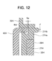
- FIG. 12 is a sectional view showing a passage forming member 20 H and an injection port forming member 40 H according to another variant of the second embodiment.
- the present variant is characterized in a configuration in which an external force absorption portion 21 Hb is provided on an inner resin layer 27 H, as compared to the variant of FIG. 10 .
- the passage forming member 20 H has the inner resin layer 27 H and an outer resin layer 28 H.
- An L-shaped extension portion 27 Ha is formed on an upper part of the inner resin layer 27 H and an external force absorption portion 21 Hb as a part of a flange portion 24 H is also formed on an outer perimeter of the extension portion 27 Ha.
- a gap Gp is formed between an end surface on an inner perimeter side of the flange portion 24 H and an end of the injection port forming member 40 H. If an external force E is exerted on the flange portion 24 H, the extension portion 27 Ha is bended to reduce the gap Gp, and thus an influence of the external force F on a welded portion Wd can be mitigated. Meanwhile, instead of the configuration in which the cover member 32 H is welded to the injection port forming member 40 H or the external force absorption portion 21 Hb, the cover member 32 H may be engaged with the passage forming member 20 H, similarly to the first embodiment.
- the prevent invention is not limited to such a configuration, but it is sufficient if a material thereof has a mechanical strength higher than the passage forming member, and accordingly, for example, a material or the like, in which glass fillers are added to a resin material, may be used.
- the passage forming member is constituted by stacking layers made of two types of resin materials, the invention is not limited to such a configuration, but the passage forming member may be formed in a single layer and the reinforcing member and the external force absorption portion may be provided on an end of the single layer. Also, both of the external force absorption portion and the reinforcing member may be provided, instead of configurations, which either one thereof is provided.
- each of the insertion passage forming member 30 and the injection port forming member 40 is formed in a single layer, is described in the first embodiment, the present invention is not limited to such a configuration, but a configuration, in which two or more types of resin materials are stacked on one another, may be employed or single layer and multi-layer configurations may be appropriately combined for each member.
- the welded portion is formed by laser welding in the foregoing embodiments, the invention is not limited to such a configuration, but other means, such as heat plate welding, may be employed.
Landscapes
- Engineering & Computer Science (AREA)
- Life Sciences & Earth Sciences (AREA)
- Sustainable Development (AREA)
- Sustainable Energy (AREA)
- Chemical & Material Sciences (AREA)
- Combustion & Propulsion (AREA)
- Transportation (AREA)
- Mechanical Engineering (AREA)
- Cooling, Air Intake And Gas Exhaust, And Fuel Tank Arrangements In Propulsion Units (AREA)
- Fuel-Injection Apparatus (AREA)
Applications Claiming Priority (2)
| Application Number | Priority Date | Filing Date | Title |
|---|---|---|---|
| JP2013093531A JP5983521B2 (ja) | 2013-04-26 | 2013-04-26 | 給油装置 |
| JP2013-093531 | 2013-04-26 |
Publications (2)
| Publication Number | Publication Date |
|---|---|
| US20140319161A1 US20140319161A1 (en) | 2014-10-30 |
| US9487083B2 true US9487083B2 (en) | 2016-11-08 |
Family
ID=51788404
Family Applications (1)
| Application Number | Title | Priority Date | Filing Date |
|---|---|---|---|
| US14/259,700 Expired - Fee Related US9487083B2 (en) | 2013-04-26 | 2014-04-23 | Fuel supply apparatus |
Country Status (2)
| Country | Link |
|---|---|
| US (1) | US9487083B2 (enExample) |
| JP (1) | JP5983521B2 (enExample) |
Cited By (2)
| Publication number | Priority date | Publication date | Assignee | Title |
|---|---|---|---|---|
| US20160185212A1 (en) * | 2014-12-26 | 2016-06-30 | Toyoda Gosei Co., Ltd. | Fueling device |
| US20170362074A1 (en) * | 2016-06-21 | 2017-12-21 | Honda Motor Co., Ltd. | Fuel supply structure for filler pipe |
Families Citing this family (6)
| Publication number | Priority date | Publication date | Assignee | Title |
|---|---|---|---|---|
| DE102012013824A1 (de) * | 2012-07-13 | 2014-01-16 | Illinois Tool Works Inc. | Einfüllstutzen für das Einfüllen von Kraftstoff in einem Fahrzeugtank eines Automobils |
| JP6572620B2 (ja) * | 2015-05-11 | 2019-09-11 | 豊田合成株式会社 | 燃料給油装置 |
| US11014441B2 (en) * | 2016-01-15 | 2021-05-25 | Stant Usa Corp. | Closure assembly for fuel-tank filler neck |
| JP6629628B2 (ja) | 2016-02-22 | 2020-01-15 | 住友理工株式会社 | キャップレス給油装置及びその製造方法 |
| JP6595369B2 (ja) * | 2016-02-26 | 2019-10-23 | 住友理工株式会社 | キャップレス給油口 |
| JP6488272B2 (ja) * | 2016-12-15 | 2019-03-20 | 本田技研工業株式会社 | 燃料供給管の給油部構造 |
Citations (6)
| Publication number | Priority date | Publication date | Assignee | Title |
|---|---|---|---|---|
| JPS6062327U (ja) | 1983-10-06 | 1985-05-01 | 山川工業株式会社 | 自動車用フイラ−チユ−ブ |
| JPH04108035A (ja) | 1990-08-24 | 1992-04-09 | Toyoda Gosei Co Ltd | 燃料注入口 |
| JPH11321350A (ja) | 1998-05-11 | 1999-11-24 | Unipres Corp | フィラーチューブの構造 |
| JP2001088858A (ja) | 1999-09-22 | 2001-04-03 | Toyoda Gosei Co Ltd | 燃料タンクの給油装置 |
| US20020092581A1 (en) | 1999-09-22 | 2002-07-18 | Toyoda Gosei Co., Ltd. | Fueling device |
| US20030075221A1 (en) * | 2001-10-03 | 2003-04-24 | Beaulne Michael A. | Fuel refilling assembly |
-
2013
- 2013-04-26 JP JP2013093531A patent/JP5983521B2/ja not_active Expired - Fee Related
-
2014
- 2014-04-23 US US14/259,700 patent/US9487083B2/en not_active Expired - Fee Related
Patent Citations (7)
| Publication number | Priority date | Publication date | Assignee | Title |
|---|---|---|---|---|
| JPS6062327U (ja) | 1983-10-06 | 1985-05-01 | 山川工業株式会社 | 自動車用フイラ−チユ−ブ |
| JPH04108035A (ja) | 1990-08-24 | 1992-04-09 | Toyoda Gosei Co Ltd | 燃料注入口 |
| JPH11321350A (ja) | 1998-05-11 | 1999-11-24 | Unipres Corp | フィラーチューブの構造 |
| JP2001088858A (ja) | 1999-09-22 | 2001-04-03 | Toyoda Gosei Co Ltd | 燃料タンクの給油装置 |
| US20020092581A1 (en) | 1999-09-22 | 2002-07-18 | Toyoda Gosei Co., Ltd. | Fueling device |
| US6681817B2 (en) | 1999-09-22 | 2004-01-27 | Toyoda Gosei Co., Ltd. | Fueling device |
| US20030075221A1 (en) * | 2001-10-03 | 2003-04-24 | Beaulne Michael A. | Fuel refilling assembly |
Non-Patent Citations (1)
| Title |
|---|
| Office Action issued Mar. 8, 2016 in the corresponding JP application No. 2013-093531 (with English translation). |
Cited By (4)
| Publication number | Priority date | Publication date | Assignee | Title |
|---|---|---|---|---|
| US20160185212A1 (en) * | 2014-12-26 | 2016-06-30 | Toyoda Gosei Co., Ltd. | Fueling device |
| US10093175B2 (en) * | 2014-12-26 | 2018-10-09 | Toyoda Gosei Co., Ltd. | Fueling device |
| US20170362074A1 (en) * | 2016-06-21 | 2017-12-21 | Honda Motor Co., Ltd. | Fuel supply structure for filler pipe |
| US10633242B2 (en) * | 2016-06-21 | 2020-04-28 | Honda Motor Co., Ltd. | Fuel supply structure for filler pipe |
Also Published As
| Publication number | Publication date |
|---|---|
| JP2014213761A (ja) | 2014-11-17 |
| US20140319161A1 (en) | 2014-10-30 |
| JP5983521B2 (ja) | 2016-08-31 |
Similar Documents
| Publication | Publication Date | Title |
|---|---|---|
| US9487083B2 (en) | Fuel supply apparatus | |
| JP6201845B2 (ja) | 燃料供給装置 | |
| JP5880374B2 (ja) | フィラーネック | |
| KR102153866B1 (ko) | 자동차용 액체 컨테이너 및 액체 컨테이너를 제조하기 위한 방법 | |
| US9394157B2 (en) | Fueling device and manufacturing method of a fueling device | |
| US20050211298A1 (en) | Low permeation weldable fuel tank assembly | |
| US20160083244A1 (en) | Refueling auxiliary device | |
| US11021051B2 (en) | Liquid vehicle tank comprising a fastened component | |
| JP5954138B2 (ja) | フィラーネックおよびその製造方法 | |
| EP1179445B1 (en) | Plastic fuel tank having an arrangement for welding a component part in a fuel impermeable manner | |
| US20050067415A1 (en) | Fuel tank and method for making same | |
| US10500947B2 (en) | Fuel supply device | |
| JP6176187B2 (ja) | 給油装置 | |
| US9212774B2 (en) | Connector for fuel tank | |
| JP5475423B2 (ja) | 燃料タンクのフィラーチューブの取付構造 | |
| JP2019014292A (ja) | 内蔵支柱の取付構造 | |
| JP6863204B2 (ja) | 逆止弁 | |
| JP6572620B2 (ja) | 燃料給油装置 | |
| JP2012192770A (ja) | 燃料タンクのチューブの取付構造 | |
| JP7469179B2 (ja) | ポンププロテクタ | |
| JP5954245B2 (ja) | フィラーネック | |
| US11970056B2 (en) | Plastic tank |
Legal Events
| Date | Code | Title | Description |
|---|---|---|---|
| AS | Assignment |
Owner name: TOYODA GOSEI CO., LTD., JAPAN Free format text: ASSIGNMENT OF ASSIGNORS INTEREST;ASSIGNORS:KITO, HIROAKI;HIRAMATSU, YOSHINARI;SEKIHARA, ATSUSHI;SIGNING DATES FROM 20140411 TO 20140415;REEL/FRAME:032743/0630 |
|
| STCF | Information on status: patent grant |
Free format text: PATENTED CASE |
|
| MAFP | Maintenance fee payment |
Free format text: PAYMENT OF MAINTENANCE FEE, 4TH YEAR, LARGE ENTITY (ORIGINAL EVENT CODE: M1551); ENTITY STATUS OF PATENT OWNER: LARGE ENTITY Year of fee payment: 4 |
|
| LAPS | Lapse for failure to pay maintenance fees |
Free format text: PATENT EXPIRED FOR FAILURE TO PAY MAINTENANCE FEES (ORIGINAL EVENT CODE: EXP.); ENTITY STATUS OF PATENT OWNER: LARGE ENTITY |
|
| STCH | Information on status: patent discontinuation |
Free format text: PATENT EXPIRED DUE TO NONPAYMENT OF MAINTENANCE FEES UNDER 37 CFR 1.362 |
|
| FP | Lapsed due to failure to pay maintenance fee |
Effective date: 20241108 |