US9450528B2 - Sensorless control apparatus for synchronous motor and inverter apparatus - Google Patents
Sensorless control apparatus for synchronous motor and inverter apparatus Download PDFInfo
- Publication number
- US9450528B2 US9450528B2 US13/596,550 US201213596550A US9450528B2 US 9450528 B2 US9450528 B2 US 9450528B2 US 201213596550 A US201213596550 A US 201213596550A US 9450528 B2 US9450528 B2 US 9450528B2
- Authority
- US
- United States
- Prior art keywords
- frequency
- voltage
- current
- inverter
- components
- Prior art date
- Legal status (The legal status is an assumption and is not a legal conclusion. Google has not performed a legal analysis and makes no representation as to the accuracy of the status listed.)
- Active, expires
Links
- 230000001360 synchronised effect Effects 0.000 title claims abstract description 48
- 230000004044 response Effects 0.000 claims abstract description 35
- 238000012545 processing Methods 0.000 claims abstract description 20
- 239000013598 vector Substances 0.000 claims description 89
- 238000006243 chemical reaction Methods 0.000 claims description 7
- 230000003068 static effect Effects 0.000 claims description 4
- 230000014509 gene expression Effects 0.000 description 108
- 238000004364 calculation method Methods 0.000 description 43
- 239000011159 matrix material Substances 0.000 description 34
- 238000000034 method Methods 0.000 description 19
- 238000010586 diagram Methods 0.000 description 18
- 238000005070 sampling Methods 0.000 description 11
- 230000004907 flux Effects 0.000 description 9
- 238000012423 maintenance Methods 0.000 description 7
- 238000001514 detection method Methods 0.000 description 6
- 230000000694 effects Effects 0.000 description 5
- 230000009467 reduction Effects 0.000 description 4
- 238000005549 size reduction Methods 0.000 description 4
- 230000004069 differentiation Effects 0.000 description 3
- 230000010349 pulsation Effects 0.000 description 3
- 238000004804 winding Methods 0.000 description 3
- 230000008901 benefit Effects 0.000 description 2
- 238000009434 installation Methods 0.000 description 2
- 230000002411 adverse Effects 0.000 description 1
- 230000008859 change Effects 0.000 description 1
- 230000000052 comparative effect Effects 0.000 description 1
- 238000007796 conventional method Methods 0.000 description 1
- 239000000284 extract Substances 0.000 description 1
- 230000010354 integration Effects 0.000 description 1
- 230000007257 malfunction Effects 0.000 description 1
- 238000012986 modification Methods 0.000 description 1
- 230000004048 modification Effects 0.000 description 1
- 230000002265 prevention Effects 0.000 description 1
- 238000003672 processing method Methods 0.000 description 1
- 238000006467 substitution reaction Methods 0.000 description 1
- 230000017105 transposition Effects 0.000 description 1
Images


Classifications
-
- H—ELECTRICITY
- H02—GENERATION; CONVERSION OR DISTRIBUTION OF ELECTRIC POWER
- H02P—CONTROL OR REGULATION OF ELECTRIC MOTORS, ELECTRIC GENERATORS OR DYNAMO-ELECTRIC CONVERTERS; CONTROLLING TRANSFORMERS, REACTORS OR CHOKE COILS
- H02P21/00—Arrangements or methods for the control of electric machines by vector control, e.g. by control of field orientation
Definitions
- Embodiments described herein relate generally to a sensorless control apparatus which estimates an angle of rotation of a permanent magnet rotator by calculation, and controls a pulse-width modulation (PWM) inverter to drive a synchronous electric motor.
- PWM pulse-width modulation
- a control apparatus for an alternating-current synchronous motor generally requires a detector which detects an angle of rotation of a rotator to perform drive control of a synchronous electric motor.
- a drive apparatus using a detector has problems as described as examples below.
- the control apparatus as described above for a synchronous machine can control the synchronous machine without using a sensor and is effective in that maintenance property improves at low costs.
- a desired high-frequency current needs to be flowed, and has a problem of extreme increase in loss and noise in comparison with a system using a sensor.
- the amplitude and frequency of a high-frequency command and a high-frequency superimposition method need to be finely adjusted. In order to perform stable operation by combining a motor and a control apparatus in actual, complex time-consuming adjustment is required.
- a high-frequency component of a current generated by a voltage output from a PWM inverter is calculated, and an angle of rotation is estimated by using a spatial distribution of inductances.
- the embodiments described herein are to solve the problems described above, and provide a sensorless control apparatus which suppresses loss and noise caused by a high-frequency current to detect rotation of a rotator, without requiring a particular care for observation of a current.
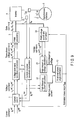
- FIG. 1 is a block diagram showing a configuration of a sensorless control apparatus according to the first embodiment
- FIG. 2 shows definitions of coordinate systems relating to vector control
- FIG. 3 shows gate commands and voltage commands generated by PWM processing
- FIG. 4 shows voltage vectors corresponding to gate commands on the a-b coordinate system
- FIG. 5 shows frequency components of a PWM voltage command
- FIG. 6 is a block diagram showing an example configuration of a high-frequency voltage calculator 8 ;
- FIG. 7 is a block diagram showing an example configuration of a high-frequency voltage calculator 7 ;
- FIG. 8 is a block diagram showing a high-frequency component selector 18 ;
- FIG. 9 is a block diagram showing a configuration of a sensorless control apparatus according to the second embodiment.
- FIG. 10 is a block diagram of an angle-of-rotation estimation calculation PLL
- FIG. 11 is a block diagram showing a configuration of a rotational phase angle estimator 13 ;
- FIG. 12 shows an example circuit configuration of a circuit which calculates an estimated phase angle, based on a characterizing amount R and an offset amount;
- FIG. 13 is a block diagram showing a configuration of a sensorless control apparatus according to the fourth embodiment.
- FIG. 14 is a vector diagram showing operation of the fourth embodiment
- FIG. 15 plots components of a high-frequency voltage
- FIG. 16 plots components of a high-frequency voltage
- FIG. 17 is a waveform diagram showing a high-frequency voltage command.
- FIG. 18 defines a phase angle of a high-frequency voltage command.
- a sensorless control apparatus for a synchronous motor comprising: a PWM processing unit which pulse-width-modulates a three-phase voltage command, based on comparison between the three-phase voltage command and a PWM carrier, and thereby generates a gate command for an inverter; a high-frequency voltage calculator which obtains a high-frequency voltage component by calculating at least one of sine components and cosine components of a plurality of frequencies not lower than a carrier frequency of the PWM carrier, the components included in an output of the PWM processing unit or an equivalent output value; a high-frequency current calculator which obtains a high-frequency current component by calculating at least one of sine components and cosine components having a plurality of frequencies not lower than the carrier frequency, the components being included in a current response value from a synchronous motor driven by the inverter; and an estimated angle calculator which calculates an estimated phase angle indicative of an estimated value of an angle of rotation of the synchronous motor, based on a plurality of
- FIG. 1 is a block diagram showing a configuration of the first embodiment of the sensorless control apparatus.
- An inverter 4 comprises a known three-phase switching circuit.
- the inverter 4 converts a direct current voltage into a three-phase alternating-current voltage which has a desired size and a desired frequency by turning on/off each switching element upon receipt of a gate command, and drives a synchronous motor 5 .
- a PWM processing unit 3 generates an on/off gate command to each switching element of in the inverter 4 by comparing a three-phase voltage command and an internally generated triangle carrier, as in a common triangle-wave comparison PWM method.
- Other available PWM processing methods are hysteresis PWM and spatial vector PWM.
- hysteresis PWM a three-phase current command is used as an input.
- an on/off gate command for each switching element is generated.
- the spatial vector PWM is input with a three-phase voltage command, and generates an on/off gate command to each switching element by calculating a voltage vector and an output time thereof to be output from the inverter, depending on spatial position where the voltage command is considered as a vector.
- a current controller 1 performs calculation to control rotation of an electric motor 5 .
- the current controller 1 is input with current commands I ⁇ ref and I ⁇ ref and current responses I ⁇ res and I ⁇ res , and outputs voltage commands V ⁇ ref and V ⁇ ref .
- a different method may alternatively be adopted.
- a rotational speed command can be input.
- a control method called vector control is generally employed at present. The present embodiment also employs this control method.
- a direction of magnetic flux of the permanent magnet is defined as an axis d while an axis perpendicular to axis d is defined as axis q.
- a U-phase winding direction is defined as an axis a
- a direction perpendicular to the U-phase winding direction is defined as an axis b.
- An angle to a d-axis direction from the a-axis direction as a reference is defined as a rotational phase angle ⁇ of the synchronous motor.
- V d , V q d-axis voltage, q-axis voltage
- I d , I q d-axis current, q-axis current
- the present control apparatus does not comprise an angle-of-rotation sensor for an electric rotor (rotator), and therefore cannot detect the angle of rotation ⁇ directly. Accordingly, a phase angle estimated by the control apparatus is used instead. Accordingly, as shown in FIG. 2 , the estimated phase angle is defined as ⁇ est , and a corresponding coordinate system is defined as axes ⁇ and ⁇ . When an estimated error ⁇ occurs, an axes ⁇ and ⁇ are positioned, rotated by ⁇ from the axes d and q.
- a current command is supplied from an upper control system.
- a ⁇ -axis current command I ⁇ ref and a ⁇ -axis current command I ⁇ ref are expressed by Expression 2 below.
- I ⁇ ref Trq ref ⁇ k ⁇ cos( ⁇ i )
- I ⁇ ref Trq ref ⁇ k ⁇ sin( ⁇ i )
- Trq ref torque command
- ⁇ i current phase angle with reference to axis ⁇ on the ⁇ - ⁇ coordinate system ( FIG. 2 ).
- ⁇ i may be a preset constant value or may be varied in accordance with torque.
- ⁇ i is mostly stored in a table or in a function in order that maximum torque can be obtained at the smallest current amplitude.
- Current commands I ⁇ ref and I ⁇ ref can be provided by preparing a lookup table which can be configured by using a ROM with a torque command as a parameter and by referring to this table.
- the current controller 1 is input with current commands I ⁇ ref and I ⁇ ref obtained as described above and a ⁇ -axis response values I ⁇ res and a ⁇ -axis response value I ⁇ res of a current flowing through the synchronous motor, and calculates a ⁇ -axis voltage command V ⁇ ref and a ⁇ -axis voltage command V ⁇ ref by proportional-plus-integral control as follows.
- K p proportional gain
- K i integral gain
- s Laplace operator
- a voltage-command coordinate converter 2 performs coordinate conversion on the ⁇ -axis voltage command V ⁇ ref and ⁇ -axis voltage command V ⁇ ref by calculation as follows, based on the estimated rotational phase angle (estimated phase angle) ⁇ est to obtain three-phase voltage commands V u ref , V v ref , and V w ref .
- the three-phase voltage commands obtained by the foregoing Expression 4 are input to the PWM processing unit 3 .
- the current-response coordinate converter 6 obtains a ⁇ -axis current response value I ⁇ res and a ⁇ -axis current response value I ⁇ res , by performing coordinate conversion on current values I U res , I V res , and I W res detected by the current sensor of the synchronous machine 5 , by calculation as expressed by Expression 5 below, based on the estimated phase angle ⁇ est output from the rotational phase angle estimation unit 9 .
- the ⁇ -axis current response value I ⁇ res and ⁇ -axis current response value I ⁇ res can be obtained from current values I U res and I W res of two phases among the three-phase currents as expressed by a next expression.
- the current detectors 20 need only to be provided for two phases, and the apparatus can be simplified more than when three-phase currents are detected.
- the current response values I u res , I v res , and I v res are generally output as analogue voltage values by a hole CT and a shunt resistance as current detection means, are converted into digital values by an analogue/digital converter, and are used for calculation by the control apparatus.
- FIG. 3 shows a gate command (b) generated by a PWM processing (a), and an ab-axis voltage command (c) for a fixed coil.
- the PWM processing unit 3 converts the three-phase voltage commands calculated as expressed by the Expression 4 into the gate commands to the inverter 4 .
- voltage commands V u ref , V v ref , and V w ref are compared with a triangle wave carrier by the PWM processing unit 3 , and gate commands G u , G v , and G w are thereby generated as comparative results.
- FIG. 3 graphically shows gate commands for a switching element of an upper arm (a switching circuit connected to a positive direct-current power supply) of the inverter 4 .
- Gate commands for a switching element of an upper arm (a switching circuit connected to a positive direct-current power supply) of the inverter 4 are logical inversion of the gate commands for the upper arm.
- the upper- and lower-arm gate commands are provided with upper- and lower-arm-shortcircuit prevention periods (dead time) to prevent malfunctions of elements.
- both gate commands are turned off for a predetermined period. In the present embodiment, the dead time is considered small enough to be negligible and is therefore omitted.
- FIG. 4 shows voltage vectors corresponding to gate commands on the ab-axis coordinate system.
- voltage vectors corresponding to the gate commands may be converted into values viewed from the axes a and b, as shown FIG. 4 .
- FIG. 4 shows a case of normalizing lengths (values) of voltage vectors V 1 to V 6 to 1, these values may be actual voltage values corresponding to inverter direct-current voltages.
- bracketed numerals 0 and 1 appended to each of voltage vectors express gate commands and are arranged in the order of Gu, Gv, and Gw ((b) of FIG. 3 ). Where these numerals are regarded as binary numerals of sequential bits and converted into decimal numbers, vector counts 0 to 7 are obtained. However, correspondence between the vector counts and the gate commands is not always set as exactly described above insofar as correspondence between the gate commands and the ab-axis voltage values needs only to be satisfied.
- voltage vector V 1 corresponds to (001) where expressed as a gate command concerning u, v, and w.
- V 2 to V 7 and V 0 are (010), (011), (100), (101), (110), (111), and (000).
- V 0 and V 7 have a uvw correlative voltage of zero and are therefore referred to as zero-voltage vectors.
- voltage vectors V 1 to V 6 are referred to as non-zero-voltage vectors.
- voltage vectors V 7 , V 6 , V 4 , and V 0 are output respectively during periods T 1 , T 2 , T 3 , T 4 , . . . .
- uvw gate commands can be converted into ab-axis voltage commands Va ref and Vb ref in the same manner as described above.
- the coordinate conversion as described above can be alternatively achieved by using, for example, a lookup table (described later) which is input with G u , G v , and G w and outputs corresponding Va ref and Vb ref in a high-frequency voltage calculator 8 .
- a lookup table (described later) which is input with G u , G v , and G w and outputs corresponding Va ref and Vb ref in a high-frequency voltage calculator 8 .
- Such voltage commands Va ref and Vb ref after pulse-width modulation are configured by time-based combinations of six non-zero-voltage vectors, which the inverter can output instantaneously, and two zero-voltage vectors, and include high-frequency components not lower than a carrier frequency.
- high-frequency components not lower than a carrier frequency but included in a voltage command i.e., high-frequency components are extracted and graphically expressed as shown in FIG. 5 .
- FIG. 5 shows a result of subjecting only the a-axis direction voltage command Va ref as a target to Fourier series expansion by a carrier cycle, calculating up to fifth-order sine and cosine components of the carrier frequency, and the components layered on a pulse waveform of V a ref .
- a signal “SUM” is a sum of components up to the tenth order. The “SUM” approximates further to V a ref if addition is performed up to higher orders.
- the voltage command V a ref has the same cycle as a triangle carrier cycle. Accordingly, the voltage command after pulse-width modulation is found to include high-frequency components not lower than the carrier frequency. This can be expressed as Expression 7 by use of Fourier series expansion.
- FIG. 6 is a block diagram showing an example configuration of the high-frequency voltage calculator 8 .
- the high-frequency voltage calculator 8 generates Fourier series (high-frequency voltage components) V axn , V ayn , V bxn , and V byn by the configuration shown in FIG. 6 based on Expression 8.
- the “high-frequency voltage” means a sufficiently higher frequency than a rotational frequency of the electric motor in a wide sense in the field of sensorless control.
- Fourier series expansion at a frequency not lower than a carrier frequency is calculated.
- the carrier frequency is sufficiently higher than the rotational frequency and can be said to be a high frequency.
- only voltage values used for the Fourier series expansion are used for phase angle estimation. Therefore, the Fourier series at the time of performing the Fourier series expansion can be regarded as high-frequency voltage components.
- a gate-signal/voltage-conversion table 11 is a lookup table which is input with gate commands Gu, Gv, and Gw from the PWM processing unit 3 , outputs corresponding ab-axis voltage commands Va ref and Vb ref , and is configured by a ROM.
- a Fourier series expander 12 expands a voltage command Va ref by Fourier series expansion, and outputs Fourier series (high-frequency voltage components) V axn and V ayn .
- a Fourier series expander 13 expands a voltage command Vb ref by Fourier series expansion, and outputs Fourier series (high-frequency voltage components) V bxn and V byn .
- ab-axis voltage commands after pulse-width modulation each can be expressed as a sum of sin and cosine components at a plurality of frequencies.
- individuals of sine and cosine components each have no other frequency component.
- sine and cosine components at equal frequencies are independent from each other, i.e., do not include components of each other.
- the foregoing high-frequency voltage calculator 8 directly samples gate commands as output from the PWM processing unit 3 , and extracts high-frequency components.
- the high-frequency voltage calculator 8 may be configured as a system which simulates the PWM processing and separately calculates values equivalent to outputs of the PWM processing unit 3 , based on a signal from a preceding stage of the PWM processing unit 3 , for example, three-phase voltage commands.
- high-frequency components as described above are used for angle-of-rotation estimation.
- a voltage equation model of Expression 1 is expressed as Expression 9 where the model is expressed on a static coordinate system.
- an inductance matrix L 00 to L 11 is expressed by Expression 11 below from Expression 9.
- inductance matrices L 00 to L 11 are calculated from a voltage and high-frequency components of a current on the basis on Expression 10, high-frequency components of current derivative terms are required.
- High-frequency components of current derivative terms can be expressed as Expression 12 by using Fourier series expansion, like Expression 7 concerning voltages.
- Respective coefficient terms on the right side of Expression 12 above are Fourier series, and can be expressed as Expression 13 below like Expression 8.
- ⁇ i . axn 2 ⁇ f c ⁇ ⁇ - tc tc ⁇ I .
- ayn 2 ⁇ f c ⁇ ⁇ - tc tc ⁇ I .
- bxn 2 ⁇ f c ⁇ ⁇ - tc tc ⁇ I .
- FIG. 7 is a block diagram showing an example configuration of the high-frequency voltage calculator 7 .
- the high-frequency voltage calculator 7 generates Fourier series (high-frequency voltage components of current derivative terms) i ⁇ axn , i ⁇ ayn , i ⁇ bxn , and i ⁇ byn by a configuration as shown in FIG. 7 based on Expressions 12 and 13.
- a three-phase/ab-axis coordinate converter is input with three-phase-current response values Iu and Iw from a current detector 20 , and outputs corresponding ab-axis response values Ia and Ib.
- a differential value calculator 15 calculates differential values I ⁇ a and I ⁇ b of the current response values Ia and Ib.
- a Fourier series expander 16 expands a differential value I ⁇ a by Fourier series expansion, and outputs Fourier series (high-frequency voltage components of a current derivative value) i ⁇ axn and i ⁇ ayn .
- a Fourier series expander 17 expands a differential value I ⁇ b by Fourier series expansion, and outputs Fourier series (high-frequency voltage components of a current derivative value) i ⁇ bxn and i ⁇ byn .
- the high-frequency components v xn , v yn , i ⁇ xn , and i ⁇ yn each are independent in view of frequencies, sine, and cosine. Therefore, if sine and cosine components at an equal frequency are extracted from a voltage and a current with respect to the axes a and b, the components can be reconstructed in form of a matrix as expressed by Expression 14 below.
- FIG. 8 shows a high-frequency component selector 18 which performs such vector selection.
- the high-frequency component selector 18 is a member comprised in the rotational phase angle estimator 9 .
- s and t are respectively integers different from each other and ranging from 1 to maximum order m, which have been subjected to Fourier series expansion.
- the rotational phase angle estimator 9 can calculate the inductance matrix L 00 to L 11 as expressed by Expression 16 below by matrix calculation as expressed by the foregoing Expression 15.
- transposition is performed by multiplying Expression 15 by an inverse matrix of an inductance matrix in order from the left side. Then, the inductance matrix L 00 to L 11 is calculated by using an inverse matrix of a transposed matrix of a voltage matrix.
- the rotational phase angle estimator 9 can obtain the angle of rotation ⁇ est as expressed by Expression 17 using Expression 11.
- the rotational phase angle estimator 9 estimates the angle of rotation ⁇ est by using the voltage command value after pulse-width modulation and high-frequency components of a current response value.
- two vectors are extracted from a voltage and high-frequency components of a current derivative value.
- three or more high-frequency component vectors may be used.
- the inductance matrix is calculated from Expression 14, and an inverse matrix cannot be calculated. Therefore, an approximate solution of the inductance matrix is obtained by using a pseudo-inverse matrix.
- the calculation using three or more vectors can perform calculation from more information than using only two vectors. Therefore, there is an effect in that calculation accuracy increases.
- Expression 12 requires calculation of current derivative terms.
- the current derivate terms can be expressed as differences between sampling values, and require no particular processing. Such differences are expressed as I ⁇ a and I ⁇ b, and Fourier series expansion as expressed by Expression 12 is performed to obtain current derivate terms as expressed by Expression 13.
- a noise component having a much higher frequency than the carrier frequency appears only in high-order components of Expression 12. Unless such high-order components are used for angle-of-rotation estimation calculation, noise components are isolated by frequencies and calculated. Therefore, calculation accuracy can be improved.
- noise components may be cut off by applying, to a current detection value, a high-pass filter which cuts off high-order components.
- a cutoff frequency may be set so as to allow a frequency band required for the angle-of-rotation estimation calculation to pass.
- the sensorless control apparatus can estimate the phase angle of the rotator without using a rotational phase angle sensor, and accordingly achieve size reduction, cost reduction, and easy maintenance. Further, the rotational phase angle is estimated aiming for voltage commands after pulse-width modulation and high-frequency components of a current response value. In this manner, the rotational phase angle can be estimated accurately without superimposing a high-frequency voltage, and there is a further effect that sampling management for current detection can be facilitated.
- FIG. 9 is a block diagram showing a configuration of the second embodiment. Components different from the first embodiment will now be described. The same components as those in the first embodiment will be respectively denoted at the same reference signs as those in the first embodiment, and detailed descriptions will be omitted.
- a PWM-voltage coordinate converter 20 converts gate commands G u , G v , G w after pulse-width modulation into voltage commands, and further converts the voltage commands into V ⁇ ref2 and V ⁇ ref2 on a ⁇ -coordinate system wherein an estimated phase angle ⁇ est is an angle of rotation.
- the conversion expression thereof is Expression 18 below, which has the same order as Expression 5.
- a high-frequency voltage calculator 21 frequency-resolves (by Fourier series expansion) the voltage commands V ⁇ ref2 and V ⁇ ref2 converted by the PWM-voltage coordinate converter 20 , as by Expression 19 similar to Expression 7, and outputs high-frequency components.
- a high-frequency current calculator 22 frequency-resolves (by Fourier series expansion) derivative terms from the current response values I ⁇ res and I ⁇ res converted into the ⁇ -coordinate system by Expression 20 similar to Expression 12, and outputs high-frequency components.
- a rotational phase angle estimator 13 estimates the rotational phase angle from the high-frequency voltage components and the high-frequency current components described above by calculation below. At first, from a voltage equation of a synchronous machine on the ⁇ -coordinate system, terms relating to high-frequency components are extracted to obtain Expression 21 below from consideration as Expression 10.
- a rotational phase angle estimator 13 calculates inductances as expressed by Expression 23 below, and can thereby obtain an angle-of-rotation estimation error ⁇ as expressed by Expression 24, based on high-frequency components of V ⁇ ref2 , V ⁇ ref2 , I ⁇ res , and I ⁇ res having frequencies, sine components, and cosine components corresponding to each other.
- L′ 01 can therefore be regarded as an estimated angle-of-rotation error ⁇ .
- the error can be obtained from L′ 10 . If an average between L′ 01 and L′ 10 is calculated, influence from individual calculation errors can be reduced.
- FIG. 10 is a block diagram of such a PLL, and the PLL is a component comprised in a high-frequency component selector 9 .
- the angle-of-rotation estimation error ⁇ is amplified by a PLL proportional gain Kp at an amplifier 31 , and is then input to an adder 34 .
- the angle-of-rotation estimation error ⁇ is amplified by a PLL proportional gain Kp at an amplifier 32 , is integrated by an integrator 33 , and is then input to an adder 34 .
- Output values from the amplifier 31 and integrator 33 are added up by the adder 34 , and a result thereof is input as an estimated angle-of-rotation speed ⁇ to the integrator 35 .
- the integrator 35 integrates the angle speed ⁇ , and outputs the estimated phase angle ⁇ est .
- the estimated output-phase angle ⁇ est varies in accordance with the value of the estimated angle-of-rotation error ⁇ . However, when the estimated error ⁇ is zero, the estimated output-phase angle ⁇ est does not vary.
- FIG. 11 shows an example configuration to practice this method.
- the estimated phase angle ⁇ est is obtained by adding ⁇ to a previous calculation value (Z ⁇ 1 ).
- a processing such as a PLL is not required, and there is an effect that calculation is simplified.
- a parameter such as L 1 includes an error depending on temperature change and a phenomenon of magnetic flux saturation. Therefore, obtained ⁇ also includes an error.
- a high-frequency voltage value and a high-frequency current value also include detection errors and calculation errors.
- ⁇ basically includes an error. Since such an error varies each time control calculation is performed, the error directly influences even an estimated phase angle which is directly obtained at a relatively high frequency. On the other side, if a PLL is used as shown in FIG. 10 , calculation which obtains an estimated phase angle from ⁇ can have a function of low-pass filter. Therefore, influence of an error at a high frequency, which is included in the estimated error ⁇ as described above, can be prevented from appearing in the estimated phase angle.
- the sensorless control apparatus can estimate the phase angle of the rotator without using a rotational phase angle sensor, and can therefore achieve size reduction, cost reduction, and easy maintenance. Further, the rotational phase angle is estimated aiming for a voltage command after pulse-width modulation and a high-frequency component of a current response value. In this manner, the rotational phase angle can be estimated accurately without superimposing a high-frequency voltage. Also according to the present embodiment, an effect is obtained in that sampling management in current detection can be facilitated. Besides, calculation can be simplified and influence of errors can be reduced.
- a high-frequency voltage value and a high-frequency current value are obtained from a voltage command value and a current response value after pulse-width modulation.
- the present embodiment employs the same calculation as the first and second embodiments up to obtaining of an inductance matrix but employs different calculation after obtaining the inductance matrix up to the obtaining of an estimated phase angle. That is, the internal configuration of each rotational phase angle estimator differs. Therefore, a block diagram showing the configuration of the present embodiment will be omitted.
- an estimated angle-of-rotation error can be converted into zero by inputting R in place of ⁇ by using the PLL shown in FIG. 10 .
- the characterizing amount R has a proportional relationship with an offset to ⁇ in some cases. In this case, an offset amount may be measured/set in advance and then be subtracted.
- FIG. 12 shows an example circuit configuration of calculating an estimated phase angle ⁇ est, based on the characterizing amount R and offset amount. The circuit is comprised in the rotational phase angle estimator. According to this circuit configuration, in front of the PLL expressed in FIG. 10 , there is added a subtractor 40 which subtracts an offset amount R 0 for the characterizing amount from the characterizing amount R expressed by Expression 26. There is a case where the offset amount R 0 varies under conditions about torque and a current. In this case, for example, a parameter table may be provided and set in advance, and may be referred to, depending on operating conditions.
- the sensorless control apparatus can estimate the phase angle of the rotator without using a rotational phase angle sensor, and can achieve size reduction, cost reduction, and easy maintenance. Further, the rotational phase angle is estimated aiming for a voltage command after pulse-width modulation and a high-frequency component of a current response value. In this manner, the rotational phase angle can be estimated accurately without superimposing a high-frequency voltage. Further, the present embodiment can cope with even a state that magnetic flux saturation occurs during high load and causes inductances to vary.
- FIG. 13 is a block diagram showing a configuration of the fourth embodiment.
- the present embodiment can be added to the first or second embodiment.
- the voltage command determination unit 41 regards voltage commands V ⁇ ref and V ⁇ ref for controlling an electric motor as a voltage command vector V ref , and determines whether the direction of the voltage command vector V ref is in the vicinity of the direction of a non-zero-voltage vector of an inverter or not.
- the voltage-command determination unit 41 is a component which can be suitably added to the first or second embodiment. If the direction is determined to be in the vicinity, the voltage-command determination unit 41 superimposes, on the voltage command vector, a high-frequency voltage Vhf in a direction perpendicular to the voltage command vector, in order that the direction shifts away from the vicinity. The high-frequency voltage V hf is superimposed for a reason described later.
- FIG. 14 is a vector diagram showing operation of the present embodiment.
- an output-voltage command vector V ref configured by (V ⁇ ref , V ⁇ ref ) is calculated with respect to an axes ⁇ and ⁇ at an angle of an estimated phase angle ⁇ est .
- supposing that a phase angle of V ref from axis ⁇ is ⁇ v, whether V ref is in the vicinity of a non-zero-voltage vector of the inverter or not can be determined by Expression 27 below.
- V ⁇ ⁇ ⁇ hf V hf ⁇ sin ⁇ ( 2 ⁇ ⁇ ⁇ ⁇ ⁇ f hf ⁇ ⁇ t ) ⁇ cos ⁇ ( ⁇ v + ⁇ 2 )
- V ⁇ ⁇ ⁇ hf V hf ⁇ sin ⁇ ( 2 ⁇ ⁇ ⁇ ⁇ ⁇ f hf ⁇ ⁇ t ) ⁇ sin ⁇ ( ⁇ v + ⁇ 2 )
- V hf is a high-frequency voltage amplitude and is a parameter to be set to a predetermined value in advance.
- f hf is a high frequency and is set to a frequency not lower than a carrier frequency.
- the high-frequency voltage V ⁇ hf and V ⁇ hf are added to voltage commands V ⁇ ref and V ⁇ ref by an adder 42 , and are supplied to a voltage-command coordinate converter 2 .
- a voltage and a current are decomposed into frequency components, sine components, and cosine components.
- a matrix is configured thereby to directly calculate an inductance matrix or an estimated phase angle through matrix calculation.
- the calculation cannot be completed in some cases. That is, there is a case where no inverse matrix of high-frequency components exists in Expressions 16 and 23.
- Presence of an inverse matrix can be determined by whether a matrix expression is zero or not, and more intuitively by whether a column vectors forming the matrix have components spatially perpendicular to each other or not. That is, in Expression 16, if vectors [V aks V bks ] T and [V alt V blt ] T satisfy a relationship of linear independence, an inverse matrix exists (where suffix T denotes a transposed vector).
- These voltage vectors are sine or cosine components at a specific frequency, which are included in voltage command values after pulse-width modulation, the command values being calculated by Expression 8. Therefore, whether the condition described above is satisfied or not can be estimated in advance. That is, if none of all the high-frequency voltage components calculated by Expression 8 are linearly independent or, in other words, if all the high-frequency voltage components satisfy the relationship of linear dependence, the direction of the output-voltage command vector before pulse-width modulation matches any of six non-zero-voltage vectors of the inverter.
- FIG. 15 shows an example in which V a ref and V b ref shown in (c) of FIG. 3 are decomposed into high-frequency components, and plotted as vectors.
- vectors from an origin to points A and B are respectively expressed as [v a1 v b1 ] T and [v a2 v b2 ] T
- vectors to other points have components in directions perpendicular to vectors [v a1 v b1 ] T and [v a2 v b2 ] T .
- Vector [v a1 v b1 ] T denoted at point A is a second-order cosine component, corresponding to a waveform A shown in FIG. 5 .
- Vector [v a2 v b2 ] T is a third-order cosine component, corresponding to a waveform B in FIG.
- vector [v a1 v b1 ] T also expresses a component having the greatest amplitude (absolute value) among high-frequency components obtained by performing Fourier series expansion on V a ref and V b ref .
- Vector [v a2 v b2 ] T also expresses a component having the second greatest amplitude (absolute value) among the high-frequency components.
- FIG. 16 shows an example of plotting high-frequency components of voltage commands for which directions of output-voltage command vectors V ⁇ ref and V ⁇ ref before pulse-width modulation match non-zero-voltage vectors of the inverter.
- FIG. 16 shows a case where the output-voltage command vector is in the direction of V 6 .
- all high-frequency components found to be in one line and satisfy the relationship of linear dependence. In this case, the calculation of neither Expression 16 nor 23 exists, and accordingly, angle-of-rotation estimation is impossible.
- the present embodiment arranges the output voltage command vectors so as not to match the non-zero-voltage vectors, by superimposing a high-frequency voltage on directions perpendicular to the output voltage command vectors V ⁇ ref and V ⁇ ref . Accordingly, a high-frequency voltage vector used for angle-of-rotation estimation calculation can securely satisfy the relationship of linear independence, and angle-of-rotation estimation can be securely performed.
- V ⁇ ⁇ ⁇ hf V hf ⁇ sin ⁇ ( 2 ⁇ ⁇ ⁇ ⁇ ⁇ f hf ⁇ t ) ⁇ cos ⁇ ( ⁇ vhf - ⁇ est )
- V ⁇ ⁇ ⁇ hf V hf ⁇ sin ⁇ ( 2 ⁇ ⁇ ⁇ ⁇ ⁇ f hf ⁇ t ) ⁇ sin ⁇ ( ⁇ vhf - ⁇ est )
- FIG. 17 shows examples of waveforms of such alternating high-frequencies.
- FIG. 18 shows a definition of a phase of Expression 29.
- ⁇ vhf takes a value other than 0°, 60°, 120°, 180°, 240°, and 300° and desirably an intermediate value therebetween, for example, 30°, 90°, 150°, 210°, 270°, or 330°. These angles correspond to intermediate directions of the directions of the non-zero-voltage vectors, and are therefore effective in that high-frequency voltage components having the relationship of linear independence can be easily obtained.
- the present embodiment uses an alternating high-frequency in a predetermined direction shown in FIGS. 17 and 18 , as a high-frequency voltage to be superimposed on the voltage commands V ⁇ ref and V ⁇ ref by the voltage command determination unit 41 .
- the high-frequency voltage to be superimposed may be of any form, for example, a rotational high-frequency, insofar as the effects as described above are obtained (for example, to obtain high-frequency voltage components having the relationship of linear independence).
- the frequency of the high-frequency voltage needs to be at least equal to or lower than a carrier frequency since superimposed output voltage commands are subjected to pulse-width modulation by the pulse-width modulator 3 . This is because a high-frequency higher than a carrier frequency is not correctly reflected on an output voltage from the principle of PWM.
- a lower limit to the frequency may be set to be as sufficiently high as tolerable torque pulsation since a high-frequency current which flows because of the high-frequency voltage can become torque pulsation.
- the carrier frequency is far higher than a torque pulsation frequency which is mechanically tolerable. Therefore, a frequency band of the high-frequency voltage can be sufficiently wide.
- the high-frequency voltage is expressed as a sine wave in Expressions 28 and 29, a rectangular-wave alternating voltage may alternatively be used for simplification. In this manner, control calculation can be simplified.
- conditions for high-frequency voltage components for performing angle-of-rotation estimation may be directly used as conditions for high-frequency current components if only the calculation method is changed. That is, although matrix calculation is performed to estimate an angle of rotation from Expression 15, an inductance matrix can be calculated even in a method of calculating an inverse matrix of a current in place of an inverse matrix of a voltage. In this case, the conditions for the voltage need to be directly applied as conditions for the current. Further in this case, a high-frequency voltage to be superimposed to complete calculation can be substituted with high-frequency current command values. In a case of superimposing the high-frequency current command values, current command values input to the current controller may be added with the high-frequency current command values.
- the high-frequency component vectors of the voltage and current have as great absolute values as possible.
- a component having the greatest absolute value is adopted as a point A
- a component having the second greatest absolute value is adopted as a point B, among calculated high-frequency voltage components.
- further another method for improving calculation accuracy is to make selection so as to increase an exterior product of two vectors [v a1 , v b1 ] T and [v a2 , v b2 ] T which form a voltage matrix.
- a denominator of a coefficient term of Expression 16 increases, and calculation can be completed with high accuracy.
- Such a selection processing for selecting vectors (high-frequency components) is carried out by a high-frequency component selector 18 shown in FIG. 8 .
- the high-frequency component selector 18 firstly searches for and selects a vector having the greatest absolute value.
- the selector 18 selects another vector which produces the greatest exterior product with the selected vector.
- another vector having the greatest component is selected in a direction perpendicular to the selected greatest vector.
- a vector having the greatest absolute value i.e., a vector [v a1 , v b1 ] T is selected.
- another vector is selected which has the greatest component in a direction C perpendicular to vector [v a1 , v b1 ] T .
- both of this vector and the vector having the second greatest absolute value are [v a2 , v b2 ] T and thus match each other.
- an inductance matrix is desirably calculated by selecting combinations of the greatest vector and all the other vectors are selected and by searching for a pair which maximizes the exterior product.
- the sensorless control apparatus can estimate the phase angle of the rotator without using a rotational phase angle sensor, and can therefore achieve size reduction, cost reduction, and easy maintenance. Further, the rotational phase angle is estimated aiming for voltage commands after pulse-width modulation and high-frequency components of a current response value. In this manner, the rotational phase angle can be estimated accurately by superimposing a minimum frequency voltage.
Landscapes
- Engineering & Computer Science (AREA)
- Power Engineering (AREA)
- Control Of Ac Motors In General (AREA)
- Control Of Motors That Do Not Use Commutators (AREA)
Abstract
Description
I γ ref=Trqref ·k·cos(θi)
I δ ref=Trqref ·k·sin(θi)
where fc is a carrier frequency, n is an integer not smaller than 1, and Vaxn, Vayn, Vbxn, and Vbyn are Fourier series and expressed by
where tc is time of a carrier half cycle. Fourier series of
where a subscript hf denotes a high-frequency component, and “·” denotes differentiation.
where a inductance matrix L′00 to L′11 is expressed by
R=L′ 00 +L′ 11=2L 0∝Δθ Expression 26
where L′00 and L′11 are inductances which are calculated based on high-frequency components of voltage command values Vγ ref2 and Vδ ref2 and current response values Iγ res and Iδ res, as expressed in
θVinv−Δθd≦θv+θest≦θVinv+Δθd Expression 27
where θVinv=0°, 60°, 120°, 180°, 240°, or 300° and Δθd is a constant for determining what range of orders to be regarded as the vicinity.
Claims (12)
Applications Claiming Priority (4)
| Application Number | Priority Date | Filing Date | Title |
|---|---|---|---|
| JP2011186126 | 2011-08-29 | ||
| JP2011-186126 | 2011-08-29 | ||
| JP2012127546 | 2012-06-04 | ||
| JP2012-127546 | 2012-06-04 |
Publications (2)
| Publication Number | Publication Date |
|---|---|
| US20130049656A1 US20130049656A1 (en) | 2013-02-28 |
| US9450528B2 true US9450528B2 (en) | 2016-09-20 |
Family
ID=46924234
Family Applications (1)
| Application Number | Title | Priority Date | Filing Date |
|---|---|---|---|
| US13/596,550 Active 2034-05-28 US9450528B2 (en) | 2011-08-29 | 2012-08-28 | Sensorless control apparatus for synchronous motor and inverter apparatus |
Country Status (4)
| Country | Link |
|---|---|
| US (1) | US9450528B2 (en) |
| EP (1) | EP2566045B1 (en) |
| JP (1) | JP5971707B2 (en) |
| CN (1) | CN102969967B (en) |
Cited By (2)
| Publication number | Priority date | Publication date | Assignee | Title |
|---|---|---|---|---|
| US20230052807A1 (en) * | 2021-08-09 | 2023-02-16 | Santak Electronic (Shenzhen) Co., Ltd. | Three-phase inverter control system and three-phase inverter control method |
| US11757375B2 (en) | 2021-12-27 | 2023-09-12 | Industrial Technology Research Institute | DC-AC inverter system using state observer and control method thereof |
Families Citing this family (30)
| Publication number | Priority date | Publication date | Assignee | Title |
|---|---|---|---|---|
| EP2568596B1 (en) * | 2011-09-09 | 2019-11-13 | Siemens Aktiengesellschaft | Method and processing unit for determining the position of the rotor of a synchronous machine relative to the stator of the synchronous machine |
| JP2013183532A (en) * | 2012-03-01 | 2013-09-12 | Toshiba Corp | Motor control device and control method of the same |
| JP6056959B2 (en) * | 2013-03-28 | 2017-01-11 | アイシン・エィ・ダブリュ株式会社 | Rotating electrical machine control device |
| WO2014174597A1 (en) * | 2013-04-23 | 2014-10-30 | 三菱電機株式会社 | Control device for alternating current electric motor |
| JP6003924B2 (en) * | 2014-02-25 | 2016-10-05 | 株式会社安川電機 | Rotating electrical machine control device and rotating electrical machine control method |
| CN103840485B (en) * | 2014-02-28 | 2015-02-25 | 山东大学 | Global synchronization pulse width modulation system and method of distributed grid-connected inverter system |
| JP2016021800A (en) * | 2014-07-14 | 2016-02-04 | 株式会社リコー | POSITION ESTIMATION DEVICE, MOTOR DRIVE CONTROL DEVICE, AND POSITION ESTIMATION METHOD |
| EP3252941B1 (en) * | 2015-01-28 | 2021-06-30 | Kabushiki Kaisha Toshiba | Inverter control apparatus and motor driving system |
| KR20160104166A (en) * | 2015-02-25 | 2016-09-05 | 한국전자통신연구원 | Motor driving device, method for controling motor and calculation device for calculating angle information of mortor |
| JP2016201924A (en) * | 2015-04-10 | 2016-12-01 | ニデック シンガポール ピーティーイー リミテッド | Rotation position estimation method for motor, and control apparatus for motor |
| JP2016201923A (en) * | 2015-04-10 | 2016-12-01 | ニデック シンガポール ピーティーイー リミテッド | Rotation position estimation method for motor, and control apparatus for motor |
| DE102015211863B4 (en) * | 2015-06-25 | 2026-01-29 | Lenze Se | Method for determining current-dependent and/or angle-dependent parameters of an electrical machine and frequency converter |
| JP6254977B2 (en) | 2015-07-22 | 2017-12-27 | ファナック株式会社 | Current detection circuit not affected by noise |
| JP6241460B2 (en) * | 2015-08-25 | 2017-12-06 | 株式会社デンソー | Electric motor control device |
| JP6469316B2 (en) | 2016-04-28 | 2019-02-13 | 三菱電機株式会社 | Failure determination device and failure determination method for rotating machine control device |
| JP2017197137A (en) * | 2016-04-28 | 2017-11-02 | 株式会社ジェイテクト | Electric power steering device |
| TWI668953B (en) * | 2016-08-22 | 2019-08-11 | 日商東芝股份有限公司 | Inverter control device and drive system |
| JP6767213B2 (en) * | 2016-09-05 | 2020-10-14 | 東芝インフラシステムズ株式会社 | Inverter controller and motor drive system |
| TWI654827B (en) * | 2016-09-05 | 2019-03-21 | 日商東芝股份有限公司 | Converter control device and motor driving system |
| JP6487396B2 (en) | 2016-09-06 | 2019-03-20 | ファナック株式会社 | Current detection circuit not affected by noise |
| JP6588410B2 (en) * | 2016-09-28 | 2019-10-09 | 株式会社神戸製鋼所 | Electric motor drive |
| JP6551473B2 (en) * | 2017-08-07 | 2019-07-31 | 株式会社安川電機 | Control device and control method |
| US11486404B1 (en) * | 2017-10-30 | 2022-11-01 | Hkc-Us, Llc | Switch housing remote control |
| US12369243B1 (en) | 2017-10-30 | 2025-07-22 | Hkc-Us, Llc | Switch housing remote control |
| DE102017012027A1 (en) * | 2017-12-22 | 2019-06-27 | Sew-Eurodrive Gmbh & Co Kg | Method for the encoderless rotor position determination of a rotary field machine and device for the encoderless control of a three-phase motor |
| US11374513B2 (en) * | 2019-01-23 | 2022-06-28 | Allegro Microsystems, Llc | Motor control circuit with degauss filter |
| JP2020150590A (en) * | 2019-03-11 | 2020-09-17 | コニカミノルタ株式会社 | Motor control unit, method for estimating initial position of magnetic pole of rotor, and image forming apparatus |
| CN111817618B (en) * | 2020-06-17 | 2021-07-23 | 北京航空航天大学宁波创新研究院 | Commutation error compensation system and method for brushless motor without position sensor |
| CN117705176B (en) * | 2024-02-06 | 2024-05-14 | 赛诺威盛科技(北京)股份有限公司 | A rotation angle pulse correction method, device, equipment and storage medium |
| KR102916041B1 (en) * | 2024-03-15 | 2026-01-20 | 한양대학교 산학협력단 | Alternating current motor control device and method thereof |
Citations (21)
| Publication number | Priority date | Publication date | Assignee | Title |
|---|---|---|---|---|
| US4617636A (en) * | 1982-03-03 | 1986-10-14 | National Research Development Corporation | Protection of electrical power supply systems |
| JP3168967B2 (en) | 1997-09-12 | 2001-05-21 | トヨタ自動車株式会社 | Electric angle detecting device and method, and motor control device |
| JP2002291283A (en) | 2001-03-26 | 2002-10-04 | Yaskawa Electric Corp | Method and controller for estimating magnetic pole position of synchronous motor |
| US20020149335A1 (en) * | 2001-02-16 | 2002-10-17 | Honda Giken Kogyo Kabushiki Kaisha | Rotor angle detecting apparatus for DC brushless motors |
| JP2003153582A (en) | 2001-11-14 | 2003-05-23 | Meidensha Corp | Control method and controller of pm motor |
| JP2004096856A (en) | 2002-08-30 | 2004-03-25 | Yaskawa Electric Corp | Control device for synchronous motor |
| US20040070360A1 (en) * | 2002-10-10 | 2004-04-15 | Steven E. Schulz | Amplitude detection method and apparatus for high frequency impedance tracking sensorless algorithm |
| US20040120699A1 (en) * | 2002-12-20 | 2004-06-24 | Lin Jyh Chain | Pulse width modulation current adjustment apparatus |
| US20040232862A1 (en) * | 2001-08-06 | 2004-11-25 | Wogari Mengesha Mamo | Electric motor pole position sensing method, pole position sensing apparatus, and electric motor control apparatus using the same |
| US20060097686A1 (en) | 2004-10-27 | 2006-05-11 | Kabushiki Kaisha Toshiba | Control system for synchronous machine |
| JP2006185552A (en) | 2004-12-28 | 2006-07-13 | Orion Denki Kk | Disk erroneous insertion preventing mechanism and disk device with the same |
| JP2007056183A (en) | 2005-08-26 | 2007-03-08 | Fuji Xerox Co Ltd | Polyamic acid composition, polyimide endless belt, and image forming apparatus |
| JP2008017608A (en) | 2006-07-05 | 2008-01-24 | Toshiba Corp | Sensorless control device for synchronous machine |
| US20080111516A1 (en) * | 2006-11-13 | 2008-05-15 | Denso Corporation | Control system for rotary electric machine with salient structure |
| JP2008220096A (en) | 2007-03-06 | 2008-09-18 | Toshiba Corp | Sensorless control device for synchronous motor |
| US20090021195A1 (en) * | 2006-12-27 | 2009-01-22 | Sanyo Electric Co., Ltd. | Motor control device and motor drive system |
| JP2009153347A (en) | 2007-12-21 | 2009-07-09 | Toshiba Corp | Control device for synchronous motor |
| US20100207555A1 (en) * | 2009-01-21 | 2010-08-19 | Young Doo Yoon | Alternating-current motor control apparatus |
| JP2010213437A (en) | 2009-03-10 | 2010-09-24 | Nissan Motor Co Ltd | Controller for motor and method of estimating the state of the same |
| US20110050140A1 (en) * | 2009-08-28 | 2011-03-03 | Hitachi Industrial Equipment Systems Co., Ltd. | Driving system of permanent magnet synchronous motor |
| US20110304290A1 (en) * | 2009-03-25 | 2011-12-15 | Mitsubishi Electric Corporation | Control apparatus and control method for electric rotating machine |
Family Cites Families (2)
| Publication number | Priority date | Publication date | Assignee | Title |
|---|---|---|---|---|
| JP3968688B2 (en) * | 2000-11-28 | 2007-08-29 | 有限会社シー・アンド・エス国際研究所 | Vector control method and apparatus for AC motor |
| JP4542797B2 (en) * | 2004-02-23 | 2010-09-15 | 株式会社東芝 | Control device for synchronous machine |
-
2012
- 2012-08-20 JP JP2012181791A patent/JP5971707B2/en not_active Expired - Fee Related
- 2012-08-28 US US13/596,550 patent/US9450528B2/en active Active
- 2012-08-28 EP EP12181936.1A patent/EP2566045B1/en not_active Not-in-force
- 2012-08-29 CN CN201210384313.2A patent/CN102969967B/en active Active
Patent Citations (26)
| Publication number | Priority date | Publication date | Assignee | Title |
|---|---|---|---|---|
| US4617636A (en) * | 1982-03-03 | 1986-10-14 | National Research Development Corporation | Protection of electrical power supply systems |
| JP3168967B2 (en) | 1997-09-12 | 2001-05-21 | トヨタ自動車株式会社 | Electric angle detecting device and method, and motor control device |
| US20020149335A1 (en) * | 2001-02-16 | 2002-10-17 | Honda Giken Kogyo Kabushiki Kaisha | Rotor angle detecting apparatus for DC brushless motors |
| US20040113582A1 (en) | 2001-03-26 | 2004-06-17 | Kozo Ide | Method for estimating magnetic polar position of synchronous motor and its controller |
| JP2002291283A (en) | 2001-03-26 | 2002-10-04 | Yaskawa Electric Corp | Method and controller for estimating magnetic pole position of synchronous motor |
| US20040232862A1 (en) * | 2001-08-06 | 2004-11-25 | Wogari Mengesha Mamo | Electric motor pole position sensing method, pole position sensing apparatus, and electric motor control apparatus using the same |
| JP2003153582A (en) | 2001-11-14 | 2003-05-23 | Meidensha Corp | Control method and controller of pm motor |
| JP2004096856A (en) | 2002-08-30 | 2004-03-25 | Yaskawa Electric Corp | Control device for synchronous motor |
| US20070069682A1 (en) * | 2002-08-30 | 2007-03-29 | Kozo Ide | Control device for synchronous motor |
| US20040070360A1 (en) * | 2002-10-10 | 2004-04-15 | Steven E. Schulz | Amplitude detection method and apparatus for high frequency impedance tracking sensorless algorithm |
| US20040120699A1 (en) * | 2002-12-20 | 2004-06-24 | Lin Jyh Chain | Pulse width modulation current adjustment apparatus |
| US20060097686A1 (en) | 2004-10-27 | 2006-05-11 | Kabushiki Kaisha Toshiba | Control system for synchronous machine |
| CN1777017A (en) | 2004-10-27 | 2006-05-24 | 株式会社东芝 | Control system for synchronous machine |
| JP2006185552A (en) | 2004-12-28 | 2006-07-13 | Orion Denki Kk | Disk erroneous insertion preventing mechanism and disk device with the same |
| JP2007056183A (en) | 2005-08-26 | 2007-03-08 | Fuji Xerox Co Ltd | Polyamic acid composition, polyimide endless belt, and image forming apparatus |
| JP2008017608A (en) | 2006-07-05 | 2008-01-24 | Toshiba Corp | Sensorless control device for synchronous machine |
| US20080111516A1 (en) * | 2006-11-13 | 2008-05-15 | Denso Corporation | Control system for rotary electric machine with salient structure |
| US20090021195A1 (en) * | 2006-12-27 | 2009-01-22 | Sanyo Electric Co., Ltd. | Motor control device and motor drive system |
| JP2008220096A (en) | 2007-03-06 | 2008-09-18 | Toshiba Corp | Sensorless control device for synchronous motor |
| CN101542891A (en) | 2007-03-06 | 2009-09-23 | 株式会社东芝 | Sensorless control device for synchronous motor |
| US20090315495A1 (en) * | 2007-03-06 | 2009-12-24 | Kazuya Yasui | Sensorless control apparatus of synchronous motor |
| JP2009153347A (en) | 2007-12-21 | 2009-07-09 | Toshiba Corp | Control device for synchronous motor |
| US20100207555A1 (en) * | 2009-01-21 | 2010-08-19 | Young Doo Yoon | Alternating-current motor control apparatus |
| JP2010213437A (en) | 2009-03-10 | 2010-09-24 | Nissan Motor Co Ltd | Controller for motor and method of estimating the state of the same |
| US20110304290A1 (en) * | 2009-03-25 | 2011-12-15 | Mitsubishi Electric Corporation | Control apparatus and control method for electric rotating machine |
| US20110050140A1 (en) * | 2009-08-28 | 2011-03-03 | Hitachi Industrial Equipment Systems Co., Ltd. | Driving system of permanent magnet synchronous motor |
Non-Patent Citations (2)
| Title |
|---|
| Chinese Office Action dated Aug. 5, 2014, issued in counterpart application No. 2012103843132 and an English translation thereof. |
| Japanese Office Action (and English translation thereof) dated Dec. 22, 2015, issued in counterpart Japanese Application No. 2012-181791. |
Cited By (3)
| Publication number | Priority date | Publication date | Assignee | Title |
|---|---|---|---|---|
| US20230052807A1 (en) * | 2021-08-09 | 2023-02-16 | Santak Electronic (Shenzhen) Co., Ltd. | Three-phase inverter control system and three-phase inverter control method |
| US12047014B2 (en) * | 2021-08-09 | 2024-07-23 | Santak Electronic (Shenzhen) Co., Ltd. | Three-phase inverter control system and three-phase inverter control method |
| US11757375B2 (en) | 2021-12-27 | 2023-09-12 | Industrial Technology Research Institute | DC-AC inverter system using state observer and control method thereof |
Also Published As
| Publication number | Publication date |
|---|---|
| JP2014014252A (en) | 2014-01-23 |
| EP2566045B1 (en) | 2019-08-14 |
| EP2566045A2 (en) | 2013-03-06 |
| US20130049656A1 (en) | 2013-02-28 |
| CN102969967B (en) | 2015-04-15 |
| CN102969967A (en) | 2013-03-13 |
| JP5971707B2 (en) | 2016-08-17 |
| EP2566045A3 (en) | 2017-06-28 |
Similar Documents
| Publication | Publication Date | Title |
|---|---|---|
| US9450528B2 (en) | Sensorless control apparatus for synchronous motor and inverter apparatus | |
| US9124209B2 (en) | Method and apparatus for controlling power converter with inverter output filter | |
| US9294019B2 (en) | Method and apparatus for controlling power converter with inverter output filter | |
| KR102285041B1 (en) | Inverter control unit and motor drive system | |
| US20170264227A1 (en) | Inverter control device and motor drive system | |
| EP2424105A2 (en) | Vector control apparatus and motor control system | |
| EP1460758B1 (en) | Vector control method and apparatus | |
| WO2008004417A1 (en) | Sensorless control apparatus of synchronous machine | |
| KR102409792B1 (en) | Control device of permanent magnet synchronization electric motor, microcomputer, electric motor system, and driving method of permanent magnet synchronization electric motor | |
| TW201618450A (en) | Control device of AC rotary machine and method for calculating degree of correction of magnetic pole position | |
| JP5428202B2 (en) | Control device for permanent magnet type synchronous motor | |
| JP6374037B2 (en) | Motor control device | |
| CN113826314A (en) | Power conversion device and electric vehicle system including the same | |
| CN115004537A (en) | Motor drive device, outdoor unit of air conditioner using the same, and motor drive control method | |
| JP5238241B2 (en) | Control device for synchronous motor | |
| JP2007151344A (en) | Magnetic pole position estimation method, motor speed estimation method, and motor control apparatus | |
| WO2022009599A1 (en) | Motor control device and motor control method | |
| JP6541092B2 (en) | Control device of permanent magnet synchronous motor | |
| EP3474438B1 (en) | Motor control device and control method | |
| JP7251424B2 (en) | INVERTER DEVICE AND INVERTER DEVICE CONTROL METHOD | |
| JP2008086083A (en) | PWM inverter control device, PWM inverter control method, and refrigeration air conditioner | |
| JP6040689B2 (en) | AC motor control device | |
| JP5228435B2 (en) | Inverter control device and control method thereof | |
| JP2018125955A (en) | Motor control device | |
| JP7855139B2 (en) | Motor control device |
Legal Events
| Date | Code | Title | Description |
|---|---|---|---|
| AS | Assignment |
Owner name: KABUSHIKI KAISHA TOSHIBA, JAPAN Free format text: ASSIGNMENT OF ASSIGNORS INTEREST;ASSIGNOR:YASUI, KAZUYA;REEL/FRAME:028861/0005 Effective date: 20120820 |
|
| STCF | Information on status: patent grant |
Free format text: PATENTED CASE |
|
| MAFP | Maintenance fee payment |
Free format text: PAYMENT OF MAINTENANCE FEE, 4TH YEAR, LARGE ENTITY (ORIGINAL EVENT CODE: M1551); ENTITY STATUS OF PATENT OWNER: LARGE ENTITY Year of fee payment: 4 |
|
| MAFP | Maintenance fee payment |
Free format text: PAYMENT OF MAINTENANCE FEE, 8TH YEAR, LARGE ENTITY (ORIGINAL EVENT CODE: M1552); ENTITY STATUS OF PATENT OWNER: LARGE ENTITY Year of fee payment: 8 |