US9440313B2 - Hard drive data destroying device - Google Patents
Hard drive data destroying device Download PDFInfo
- Publication number
- US9440313B2 US9440313B2 US14/206,234 US201414206234A US9440313B2 US 9440313 B2 US9440313 B2 US 9440313B2 US 201414206234 A US201414206234 A US 201414206234A US 9440313 B2 US9440313 B2 US 9440313B2
- Authority
- US
- United States
- Prior art keywords
- electronic media
- storage device
- milling cutter
- hard drive
- media storage
- Prior art date
- Legal status (The legal status is an assumption and is not a legal conclusion. Google has not performed a legal analysis and makes no representation as to the accuracy of the status listed.)
- Active, expires
Links
- 238000003860 storage Methods 0.000 claims abstract description 59
- 238000013500 data storage Methods 0.000 claims abstract description 38
- 239000007787 solid Substances 0.000 claims abstract description 11
- 238000003801 milling Methods 0.000 claims description 75
- 238000005520 cutting process Methods 0.000 claims description 7
- 238000003754 machining Methods 0.000 claims 6
- 230000003287 optical effect Effects 0.000 claims 2
- 239000002245 particle Substances 0.000 claims 2
- 239000000126 substance Substances 0.000 abstract description 55
- 239000002904 solvent Substances 0.000 abstract description 18
- 230000006378 damage Effects 0.000 abstract description 6
- 238000000034 method Methods 0.000 description 18
- 230000008569 process Effects 0.000 description 14
- 239000011248 coating agent Substances 0.000 description 6
- 238000000576 coating method Methods 0.000 description 6
- 238000012795 verification Methods 0.000 description 6
- VEXZGXHMUGYJMC-UHFFFAOYSA-N Hydrochloric acid Chemical compound Cl VEXZGXHMUGYJMC-UHFFFAOYSA-N 0.000 description 4
- 238000000429 assembly Methods 0.000 description 4
- 238000010586 diagram Methods 0.000 description 4
- 239000004088 foaming agent Substances 0.000 description 4
- 230000007246 mechanism Effects 0.000 description 4
- 239000002184 metal Substances 0.000 description 4
- CURLTUGMZLYLDI-UHFFFAOYSA-N Carbon dioxide Chemical compound O=C=O CURLTUGMZLYLDI-UHFFFAOYSA-N 0.000 description 3
- 238000009987 spinning Methods 0.000 description 3
- PAWQVTBBRAZDMG-UHFFFAOYSA-N 2-(3-bromo-2-fluorophenyl)acetic acid Chemical compound OC(=O)CC1=CC=CC(Br)=C1F PAWQVTBBRAZDMG-UHFFFAOYSA-N 0.000 description 2
- 230000009471 action Effects 0.000 description 2
- 239000001569 carbon dioxide Substances 0.000 description 2
- 229910002092 carbon dioxide Inorganic materials 0.000 description 2
- 239000006185 dispersion Substances 0.000 description 2
- 235000012489 doughnuts Nutrition 0.000 description 2
- 230000003628 erosive effect Effects 0.000 description 2
- 239000012530 fluid Substances 0.000 description 2
- 239000011159 matrix material Substances 0.000 description 2
- 230000002093 peripheral effect Effects 0.000 description 2
- 239000004814 polyurethane Substances 0.000 description 2
- 229920002635 polyurethane Polymers 0.000 description 2
- 230000000007 visual effect Effects 0.000 description 2
- 230000008901 benefit Effects 0.000 description 1
- 239000002131 composite material Substances 0.000 description 1
- 239000012634 fragment Substances 0.000 description 1
- 230000036541 health Effects 0.000 description 1
- 239000000463 material Substances 0.000 description 1
- 230000035515 penetration Effects 0.000 description 1
- 229920005862 polyol Polymers 0.000 description 1
- 150000003077 polyols Chemical class 0.000 description 1
- 230000002028 premature Effects 0.000 description 1
- 238000009877 rendering Methods 0.000 description 1
- 239000011347 resin Substances 0.000 description 1
- 229920005989 resin Polymers 0.000 description 1
- 239000005336 safety glass Substances 0.000 description 1
- 230000007480 spreading Effects 0.000 description 1
- 238000003892 spreading Methods 0.000 description 1
- 238000010408 sweeping Methods 0.000 description 1
- XLYOFNOQVPJJNP-UHFFFAOYSA-N water Substances O XLYOFNOQVPJJNP-UHFFFAOYSA-N 0.000 description 1
Images


Classifications
-
- B—PERFORMING OPERATIONS; TRANSPORTING
- B23—MACHINE TOOLS; METAL-WORKING NOT OTHERWISE PROVIDED FOR
- B23K—SOLDERING OR UNSOLDERING; WELDING; CLADDING OR PLATING BY SOLDERING OR WELDING; CUTTING BY APPLYING HEAT LOCALLY, e.g. FLAME CUTTING; WORKING BY LASER BEAM
- B23K26/00—Working by laser beam, e.g. welding, cutting or boring
- B23K26/36—Removing material
- B23K26/38—Removing material by boring or cutting
- B23K26/382—Removing material by boring or cutting by boring
-
- B—PERFORMING OPERATIONS; TRANSPORTING
- B23—MACHINE TOOLS; METAL-WORKING NOT OTHERWISE PROVIDED FOR
- B23B—TURNING; BORING
- B23B35/00—Methods for boring or drilling, or for working essentially requiring the use of boring or drilling machines; Use of auxiliary equipment in connection with such methods
-
- B—PERFORMING OPERATIONS; TRANSPORTING
- B23—MACHINE TOOLS; METAL-WORKING NOT OTHERWISE PROVIDED FOR
- B23B—TURNING; BORING
- B23B41/00—Boring or drilling machines or devices specially adapted for particular work; Accessories specially adapted therefor
-
- B—PERFORMING OPERATIONS; TRANSPORTING
- B23—MACHINE TOOLS; METAL-WORKING NOT OTHERWISE PROVIDED FOR
- B23C—MILLING
- B23C3/00—Milling particular work; Special milling operations; Machines therefor
-
- B—PERFORMING OPERATIONS; TRANSPORTING
- B23—MACHINE TOOLS; METAL-WORKING NOT OTHERWISE PROVIDED FOR
- B23K—SOLDERING OR UNSOLDERING; WELDING; CLADDING OR PLATING BY SOLDERING OR WELDING; CUTTING BY APPLYING HEAT LOCALLY, e.g. FLAME CUTTING; WORKING BY LASER BEAM
- B23K26/00—Working by laser beam, e.g. welding, cutting or boring
- B23K26/12—Working by laser beam, e.g. welding, cutting or boring in a special atmosphere, e.g. in an enclosure
- B23K26/127—Working by laser beam, e.g. welding, cutting or boring in a special atmosphere, e.g. in an enclosure in an enclosure
-
- B—PERFORMING OPERATIONS; TRANSPORTING
- B23—MACHINE TOOLS; METAL-WORKING NOT OTHERWISE PROVIDED FOR
- B23K—SOLDERING OR UNSOLDERING; WELDING; CLADDING OR PLATING BY SOLDERING OR WELDING; CUTTING BY APPLYING HEAT LOCALLY, e.g. FLAME CUTTING; WORKING BY LASER BEAM
- B23K26/00—Working by laser beam, e.g. welding, cutting or boring
- B23K26/14—Working by laser beam, e.g. welding, cutting or boring using a fluid stream, e.g. a jet of gas, in conjunction with the laser beam; Nozzles therefor
- B23K26/142—Working by laser beam, e.g. welding, cutting or boring using a fluid stream, e.g. a jet of gas, in conjunction with the laser beam; Nozzles therefor for the removal of by-products
-
- B—PERFORMING OPERATIONS; TRANSPORTING
- B23—MACHINE TOOLS; METAL-WORKING NOT OTHERWISE PROVIDED FOR
- B23K—SOLDERING OR UNSOLDERING; WELDING; CLADDING OR PLATING BY SOLDERING OR WELDING; CUTTING BY APPLYING HEAT LOCALLY, e.g. FLAME CUTTING; WORKING BY LASER BEAM
- B23K26/00—Working by laser beam, e.g. welding, cutting or boring
- B23K26/36—Removing material
- B23K26/38—Removing material by boring or cutting
- B23K26/382—Removing material by boring or cutting by boring
- B23K26/384—Removing material by boring or cutting by boring of specially shaped holes
-
- B—PERFORMING OPERATIONS; TRANSPORTING
- B23—MACHINE TOOLS; METAL-WORKING NOT OTHERWISE PROVIDED FOR
- B23Q—DETAILS, COMPONENTS, OR ACCESSORIES FOR MACHINE TOOLS, e.g. ARRANGEMENTS FOR COPYING OR CONTROLLING; MACHINE TOOLS IN GENERAL CHARACTERISED BY THE CONSTRUCTION OF PARTICULAR DETAILS OR COMPONENTS; COMBINATIONS OR ASSOCIATIONS OF METAL-WORKING MACHINES, NOT DIRECTED TO A PARTICULAR RESULT
- B23Q3/00—Devices holding, supporting, or positioning work or tools, of a kind normally removable from the machine
- B23Q3/02—Devices holding, supporting, or positioning work or tools, of a kind normally removable from the machine for mounting on a work-table, tool-slide, or analogous part
- B23Q3/06—Work-clamping means
- B23Q3/069—Work-clamping means for pressing workpieces against a work-table
-
- G—PHYSICS
- G11—INFORMATION STORAGE
- G11B—INFORMATION STORAGE BASED ON RELATIVE MOVEMENT BETWEEN RECORD CARRIER AND TRANSDUCER
- G11B23/00—Record carriers not specific to the method of recording or reproducing; Accessories, e.g. containers, specially adapted for co-operation with the recording or reproducing apparatus ; Intermediate mediums; Apparatus or processes specially adapted for their manufacture
- G11B23/50—Reconditioning of record carriers; Cleaning of record carriers ; Carrying-off electrostatic charges
- G11B23/505—Reconditioning of record carriers; Cleaning of record carriers ; Carrying-off electrostatic charges of disk carriers
-
- G—PHYSICS
- G11—INFORMATION STORAGE
- G11B—INFORMATION STORAGE BASED ON RELATIVE MOVEMENT BETWEEN RECORD CARRIER AND TRANSDUCER
- G11B5/00—Recording by magnetisation or demagnetisation of a record carrier; Reproducing by magnetic means; Record carriers therefor
- G11B5/02—Recording, reproducing, or erasing methods; Read, write or erase circuits therefor
- G11B5/024—Erasing
- G11B5/0245—Bulk erasing
-
- B—PERFORMING OPERATIONS; TRANSPORTING
- B23—MACHINE TOOLS; METAL-WORKING NOT OTHERWISE PROVIDED FOR
- B23B—TURNING; BORING
- B23B51/00—Tools for drilling machines
- B23B51/04—Drills for trepanning
- B23B51/0426—Drills for trepanning with centering devices
-
- B—PERFORMING OPERATIONS; TRANSPORTING
- B23—MACHINE TOOLS; METAL-WORKING NOT OTHERWISE PROVIDED FOR
- B23C—MILLING
- B23C1/00—Milling machines not designed for particular work or special operations
- B23C1/08—Milling machines not designed for particular work or special operations with a plurality of vertical working-spindles
-
- B—PERFORMING OPERATIONS; TRANSPORTING
- B23—MACHINE TOOLS; METAL-WORKING NOT OTHERWISE PROVIDED FOR
- B23K—SOLDERING OR UNSOLDERING; WELDING; CLADDING OR PLATING BY SOLDERING OR WELDING; CUTTING BY APPLYING HEAT LOCALLY, e.g. FLAME CUTTING; WORKING BY LASER BEAM
- B23K2101/00—Articles made by soldering, welding or cutting
- B23K2101/36—Electric or electronic devices
-
- B23K2201/36—
-
- B—PERFORMING OPERATIONS; TRANSPORTING
- B23—MACHINE TOOLS; METAL-WORKING NOT OTHERWISE PROVIDED FOR
- B23Q—DETAILS, COMPONENTS, OR ACCESSORIES FOR MACHINE TOOLS, e.g. ARRANGEMENTS FOR COPYING OR CONTROLLING; MACHINE TOOLS IN GENERAL CHARACTERISED BY THE CONSTRUCTION OF PARTICULAR DETAILS OR COMPONENTS; COMBINATIONS OR ASSOCIATIONS OF METAL-WORKING MACHINES, NOT DIRECTED TO A PARTICULAR RESULT
- B23Q11/00—Accessories fitted to machine tools for keeping tools or parts of the machine in good working condition or for cooling work; Safety devices specially combined with or arranged in, or specially adapted for use in connection with, machine tools
- B23Q11/0042—Devices for removing chips
- B23Q11/0046—Devices for removing chips by sucking
-
- B—PERFORMING OPERATIONS; TRANSPORTING
- B23—MACHINE TOOLS; METAL-WORKING NOT OTHERWISE PROVIDED FOR
- B23Q—DETAILS, COMPONENTS, OR ACCESSORIES FOR MACHINE TOOLS, e.g. ARRANGEMENTS FOR COPYING OR CONTROLLING; MACHINE TOOLS IN GENERAL CHARACTERISED BY THE CONSTRUCTION OF PARTICULAR DETAILS OR COMPONENTS; COMBINATIONS OR ASSOCIATIONS OF METAL-WORKING MACHINES, NOT DIRECTED TO A PARTICULAR RESULT
- B23Q11/00—Accessories fitted to machine tools for keeping tools or parts of the machine in good working condition or for cooling work; Safety devices specially combined with or arranged in, or specially adapted for use in connection with, machine tools
- B23Q11/08—Protective coverings for parts of machine tools; Splash guards
- B23Q11/0891—Protective coverings for parts of machine tools; Splash guards arranged between the working area and the operator
-
- B—PERFORMING OPERATIONS; TRANSPORTING
- B23—MACHINE TOOLS; METAL-WORKING NOT OTHERWISE PROVIDED FOR
- B23Q—DETAILS, COMPONENTS, OR ACCESSORIES FOR MACHINE TOOLS, e.g. ARRANGEMENTS FOR COPYING OR CONTROLLING; MACHINE TOOLS IN GENERAL CHARACTERISED BY THE CONSTRUCTION OF PARTICULAR DETAILS OR COMPONENTS; COMBINATIONS OR ASSOCIATIONS OF METAL-WORKING MACHINES, NOT DIRECTED TO A PARTICULAR RESULT
- B23Q2230/00—Special operations in a machine tool
- B23Q2230/002—Using the spindle for performing a non machining or non measuring operation, e.g. cleaning, actuating a mechanism
-
- Y—GENERAL TAGGING OF NEW TECHNOLOGICAL DEVELOPMENTS; GENERAL TAGGING OF CROSS-SECTIONAL TECHNOLOGIES SPANNING OVER SEVERAL SECTIONS OF THE IPC; TECHNICAL SUBJECTS COVERED BY FORMER USPC CROSS-REFERENCE ART COLLECTIONS [XRACs] AND DIGESTS
- Y10—TECHNICAL SUBJECTS COVERED BY FORMER USPC
- Y10T—TECHNICAL SUBJECTS COVERED BY FORMER US CLASSIFICATION
- Y10T408/00—Cutting by use of rotating axially moving tool
- Y10T408/03—Processes
-
- Y—GENERAL TAGGING OF NEW TECHNOLOGICAL DEVELOPMENTS; GENERAL TAGGING OF CROSS-SECTIONAL TECHNOLOGIES SPANNING OVER SEVERAL SECTIONS OF THE IPC; TECHNICAL SUBJECTS COVERED BY FORMER USPC CROSS-REFERENCE ART COLLECTIONS [XRACs] AND DIGESTS
- Y10—TECHNICAL SUBJECTS COVERED BY FORMER USPC
- Y10T—TECHNICAL SUBJECTS COVERED BY FORMER US CLASSIFICATION
- Y10T408/00—Cutting by use of rotating axially moving tool
- Y10T408/44—Cutting by use of rotating axially moving tool with means to apply transient, fluent medium to work or product
- Y10T408/45—Cutting by use of rotating axially moving tool with means to apply transient, fluent medium to work or product including Tool with duct
-
- Y—GENERAL TAGGING OF NEW TECHNOLOGICAL DEVELOPMENTS; GENERAL TAGGING OF CROSS-SECTIONAL TECHNOLOGIES SPANNING OVER SEVERAL SECTIONS OF THE IPC; TECHNICAL SUBJECTS COVERED BY FORMER USPC CROSS-REFERENCE ART COLLECTIONS [XRACs] AND DIGESTS
- Y10—TECHNICAL SUBJECTS COVERED BY FORMER USPC
- Y10T—TECHNICAL SUBJECTS COVERED BY FORMER US CLASSIFICATION
- Y10T408/00—Cutting by use of rotating axially moving tool
- Y10T408/55—Cutting by use of rotating axially moving tool with work-engaging structure other than Tool or tool-support
- Y10T408/561—Having tool-opposing, work-engaging surface
- Y10T408/5623—Having tool-opposing, work-engaging surface with presser foot
- Y10T408/56238—Encompassed by Tool during cut
-
- Y—GENERAL TAGGING OF NEW TECHNOLOGICAL DEVELOPMENTS; GENERAL TAGGING OF CROSS-SECTIONAL TECHNOLOGIES SPANNING OVER SEVERAL SECTIONS OF THE IPC; TECHNICAL SUBJECTS COVERED BY FORMER USPC CROSS-REFERENCE ART COLLECTIONS [XRACs] AND DIGESTS
- Y10—TECHNICAL SUBJECTS COVERED BY FORMER USPC
- Y10T—TECHNICAL SUBJECTS COVERED BY FORMER US CLASSIFICATION
- Y10T408/00—Cutting by use of rotating axially moving tool
- Y10T408/89—Tool or Tool with support
- Y10T408/896—Having product-receiving chamber
- Y10T408/8973—Having product-receiving chamber and central lead
-
- Y—GENERAL TAGGING OF NEW TECHNOLOGICAL DEVELOPMENTS; GENERAL TAGGING OF CROSS-SECTIONAL TECHNOLOGIES SPANNING OVER SEVERAL SECTIONS OF THE IPC; TECHNICAL SUBJECTS COVERED BY FORMER USPC CROSS-REFERENCE ART COLLECTIONS [XRACs] AND DIGESTS
- Y10—TECHNICAL SUBJECTS COVERED BY FORMER USPC
- Y10T—TECHNICAL SUBJECTS COVERED BY FORMER US CLASSIFICATION
- Y10T409/00—Gear cutting, milling, or planing
- Y10T409/30—Milling
- Y10T409/30084—Milling with regulation of operation by templet, card, or other replaceable information supply
- Y10T409/300896—Milling with regulation of operation by templet, card, or other replaceable information supply with sensing of numerical information and regulation without mechanical connection between sensing means and regulated means [i.e., numerical control]
-
- Y—GENERAL TAGGING OF NEW TECHNOLOGICAL DEVELOPMENTS; GENERAL TAGGING OF CROSS-SECTIONAL TECHNOLOGIES SPANNING OVER SEVERAL SECTIONS OF THE IPC; TECHNICAL SUBJECTS COVERED BY FORMER USPC CROSS-REFERENCE ART COLLECTIONS [XRACs] AND DIGESTS
- Y10—TECHNICAL SUBJECTS COVERED BY FORMER USPC
- Y10T—TECHNICAL SUBJECTS COVERED BY FORMER US CLASSIFICATION
- Y10T409/00—Gear cutting, milling, or planing
- Y10T409/30—Milling
- Y10T409/303752—Process
-
- Y—GENERAL TAGGING OF NEW TECHNOLOGICAL DEVELOPMENTS; GENERAL TAGGING OF CROSS-SECTIONAL TECHNOLOGIES SPANNING OVER SEVERAL SECTIONS OF THE IPC; TECHNICAL SUBJECTS COVERED BY FORMER USPC CROSS-REFERENCE ART COLLECTIONS [XRACs] AND DIGESTS
- Y10—TECHNICAL SUBJECTS COVERED BY FORMER USPC
- Y10T—TECHNICAL SUBJECTS COVERED BY FORMER US CLASSIFICATION
- Y10T409/00—Gear cutting, milling, or planing
- Y10T409/30—Milling
- Y10T409/30392—Milling with means to protect operative or machine [e.g., guard, safety device, etc.]
-
- Y—GENERAL TAGGING OF NEW TECHNOLOGICAL DEVELOPMENTS; GENERAL TAGGING OF CROSS-SECTIONAL TECHNOLOGIES SPANNING OVER SEVERAL SECTIONS OF THE IPC; TECHNICAL SUBJECTS COVERED BY FORMER USPC CROSS-REFERENCE ART COLLECTIONS [XRACs] AND DIGESTS
- Y10—TECHNICAL SUBJECTS COVERED BY FORMER USPC
- Y10T—TECHNICAL SUBJECTS COVERED BY FORMER US CLASSIFICATION
- Y10T409/00—Gear cutting, milling, or planing
- Y10T409/30—Milling
- Y10T409/304088—Milling with means to remove chip
-
- Y—GENERAL TAGGING OF NEW TECHNOLOGICAL DEVELOPMENTS; GENERAL TAGGING OF CROSS-SECTIONAL TECHNOLOGIES SPANNING OVER SEVERAL SECTIONS OF THE IPC; TECHNICAL SUBJECTS COVERED BY FORMER USPC CROSS-REFERENCE ART COLLECTIONS [XRACs] AND DIGESTS
- Y10—TECHNICAL SUBJECTS COVERED BY FORMER USPC
- Y10T—TECHNICAL SUBJECTS COVERED BY FORMER US CLASSIFICATION
- Y10T409/00—Gear cutting, milling, or planing
- Y10T409/30—Milling
- Y10T409/306664—Milling including means to infeed rotary cutter toward work
- Y10T409/306776—Axially
- Y10T409/306832—Axially with infeed control means energized in response to activator stimulated by condition sensor
- Y10T409/306944—In response to work condition
-
- Y—GENERAL TAGGING OF NEW TECHNOLOGICAL DEVELOPMENTS; GENERAL TAGGING OF CROSS-SECTIONAL TECHNOLOGIES SPANNING OVER SEVERAL SECTIONS OF THE IPC; TECHNICAL SUBJECTS COVERED BY FORMER USPC CROSS-REFERENCE ART COLLECTIONS [XRACs] AND DIGESTS
- Y10—TECHNICAL SUBJECTS COVERED BY FORMER USPC
- Y10T—TECHNICAL SUBJECTS COVERED BY FORMER US CLASSIFICATION
- Y10T409/00—Gear cutting, milling, or planing
- Y10T409/30—Milling
- Y10T409/306664—Milling including means to infeed rotary cutter toward work
- Y10T409/306776—Axially
- Y10T409/307—Axially with work holder
-
- Y—GENERAL TAGGING OF NEW TECHNOLOGICAL DEVELOPMENTS; GENERAL TAGGING OF CROSS-SECTIONAL TECHNOLOGIES SPANNING OVER SEVERAL SECTIONS OF THE IPC; TECHNICAL SUBJECTS COVERED BY FORMER USPC CROSS-REFERENCE ART COLLECTIONS [XRACs] AND DIGESTS
- Y10—TECHNICAL SUBJECTS COVERED BY FORMER USPC
- Y10T—TECHNICAL SUBJECTS COVERED BY FORMER US CLASSIFICATION
- Y10T409/00—Gear cutting, milling, or planing
- Y10T409/30—Milling
- Y10T409/306664—Milling including means to infeed rotary cutter toward work
- Y10T409/306776—Axially
- Y10T409/307168—Plural cutters
-
- Y—GENERAL TAGGING OF NEW TECHNOLOGICAL DEVELOPMENTS; GENERAL TAGGING OF CROSS-SECTIONAL TECHNOLOGIES SPANNING OVER SEVERAL SECTIONS OF THE IPC; TECHNICAL SUBJECTS COVERED BY FORMER USPC CROSS-REFERENCE ART COLLECTIONS [XRACs] AND DIGESTS
- Y10—TECHNICAL SUBJECTS COVERED BY FORMER USPC
- Y10T—TECHNICAL SUBJECTS COVERED BY FORMER US CLASSIFICATION
- Y10T409/00—Gear cutting, milling, or planing
- Y10T409/30—Milling
- Y10T409/30868—Work support
- Y10T409/309016—Work support with work holder or guide
Definitions
- This application relates generally to a device for destroying the data on a hard drive and more particularly, to a device for destroying the data on the data storage portion of a hard drive so that the data thereon is completely destroyed without having to physically destroy the entire hard drive.
- Such data may include personal confidential information concerning individuals. This data may include their social security numbers, financial information, health information and private telephone numbers as examples.
- the hard drives are also used to store corporate information which may include proprietary information such as developing products, customer lists, and business plans. The government may store confidential information including highly classified information on the hard drives.
- the data When it is desired to replace the computer, the data must be removed from the hard drive so that it cannot be misused by unscrupulous individuals. Merely erasing the data by using the computer commands is not sufficient as the data can be recaptured. This is true even if the hard drive is removed for upgrade purposes. However, even if the hard drive is removed, something must be done to destroy the data.
- system for physically destroying the data storage portion of electronic media electronic storage devices such as hard disk drives, solid state drives and hybrid hard drives.
- the system comprises a rotatable milling cutter and a cradle for locating the electronic media storage device in a positioned to engage the milling cutter.
- the cutter and or the cradle is axially movable to permit the milling cutter engage and remove the data storage portion of the electronic media storage device while leaving at least a substantial portion of the remaining electronic media storage device intact.
- a system for physically destroying the data storage portion of electronic media storage devices such as hard disk drives, solid state drives and hybrid hard drives comprising a cutting chamber, a carriage for holding an electronic media storage devices in said chamber, a rotatable milling cutter in said chamber for engaging into said storage device, and a non-rotatable center holding spear coaxial with said milling cutter and axially moveable into contact with said storage device to prevent rotation of storage device while said milling cutter is engaging said device.
- a method for physically destroying the data storage portion of electronic media electronic storage devices such as hard disk drives, solid state drives and hybrid hard drives, comprising providing a rotatable milling cutter having an axis, providing a cradle for locating the electronic media storage device in a position to be engaged by said milling cutter, moving said cutter or said cradle in an axial direction and rotating said cutter about its axis to engage and remove the data storage portion of the electronic media storage device while leaving at least a substantial portion of the electronic media storage device intact.
- a system for physically destroying the data storage portion of electronic media electronic storage devices such as hard disk drives, solid state drives and hybrid hard drives that comprises a cutting chamber, a laser for destroying the data storage portion, a cradle for holding an electronic media storage devices in said chamber, said cradle or said laser or both being movable to position the laser relative to the electronic media electronic storage device so that the laser destroys the data storage portion of the electronic media storage device while leaving at least a substantial portion of the electronic media storage device intact.
- a method for physically destroying the data storage portion of electronic media electronic storage devices comprising providing a laser, providing a cradle for locating the electronic media storage device in a position to be contacted by the moving said laser and or said cradle so that the laser destroys the data storage portion of the electronic media storage device while leaving at least a substantial portion of the remaining electronic media storage device intact.
- a method for chemically destroying the data storage portion of electronic media electronic storage devices such as hard disk drives, solid state drives and hybrid hard drives, comprising providing a chemical in a pod capable of eroding and stripping away the data storage portion of the electronic media electronic storage device, driving a hollow drill bit into the cavity of the hard drive containing the data storage portion of electronic media electronic storage devices; and releasing the chemical to flow through the drill bit into the cavity.
- FIG. 1 is an isometric view of a HDD hard drive data destroyer in the loading position
- FIG. 1 a is an isometric view of the HDD hard drive data destroyer of FIG. 1 showing the mounting of the cutters and table;
- FIG. 2 is an isometric view of the hard drive data destroyer of FIG. 1 showing the vision verification;
- FIG. 3 is an isometric view of the hard drive data destroyer of FIG. 1 showing the loading table positioned in the milling chamber;
- FIG. 4 is an isometric view of the hard drive data destroyer of FIG. 1 showing the center spear of the milling cutter engaging the hard drive;
- FIG. 5 is an isometric view of the hard drive data destroyer of FIG. 1 showing the milling cutter engaging the hard drive;
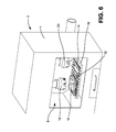
- FIG. 6 is an isometric view of the hard drive data destroyer of FIG. 1 showing the hard drive destroyer after the milling cutter is disengaged from the hard drive;
- FIG. 7 is an isometric view of the hard drive data destroyer of FIG. 1 showing the hard drive data destroyer after the destroying operation is completed;
- FIG. 8 is an isometric view of the hard drive data destroyer for SSD hard drives showing the destroyer in the loading position
- FIG. 9 is an isometric view of the hard drive data destroyer of FIG. 8 showing the vision verification
- FIG. 10 is an isometric view of the hard drive data destroyer of FIG. 8 showing the loading table positioned in the body of the milling chamber;
- FIG. 11 is an isometric view of the hard drive data destroyer of FIG. 8 showing the milling cutter engaging the hard drive;
- FIG. 12 is an isometric view of the hard drive data destroyer of FIG. 8 showing the hard drive destroyer after the milling cutter is disengaged from the hard drive;
- FIG. 13 is an isometric view of the hard drive data destroyer of FIG. 8 showing the hard drive data destroyer after the destroying operation is completed;
- FIG. 14 is an isometric view of a laser HDD hard drive data destroyer in the loading position
- FIG. 15 is an isometric view of the laser hard drive data destroyer of FIG. 14 showing the vision verification
- FIG. 16 is an isometric view of the laser hard drive data destroyer of FIG. 14 showing the loading table positioned in the laser perforating chamber;
- FIG. 17 is an isometric view of the laser hard drive data destroyer of FIG. 14 showing the laser acting on the hard drive;
- FIG. 18 is an isometric view of the laser hard drive data destroyer of FIG. 14 after completion of the laser perforation process
- FIG. 19 is an isometric view of the laser hard drive data destroyer of FIG. 14 showing the laser hard drive data destroyer after the destroying operation is completed;
- FIG. 24 is an isometric view of the laser hard drive data destroyer for SSD hard drives showing the destroyer in the loading position
- FIG. 21 is an isometric view of the laser hard drive data destroyer of FIG. 20 showing the vision verification
- FIG. 22 is an isometric view of the laser hard drive data destroyer of FIG. 20 showing the loading table positioned in the body of the milling chamber;
- FIG. 23 is an isometric view of the laser hard drive data destroyer of FIG. 20 showing the laser acting on the hard drive;
- FIG. 20 is an isometric view of the laser hard drive data destroyer of FIG. 20 after completion of the laser perforation process
- FIG. 25 is an isometric view of the laser hard drive data destroyer of FIG. 14 showing the laser hard drive data destroyer after the destroying operation is completed;
- FIG. 26 is a block diagram of the milling process of FIGS. 1-13 ;
- FIG. 27 is a block diagram of the FIG. 33 laser process of FIGS. 14-25 ;
- FIGS. 28 a -28 d are schematic plan views of an HDD and an SSD or HHD drive before and after the application of the laser;
- FIG. 29 is a schematic isometric view of a device for destroying hard drives using a spring-loaded chemical injecting system
- FIG. 30 is an isometric enlarged view of the radiator sub-assembly of the system of FIG. 29 ;
- FIG. 32 is an isometric view of the device of the injector pin sub-assembly of the system of FIG. 29 ;
- FIG. 33 is an isometric view of the temperature control plate sub-assembly of the system of device of FIG. 29 ;
- FIG. 34 is a isometric view of the system of FIG. 29 showing the injector pins released and the chemical flowing into an HHD hard drive;
- FIG. 35 is a isometric view of the system of FIG. 29 showing the injector pins released and the chemical flowing into an SSD hard drive;
- FIG. 36 is a schematic isometric view of a computer showing the placement of the system of Fig, 29 in the computer.
- FIG. 37 is a schematic isometric view of a chemical injecting system for use with laptops.
- the devices described herein can be used for destroying the data storage portion of media electronic storage devices such as HDD, HHD and SSD hard drives.
- the HDD (Hard Disc Drive) hard drive is essentially a metal platter with a magnetic coating. The coating stores the data. A read/write head on an arm accesses the data while the platters are spinning in a hard drive enclosure.
- SSD drives instead of the magnetic coating on top of platters, the data is stored on interconnected flash memory chips or pods.
- the SSD drive has no moving parts.
- the HHD (Hybrid Hard Drive) drive is a hybrid incorporating the HDD and the SSD principles. The various devices described herein can be used to destroy data on all three types of hard drives.
- FIGS. 1 and 6 show a hard drive data destroyer 2 that may include a cabinet 4 having a frontal opening 6 opening into a front loading milling chamber 8 and having a door with a safety glass window (not shown) to enclose the chamber 8 .
- a horizontally moveable table 10 is moveable on suitable rails 15 and 17 as shown in FIG. 1 a so that the table can be moved in and out of the cabinet 4 and moved in an X and Y direction to position the table within the cabinet 4 .
- the table 10 has two side by side cradles 12 and 14 for receiving and holding hard drives.
- the cradle 12 on the left is structured to receive and hold a larger 3.5 inch HDD 16 or SSD hard drive 18 and the cradle 14 on the right is structured to receive and hold a smaller 2.5 inch HDD or SSD hard drive as viewed in FIGS. 1 and 6 .
- Milling cutters 18 and 20 are mounted in suitable milling heads that may be mounted on a rail system in the cabinet 4 movement along the x-y-z axis. These milling cutters 18 and 20 may be face mill cutters modified to include a center spear 22 as described below or any other suitable milling cutter that can remove material as it is advanced downwardly along its axis and pivoted with a center spear.
- the milling cutter 18 on the left is relatively large for use with the large hard drives.
- the milling cutter 20 on the right is relatively small for use with the smaller hard drives. Although two milling cutters are shown, it is possible that just one or more than two milling cutters could be utilized.
- the milling cutters 18 and 20 are mounted in suitable spindles 21 which are driven by a motor 23 .
- the milling cutters may also be of the trepanning cutting tool type modified to include the center spear 22 as described below.
- a trepanning cutting tool may be defined generally as a cutting tool in the form of a circular tube, having teeth at one end, the work piece or tube, or both are rotated and the tube is fed axially into a workpiece, leaving behind a grooved surface in the workpiece.
- a center holding spear 22 (See FIG. 4 ) is provided one coaxial with each the milling cutters 18 and 20 .
- Each holding spear 22 is moveable in a vertical direction relative to its associated cutter 18 or 20 to extend from the center of the cutter.
- the holding spear 22 while axially moveable, is non-rotatable and can be provided with projections 24 or other sharp edges on its distal end to engage the hub of a hard drive 16 .
- a vacuum port 26 in the back wall of the cabinet 4 communicates with the milling chamber 8 and is connected to an exhaust pipe 28 and a suitable vacuum pump (not shown) to provide a vacuum system for removing debris from the milling chamber 8 .
- the 3.5 or 2.5 inch hard drive 16 is placed in a corresponding cradle 12 or 14 on the loading table 10 depending on its size.
- the larger 3.5 inch HDD or SSD hard drives are placed in the holding cradle 12 on the left as viewed in FIGS. 1 and 6 .
- the smaller 2.5 inch HDD or SSD hard drives are placed in the cradle 14 on the right.
- the placement of the hard drives corresponds with the size of the mill cutters 18 and 20 positioned within the milling chamber 8 .
- the larger cutter 18 on the left, is used to destroy 3.5 inch HDD or SSD hard drives and the smaller cutter 20 , on the right, is used to destroy 2.5 inch HDD or SSD hard drives.
- the loading process can be done automatically by placing the respective hard drives 16 or 18 in a vertical “magazine” styled loading chassis, which indexes the hard drives into an empty cradle after the previous destroying operation has been completed.
- the hard drive 16 or 18 is scanned by a suitable scanning system which may be mounted on the cabinet 4 with the scanning beam 30 directed to scan a hard drive positioned on a cradle 12 or 14 before the cradle 12 or 14 is moved into the chamber 8 .
- the scanning system may include a barcode scanner and a visioning sensor/camera that will scan the bar code, brand, serial number and will identify the hard drive by height, length and width along with identifying where the platter hub is located in the case of HDD drives.
- the information from the scanning system is fed to a computer where the information is processed and store and used to activate the CNC system position the respective milling cutter with the type of hard drive identified in the cradle 12 or 14 .
- the computer includes a database of hard drives in the market place to quickly identify and sequence the hard drive with the appropriate milling process.
- the servo and visioning system makes the necessary adjustments to complete the milling process. Then the information is saved in the database for future recognition.
- the loading table 10 is automatically activated and moves inside the body of the cabinet milling chamber 8 as shown in FIGS. 3 and 10 .
- the two-phase pneumatic milling head When the center hub 32 of the 3.5 or 2.5 inch HDD hard drive is located, the two-phase pneumatic milling head will first lower the center holding spear 22 , which applies pressure to the center hub 32 preventing the hard drive platters from spinning during the milling process as shown in FIG. 4 .
- the center holding spear 22 is not activated when destroying SSD hard drives.
- the next phase of the HDD milling process consists of lowering the outer milling cutter 18 or 20 to the surface of the 3.5 or 2.5 inch hard drive as shown in FIGS. 5 and 11 .
- the blades of the face of the milling cutter penetrate the surface of the hard drive coring-out the platter(s) of the hard drive in the case of the HDD drives.
- the milling cutter 18 When SSD hard drives are being destroyed, the milling cutter 18 is swept across the surface of the 3.5 or 2.5 inch hard drive to destroy (face mill) the area where the information pods 34 are located.
- the mill cutter 18 may be swept in a side to side, front to back or a combination of such movements in a horizontal plane.
- the cradle 12 or 14 may be moved relative to the mill cutter 18 to provide the sweeping action. In either case, such action comprises a coring and surface milling operation.
- the vacuum system is automatically activated during the milling process to collect the shards that are produced.
- the vacuum system draws the shards out of the milling chamber 8 through the exhaust port 26 and exhaust pipe 28 to an appropriate collection bin (not shown).
- the outer mill cutter 18 and center holding spear 20 retract from the surface of the hard drive as shown in FIG. 6 . All that remains is the surrounding casing of the 3.5 or 2.5 inch hard drive and the center hub, which once held the information platter(s).
- the finished product resembles a donut.
- the mill cutter 18 is retracted from the surface of the hard drive and returned to its start position. All that remains is the bottom casing of the 3.5 or 2.5 inch hard drive less the area where the information pods were located.
- a respective hard drive 16 or 18 is automatically ejected from its holding cradle 12 or 14 into a collection bin 36 below the milling chamber 8 to cool as shown in FIGS. 7 and 13 .
- the loading table 10 with the empty holding cradles 12 and 14 exits the milling chamber 8 to begin the next milling cycle.
- the milling process system is schematically shown in the block diagram shown in FIG. 26 .
- the hard drive on the cradle is scanned for recognition by the scanning system which may include a barcode sensor and a visioning sensor/camera.
- the information scanned is fed to a computer, attached to or mounted in the cabinet, and which has a data base for storing information about the hard drives.
- the computer converts the information about the hard drive in the cradle to a form to send to the CNC machine which controls the movement of the system.
- the computer may include an Ethernet port for connection to the internet along with a power supply for operating the computer, software and peripheral attachments.
- a plurality of individual hard drive destroyers 2 may be provided, each at a separate location such as individual kiosks.
- the computer provides a means for the individual destroyers 2 to communicate with each other and/or with a centralized data base.
- FIGS. 14-25 show a hard drive data destroyer 102 that utilizes a laser to destroy the drive.
- FIGS. 14-19 show the laser hard drive data destroyer operating on a HDD hard drive 104 while
- FIGS. 20-25 show the laser hard drive data destroyer operating on a SSD hard drive 106 .
- the laser hard drive data destroyer may include a cabinet 108 having a front loading laser perforating chamber with a frontal opening and a door (not shown) to close the chamber 110 .
- a horizontally moveable table 112 is moveable on suitable tracks for movement into and out of the chamber 110 .
- the table 112 has two side by side cradles 114 and 116 for receiving and holding hard drives.
- the cradle 114 on the left is structured to receive and hold a larger 3.5 inch HDD or SSD hard drive and the cradle 116 on the right is structured to receive and hold a smaller 2.5 inch HDD or SSD hard drive.
- a 3.5 or 2.5 inch hard drive is placed in a corresponding cradle 114 or 116 on the loading table 112 depending on its size.
- the larger 3.5 inch HDD or SSD hard drives are placed in the holding cradle 114 on the left as viewed in FIGS. 14 and 20 .
- the smaller 2.5 inch HDD or SSD hard drives are placed in the cradle 116 on the right.
- the loading process can be done automatically by placing the respective hard drives in a vertical “magazine” styled loading chassis, which indexes the hard drives into the empty hard drive holding chassis after the previous laser perforation cycle is complete.
- a laser head 118 is mounted in the cabinet above the table 112 .
- the laser head is moveable in the x-y-z direction to properly align with a hard drive in a cradle 112 or 116 when the table 112 with a hard drive is positioned in the chamber 110 .
- a vacuum port 120 in the back wall of the cabinet 108 communicates with the laser perforating chamber 110 and is connected to an exhaust pipe 122 and a suitable vacuum pump (not shown) to provide a vacuum system for moving debris from the perforating chamber 110 .
- Visual verification as shown in FIGS. 15 and 21 may take place after the hard drives are loaded onto the cradle.
- the barcode on the hard drive 104 or 106 is scanned by scanner 124 positioned on the cabinet to scan the bar code on the hard drive.
- the scan activates a custom x-y-z servo and visioning system to properly position the laser head 118 with the type of hard drive identified in the holding cradle 114 or 116 .
- a custom servo-visioning system may consist of a database of hard drives in the market place to quickly identify and sequence the hard drive with the appropriate laser perforation pattern. When new hard drives are introduced to the laser perforating system, the servo-visioning system makes the necessary adjustments to complete the laser perforating process. Then the information is saved in the database for future recognition.
- the loading table 112 is automatically activated and moves inside the laser perforating chamber 110 as shown in FIGS. 16 and 22 .
- the laser head 118 With the hard drive positioned in the laser perforating chamber 110 , the laser head 118 then emits either a single or multiple laser beam(s) 128 in a pulsating manner, which bore through the outer casing of 3.5 or 2.5 inch HDD and SSD hard drive.
- the laser head 118 moves while the table 112 remains in a fixed position after it is introduced into the chamber. Alternatively, the table can move and the laser head can remain stationary.
- the laser system will emit a pulsating laser(s) that produce small round holes in a grid like pattern.
- the grid like patterns will correspond with the type of hard drive being destroyed, either a HDD 3.5 or 2.5 inch or SSD 3.5 or 2.5 inch drive.
- FIGS. 28 a and 28 b which show schematically a HHD drive before and after the application of the laser respectively, the laser produces a round donut-shaped matrix 123 of small holes 125 .
- FIGS. 28 c and 28 d show schematically the before and after results of the laser on a SSD and a HHD drive wherein the matrix 127 of small holes 129 is rectangular.
- the laser perforation process can also be configured to destroy other forms of electronic media storage devices ranging from back-up tapes and DVDs to SIM cards.
- the exterior housing of the hard drive's surface is riddled with multiple holes that have penetrated the information platters of the hard drive in a grid like pattern that resembles a donut.
- the exterior housing of the hard drive's surface is riddled with multiple holes that have penetrated the information pods of the hard drive in a rectangular grid like pattern.
- the vacuum system including the exhaust port 120 communicating with the interior of the perforating chamber 110 and the exhaust pipe 122 and vacuum pump (not shown) is automatically activated during the laser perforation process to collect metal fragments that are produced and convey them to a collection bin (not shown).
- the respective hard drive is automatically ejected from the holding chassis into the collection bin below the laser perforation chamber 110 to cool as shown in FIGS. 19 and 25 .
- the loading table 112 with the empty holding cradles 114 and 116 , exits the laser perforation chamber 110 to begin the next perforation cycle.
- the laser process system is schematically shown in the block diagram shown in FIG. 27 .
- the hard drive on the cradle is scanned for recognition by the scanning system which may include a barcode sensor and a visioning sensor/camera.
- the information scanned is fed to the computer which has a data base for storing information about the hard drives.
- the computer converts the information about the hard drive in the cradle to a form to send to the CNC machine which controls the movement of the system.
- the computer may include an Ethernet port for connection to the internet along with a power supply for operating the computer, software and peripheral attachments.
- a plurality of individual laser hard drive destroyers 102 may be provided, each at a separate location such as individual kiosks.
- the computer provides a means for the individual destroyers 102 to communicate with each other and/or with a centralized data base.
- the table 10 or 112 containing the hard drive may be moved rather than the miller cutter 18 or 20 or laser head 118 , or a combination of movement.
- FIGS. 29-35 show a chemical hard drive data destroying system 202 .
- the system administers chemicals to destroy information imbedded on electronic media storage devices, such as hard disk drives (HDD), solid state drives (SSD), and hybrid hard drives (HHD), rendering the stored information digitally and forensically irretrievable.
- HDD hard disk drives
- SSD solid state drives
- HD hybrid hard drives
- the system 202 utilizes chemicals such as hydrochloric acid (HCL), ammonium nitrate (AN), and a solvent like water (H 2 O) to erode and strip away the information imbedded on the platters and/or memory pods, circuit boards, contained within the body of the respective drives 203 .
- chemicals such as hydrochloric acid (HCL), ammonium nitrate (AN), and a solvent like water (H 2 O) to erode and strip away the information imbedded on the platters and/or memory pods, circuit boards, contained within the body of the respective drives 203 .
- An additional chemical such as polyurethane (PUR), polyol resin, or similar product, can be used as a foaming agent to aid in the disbursement of the chemicals and confine the dispersions within the cavity of the hard drive.
- PUR polyurethane
- Other chemical solvents may be used as long as they are capable of destroying the data storage portion of the hard drives.
- the chemical solvent should be any suitable solvent capable of dissolving the coating of the platter(s) of an HDD drive along with a portion of the platters. In the case of SSD hard drive, the chemical solvent should be able to completely dissolve the information pods.
- the chemicals used in the destruction process are stored in self-contained pods 204 that are constructed of natural and composite materials.
- the system 202 comprises several compartmentalized sub-assemblies: a radiator 206 , a cog system 208 , an injector pin system 210 , and a temperature control plate 112 , which includes a chemical sensor pad 214 .
- the aftermarket hard drive destruction system 202 is positioned within the housing of the computer 216 customarily in the hard drive holding chassis; and mounted directly above the hard drive of the host computer as indicated in FIG. 36 .
- the sub-assemblies, which make-up the complete system, are stacked in descending order with the radiator 206 on top followed by the cog system 208 , the injector pin system 210 ; and then the temperature control plate 112 .
- the radiator can be placed in another vacant space within the computer housing to allow for more room in the hard drive holding chassis.
- the radiator 206 which works in conjunction with the temperature control plate 214 circulates radiator fluid through a closed loop system including tubing 220 connected between the radiator 206 and temperature control plate 214 to maintain an ambient temperature for the stored chemicals.
- the radiator does not have to be used if the host computer is deployed in an environment where the ambient temperature is compatible with the system's chemicals. Rather than a radiator fluid being circulated, air may be circulated.
- the cog system 208 houses the drive mechanism that simultaneously drives the injector pins in the form of four hollow drill bits 222 through the chemical pods 204 stored in the temperature control plate 212 , and into the cavity of the hard drive.
- the depth of the penetration of the drill bits 222 is pre-calibrated to the specific type of hard drive installed in the computer 216 .
- the cog system 208 includes four toothed cog wheels 224 operably connected one to each of the four drill bits 222 .
- a center cog wheel 226 drives the cog wheels 224 and is driven by drive motor 228 .
- the drill bits 222 are held above the chemical pods 204 until the system is activated.
- the injector pin system 210 consists of four chambers 230 each with a spring loaded plunger 234 that drives the chemicals stored inside the chemical pods 204 through the hollow shafts of the drill bit 222 , and into the cavity of the hard drive.
- the plungers 234 are held in their raised or cocked position against the bias of the spring 235 by a release mechanism (not shown).
- the chambers 230 are an open ended cylinder with the open bottom end disposed in the frustoconical openings 235 in the temperature control plate 212 in which the chemical pods 204 are located, While the drawings show four chambers 230 , additional chambers 210 can be used to aid in the disbursement of the chemical solvent. In the case of the smaller 2.5 inch laptop hard drives, as few as one chamber may be utilized.
- An auxiliary air system using carbon dioxide (CO 2 ) cartridges or dedicated air line, can be integrated through the injector pin system 210 to assist with the chemical dispersion in the hard drive cavity.
- the injector pin system 210 can also be adapted to disburse chemicals that are stored outside the system, thus bypassing the use of chemical pods.
- the temperature control plate 214 houses the second half of the radiator's closed loop system, which is connected with external tubing 220 .
- the tubing 220 extends around the exterior of the cog system 202 and the injector pin system 218 and extends through the temperature control plate 214 around the frustoconical openings 235 as shown in FIG. 33 .
- the temperature control plate 214 also serves as the bottom portion of the four injector pin chambers 230 , which house the four (4) conical shaped chemical pods. Threaded connecting rods (not shown) are used to securely fasten the injector pin system to the temperature control plate.
- a chemical sensor pad 232 is attached to the bottom of the temperature control plate 214 .
- the chemical sensor pad 232 serves to detect the premature release of chemicals as a safety precaution.
- the chemical sensor pad 232 may be connected to the mother board of the computer to provide a warning in the event of released chemicals.
- the chemical system 202 is activated at the key board or from a remote location; both of which can be individually or collectively deactivated for additional security purposes.
- the drill bits 222 are activated and advanced against the hard drive 203 to pierce the body of the hard drive and enter the cavity in which the data storage portion is located.
- a release mechanism then releases the loaded spring(s) 235 which drives the plungers 234 downward against the chemical pods 204 .
- the process of the releasing the plungers 234 forces the chemical solvent out of the chemical pod 204 through holes in the tubular drills bits 22 and forces the chemical solvent through the pointed tip 236 of the drill bits 222 into the cavity of the hard drives.
- a single or multi step “bore and inject” method can be used to introduce the chemical solvent into the body of the hard drive.
- the chemical solvent 238 begins to disburse from the drill tip 236 throughout the internal cavity of the hard drive.
- the platter(s) within the HDD hard drive will still be spinning, which aids in the disbursement of the chemical solvent coating the information platter(s).
- a foaming agent in the chemical solvent 238 will further aid in the disbursement of the chemical solvent 238 and restrict the disbursement within the cavity of the hard drive 203 a.
- the expanding nature of the foaming agent will also serve as a seal to restrict the chemical solvent 238 from spreading outside the inner casing of the hard drive.
- the information stored in the HDD hard drive 203 a is completely destroyed, but the computer can be used again by installing a new hard drive.
- the chemical solvent 238 begins to disburse throughout the internal cavity coating the information pods of the SSD hard drive 203 b.
- a foaming agent may also be included in the chemical solvent to further aid in the disbursement of the chemical solvent and restrict the disbursement within the cavity of the hard drive.
- the information stored in the SSD hard drive 203 b is completely destroyed, but the computer can be used again by installing a new hard drive.
- the sub-assemblies can be reconfigured to adapt to horizontal computer units with limited space above the hard drive.
- FIG. 36 depicts the exterior of a smaller more compact spring loaded chemical data destroying system 300 for smaller 2.5 inch HDD and SSD hard drives such as used in laptops.
- the sub-assemblies are thinner than the counterparts previously described.
- the chemical destruction system can be adapted to destroy other electronic media storage devices in smart phone, cell phones and tablets.
- the hard drives are processed with their covers remaining on.
- the covers have been shown removed in the drawings to differentiate the types of hard drives being processed.
- the three devices may be designed for “desktop” use and utilize a standard 110 volt power source. However, more industrialized versions may utilize a 220 volt source. All three devices may be adapted to accommodate all types of electronic media storage devices.
Landscapes
- Engineering & Computer Science (AREA)
- Mechanical Engineering (AREA)
- Physics & Mathematics (AREA)
- Optics & Photonics (AREA)
- Plasma & Fusion (AREA)
- Laser Beam Processing (AREA)
- Food Science & Technology (AREA)
- Crushing And Pulverization Processes (AREA)
- Health & Medical Sciences (AREA)
- Toxicology (AREA)
- Processing Of Solid Wastes (AREA)
Priority Applications (6)
| Application Number | Priority Date | Filing Date | Title |
|---|---|---|---|
| US14/206,234 US9440313B2 (en) | 2013-03-12 | 2014-03-12 | Hard drive data destroying device |
| PCT/US2014/050523 WO2015137992A1 (fr) | 2013-03-12 | 2014-08-11 | Dispositif de destruction de données de lecteur de disque dur |
| EP14885547.1A EP3116652B1 (fr) | 2013-03-12 | 2014-08-11 | Dispositif de destruction de données de lecteur de disque dur |
| CA2942329A CA2942329C (fr) | 2013-03-12 | 2014-08-11 | Dispositif de destruction de donnees de lecteur de disque dur |
| US15/223,444 US9959889B2 (en) | 2013-03-12 | 2016-07-29 | Hard drive data destroying device |
| US15/928,852 US11107495B2 (en) | 2013-03-12 | 2018-03-22 | Laser destruction system for hard drives |
Applications Claiming Priority (2)
| Application Number | Priority Date | Filing Date | Title |
|---|---|---|---|
| US201361777091P | 2013-03-12 | 2013-03-12 | |
| US14/206,234 US9440313B2 (en) | 2013-03-12 | 2014-03-12 | Hard drive data destroying device |
Related Child Applications (1)
| Application Number | Title | Priority Date | Filing Date |
|---|---|---|---|
| US15/223,444 Division US9959889B2 (en) | 2013-03-12 | 2016-07-29 | Hard drive data destroying device |
Publications (2)
| Publication Number | Publication Date |
|---|---|
| US20140263216A1 US20140263216A1 (en) | 2014-09-18 |
| US9440313B2 true US9440313B2 (en) | 2016-09-13 |
Family
ID=51522882
Family Applications (3)
| Application Number | Title | Priority Date | Filing Date |
|---|---|---|---|
| US14/206,234 Active 2034-11-15 US9440313B2 (en) | 2013-03-12 | 2014-03-12 | Hard drive data destroying device |
| US15/223,444 Active US9959889B2 (en) | 2013-03-12 | 2016-07-29 | Hard drive data destroying device |
| US15/928,852 Active 2034-11-24 US11107495B2 (en) | 2013-03-12 | 2018-03-22 | Laser destruction system for hard drives |
Family Applications After (2)
| Application Number | Title | Priority Date | Filing Date |
|---|---|---|---|
| US15/223,444 Active US9959889B2 (en) | 2013-03-12 | 2016-07-29 | Hard drive data destroying device |
| US15/928,852 Active 2034-11-24 US11107495B2 (en) | 2013-03-12 | 2018-03-22 | Laser destruction system for hard drives |
Country Status (4)
| Country | Link |
|---|---|
| US (3) | US9440313B2 (fr) |
| EP (1) | EP3116652B1 (fr) |
| CA (1) | CA2942329C (fr) |
| WO (1) | WO2015137992A1 (fr) |
Cited By (4)
| Publication number | Priority date | Publication date | Assignee | Title |
|---|---|---|---|---|
| US20170303442A1 (en) * | 2014-06-24 | 2017-10-19 | David Lane Smith | System and method for fluid cooling of electronic devices installed in a sealed enclosure |
| US10657345B1 (en) * | 2019-07-02 | 2020-05-19 | Phiston Technologies, Inc. | Media destruction verification apparatus |
| US11191186B2 (en) | 2014-06-24 | 2021-11-30 | David Lane Smith | System and method for fluid cooling of electronic devices installed in an enclosure |
| US11744041B2 (en) | 2014-06-24 | 2023-08-29 | David Lane Smith | System and method for fluid cooling of electronic devices installed in an enclosure |
Families Citing this family (30)
| Publication number | Priority date | Publication date | Assignee | Title |
|---|---|---|---|---|
| US9440313B2 (en) | 2013-03-12 | 2016-09-13 | Serenity Data Security, Llc | Hard drive data destroying device |
| EP2835759B1 (fr) * | 2013-08-08 | 2019-03-27 | GbR Oliver Oechsle, Dr. Hans-Peter Dietz | Procédé et système de manipulation d'un terminal utile électronique défectueux |
| EP3012065B1 (fr) * | 2014-10-22 | 2020-07-15 | Ivoclar Vivadent AG | Machine-outil dentaire |
| US11337783B2 (en) | 2014-10-22 | 2022-05-24 | Ivoclar Vivadent Ag | Dental machine tool |
| US9488452B1 (en) | 2015-04-22 | 2016-11-08 | Battelle Energy Alliance, Llc | Apparatus for rendering at least a portion of a device inoperable and related methods |
| US10055596B1 (en) * | 2015-06-08 | 2018-08-21 | Amazon Technologies, Inc. | Data protection system |
| US9928386B1 (en) | 2015-06-08 | 2018-03-27 | Amazon Technologies, Inc. | Data protection system |
| US10675635B1 (en) * | 2015-06-11 | 2020-06-09 | Amazon Technologies, Inc. | Hardware sanitization and destruction machine |
| WO2017004573A1 (fr) * | 2015-07-02 | 2017-01-05 | Serenity Data Services, Inc. | Vérification de produit pour dispositif de destruction de données de disque dur |
| CA2991238A1 (fr) * | 2015-07-02 | 2017-01-05 | Serenity Data Services, Inc. | Systeme de demontage de lecteur de disque dur |
| US11167384B2 (en) * | 2015-07-02 | 2021-11-09 | Serenity Data Security, Llc | Hard drive non-destructive dismantling system |
| US10589286B2 (en) * | 2015-08-20 | 2020-03-17 | Akamai Technologies, Inc. | Efficiently sanitizing a solid state drive (SSD) |
| KR101715215B1 (ko) * | 2016-04-29 | 2017-03-10 | 우연오 | 반도체 저장장치의 훼손장치 |
| CN106270638B (zh) * | 2016-06-02 | 2018-03-09 | 常州市金海珑机械制造有限公司 | 一种五金件钻孔用定位装置 |
| US10558192B2 (en) | 2016-06-03 | 2020-02-11 | William Wilder | Movable gantry system configured to interface with jigs of different sizes |
| US10324889B2 (en) * | 2016-08-07 | 2019-06-18 | Demand Peripherals, Inc. | System and method to tolerate ringing on a serial data bus |
| US10449612B2 (en) * | 2016-10-24 | 2019-10-22 | Steel 21, LLC | Methods of milling a piece of raw steel stock into a machine-ready piece of steel |
| EP3518058B1 (fr) * | 2018-01-26 | 2021-03-03 | Klingelnberg GmbH | Procédé de positionnement automatisé d'une pièce à usiner dentée et système de fabrication destiné à la mise en uvre dudit procédé |
| US11243710B1 (en) | 2018-04-02 | 2022-02-08 | Dominic B. Picone | System and method for remote drive destruction |
| CN110124816A (zh) * | 2019-05-14 | 2019-08-16 | 陈绪忠 | 一种硬盘粉碎销毁机及其工作方法 |
| CN110124821B (zh) * | 2019-05-18 | 2020-11-06 | 池州灵芝化建材料科技有限公司 | 一种原矿自动分目磨碎收集装置及使用方法 |
| KR20210004552A (ko) * | 2019-07-05 | 2021-01-13 | 주식회사 엘지화학 | 흄 제거 기능이 구비된 용접장치 |
| CN110866279B (zh) * | 2019-11-15 | 2023-04-07 | 北京工业大学 | 一种基于废旧电子产品特征的信息清除参数获取方法 |
| CN111230175A (zh) * | 2020-01-16 | 2020-06-05 | 季荣英 | 一种电子元器件加工装置及操作方法 |
| US11643271B2 (en) * | 2020-03-23 | 2023-05-09 | Oracle International Corporation | Secure destruction bin |
| CN111975067B (zh) * | 2020-07-29 | 2021-12-07 | 黄朋飞 | 一种水平双头竖直移动式铣削装置 |
| US11257513B1 (en) * | 2020-08-20 | 2022-02-22 | Simon Levin | Data removal drill device and method to use |
| CN112549571A (zh) * | 2020-11-20 | 2021-03-26 | 江西亚中电子科技股份有限公司 | 一种提升透镜生产效率的装置及其工艺 |
| CN112705335A (zh) * | 2020-12-30 | 2021-04-27 | 庞江涛 | 一种便于废料回收的花键轴传动轴生产用打孔设备 |
| CN112846870B (zh) * | 2020-12-31 | 2022-04-19 | 北京质信捷机电设备有限公司 | 一种具有废料回收功能的铣削夹具 |
Citations (44)
| Publication number | Priority date | Publication date | Assignee | Title |
|---|---|---|---|---|
| US2234663A (en) | 1935-09-21 | 1941-03-11 | Frederick O Anderegg | Method of reinforcing building units |
| US2980151A (en) * | 1957-12-19 | 1961-04-18 | Arbour Box Company | Machine for cutting billets from a block |
| US3237362A (en) | 1961-07-11 | 1966-03-01 | Howard A Fromson | Structural unit for supporting loads and resisting stresses |
| US3587391A (en) * | 1969-09-25 | 1971-06-28 | Robert D Pitts | Work support mechanism |
| US4721257A (en) | 1986-12-04 | 1988-01-26 | Williams Patent Crusher And Pulverizer Company | Rotary shredding apparatus |
| US4779810A (en) | 1986-06-20 | 1988-10-25 | 683462 Ontario Limited | Shredding machine |
| US4880065A (en) | 1988-10-14 | 1989-11-14 | Gas Research Institute | Air motor operated rotary earth drilling tool |
| US5064126A (en) | 1987-05-06 | 1991-11-12 | Formark Pty. Limited | Shredder |
| US5203067A (en) * | 1991-05-22 | 1993-04-20 | Defazio August | Reuse of plastic |
| US5236139A (en) | 1992-08-10 | 1993-08-17 | Ameri-Shred Industrial Corp. | Wear adjustable shredder |
| US5930217A (en) | 1996-06-28 | 1999-07-27 | Victor Company Of Japan, Ltd. | Optical information recording/reproducing system, optical information storage medium, and manufacturing method thereof |
| US6039637A (en) | 1998-05-15 | 2000-03-21 | Cd-Rom Usa, Inc. | Security device for destroying the information bearing layer and data of a compact disc |
| US6065911A (en) * | 1994-12-22 | 2000-05-23 | Almblad; Robert | Method and apparatus for automatically making keys |
| US6375106B1 (en) | 2000-05-18 | 2002-04-23 | Ssi Shredding Systems, Inc. | Waste reduction machine with replaceable teeth |
| US6478515B1 (en) * | 1998-04-03 | 2002-11-12 | The Hillman Group, Inc. | Inscribing system |
| US6588691B2 (en) | 2001-08-31 | 2003-07-08 | Shred-Tech Inc. | Mobile document shredder with retractable loading tunnel and load cell |
| US20030213531A1 (en) | 2002-05-17 | 2003-11-20 | Conry Patrick M. | Article scanning method and apparatus for computer-controlled sawing machines |
| US6685119B2 (en) | 2000-03-01 | 2004-02-03 | Charles Castronovo | High-security data removal process for data-containing disks, portable machine for high-speed, high security disk data removal, and DVD splitting process and apparatus |
| US6695240B2 (en) | 2001-05-10 | 2004-02-24 | Shredfast, Inc. | Shredding apparatus |
| US20040050420A1 (en) | 2002-09-12 | 2004-03-18 | Macronix International Co., Ltd. | Method for detecting solvent leakage during manufacture of a semiconductor device |
| US20040252628A1 (en) | 2003-03-18 | 2004-12-16 | Roger Detzler | Dead on demand disk technology |
| US20050257049A1 (en) | 2004-03-18 | 2005-11-17 | University Of New Hampshire | Chemical for data destruction |
| US20060072244A1 (en) | 2004-10-06 | 2006-04-06 | Rapp Robert J | Methods for modifying or building a disk drive such that a substance is introduced into a disk drive enclosure with the intent to protect, to damage, or to destroy the disk drive and disk drive's data |
| US7090214B2 (en) | 2001-12-26 | 2006-08-15 | Castronovo Charles A | Feeding mechanism |
| US7198213B2 (en) | 2004-08-13 | 2007-04-03 | Vecoplan, Llc | Mobile shredder |
| US7204436B2 (en) | 2001-12-26 | 2007-04-17 | Castronovo Charles A | Residue exit for security destruction machines |
| US7308543B2 (en) | 2005-03-22 | 2007-12-11 | International Business Machines Corporation | Method and system for shredding data within a data storage subsystem |
| US7311277B2 (en) | 2002-08-28 | 2007-12-25 | Fuji Xerox, Co., Ltd. | Shredder apparatus and shredding method |
| US7363317B2 (en) | 2005-02-15 | 2008-04-22 | International Business Machines Corporation | Memory efficient XML shredding with partial commit |
| US20080175684A1 (en) * | 2006-07-24 | 2008-07-24 | Deckel Maho Seebach Gmbh | Milling and drilling machine |
| US7427040B2 (en) | 2001-12-26 | 2008-09-23 | Castronovo Charles A | No-oil shredder and other no-oil machinery |
| US20090127341A1 (en) | 2007-11-19 | 2009-05-21 | Xiangyang Feng | Bar-code reading tool |
| US7562836B2 (en) | 2004-05-03 | 2009-07-21 | Jody Langston | Apparatus, system, and method for condensing, separating and storing recyclable material |
| US7588206B2 (en) | 2003-12-31 | 2009-09-15 | Armex, Inc. | Material processing apparatus and methods |
| US7607598B2 (en) | 2001-12-26 | 2009-10-27 | Castronovo Charles A | Self-healing cutting apparatus and other self-healing machinery |
| US20100145498A1 (en) * | 2008-12-04 | 2010-06-10 | Honda Motor Co., Ltd. | Tool stocker, machine tool system, and tool damage detecting apparatus |
| US7753762B2 (en) * | 2005-06-30 | 2010-07-13 | D3, Inc. | Optical disc destruction device |
| US20100294865A1 (en) | 2009-05-23 | 2010-11-25 | Scott Anthony Wozny | Hard drive destruction system |
| US20110069322A1 (en) | 2009-09-21 | 2011-03-24 | Faro Technologies, Inc. | Laser pointing mechanism |
| US20110085863A1 (en) * | 2009-10-09 | 2011-04-14 | Cheng Hsiu Shih | Multi-spindle machining machine |
| US20110305250A1 (en) | 2010-03-05 | 2011-12-15 | TeraDiode, Inc. | Wavelength beam combining based pulsed lasers |
| US20120091237A1 (en) | 2010-10-13 | 2012-04-19 | Clark Kevin P | Hard Drive Shredding Device |
| WO2012137063A2 (fr) | 2011-04-07 | 2012-10-11 | Dynamic Micro Systems | Procédés et appareils de revêtement au rouleau |
| US20130124620A1 (en) | 2007-05-10 | 2013-05-16 | Research In Motion Limited | System and method for device management |
Family Cites Families (45)
| Publication number | Priority date | Publication date | Assignee | Title |
|---|---|---|---|---|
| US2745319A (en) | 1953-01-14 | 1956-05-15 | William F Sawyer | Cam milling attachment for milling machines |
| JPS58170037A (ja) * | 1982-03-31 | 1983-10-06 | Toshiba Corp | 配線の切断方法及び切断装置 |
| US4493967A (en) * | 1982-09-01 | 1985-01-15 | Westinghouse Electric Corp. | Rigid support for laser machining apparatus |
| JPS59143616U (ja) | 1983-03-14 | 1984-09-26 | 萬デザイン株式会社 | 環状カツタ− |
| JPS61214964A (ja) | 1985-03-20 | 1986-09-24 | Ngk Insulators Ltd | 面取り装置 |
| FR2640535B1 (fr) | 1988-12-19 | 1994-07-08 | Aerospatiale | Outil a trepaner de precision pour des panneaux en materiau sandwich |
| US5149948A (en) | 1990-07-16 | 1992-09-22 | Computer Identics | Improved bar code reader system for reading bar codes under high specular reflection conditions with a variety of surface effects |
| US5074722A (en) | 1991-03-15 | 1991-12-24 | Greenlee Textron Inc. | Hole cutter |
| US6047875A (en) | 1995-09-20 | 2000-04-11 | Unitek Miyachi Coporation | Reflow soldering self-aligning fixture |
| WO1997028924A1 (fr) * | 1996-02-12 | 1997-08-14 | Georgeann Mc Fadden | Dispositif de destruction de disque compact |
| US5871313A (en) | 1996-10-01 | 1999-02-16 | International Business Machines Corporation | Precise self-aligning chamfer method and apparatus |
| US6137893A (en) | 1996-10-07 | 2000-10-24 | Cognex Corporation | Machine vision calibration targets and methods of determining their location and orientation in an image |
| GB2329298A (en) | 1997-09-16 | 1999-03-17 | Mitel Corp | Visually displaying computer telephony options at caller's telephone device |
| US6912775B1 (en) | 1998-02-25 | 2005-07-05 | Seagate Technology Llc | Assembly device for assembling components |
| US6311100B1 (en) | 1998-09-14 | 2001-10-30 | Mass. Institute Of Technology | Tool path generator for computer aided manufacturing |
| US6089434A (en) | 1999-02-26 | 2000-07-18 | Gleason Brothers Industries Inc. | Automatic frame maker |
| US6725184B1 (en) | 1999-06-30 | 2004-04-20 | Wisconsin Alumni Research Foundation | Assembly and disassembly sequences of components in computerized multicomponent assembly models |
| FR2799680B1 (fr) | 1999-10-14 | 2001-12-14 | Japp Inventeurs | Machine automatique d'assemblage de cadres |
| DE19950079B4 (de) * | 1999-10-18 | 2004-08-19 | Thyssenkrupp Technologies Ag | Verfahren und Vorrichtung zum Bearbeiten von Bauteilen |
| US7043055B1 (en) | 1999-10-29 | 2006-05-09 | Cognex Corporation | Method and apparatus for locating objects using universal alignment targets |
| MY127032A (en) | 1999-12-28 | 2006-11-30 | Hitachi Metals Ltd | Work chamfering apparatus and work chamfering method |
| JP3946438B2 (ja) | 2000-01-26 | 2007-07-18 | 有限会社データンク | 円盤状記憶媒体の供給装置 |
| IT1319864B1 (it) | 2000-03-17 | 2003-11-03 | Giuseppe Raffoni | Dispositivo per attuare nelle apparecchiature che realizzano cornicirettangolari, il perfetto accostamento dei listelli da unire in |
| JP3877501B2 (ja) | 2000-07-07 | 2007-02-07 | 松下電器産業株式会社 | 部品認識データ作成方法及び作成装置並びに電子部品実装装置及び記録媒体 |
| US6752687B2 (en) | 2001-04-30 | 2004-06-22 | International Business Machines Corporation | Method of polishing disks |
| DK1412725T3 (en) * | 2001-06-29 | 2019-03-25 | Meso Scale Technologies Llc | Multi-well plates for LUMINESCENSE TEST MEASUREMENTS |
| US6848113B2 (en) | 2001-07-02 | 2005-01-25 | Amtren Corporation | Optical media pick and process |
| DE10304903A1 (de) * | 2003-02-06 | 2004-10-28 | Siemens Ag | Vorrichtung zur Automatisierung und/oder Steuerung von Werkzeug- oder Produktionsmaschinen |
| US7016117B2 (en) * | 2003-04-10 | 2006-03-21 | Hitachi Via Mechanics, Ltd. | Radially non-symmetric beam forming elements for correction of energy profile distortion due to lateral beam drift |
| EP1712304A4 (fr) | 2004-03-31 | 2008-05-14 | Orient Instr Comp Co Ltd | Dispositif de destruction de support d'enregistrement, systeme de destruction de support d'enregistrement, dispositif de controle d'appareil electronique et programme informatique |
| US20070063082A1 (en) | 2005-09-19 | 2007-03-22 | Coleman Brian B | Method, device, system, and program for the implementation of shredding |
| EP1931495A4 (fr) * | 2005-10-03 | 2009-08-26 | Aradigm Corp | Procede et systeme d'usinage laser |
| US8229593B2 (en) | 2005-10-03 | 2012-07-24 | International Business Machines Corporation | Document destruction management |
| JP5213334B2 (ja) | 2006-01-17 | 2013-06-19 | ガジック・テクニカル・エンタープライゼス | 磁気ヘッド及びディスク試験用スピンスタンドのための自動化ディスククランピング方法 |
| US7761183B2 (en) | 2006-02-13 | 2010-07-20 | Sullivan Douglas G | Methods and systems for producing numerical control program files for controlling machine tools |
| US7628865B2 (en) * | 2006-04-28 | 2009-12-08 | Asml Netherlands B.V. | Methods to clean a surface, a device manufacturing method, a cleaning assembly, cleaning apparatus, and lithographic apparatus |
| JP4797939B2 (ja) | 2006-11-07 | 2011-10-19 | 富士ゼロックス株式会社 | 廃棄証明出力装置および廃棄証明出力プログラム |
| US20080116182A1 (en) * | 2006-11-21 | 2008-05-22 | Palo Alto Research Center Incorporated | Multiple Station Scan Displacement Invariant Laser Ablation Apparatus |
| ITPD20070201A1 (it) * | 2007-06-08 | 2008-12-09 | Helios Technology Societa A Re | Macchina per la rimozione di superfici di semiconduttori, ed in particolare di superfici con circuiti integrati |
| US20090089031A1 (en) * | 2007-09-28 | 2009-04-02 | Rockwell Automation Technologies, Inc. | Integrated simulation of controllers and devices |
| US9619332B2 (en) * | 2007-10-01 | 2017-04-11 | International Business Machines Corporation | Method and system for efficiently managing content on an information handling device |
| US9141105B2 (en) * | 2008-07-23 | 2015-09-22 | Hurco Companies, Inc. | Method and apparatus for monitoring or controlling a machine tool system |
| US7667923B1 (en) | 2009-07-07 | 2010-02-23 | International Business Machines Corporation | Hard drive data platter impairment tool |
| PL2619633T3 (pl) * | 2010-09-25 | 2024-04-29 | Ipg Photonics (Canada) Inc. | Sposób obrazowania koherentnego i kontroli informacji zwrotnej do modyfikowania materiałów |
| US9440313B2 (en) | 2013-03-12 | 2016-09-13 | Serenity Data Security, Llc | Hard drive data destroying device |
-
2014
- 2014-03-12 US US14/206,234 patent/US9440313B2/en active Active
- 2014-08-11 CA CA2942329A patent/CA2942329C/fr active Active
- 2014-08-11 WO PCT/US2014/050523 patent/WO2015137992A1/fr active Application Filing
- 2014-08-11 EP EP14885547.1A patent/EP3116652B1/fr active Active
-
2016
- 2016-07-29 US US15/223,444 patent/US9959889B2/en active Active
-
2018
- 2018-03-22 US US15/928,852 patent/US11107495B2/en active Active
Patent Citations (52)
| Publication number | Priority date | Publication date | Assignee | Title |
|---|---|---|---|---|
| US2234663A (en) | 1935-09-21 | 1941-03-11 | Frederick O Anderegg | Method of reinforcing building units |
| US2980151A (en) * | 1957-12-19 | 1961-04-18 | Arbour Box Company | Machine for cutting billets from a block |
| US3237362A (en) | 1961-07-11 | 1966-03-01 | Howard A Fromson | Structural unit for supporting loads and resisting stresses |
| US3587391A (en) * | 1969-09-25 | 1971-06-28 | Robert D Pitts | Work support mechanism |
| US4779810A (en) | 1986-06-20 | 1988-10-25 | 683462 Ontario Limited | Shredding machine |
| US4721257A (en) | 1986-12-04 | 1988-01-26 | Williams Patent Crusher And Pulverizer Company | Rotary shredding apparatus |
| US5064126A (en) | 1987-05-06 | 1991-11-12 | Formark Pty. Limited | Shredder |
| US4880065A (en) | 1988-10-14 | 1989-11-14 | Gas Research Institute | Air motor operated rotary earth drilling tool |
| US5203067A (en) * | 1991-05-22 | 1993-04-20 | Defazio August | Reuse of plastic |
| US5236139A (en) | 1992-08-10 | 1993-08-17 | Ameri-Shred Industrial Corp. | Wear adjustable shredder |
| US6065911A (en) * | 1994-12-22 | 2000-05-23 | Almblad; Robert | Method and apparatus for automatically making keys |
| US5930217A (en) | 1996-06-28 | 1999-07-27 | Victor Company Of Japan, Ltd. | Optical information recording/reproducing system, optical information storage medium, and manufacturing method thereof |
| US6478515B1 (en) * | 1998-04-03 | 2002-11-12 | The Hillman Group, Inc. | Inscribing system |
| US6039637A (en) | 1998-05-15 | 2000-03-21 | Cd-Rom Usa, Inc. | Security device for destroying the information bearing layer and data of a compact disc |
| US6685119B2 (en) | 2000-03-01 | 2004-02-03 | Charles Castronovo | High-security data removal process for data-containing disks, portable machine for high-speed, high security disk data removal, and DVD splitting process and apparatus |
| US6375106B1 (en) | 2000-05-18 | 2002-04-23 | Ssi Shredding Systems, Inc. | Waste reduction machine with replaceable teeth |
| US6695240B2 (en) | 2001-05-10 | 2004-02-24 | Shredfast, Inc. | Shredding apparatus |
| US6588691B2 (en) | 2001-08-31 | 2003-07-08 | Shred-Tech Inc. | Mobile document shredder with retractable loading tunnel and load cell |
| US7175116B2 (en) | 2001-12-26 | 2007-02-13 | Castronovo Charles A | High-security cutting |
| US7240864B2 (en) | 2001-12-26 | 2007-07-10 | Castronovo Charles A | Helical cutting |
| US7607598B2 (en) | 2001-12-26 | 2009-10-27 | Castronovo Charles A | Self-healing cutting apparatus and other self-healing machinery |
| US7448562B2 (en) | 2001-12-26 | 2008-11-11 | Castronovo Charles A | High-security destruction including sacrificial cutting followed by non-sacrificial cutting |
| US7427040B2 (en) | 2001-12-26 | 2008-09-23 | Castronovo Charles A | No-oil shredder and other no-oil machinery |
| US7090214B2 (en) | 2001-12-26 | 2006-08-15 | Castronovo Charles A | Feeding mechanism |
| US7090156B2 (en) | 2001-12-26 | 2006-08-15 | Castronovo Charles A | Destroying planar material |
| US7100852B2 (en) | 2001-12-26 | 2006-09-05 | Castronovo Charles A | Helical cutting |
| US7357340B2 (en) | 2001-12-26 | 2008-04-15 | Castronovo Charles A | Destruction method with 45 degree feeding |
| US7334747B2 (en) | 2001-12-26 | 2008-02-26 | Castronovo Charles A | Destroying planar material into high security pieces |
| US7204436B2 (en) | 2001-12-26 | 2007-04-17 | Castronovo Charles A | Residue exit for security destruction machines |
| US20030213531A1 (en) | 2002-05-17 | 2003-11-20 | Conry Patrick M. | Article scanning method and apparatus for computer-controlled sawing machines |
| US7311277B2 (en) | 2002-08-28 | 2007-12-25 | Fuji Xerox, Co., Ltd. | Shredder apparatus and shredding method |
| US20040050420A1 (en) | 2002-09-12 | 2004-03-18 | Macronix International Co., Ltd. | Method for detecting solvent leakage during manufacture of a semiconductor device |
| US20040252628A1 (en) | 2003-03-18 | 2004-12-16 | Roger Detzler | Dead on demand disk technology |
| US7588206B2 (en) | 2003-12-31 | 2009-09-15 | Armex, Inc. | Material processing apparatus and methods |
| US20050257049A1 (en) | 2004-03-18 | 2005-11-17 | University Of New Hampshire | Chemical for data destruction |
| US7562836B2 (en) | 2004-05-03 | 2009-07-21 | Jody Langston | Apparatus, system, and method for condensing, separating and storing recyclable material |
| US7198213B2 (en) | 2004-08-13 | 2007-04-03 | Vecoplan, Llc | Mobile shredder |
| US20060072244A1 (en) | 2004-10-06 | 2006-04-06 | Rapp Robert J | Methods for modifying or building a disk drive such that a substance is introduced into a disk drive enclosure with the intent to protect, to damage, or to destroy the disk drive and disk drive's data |
| US7363317B2 (en) | 2005-02-15 | 2008-04-22 | International Business Machines Corporation | Memory efficient XML shredding with partial commit |
| US7308543B2 (en) | 2005-03-22 | 2007-12-11 | International Business Machines Corporation | Method and system for shredding data within a data storage subsystem |
| US7753762B2 (en) * | 2005-06-30 | 2010-07-13 | D3, Inc. | Optical disc destruction device |
| US20080175684A1 (en) * | 2006-07-24 | 2008-07-24 | Deckel Maho Seebach Gmbh | Milling and drilling machine |
| US20130124620A1 (en) | 2007-05-10 | 2013-05-16 | Research In Motion Limited | System and method for device management |
| US20090127341A1 (en) | 2007-11-19 | 2009-05-21 | Xiangyang Feng | Bar-code reading tool |
| US20100145498A1 (en) * | 2008-12-04 | 2010-06-10 | Honda Motor Co., Ltd. | Tool stocker, machine tool system, and tool damage detecting apparatus |
| US20100294865A1 (en) | 2009-05-23 | 2010-11-25 | Scott Anthony Wozny | Hard drive destruction system |
| US20120292415A1 (en) | 2009-05-23 | 2012-11-22 | Scott Anthony Wozny | Hard drive destruction system |
| US20110069322A1 (en) | 2009-09-21 | 2011-03-24 | Faro Technologies, Inc. | Laser pointing mechanism |
| US20110085863A1 (en) * | 2009-10-09 | 2011-04-14 | Cheng Hsiu Shih | Multi-spindle machining machine |
| US20110305250A1 (en) | 2010-03-05 | 2011-12-15 | TeraDiode, Inc. | Wavelength beam combining based pulsed lasers |
| US20120091237A1 (en) | 2010-10-13 | 2012-04-19 | Clark Kevin P | Hard Drive Shredding Device |
| WO2012137063A2 (fr) | 2011-04-07 | 2012-10-11 | Dynamic Micro Systems | Procédés et appareils de revêtement au rouleau |
Non-Patent Citations (1)
| Title |
|---|
| Search Report, from PCT/US14/50523, mailed Jan. 6, 2015. |
Cited By (5)
| Publication number | Priority date | Publication date | Assignee | Title |
|---|---|---|---|---|
| US20170303442A1 (en) * | 2014-06-24 | 2017-10-19 | David Lane Smith | System and method for fluid cooling of electronic devices installed in a sealed enclosure |
| US10045467B2 (en) * | 2014-06-24 | 2018-08-07 | David Lane Smith | System and method for fluid cooling of electronic devices installed in a sealed enclosure |
| US11191186B2 (en) | 2014-06-24 | 2021-11-30 | David Lane Smith | System and method for fluid cooling of electronic devices installed in an enclosure |
| US11744041B2 (en) | 2014-06-24 | 2023-08-29 | David Lane Smith | System and method for fluid cooling of electronic devices installed in an enclosure |
| US10657345B1 (en) * | 2019-07-02 | 2020-05-19 | Phiston Technologies, Inc. | Media destruction verification apparatus |
Also Published As
| Publication number | Publication date |
|---|---|
| CA2942329C (fr) | 2022-10-04 |
| CA2942329A1 (fr) | 2015-09-17 |
| US11107495B2 (en) | 2021-08-31 |
| EP3116652A4 (fr) | 2017-11-15 |
| EP3116652A1 (fr) | 2017-01-18 |
| US20140263216A1 (en) | 2014-09-18 |
| US9959889B2 (en) | 2018-05-01 |
| WO2015137992A1 (fr) | 2015-09-17 |
| US20180218751A1 (en) | 2018-08-02 |
| US20160336027A1 (en) | 2016-11-17 |
| EP3116652B1 (fr) | 2022-03-16 |
Similar Documents
| Publication | Publication Date | Title |
|---|---|---|
| US11107495B2 (en) | Laser destruction system for hard drives | |
| US10556240B2 (en) | Product verification for hard drive data destroying device | |
| KR100939671B1 (ko) | 미디어 처리 장치 | |
| US11167384B2 (en) | Hard drive non-destructive dismantling system | |
| US20210316335A1 (en) | Hard Drive Dismantling System | |
| JP4766047B2 (ja) | メディア処理装置及びメディア処理装置の制御方法 | |
| EP0491469B1 (fr) | Cassette pour disque optique | |
| JP2004071057A (ja) | ハードディスクの破壊装置 | |
| US20120091237A1 (en) | Hard Drive Shredding Device | |
| US7843785B2 (en) | Media processor storing media disposal history and control method of media processor | |
| CN110949037A (zh) | 一种档案盒自动识别弹出装置 | |
| CN207587378U (zh) | 一种光盘数据安全摆渡装置 | |
| CN103093527B (zh) | 一种基于rfid技术的一体化读卡机柜锁 | |
| KR200456507Y1 (ko) | 자기기록매체 파괴 천공장치 | |
| KR101164118B1 (ko) | 컴퓨터 자기기록매체 파괴 천공장치 | |
| JP2022129397A (ja) | 記憶媒体破壊装置 | |
| JP3244870U (ja) | 情報記録媒体破壊装置用のアダプター | |
| TWI652139B (zh) | Orthogonal storage method for micro drill bits | |
| JP2006004600A (ja) | 記録媒体破壊装置 | |
| JP5875166B1 (ja) | 複合破壊装置 | |
| KR102587430B1 (ko) | 저장매체 파괴장치 | |
| JP6367731B2 (ja) | 複合破壊装置 |
Legal Events
| Date | Code | Title | Description |
|---|---|---|---|
| AS | Assignment |
Owner name: SERENITY DATA SECURITY, LLC, ILLINOIS Free format text: ASSIGNMENT OF ASSIGNORS INTEREST;ASSIGNOR:CLARK, KEVIN P.;REEL/FRAME:039210/0574 Effective date: 20160715 |
|
| STCF | Information on status: patent grant |
Free format text: PATENTED CASE |
|
| MAFP | Maintenance fee payment |
Free format text: PAYMENT OF MAINTENANCE FEE, 4TH YR, SMALL ENTITY (ORIGINAL EVENT CODE: M2551); ENTITY STATUS OF PATENT OWNER: SMALL ENTITY Year of fee payment: 4 |
|
| MAFP | Maintenance fee payment |
Free format text: PAYMENT OF MAINTENANCE FEE, 8TH YR, SMALL ENTITY (ORIGINAL EVENT CODE: M2552); ENTITY STATUS OF PATENT OWNER: SMALL ENTITY Year of fee payment: 8 |