US9423491B2 - Radar device - Google Patents
Radar device Download PDFInfo
- Publication number
- US9423491B2 US9423491B2 US14/844,636 US201514844636A US9423491B2 US 9423491 B2 US9423491 B2 US 9423491B2 US 201514844636 A US201514844636 A US 201514844636A US 9423491 B2 US9423491 B2 US 9423491B2
- Authority
- US
- United States
- Prior art keywords
- antenna
- high frequency
- frequency signal
- reflected
- dummy
- Prior art date
- Legal status (The legal status is an assumption and is not a legal conclusion. Google has not performed a legal analysis and makes no representation as to the accuracy of the status listed.)
- Active
Links
- 230000005540 biological transmission Effects 0.000 claims abstract description 44
- 238000010586 diagram Methods 0.000 description 26
- 239000000758 substrate Substances 0.000 description 25
- 230000002238 attenuated effect Effects 0.000 description 23
- 238000002955 isolation Methods 0.000 description 12
- 238000001514 detection method Methods 0.000 description 11
- 230000003247 decreasing effect Effects 0.000 description 8
- 238000000034 method Methods 0.000 description 7
- RYGMFSIKBFXOCR-UHFFFAOYSA-N Copper Chemical compound [Cu] RYGMFSIKBFXOCR-UHFFFAOYSA-N 0.000 description 5
- 239000011889 copper foil Substances 0.000 description 5
- 230000006872 improvement Effects 0.000 description 5
- 230000010355 oscillation Effects 0.000 description 5
- 239000011347 resin Substances 0.000 description 3
- 229920005989 resin Polymers 0.000 description 3
- 239000000470 constituent Substances 0.000 description 2
- 238000004519 manufacturing process Methods 0.000 description 2
- 230000035699 permeability Effects 0.000 description 2
- 230000008878 coupling Effects 0.000 description 1
- 238000010168 coupling process Methods 0.000 description 1
- 238000005859 coupling reaction Methods 0.000 description 1
- 230000003111 delayed effect Effects 0.000 description 1
- 230000000694 effects Effects 0.000 description 1
- 230000008569 process Effects 0.000 description 1
- 230000004044 response Effects 0.000 description 1
- 238000004904 shortening Methods 0.000 description 1
Images


Classifications
-
- G—PHYSICS
- G01—MEASURING; TESTING
- G01S—RADIO DIRECTION-FINDING; RADIO NAVIGATION; DETERMINING DISTANCE OR VELOCITY BY USE OF RADIO WAVES; LOCATING OR PRESENCE-DETECTING BY USE OF THE REFLECTION OR RERADIATION OF RADIO WAVES; ANALOGOUS ARRANGEMENTS USING OTHER WAVES
- G01S7/00—Details of systems according to groups G01S13/00, G01S15/00, G01S17/00
- G01S7/02—Details of systems according to groups G01S13/00, G01S15/00, G01S17/00 of systems according to group G01S13/00
- G01S7/03—Details of HF subsystems specially adapted therefor, e.g. common to transmitter and receiver
-
- G—PHYSICS
- G01—MEASURING; TESTING
- G01S—RADIO DIRECTION-FINDING; RADIO NAVIGATION; DETERMINING DISTANCE OR VELOCITY BY USE OF RADIO WAVES; LOCATING OR PRESENCE-DETECTING BY USE OF THE REFLECTION OR RERADIATION OF RADIO WAVES; ANALOGOUS ARRANGEMENTS USING OTHER WAVES
- G01S7/00—Details of systems according to groups G01S13/00, G01S15/00, G01S17/00
- G01S7/02—Details of systems according to groups G01S13/00, G01S15/00, G01S17/00 of systems according to group G01S13/00
-
- G—PHYSICS
- G01—MEASURING; TESTING
- G01S—RADIO DIRECTION-FINDING; RADIO NAVIGATION; DETERMINING DISTANCE OR VELOCITY BY USE OF RADIO WAVES; LOCATING OR PRESENCE-DETECTING BY USE OF THE REFLECTION OR RERADIATION OF RADIO WAVES; ANALOGOUS ARRANGEMENTS USING OTHER WAVES
- G01S13/00—Systems using the reflection or reradiation of radio waves, e.g. radar systems; Analogous systems using reflection or reradiation of waves whose nature or wavelength is irrelevant or unspecified
- G01S13/88—Radar or analogous systems specially adapted for specific applications
- G01S13/93—Radar or analogous systems specially adapted for specific applications for anti-collision purposes
- G01S13/931—Radar or analogous systems specially adapted for specific applications for anti-collision purposes of land vehicles
-
- G—PHYSICS
- G01—MEASURING; TESTING
- G01S—RADIO DIRECTION-FINDING; RADIO NAVIGATION; DETERMINING DISTANCE OR VELOCITY BY USE OF RADIO WAVES; LOCATING OR PRESENCE-DETECTING BY USE OF THE REFLECTION OR RERADIATION OF RADIO WAVES; ANALOGOUS ARRANGEMENTS USING OTHER WAVES
- G01S7/00—Details of systems according to groups G01S13/00, G01S15/00, G01S17/00
- G01S7/02—Details of systems according to groups G01S13/00, G01S15/00, G01S17/00 of systems according to group G01S13/00
- G01S7/03—Details of HF subsystems specially adapted therefor, e.g. common to transmitter and receiver
- G01S7/038—Feedthrough nulling circuits
-
- H—ELECTRICITY
- H01—ELECTRIC ELEMENTS
- H01Q—ANTENNAS, i.e. RADIO AERIALS
- H01Q1/00—Details of, or arrangements associated with, antennas
- H01Q1/27—Adaptation for use in or on movable bodies
- H01Q1/32—Adaptation for use in or on road or rail vehicles
- H01Q1/325—Adaptation for use in or on road or rail vehicles characterised by the location of the antenna on the vehicle
- H01Q1/3283—Adaptation for use in or on road or rail vehicles characterised by the location of the antenna on the vehicle side-mounted antennas, e.g. bumper-mounted, door-mounted
-
- H—ELECTRICITY
- H01—ELECTRIC ELEMENTS
- H01Q—ANTENNAS, i.e. RADIO AERIALS
- H01Q17/00—Devices for absorbing waves radiated from an antenna; Combinations of such devices with active antenna elements or systems
-
- H—ELECTRICITY
- H01—ELECTRIC ELEMENTS
- H01Q—ANTENNAS, i.e. RADIO AERIALS
- H01Q19/00—Combinations of primary active antenna elements and units with secondary devices, e.g. with quasi-optical devices, for giving the antenna a desired directional characteristic
- H01Q19/005—Patch antenna using one or more coplanar parasitic elements
-
- H—ELECTRICITY
- H01—ELECTRIC ELEMENTS
- H01Q—ANTENNAS, i.e. RADIO AERIALS
- H01Q19/00—Combinations of primary active antenna elements and units with secondary devices, e.g. with quasi-optical devices, for giving the antenna a desired directional characteristic
- H01Q19/02—Details
- H01Q19/021—Means for reducing undesirable effects
-
- H—ELECTRICITY
- H01—ELECTRIC ELEMENTS
- H01Q—ANTENNAS, i.e. RADIO AERIALS
- H01Q21/00—Antenna arrays or systems
- H01Q21/06—Arrays of individually energised antenna units similarly polarised and spaced apart
- H01Q21/061—Two dimensional planar arrays
- H01Q21/065—Patch antenna array
-
- G01S2007/027—
-
- G—PHYSICS
- G01—MEASURING; TESTING
- G01S—RADIO DIRECTION-FINDING; RADIO NAVIGATION; DETERMINING DISTANCE OR VELOCITY BY USE OF RADIO WAVES; LOCATING OR PRESENCE-DETECTING BY USE OF THE REFLECTION OR RERADIATION OF RADIO WAVES; ANALOGOUS ARRANGEMENTS USING OTHER WAVES
- G01S13/00—Systems using the reflection or reradiation of radio waves, e.g. radar systems; Analogous systems using reflection or reradiation of waves whose nature or wavelength is irrelevant or unspecified
- G01S13/88—Radar or analogous systems specially adapted for specific applications
- G01S13/93—Radar or analogous systems specially adapted for specific applications for anti-collision purposes
- G01S13/931—Radar or analogous systems specially adapted for specific applications for anti-collision purposes of land vehicles
- G01S2013/9327—Sensor installation details
- G01S2013/93275—Sensor installation details in the bumper area
-
- G01S2013/9389—
-
- G—PHYSICS
- G01—MEASURING; TESTING
- G01S—RADIO DIRECTION-FINDING; RADIO NAVIGATION; DETERMINING DISTANCE OR VELOCITY BY USE OF RADIO WAVES; LOCATING OR PRESENCE-DETECTING BY USE OF THE REFLECTION OR RERADIATION OF RADIO WAVES; ANALOGOUS ARRANGEMENTS USING OTHER WAVES
- G01S7/00—Details of systems according to groups G01S13/00, G01S15/00, G01S17/00
- G01S7/02—Details of systems according to groups G01S13/00, G01S15/00, G01S17/00 of systems according to group G01S13/00
- G01S7/027—Constructional details of housings, e.g. form, type, material or ruggedness
Definitions
- the present disclosure relates to a radar device.
- a vehicle-mount radar device of the related art is, for example, arranged on a back side of a bumper of a vehicle and can detect a position, a direction, a distance, a velocity, etc., of an object by transmitting a transmission wave that penetrates through the bumper, receiving a reflected wave that is reflected by an object, and analyzing a relationship between the transmission wave and the reflected wave.
- the bumper is constituted by a member made of a resin or the like that is permeable to electromagnetic waves, depending on a positional relationship between an antenna and the bumper, there may be a case in a pulse radar where a radio wave transmitted from a transmitting antenna is reflected on the bumper and a reflected radio wave is reflected on a radar again, and an object is detected as if there are a plurality of objects.
- FIG. 16 is a plan view showing a substrate on which antennas of the radar device of the related art are formed.
- a substrate 10 of a radar device 1 A of the related art is provided with a GND (Ground) copper foil section 130 at the center thereof and a plurality of (in FIG. 16 , four) antenna units 111 on a right-hand side thereof that are arrayed to form a transmitting antenna 110 .
- a plurality of (in FIG. 16 , eight) antenna units 121 are provided on a left-hand side of the GND copper foil section 130 and are arrayed to form a receiving antenna 120 .
- FIG. 17 is a cross sectional view showing a state where the substrate 10 shown in FIG. 16 is accommodated in a radome 20 and stored at the back side of the bumper of the vehicle.
- the radome 20 made of a resin having radio wave permeability is arranged to cover a surface of the substrate 10 on which the antennas are formed.
- the radar device 1 A is arranged on the back side of a bumper B.
- a part of the radio wave transmitted from the transmitting antenna 110 is reflected by the bumper B, and then is incident on the GND copper foil section 130 and reflected thereon. Then, the part of the radio wave is reflected again by the bumper B, and thereafter is incident on the receiving antenna 120 .
- FIG. 18 is a diagram showing signals that are transmitted and received by the radar device 1 A, and specifically shows a relationship between a transmission signal, reflected waves from a bumper, and a received signal which is a reflected wave from an object.
- the transmission signal is transmitted from the transmitting antenna 110 in a period T 1
- the reflected wave from the bumper B is received several times (in this example, four times) in a subsequent period T 2 , while being attenuated.
- the reflected wave from the object e.g., another vehicle
- the radar device 1 A falsely detects it as an object.
- the reflected waves from the bumper B and the reflected wave from the object are not temporally overlapped, but, in a case where they overlap, the reflected waves from the bumper B becomes a noise and the radar device 1 A cannot detect the object accurately.
- the reflected wave from the bumper B could obstruct the detection of the object.
- a part of the radio wave transmitted from the transmitting antenna 110 is reflected on the bumper B, and then is incident on the GND copper foil section 130 and reflected thereon. Then, the part of the radio wave penetrates the bumper B, and is reflected by an object. Then, the part of the radio wave penetrates the bumper B again, and is incident on the receiving antenna 120 .
- the radio wave transmitted from the transmitting antenna 110 penetrates the bumper B, and is reflected by an object. Then, the part of the radio wave penetrates the bumper B again, and is incident on the GND copper foil section 130 and reflected thereon. Then, the part of the radio wave is reflected on the bumper B, and is incident on the receiving antenna 120 .
- the path of the reflected wave is not limited to the above, and there may be a case where the aforementioned reflections occur in a combined manner.
- Patent Literature 1 Since it is necessary to form a complicated geometry at the back side of the bumper, there is a drawback that a production cost of the bumper is increased.
- Patent Literature 3 With the technique described in Patent Literature 3, there is a drawback that it is not possible to reduce an influence of reflection at an aperture of an array antenna.
- the present disclosure relates to providing a radar device that can reduce an influence of a structure, such as a bumper that is constantly arranged on a transmission path, on a transmission signal or a received signal.
- the transmitting antenna is configured and adapted to transmit a high frequency signal.
- the receiving antenna is configured and adapted to receive a high frequency signal transmitted by the transmitting antenna and reflected by the object.
- the dummy antenna is configured and adapted to attenuate a high frequency signal transmitted by the transmitting antenna and reflected by a structural object, the structural object being constantly located within a transmission path of the high frequency signal.
- the dummy antenna is further configured and adapted to be selectable to perform at least one function in addition to the function of attenuating a high frequency signal.
- an influence of a structure on the transmission signal and the received signal can be reduced without processing a structure such as a bumper, which is constantly arranged on a transmission path, and even in a case of a fixed transmission frequency. Further, since the high frequency signal can be reduced by a dummy antenna, an influence on the transmission signal and the received signal can be reduced and an effective use of an antenna can be achieved.
- an effective utilization of antennas can be further promoted by making a dummy antenna configured and adapted to be selectable to perform at least one function in addition to the function of attenuating a high frequency signal.
- a greater transmission area for radio wave emission can be ensured, thus resulting in an improvement of the transmission efficiency.
- a greater receiving area for capturing a radio wave is ensured, thus resulting in an improvement in a reception gain.
- the structural object is a part on a vehicle in which the radar device is installed. Also, in addition to the aforementioned aspect, the structural object is a part of the radar device.
- the dummy antenna is matched-terminated and is configured and adapted to attenuate a high frequency signal transmitted by the transmitting antenna and reflected by the structural object by receiving and converting the high frequency signal into heat.
- the high frequency signal can be attenuated by a simple configuration.
- the at least one function of the dummy antenna is transmitted a high frequency signal when the transmitting antenna is transmitting a high frequency signal.
- the dummy antenna is configured and adapted to attenuate a high frequency signal transmitted by at least one of the dummy and transmitting antennae and reflected by the structural object when the transmitting antenna is not transmitting a high frequency signal.
- the dummy antenna is configured and adapted to attenuate a high frequency signal when a high frequency signal transmitted by the transmitting antenna and reflected by the structural object is incoming, the dummy antenna being match terminated when a high frequency signal transmitted by the transmitting antenna and reflected by the structural object is incoming.
- the at least function comprises receiving a high frequency signal when a high frequency signal transmitted by the transmitting antenna and reflected by the structural object is not incoming.
- the at least one function comprises transmitting a high frequency signal when the transmitting antenna is transmitting a high frequency signal.
- the dummy antenna is configured and adapted to attenuate a high frequency signal when a high frequency signal transmitted by at least one of the dummy and transmitting antennae and reflected by the structural object is incoming.
- the dummy antenna is match terminated when a high frequency signal transmitted by at least one of the dummy and transmitting antennae and reflected by the structural object is incoming.
- the at least one function further comprises receiving a high frequency signal when the transmitting antenna is not transmitting a high frequency signal and a high frequency signal transmitted by at least one of the dummy and transmitting antennae and reflected by the structural object is not incoming.
- the dummy antenna is configured and adapted to attenuate a high frequency signal transmitted by the transmitting antenna and reflected by the structural object by transmitting a signal having a same amplitude as and a phase opposite to the high frequency signal transmitted by the transmitting antenna and reflected by the structural object.
- the dummy antenna is configured and adapted to attenuate a high frequency signal transmitted by the transmitting antenna and reflected by the structural object by transmitting a signal having a same amplitude as and a phase opposite to the high frequency signal transmitted by the transmitting antenna and reflected by the structural object when the high frequency signal transmitted by the transmitting antenna and reflected by the structural object is incoming.
- the dummy antenna is matched-terminated when the dummy antenna is not transmitting a signal.
- the high frequency signal transmitted by the transmitting antenna is a signal containing a frequency from quasi-millimeter to millimeter wave band.
- the radar device can be miniaturized.
- a radar device can be provided that can reduce an influence of the structure, such as a bumper, on the transmission signal and the received signal.
- FIG. 1 is a block diagram showing an electrical configuration of a basic embodiment of the present disclosure.
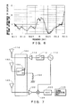
- FIG. 2 is a diagram showing an exemplary configuration of the basic embodiment of the present disclosure.
- FIG. 3 is a cross sectional view showing a state where the substrate shown in FIG. 2 is accommodated in a radome.
- FIG. 4 is a diagram for explaining an operation of a basic embodiment of the present disclosure.
- FIG. 5 is a graph showing an example of an isolation result of the transmitting antenna and the receiving antenna.
- FIG. 6 is a graph showing an exemplary improvement in the isolation effect by the dummy antenna.
- FIG. 7 is a block diagram showing an exemplary configuration of a first embodiment of the present disclosure.
- FIG. 8 is a diagram for explaining functions of the dummy antenna of the first embodiment.
- FIG. 9 is a block diagram showing an exemplary configuration of a second embodiment of the present disclosure.
- FIG. 10 is a diagram for explaining functions of the dummy antenna of the second embodiment.
- FIG. 11 is a block diagram showing an exemplary configuration of a third embodiment of the present disclosure.
- FIG. 12 is a diagram for explaining functions of the dummy antenna of the third embodiment.
- FIG. 13 is a block diagram showing an exemplary configuration of a fourth embodiment of the present disclosure.
- FIG. 14 is a diagram showing a relationship between a transmission signal, reflected waves from a bumper, and a reflected wave from an object in the fourth embodiment.
- FIG. 15 is a diagram for explaining functions of the dummy antenna of the fourth embodiment.
- FIG. 16 shows an example of a substrate of a radar of the related art.
- FIG. 17 is a diagram showing a state in which the substrate shown in FIG. 16 is accommodated in a radome and stored at a back side of the bumper.
- FIG. 18 is a diagram showing a relationship between a transmission signal, reflected waves from a bumper and a reflected wave from an object.
- FIG. 1 is a block diagram schematically showing a circuit of the radar device.
- the radar device has a circuit formed therein that includes a transmitting antenna 110 , a receiving antenna 120 , a dummy antenna 150 , and a circuit selecting section 160 .
- An oscillation section 112 , a switch 113 and an amplifier 114 are connected to the transmitting antenna 110 .
- the oscillation section 112 generates and outputs a signal in a high frequency band.
- the switch 113 switches the signal outputted from the oscillation section 112 in response to the control of a control unit, not shown, to generate a pulse signal and supply it to the amplifier 114 .
- the amplifier 114 amplifies an electric power of the signal supplied from the switch 113 and supplies it to the transmitting antenna 110 .
- the transmitting antenna 110 sends out the signal supplied from the amplifier 114 as a radio wave.
- An amplifier 122 , a mixer 123 , an ADC (Analog to Digital Converter) 124 and a signal processing unit 125 are connected to the receiving antenna 120 .
- the amplifier 122 amplifies and outputs an electric signal corresponding to the radio wave captured by the receiving antenna 120 .
- the mixer 123 down-converts the signal outputted from the amplifier 122 by a signal of a high frequency band supplied from the oscillation section 112 .
- the ADC 124 converts and outputs an electric signal (analog signal) outputted from the mixer 123 into a corresponding digital signal.
- the signal processing unit 125 detects a position, a distance, a velocity, etc., of the object by performing a predetermined process on the digital signal outputted from the ADC 124 and outputs them to a higher level device, not shown. In a case where it is driven at a low frequency, it is not necessary to provide the mixer 123 .
- a resistance element 152 is connected to the dummy antenna 150 .
- the resistance element 152 is a resistance element for matched termination of the dummy antenna 150 .
- the resistance element 152 has a resistance value which is the same as a characteristic impedance of the dummy antenna 150 , and one terminal thereof is connected to the dummy antenna 150 and the other terminal thereof is grounded.
- one terminal of the resistance element 152 may be connected to each of the antenna units and the other terminal of the resistance element 152 may be grounded.
- the dummy antenna 150 is configured to be selectable as an antenna having another function by a circuit selecting unit 160 .
- the circuit selecting unit 160 is a function part with which the configuration of the antenna circuit of the radar device is selectable depending on the control of a control unit, not shown, and has a function of selecting the dummy antenna 150 to be connected to the amplifier 114 similarly to the transmitting antenna 110 or to be connected to the amplifier 122 similarly to the receiving antenna 120 .
- the dummy antenna 150 implements the function of capturing and attenuating the reflected wave.
- the dummy antenna 150 functions as a noise attenuating antenna that captures and attenuates a noise that affects a received signal, which is a reflected wave from an object.
- the circuit selecting unit 160 selects a circuit such that the dummy antenna 150 is connected to the amplifier 114 , the dummy antenna 150 functions as a transmitting antenna that sends out an electric signal outputted from the oscillation section 112 .
- the circuit selecting unit 160 selects a circuit such that the dummy antenna 150 is connected to the amplifier 122 , the dummy antenna 150 functions as a receiving antenna that captures and outputs a radio wave to the mixer 123 .
- the circuit selecting unit 160 need not possess all of the functions described above.
- the circuit selecting unit 160 may have a configuration that has a function of selecting a circuit such that the dummy antenna 150 functions as the transmitting antenna 110 but does not have a function of selecting the circuit such that the dummy antenna 150 functions as the receiving antenna 120 .
- the circuit selecting unit 160 may have a configuration that has a function of selecting a circuit such that the dummy antenna 150 functions as the receiving antenna 120 but does not have a function of selecting the circuit such that the dummy antenna 150 functions as the transmitting antenna 110 .
- FIG. 2 is a plan view showing a surface of the substrate 10 of the radar device 1 of a basic embodiment of the present disclosure on which antennas are formed.
- the transmitting antenna 110 is formed on the right-hand side (the right-hand side in FIG. 2 ) of the substrate 10 with a plurality of (in FIG. 2 , four) antenna units 111 being arrayed.
- the receiving antenna 120 is formed on the left-hand side (the left-hand side in FIG. 2 ) of the substrate 10 with a plurality of (in FIG. 2 , eight) antenna units 121 being arrayed.
- the dummy antenna 150 is formed at the center (at the center in FIG. 2 ) of the substrate 10 with a plurality of (in FIG.
- the transmitting antennas 110 has four units
- the receiving antennas 120 has eight units
- the dummy antennas 150 has eight units, but any other combination of numbers of units may be used.
- the geometry of the antenna is not limited to the geometry shown in FIG. 2 and antennas having other geometries may be used.
- those constituent elements other than the antenna circuit (the transmitting antenna 110 , the receiving antenna 120 , and the dummy antenna 150 ) shown in FIG. 2 may be provided outside an antenna mounting region of the substrate 10 , may be provided on a back surface of the substrate 10 , or may be provided on a circuit board (not shown) that is different from the substrate 10 .
- FIG. 3 is a cross sectional view showing a state where the substrate 10 shown in FIG. 2 is accommodated in a radome 20 .
- the radome 20 is made of a resin having radio wave permeability and has a box shape.
- the substrate 10 is arranged in such a manner that a surface on which antennas are formed faces inwardly of the radome 20 .
- a high frequency band refers to a band ranging from a quasi-millimeter wave to a millimeter wave.
- a resonant length L of the antenna is generally represented by Equation 1 or Equation 2 described below depending on the type of the antenna.
- Equation 3 An element pitch W when arranging the antenna units in an array is generally represented by following Equation 3. W ⁇ [Equation 3]
- ⁇ r is a relative dielectric constant of the substrate and ⁇ is a wavelength of a signal in the high frequency band.
- a band of the high frequency signal sent out from the transmitting antenna 110 ranges from a quasi-millimeter wave to a millimeter wave
- antenna areas of the transmitting antenna 110 and the receiving antenna 120 , as well as the dummy antenna 150 can be reduced.
- a band of the high frequency signal is 24.15 GHz band, which is a quasi-millimeter wave band
- a relative dielectric constant of the substrate 10 is 4
- the substrate 10 of the radar device 1 of the basic embodiment of FIG. 2 may be have a size of around 75 mm ⁇ 90 mm in accordance with the above equations.
- FIG. 4 is a diagram for explaining an operation of the basic embodiment of the present disclosure.
- a radio wave transmitted from the transmitting antenna 110 is reflected by the bumper B and is incident on the dummy antenna 150 , as indicated by a broken line in FIG. 4 .
- the dummy antenna 150 is matched-terminated as described above, the radio wave which is incident on the dummy antenna 150 is converted into heat by the resistance element 152 and thus most of the incident radio wave is not reflected.
- the radio wave reflected by the bumper B is almost not incident on the receiving antenna 120 , the reflected wave from the bumper B shown in FIG. 18 is drastically attenuated, and, a false detection by the radar device 1 can be prevented.
- the matched-terminated dummy antenna 150 is provided on the substrate 10 , the radio wave reflected by the bumper B can be prevented from being incident on the receiving antenna 120 . Therefore, a false detection due to the reflected wave from the bumper B can be prevented. Also, in the example of FIG. 2 , since the dummy antenna 150 is provided between the transmitting antenna 110 and the receiving antenna 120 , the transmitting antenna 110 and the receiving antenna 120 are separated by the dummy antenna 150 that captures and attenuates the reflected wave from the bumper B that becomes a noise, and an influence of the reflected wave on the received wave can be reduced.
- the dummy antenna 150 With the function of the dummy antenna 150 being selectable in such a manner that the dummy antenna 150 functions as another antenna other than the noise attenuating antenna, an effective use of an antenna can be promoted while reducing an influence of a structure, such as a bumper, on the transmission signal and the received signal.
- FIG. 5 is a graph showing a relationship between an isolation, which represents an amount of coupling between the transmitting antenna 110 and the receiving antenna 120 in the radar device 1 , and a band of a signal that is sent out.
- f 0 indicates a frequency of the high frequency signal, which is 24.15 GHz here.
- FIG. 5 shows an isolation result (solid line) for a case where the bumper B does not exist and the dummy antenna 150 is not provided, an isolation result (dash-dot line) for a case where the bumper B exists and the dummy antenna 150 is not provided, and an isolation result (broken line) for a case where the bumper B exists and the dummy antenna 150 is provided.
- an isolation between the transmitting antenna and the receiving antenna is used as an index indicating an influence of the bumper on the received signal.
- the dummy antenna 150 that is described with reference to FIG. 5 is assumed to be a noise attenuating antenna. That is, in an electrical configuration in the radar device 1 shown in FIG. 1 , the dummy antenna 150 that is described with reference to FIG. 5 is connected to the resistance element 152 by the circuit selecting unit 160 , at an incident timing of the reflected wave from the bumper B.
- isolation is degraded by approximately 15 dB at a maximum due to an influence of the reflected wave produced by an existence of the bumper B. Further, in the presence of the bumper B, it can be seen that isolation is improved by providing the dummy antenna 150 .
- FIG. 6 shows an amount of improvement in an isolation result for a case where the dummy antenna 150 is provided in a state where the bumper B exists.
- FIG. 6 is a graph that has a horizontal axis representing the frequency of an emitted signal and a vertical axis representing an amount of improvement in the isolation result. As shown in FIG. 6 , it can be seen that, by providing the dummy antenna 150 , the isolation result is improved by approximately 12 dB at a maximum.
- FIG. 7 is a block diagram showing an example of the electrical configuration of the first embodiment. Note that, in this figure, parts corresponding to those shown in FIG. 1 are accompanied by the same reference numerals and descriptions thereof are omitted. As compared to FIG. 1 , the first embodiment shown in FIG. 7 has a switch 153 as the circuit selecting unit 160 .
- the switch 153 has a terminal connected to the dummy antenna 150 and two selective terminals, in which one of the selective terminals is connected to an output terminal of the amplifier 114 and the other selective terminal is connected to one of the terminals of the resistance element 152 .
- the switch 153 is controlled to select an output terminal of the amplifier 114 during a period in which the high frequency signal is transmitted from the transmitting antenna 110 , and to select a terminal of the resistance element 152 as the transmission is terminated.
- the resistance element 152 is a termination resistance and has the same resistance value as a characteristic impedance of the dummy antenna 150 .
- FIG. 8 is a diagram showing a function of the dummy antenna 150 of the first embodiment of the radar device 1 .
- FIG. 8 shows, at an upper part, a time-series relationship between a transmission signal, reflected waves R 1 to R 4 from the bumper B, and a received signal which is a reflected wave from an object, that are transmitted and received in the first embodiment of the radar device 1 similarly to FIG. 18 , and shows, at a lower part, functions of the dummy antenna 150 at each timing.
- the dummy antenna 150 is connected to the amplifier 114 by the switch 153 .
- a signal outputted from the amplifier 114 is supplied to the transmitting antenna 110 and also supplied to the dummy antenna 150 via the switch 153 , and as a result, the transmission signal is transmitted not only from the transmitting antenna 110 but also from the dummy antenna 150 .
- the dummy antenna 150 is connected to the resistance element 152 by the switch 153 .
- the reflected waves R 1 to R 4 from the bumper B that have been incident on the dummy antenna 150 are supplied to the resistance element 152 and converted into heat there.
- the radio wave reflected by the bumper B is attenuated, a false detection of the reflected wave from the bumper B can be prevented.
- the dummy antenna 150 is connected to the resistance element 152 in a period T 3 as well. Since the reflected wave from the bumper B is attenuated also in the period T 3 , an influence on the received signal which is the reflected wave from the object can be reduced.
- the dummy antenna 150 is made to function as a transmitting antenna in the period T 1 and made to function as a noise attenuating antenna that attenuates the reflected wave from the bumper B by being matched-terminated in the periods T 2 and T 3 .
- transmission efficiency can be improved by increasing an area of the transmitting antenna while reducing an influence of reflected waves R 1 to R 4 from the bumper B.
- the dummy antenna 150 is connected to the resistance element 152 throughout the periods T 2 to T 3 , and when the first reflected wave R 1 from the bumper B is attenuated by the dummy antenna 150 , subsequent reflected waves R 2 to R 4 are attenuated in comparison to the example shown in FIG. 18 . Therefore, the function as a noise attenuating antenna is sufficiently achieved.
- the period T 3 can be made to start earlier by making the period T 2 shorter as compared to FIG. 18 .
- the received signal which is a reflected wave from the object at a shorter distance, can be received without being influenced by a noise which is the reflected wave from the bumper B.
- FIG. 9 is a block diagram showing an example of the electrical configuration of the second embodiment. Note that, in this figure, parts corresponding to those shown in FIG. 1 are accompanied by the same reference numerals and descriptions thereof are omitted. As compared to FIG. 1 , the second embodiment shown in FIG. 9 has a switch 153 as the circuit selecting unit 160 .
- the switch 153 has a terminal connected to the dummy antenna 150 and two selective terminals, in which one of the selective terminals is connected to a terminal of the resistance element 152 and the other selective terminal is connected to an input terminal of the amplifier 122 .
- the switch 153 is controlled by a control unit, not shown, to select an output of the resistance element 152 when a reflected wave from the bumper B is incoming and to select an input terminal of the amplifier 122 when a reflected wave from the object is incoming.
- FIG. 10 is a diagram showing a function of the dummy antenna 150 of the second embodiment of the radar device 1 .
- FIG. 10 shows, at an upper part, a time series relationship between the transmission signal, the reflected waves R 1 to R 4 from the bumper B, and a reflected wave (received signal) from an object, that are transmitted and received in the second embodiment of the radar device 1 similarly to FIG. 18 , and shows, at a lower part, functions of the dummy antenna 150 at each timing.
- the dummy antenna 150 is connected to the resistance element 152 by the switch 153 in the periods T 1 and T 2 in FIG. 10 .
- the reflected waves R 1 to R 4 from the bumper B that are incident on the dummy antenna 150 are supplied to the resistance element 152 , and are converted into heat there.
- the radio wave reflected by the bumper B is attenuated, the reflected wave from the bumper B can be prevented from being falsely detected as the received wave.
- the dummy antenna 150 is connected to the amplifier 122 by the switch 153 . Thereby, not only the reflected wave from the object that is incident on the receiving antenna 120 but also the reflected wave from the object that is incident on the dummy antenna 150 is supplied to the amplifier 122 . As a result, by increasing an area of the receiving antenna to increases a reception gain, a detecting distance can be increased.
- the dummy antenna 150 is connected to the resistance element 152 also in the period T 1 , during which the transmission signal is transmitted from the transmitting antenna 110 .
- the reflected wave from the bumper B is also attenuated in the period T 1 , for example when a cycle of T 1 to T 3 in FIG. 10 is repeated, a reflected wave produced by a reflection of the transmission signal, which was transmitted in the previous cycle, on the bumper B can be attenuated and an influence on the received signal can be reduced.
- the dummy antenna 150 is matched-terminated in periods T 1 and T 2 to function as a noise attenuating antenna that attenuates the reflected wave from the bumper B, and to function as a receiving antenna in the period T 3 .
- the switch 153 is connected to the resistance element 152 throughout the periods T 1 to T 2 , and when the first reflected wave R 1 from the bumper B is attenuated by the dummy antenna 150 , subsequent reflected waves R 2 to R 4 are attenuated in comparison to the example shown in FIG. 18 . Therefore, the function as a noise attenuating antenna is sufficiently achieved.
- the period T 3 can be started earlier by making the period T 2 shorter in comparison to FIG. 18 .
- the received signal which is the reflected wave from the object at a shorter distance can be received without being influenced by the reflected wave.
- FIG. 11 is a block diagram showing an example of the electrical configuration of the third embodiment. Note that, in this figure, parts corresponding to those shown in FIG. 1 are accompanied by the same reference numerals and the descriptions thereof are omitted. As compared to FIG. 1 , the third embodiment shown in FIG. 11 has a switch 154 as the circuit selecting unit 160 .
- the switch 154 has a terminal connected to the dummy antenna 150 and three selective terminals, in which one of the selective terminals arranged upper most in the figure is connected to an output terminal of the amplifier 114 , a middle selective terminal is connected to the resistance element 152 , and a selective terminal arranged lower most in the figure is connected to an input terminal of the amplifier 122 .
- FIG. 12 is a diagram showing a function of the dummy antenna 150 of the third embodiment of the radar device 1 .
- FIG. 12 shows, at an upper part, a time series relationship between a transmission signal, reflected waves R 1 to R 4 from the bumper B, and a reflected wave (received signal) from an object that are transmitted and received in the third embodiment of the radar device 1 similarly to FIG. 18 , and, at a lower part, functions of the dummy antenna 150 at each timing.
- the dummy antenna 150 is connected to the amplifier 114 by the switch 154 in the period T 1 in FIG. 12 . Thereby, the transmission signal is transmitted from the dummy antenna 150 similarly to the transmitting antenna 110 .
- the dummy antenna 150 is connected to the resistance element 152 by the switch 154 . Thereby, the reflected waves R 1 to R 4 from the bumper B that are incident on the dummy antenna 150 are converted into heat by the resistance element 152 and attenuated.
- the dummy antenna 150 is connected to the amplifier 122 by the switch 154 . Thereby, the received signal that is incident on the dummy antenna 150 is, similarly to the signal received by the receiving antenna 120 , outputted to the amplifier 122 .
- the dummy antenna 150 functions as a transmitting antenna in the period T 1 , functions as a noise attenuating antenna that attenuates the reflected wave from the bumper B by being matched-terminated in the period T 2 , and functions as a receiving antenna in the period T 3 .
- transmission efficiency is improved by increasing an area of the transmitting antenna when transmitting radio waves, an influence of the reflected waves is suppressed by converting the incoming reflected waves into heat to attenuate the reflected wave in a period during which the reflected waves R 1 to R 4 from the bumper B are incoming, and a detection distance can be increased by increasing an area of the receiving antenna to increase the reception gain when receiving the received signal.
- the dummy antenna 150 is connected to the resistance element 152 throughout the period T 2 , and when the first reflected wave R 1 from the bumper B is attenuated by the dummy antenna 150 , subsequent reflected waves R 2 to R 4 are attenuated in comparison to the example shown in FIG. 18 . Therefore, the function as a noise attenuating antenna is sufficiently achieved.
- the period T 3 can be made to start earlier by making the period T 2 shorter as compared to FIG. 18 .
- the received signal which is the reflected wave from the object at a shorter distance can be received without being influenced by a noise which is the reflected wave from the bumper B.
- FIG. 13 is a block diagram showing an example of the electrical configuration of the fourth embodiment. Note that, in this figure, parts corresponding to those shown in FIG. 1 are accompanied by the same reference numerals and descriptions thereof are omitted. As compared to FIG. 1 , the fourth embodiment shown in FIG. 13 has a configuration that has a coupler 115 , a resistance element 152 a , an attenuator 155 and a phase shifter 156 as the circuit selecting unit 160 . The remaining configuration is similar to the case of FIG. 1 .
- the coupler 115 distributes and outputs a part of the signal outputted from the amplifier 114 to the attenuator 155 side.
- the resistance element 152 a terminates the coupler 115 .
- the attenuator 155 attenuates and outputs the signal outputted from the coupler 115 by a predetermined amount.
- the phase shifter 156 shifts and outputs a phase of the signal outputted from the attenuator 155 by a predetermined amount.
- the dummy antenna 150 transmits the signal outputted from the phase shifter 156 as a radio wave for cancelling out the reflected wave from the bumper B (hereinafter, referred to as a cancellation signal C).
- the fourth embodiment is a variant configuration example in which, in a circuit structure of the basic embodiment of the radar device 1 of the present disclosure shown in FIG. 1 , the resistance element 152 is replaced with the coupler 115 , the resistance element 152 a and the attenuator 155 and the phase shifter 156 .
- FIG. 14 is a diagram showing signals that are transmitted and received in the fourth embodiment of the radar device 1 , and specifically showing a relationship between the transmission signal, the reflected waves from the bumper, and the reflected wave (received signal) from an object.
- FIG. 11 shows, at an upper part, amplitude and time of each of a transmission signal from the radar device 1 , reflected waves from the bumper B, and a reflected wave from an object similarly to FIG. 14 , and, at a lower part, amplitude and time of a cancellation signal C transmitted from the dummy antenna 150 of the fourth embodiment.
- the transmission signal is transmitted from the transmitting antenna 110 and, in the subsequent period T 2 , the reflected wave from the bumper B is received several times (in FIG. 14 , four times) while being attenuated.
- the reflected wave from an object e.g., another vehicle is received in the subsequent period T 3 .
- the cancellation signal C which is a radio wave for cancelling out the reflected wave R 1 from the bumper B, is transmitted from the dummy antenna 150 .
- a cancellation signal C having the same intensity as the reflected wave R 1 and a phase which is 180 degrees out of phase is transmitted from the dummy antenna 150 and cancels out the reflected wave R 1 .
- the fourth embodiment of the radar device 1 most of the signals outputted from the amplifier 114 is transmitted via the transmitting antenna 110 in the period T 1 .
- a part of the signal outputted from the amplifier 114 is distributed by the coupler 115 and is supplied to the attenuator 155 .
- the attenuator 155 After attenuating the signal outputted from the coupler 115 by a predetermined amount, the attenuator 155 outputs it to the phase shifter 156 .
- the inputted signal is phase shifted (delayed) and outputted.
- the signal outputted from the phase shifter 156 is transmitted as a cancellation signal C via the dummy antenna 150 .
- the cancellation signal C transmitted from the dummy antenna 150 is adjusted by the attenuator 155 in such a manner that it has the same amplitude as the first reflected wave R 1 from the bumper B, and adjusted by the phase shifter 156 in such a manner that it is phase shifted by 180 degrees and emitted at a timing when the reflected wave R 1 is incident on the dummy antenna 150 .
- the reflected wave R 1 is cancelled out.
- the reflected waves R 1 to R 4 from the bumper in the period T 2 are attenuated.
- an influence of the reflected wave can be decreased, since an output signal from the amplifier 114 is partly distributed by the coupler 115 and attenuated by the attenuator 155 and thereafter phase shifted by the phase shifter 156 , outputted from the dummy antenna 150 and attenuated by cancelling out the reflected wave.
- the fourth embodiment may also be configured in such a manner that a destination of connection of the dummy antenna 150 can be changed using the circuit selecting unit 160 .
- one of the selective terminals of a switch connected to the dummy antenna 150 may be connected to an output terminal of the phase shifter 156 and the other selective terminal may be connected to an input terminal of the amplifier 122 .
- the reflected wave from the bumper B can be attenuated by selecting a terminal of the switch on the phase shifter 156 side to cause the cancellation signal C to be emitted from the dummy antenna 150 .
- the dummy antenna 150 can be made to function as a receiving antenna to thereby increase an area of the receiving antenna and to increase a reception gain.
- One of the selective terminals of the switch connected to the dummy antenna 150 may be connected to an output terminal of the phase shifter 156 , and the other selective terminal may be connected to an output terminal of the coupler 115 on the transmitting antenna 110 side.
- One of the selective terminals of the switch connected to the dummy antenna 150 may be connected to an output terminal of phase shifter 156 , and the other selective terminal may be connected to the resistance element 152 for matched termination of the dummy antenna 150 shown in FIG. 1 or the like.
- the dummy antenna 150 may function as an antenna emitting the cancellation signal C during a part of the period T 2 in FIG. 14 only (e.g., a timing when the first reflected wave R 1 from the bumper B is incoming) and, in the remaining period, may function as a noise attenuating antenna that captures and attenuates the reflected wave.
- an influence of the reflected wave from the bumper B can be further reduced.
- the dummy antenna 150 functions as a transmitting antenna in the period T 1 , functions as an antenna that transmits a cancellation signal C at a timing in the period T 2 when the first reflected wave R 1 from the bumper B is incoming, functions as a noise attenuating antenna that captures and attenuates the reflected wave in the remaining period of the period T 2 , and functions as the receiving antenna in the period T 3 .
- the period T 3 can be made to start earlier by shortening the period T 2 as compared to FIG. 18 .
- the receiving signal which is the reflected wave from the object at a shorter distance can be received without being influenced by the noise which is the reflected wave from the bumper B.
- the cancellation signal C transmitted from the dummy antenna 150 does not need to be intended for cancelling out the first reflected wave R 1 from the bumper B, and may be adjusted to cancel out other reflected waves (e.g., reflected waves R 2 to R 4 ).
- the dummy antenna 150 may be configured to transmit, at the timing when the reflected wave R 2 is incident on the dummy antenna 150 , a cancellation signal C which is adjusted by the attenuator 155 and the phase shifter 156 such that it has the same amplitude as the reflected wave R 2 and has a phase that differs by 180 degrees.
- each of the aforementioned embodiments is given by way of example, and various variant embodiments exist.
- the geometry, the number of units and the arrangement of the transmitting antenna 110 , the receiving antenna 120 and the dummy antenna 150 shown in FIG. 2 are given by way of example, and other configuration is also conceivable.
- the transmitting antenna, the receiving antenna and the dummy antenna need not be formed separate, and all of them may be formed integral or two types among them may be formed integral.
- the structure of the antenna itself need not be formed on a printed circuit board, but may be configured as various antennas including a horn antenna.
- the arrangement of the transmitting antenna, the dummy antenna, and the receiving antenna may be interchanged.
- the dummy antenna may be arranged around the transmitting antenna and the receiving antenna. Each antenna need not be arranged on the same plane.
- the position where the dummy antenna is arranged not limited thereto, and for example, the configuration may be such that the dummy antenna is arranged on a structure such as a bumper or a radome.
- a switch used for selecting between the dummy antenna and the receiving and transmitting antennas may be configured to be switched by a machine type switch or an electronic type switch.
- the bumper B was described as an example of the member by which the transmitting antenna 110 is reflected, but the present disclosure is also applicable to a case in which the radio wave is reflected by a member other than the bumper (e.g., an emblem). That is to say, for example, in the present disclosure, “a structure constantly arranged on a transmission path of the high frequency signal” is not limited to the bumper B, and may also include, for example, an emblem, a radome constituting the radar device 1 or the like.
- FIGS. 11 and 14 a case in which there are four reflected waves from the bumper B was shown by way of example, but the number of reflected waves may be other than this ( 1 to 3 waves or five or more waves). Also, in FIGS. 11 and 14 , a case in which the reflected wave from the bumper B and the reflected wave from an object are not superposed was explained by way of example, but the present disclosure is also applicable to a case where they are superposed.
Landscapes
- Engineering & Computer Science (AREA)
- Remote Sensing (AREA)
- Radar, Positioning & Navigation (AREA)
- Physics & Mathematics (AREA)
- Computer Networks & Wireless Communication (AREA)
- General Physics & Mathematics (AREA)
- Electromagnetism (AREA)
- Radar Systems Or Details Thereof (AREA)
- Variable-Direction Aerials And Aerial Arrays (AREA)
- Details Of Aerials (AREA)
Applications Claiming Priority (1)
| Application Number | Priority Date | Filing Date | Title |
|---|---|---|---|
| PCT/JP2013/062654 WO2014178125A1 (ja) | 2013-04-30 | 2013-04-30 | レーダ装置 |
Related Parent Applications (1)
| Application Number | Title | Priority Date | Filing Date |
|---|---|---|---|
| PCT/JP2013/062654 Continuation WO2014178125A1 (ja) | 2013-04-30 | 2013-04-30 | レーダ装置 |
Publications (2)
| Publication Number | Publication Date |
|---|---|
| US20150378006A1 US20150378006A1 (en) | 2015-12-31 |
| US9423491B2 true US9423491B2 (en) | 2016-08-23 |
Family
ID=50792162
Family Applications (1)
| Application Number | Title | Priority Date | Filing Date |
|---|---|---|---|
| US14/844,636 Active US9423491B2 (en) | 2013-04-30 | 2015-09-03 | Radar device |
Country Status (5)
| Country | Link |
|---|---|
| US (1) | US9423491B2 (tr) |
| EP (1) | EP2993485A4 (tr) |
| JP (1) | JP5485477B1 (tr) |
| CN (1) | CN104321663B (tr) |
| WO (1) | WO2014178125A1 (tr) |
Cited By (1)
| Publication number | Priority date | Publication date | Assignee | Title |
|---|---|---|---|---|
| US20220404463A1 (en) * | 2020-02-26 | 2022-12-22 | Huawei Technologies Co., Ltd. | Signal receiving method and device, medium, and radar system |
Families Citing this family (14)
| Publication number | Priority date | Publication date | Assignee | Title |
|---|---|---|---|---|
| DE102013220259A1 (de) * | 2013-10-08 | 2015-04-09 | Robert Bosch Gmbh | Radarsensor mit Radom |
| EP3264530B1 (en) * | 2015-02-27 | 2022-02-09 | Furukawa Electric Co., Ltd. | Antenna apparatus |
| JP6464124B2 (ja) * | 2016-09-08 | 2019-02-06 | 株式会社Soken | アンテナ装置 |
| JP6510394B2 (ja) * | 2015-12-15 | 2019-05-08 | 株式会社Soken | アンテナ装置 |
| US11575196B2 (en) | 2015-12-15 | 2023-02-07 | Denso Corporation | Antenna device |
| CN107181063A (zh) * | 2016-03-11 | 2017-09-19 | 华为技术有限公司 | 一种天线系统和通信设备 |
| JP6499116B2 (ja) | 2016-04-06 | 2019-04-10 | 株式会社Soken | アンテナ装置 |
| US10594019B2 (en) | 2016-12-03 | 2020-03-17 | International Business Machines Corporation | Wireless communications package with integrated antenna array |
| US10498415B2 (en) * | 2016-12-20 | 2019-12-03 | Raytheon Company | Systems and methods for a multi-mode active electronically scanned array |
| CN108258396B (zh) * | 2016-12-28 | 2019-12-31 | 中国移动通信集团公司 | 一种天线及通信终端 |
| IL271269A (en) * | 2019-12-09 | 2021-06-30 | Arbe Robotics Ltd | Radom for a planar antenna for car radar |
| CN111208505B (zh) * | 2020-01-15 | 2022-01-21 | 中国人民解放军战略支援部队信息工程大学 | 基于多目标跟踪的分布式mimo雷达最少阵元快速提取方法 |
| DE112021005328T5 (de) * | 2020-12-07 | 2023-07-27 | Hitachi Astemo, Ltd. | Radarvorrichtung |
| TWI869759B (zh) * | 2023-01-13 | 2025-01-11 | 明基電通股份有限公司 | 無線簡報裝置 |
Citations (20)
| Publication number | Priority date | Publication date | Assignee | Title |
|---|---|---|---|---|
| JPH03148082A (ja) | 1989-11-06 | 1991-06-24 | Mitsubishi Electric Corp | レーダ装置 |
| JPH03226690A (ja) | 1990-02-01 | 1991-10-07 | Mitsubishi Electric Corp | ディジタルビームフォーミングアンテナ装置 |
| US5325099A (en) * | 1993-04-28 | 1994-06-28 | Itt Corporation | Modular solid-state radar transmitter apparatus and method for producing variable waveforms |
| JPH11330847A (ja) | 1998-05-18 | 1999-11-30 | Yokowo Co Ltd | アンテナ装置 |
| JP2001099912A (ja) | 1999-09-30 | 2001-04-13 | Matsushita Electric Works Ltd | 正常動作自己診断機能付センサ |
| US6384781B1 (en) * | 2001-04-26 | 2002-05-07 | Lockheed Martin Corporation | Method and apparatus for calibrating a remote system which employs coherent signals |
| US20020105456A1 (en) | 2001-02-08 | 2002-08-08 | Fujitsu Ten Limited | Method and device for aligning radar mount direction, and radar aligned by the method or device |
| JP2004093292A (ja) | 2002-08-30 | 2004-03-25 | Matsushita Electric Works Ltd | 障害物検知装置 |
| CN1696735A (zh) | 2001-02-08 | 2005-11-16 | 富士通天株式会社 | 雷达安装方向调整方法、调整装置及雷达装置 |
| JP2006317162A (ja) | 2005-05-10 | 2006-11-24 | Matsushita Electric Ind Co Ltd | レーダ装置 |
| JP2008249678A (ja) | 2007-03-02 | 2008-10-16 | Toyota Central R&D Labs Inc | レーダ装置の被覆部品及び貼着部品 |
| US20080252524A1 (en) * | 2007-02-09 | 2008-10-16 | University Of Southern California | Path-Sharing Transceiver Architecture for Antenna Arrays |
| JP2009109333A (ja) | 2007-10-30 | 2009-05-21 | Mitsubishi Electric Corp | アンテナ装置 |
| JP2010109890A (ja) | 2008-10-31 | 2010-05-13 | Mitsubishi Electric Corp | アンテナ装置 |
| JP2010197283A (ja) | 2009-02-26 | 2010-09-09 | Mitsubishi Electric Corp | レーダ装置 |
| JP2011193133A (ja) | 2010-03-12 | 2011-09-29 | Mitsubishi Electric Corp | アンテナ装置 |
| JP2011242170A (ja) | 2010-05-14 | 2011-12-01 | Fuji Heavy Ind Ltd | 車両用レーダ装置 |
| CN102792179A (zh) | 2010-03-30 | 2012-11-21 | 古河电气工业株式会社 | 车载脉冲雷达 |
| US20130050008A1 (en) * | 2011-08-30 | 2013-02-28 | Massachusetts Institute Of Technology | Mobile coherent change detection ground penetrating radar |
| DE102013000858A1 (de) | 2012-01-19 | 2013-07-25 | Mando Corporation | Radarvorrichtung und Antennenvorrichtung |
Family Cites Families (3)
| Publication number | Priority date | Publication date | Assignee | Title |
|---|---|---|---|---|
| US3568194A (en) * | 1967-10-11 | 1971-03-02 | Us Air Force | System for degrading radar return signals |
| US5153594A (en) * | 1973-04-16 | 1992-10-06 | Moffat William V | Electronic counter-measure system for aircraft |
| EP1556923B1 (en) * | 2002-10-24 | 2013-05-15 | TELEFONAKTIEBOLAGET LM ERICSSON (publ) | Dynamic antenna |
-
2013
- 2013-04-30 EP EP13883826.3A patent/EP2993485A4/en not_active Ceased
- 2013-04-30 WO PCT/JP2013/062654 patent/WO2014178125A1/ja not_active Ceased
- 2013-04-30 CN CN201380019433.5A patent/CN104321663B/zh active Active
- 2013-04-30 JP JP2013539470A patent/JP5485477B1/ja active Active
-
2015
- 2015-09-03 US US14/844,636 patent/US9423491B2/en active Active
Patent Citations (22)
| Publication number | Priority date | Publication date | Assignee | Title |
|---|---|---|---|---|
| JPH03148082A (ja) | 1989-11-06 | 1991-06-24 | Mitsubishi Electric Corp | レーダ装置 |
| JPH03226690A (ja) | 1990-02-01 | 1991-10-07 | Mitsubishi Electric Corp | ディジタルビームフォーミングアンテナ装置 |
| US5325099A (en) * | 1993-04-28 | 1994-06-28 | Itt Corporation | Modular solid-state radar transmitter apparatus and method for producing variable waveforms |
| JPH11330847A (ja) | 1998-05-18 | 1999-11-30 | Yokowo Co Ltd | アンテナ装置 |
| JP2001099912A (ja) | 1999-09-30 | 2001-04-13 | Matsushita Electric Works Ltd | 正常動作自己診断機能付センサ |
| US20020105456A1 (en) | 2001-02-08 | 2002-08-08 | Fujitsu Ten Limited | Method and device for aligning radar mount direction, and radar aligned by the method or device |
| CN1696735A (zh) | 2001-02-08 | 2005-11-16 | 富士通天株式会社 | 雷达安装方向调整方法、调整装置及雷达装置 |
| US6384781B1 (en) * | 2001-04-26 | 2002-05-07 | Lockheed Martin Corporation | Method and apparatus for calibrating a remote system which employs coherent signals |
| JP2004093292A (ja) | 2002-08-30 | 2004-03-25 | Matsushita Electric Works Ltd | 障害物検知装置 |
| JP2006317162A (ja) | 2005-05-10 | 2006-11-24 | Matsushita Electric Ind Co Ltd | レーダ装置 |
| US20080252524A1 (en) * | 2007-02-09 | 2008-10-16 | University Of Southern California | Path-Sharing Transceiver Architecture for Antenna Arrays |
| JP2008249678A (ja) | 2007-03-02 | 2008-10-16 | Toyota Central R&D Labs Inc | レーダ装置の被覆部品及び貼着部品 |
| JP2009109333A (ja) | 2007-10-30 | 2009-05-21 | Mitsubishi Electric Corp | アンテナ装置 |
| JP2010109890A (ja) | 2008-10-31 | 2010-05-13 | Mitsubishi Electric Corp | アンテナ装置 |
| JP2010197283A (ja) | 2009-02-26 | 2010-09-09 | Mitsubishi Electric Corp | レーダ装置 |
| JP2011193133A (ja) | 2010-03-12 | 2011-09-29 | Mitsubishi Electric Corp | アンテナ装置 |
| CN102792179A (zh) | 2010-03-30 | 2012-11-21 | 古河电气工业株式会社 | 车载脉冲雷达 |
| US20130002471A1 (en) | 2010-03-30 | 2013-01-03 | Furukawa Automotive Systems Inc. | In-vehicle pulse radar |
| JP2011242170A (ja) | 2010-05-14 | 2011-12-01 | Fuji Heavy Ind Ltd | 車両用レーダ装置 |
| US20130050008A1 (en) * | 2011-08-30 | 2013-02-28 | Massachusetts Institute Of Technology | Mobile coherent change detection ground penetrating radar |
| DE102013000858A1 (de) | 2012-01-19 | 2013-07-25 | Mando Corporation | Radarvorrichtung und Antennenvorrichtung |
| US20130187808A1 (en) * | 2012-01-19 | 2013-07-25 | Mando Corporation | Radar apparatus and antenna apparatus |
Non-Patent Citations (4)
| Title |
|---|
| English translation of the International Preliminary Report on Patentability (Chapter I) for PCT/JP2013/062654 dated Nov. 3, 2015. |
| English translation of the Written Opinion of the International Search Authority for PCT/JP2013/062654 dated May 28, 2013. |
| International Search Report and Written Opinion dated May 28, 2013 for PCT/JP2013/062654. |
| Office Action dated Oct. 26, 2015 from corresponding Chinese Application No. 201380019433.5. |
Cited By (2)
| Publication number | Priority date | Publication date | Assignee | Title |
|---|---|---|---|---|
| US20220404463A1 (en) * | 2020-02-26 | 2022-12-22 | Huawei Technologies Co., Ltd. | Signal receiving method and device, medium, and radar system |
| US12481021B2 (en) * | 2020-02-26 | 2025-11-25 | Shenzhen Yinwang Intelligent Technologies Co., Ltd. | Signal receiving method and device, medium, and radar system |
Also Published As
| Publication number | Publication date |
|---|---|
| EP2993485A1 (en) | 2016-03-09 |
| CN104321663B (zh) | 2016-07-06 |
| US20150378006A1 (en) | 2015-12-31 |
| JP5485477B1 (ja) | 2014-05-07 |
| JPWO2014178125A1 (ja) | 2017-02-23 |
| EP2993485A4 (en) | 2017-03-08 |
| WO2014178125A1 (ja) | 2014-11-06 |
| CN104321663A (zh) | 2015-01-28 |
Similar Documents
| Publication | Publication Date | Title |
|---|---|---|
| US9423491B2 (en) | Radar device | |
| US10684355B2 (en) | Radar module, and vehicle radar device comprising same | |
| US9880275B2 (en) | Radar for vehicle and method of operating the same | |
| US6288672B1 (en) | Holographic radar | |
| JP2779559B2 (ja) | レーダ装置 | |
| US6043772A (en) | Multi-beam automobile radar system | |
| US7439901B2 (en) | Active phased array antenna for aircraft surveillance systems | |
| KR101442475B1 (ko) | 레이더 장치 | |
| EP2045877A1 (en) | Radar system and method of digital beamforming | |
| US11223112B2 (en) | Inverted microstrip travelling wave patch array antenna system | |
| US9445535B2 (en) | High-frequency module | |
| WO2012128127A1 (ja) | 高周波通信装置 | |
| JP3565140B2 (ja) | アレーアンテナ装置 | |
| JP2014190720A (ja) | レーダ装置 | |
| KR100979284B1 (ko) | 레이더 송수신 시스템 | |
| US11942685B2 (en) | Communication device | |
| KR101990076B1 (ko) | 위상 배열 레이더 | |
| EP2919320A1 (en) | Rfid reader device and antenna device | |
| KR101912519B1 (ko) | 하이브리드 마이크로파 영상 시스템 및 이의 동작 방법 | |
| JP2013026817A (ja) | フェーズドアレーアンテナ | |
| JP2012047492A (ja) | フェーズドアレイアンテナ | |
| EP3735592B1 (en) | A radar device | |
| JP2011506988A (ja) | モノスタティックマルチビームレーダセンサ、ならびに方法 | |
| JP2008249498A (ja) | レーダ装置 | |
| JP4428968B2 (ja) | 半導体素子スイッチによる負荷変動の低減構造およびそれを有するレーダ送受信機 |
Legal Events
| Date | Code | Title | Description |
|---|---|---|---|
| AS | Assignment |
Owner name: FURUKAWA AUTOMOTIVE SYSTEMS INC., JAPAN Free format text: ASSIGNMENT OF ASSIGNORS INTEREST;ASSIGNORS:ISHIDA, YOSHIYUKI;MATSUSHIMA, SADAO;REEL/FRAME:036995/0111 Effective date: 20151015 Owner name: FURUKAWA ELECTRIC CO., LTD., JAPAN Free format text: ASSIGNMENT OF ASSIGNORS INTEREST;ASSIGNORS:ISHIDA, YOSHIYUKI;MATSUSHIMA, SADAO;REEL/FRAME:036995/0111 Effective date: 20151015 |
|
| STCF | Information on status: patent grant |
Free format text: PATENTED CASE |
|
| MAFP | Maintenance fee payment |
Free format text: PAYMENT OF MAINTENANCE FEE, 4TH YEAR, LARGE ENTITY (ORIGINAL EVENT CODE: M1551); ENTITY STATUS OF PATENT OWNER: LARGE ENTITY Year of fee payment: 4 |
|
| MAFP | Maintenance fee payment |
Free format text: PAYMENT OF MAINTENANCE FEE, 8TH YEAR, LARGE ENTITY (ORIGINAL EVENT CODE: M1552); ENTITY STATUS OF PATENT OWNER: LARGE ENTITY Year of fee payment: 8 |