US9318151B2 - Mobile terminal and method for controlling the same - Google Patents
Mobile terminal and method for controlling the same Download PDFInfo
- Publication number
- US9318151B2 US9318151B2 US13/208,271 US201113208271A US9318151B2 US 9318151 B2 US9318151 B2 US 9318151B2 US 201113208271 A US201113208271 A US 201113208271A US 9318151 B2 US9318151 B2 US 9318151B2
- Authority
- US
- United States
- Prior art keywords
- image
- mobile terminal
- preview image
- edited
- display
- Prior art date
- Legal status (The legal status is an assumption and is not a legal conclusion. Google has not performed a legal analysis and makes no representation as to the accuracy of the status listed.)
- Active, expires
Links
- 238000000034 method Methods 0.000 title claims abstract description 44
- 230000003190 augmentative effect Effects 0.000 claims abstract description 11
- 230000006870 function Effects 0.000 claims description 74
- 238000004891 communication Methods 0.000 claims description 33
- 230000004044 response Effects 0.000 claims description 17
- 230000008676 import Effects 0.000 claims 22
- 230000000694 effects Effects 0.000 description 21
- 230000008859 change Effects 0.000 description 12
- 230000005540 biological transmission Effects 0.000 description 7
- 238000010295 mobile communication Methods 0.000 description 7
- 230000005236 sound signal Effects 0.000 description 7
- 238000012545 processing Methods 0.000 description 6
- 238000005516 engineering process Methods 0.000 description 5
- 230000008569 process Effects 0.000 description 4
- 230000009471 action Effects 0.000 description 3
- 230000008901 benefit Effects 0.000 description 3
- 239000004973 liquid crystal related substance Substances 0.000 description 3
- 238000003909 pattern recognition Methods 0.000 description 3
- 230000009467 reduction Effects 0.000 description 3
- 230000004397 blinking Effects 0.000 description 2
- 230000003247 decreasing effect Effects 0.000 description 2
- 238000010586 diagram Methods 0.000 description 2
- 230000006872 improvement Effects 0.000 description 2
- 238000007726 management method Methods 0.000 description 2
- 230000004048 modification Effects 0.000 description 2
- 238000012986 modification Methods 0.000 description 2
- 229910001220 stainless steel Inorganic materials 0.000 description 2
- 239000010935 stainless steel Substances 0.000 description 2
- 230000003068 static effect Effects 0.000 description 2
- 239000010936 titanium Substances 0.000 description 2
- RTAQQCXQSZGOHL-UHFFFAOYSA-N Titanium Chemical compound [Ti] RTAQQCXQSZGOHL-UHFFFAOYSA-N 0.000 description 1
- 230000001133 acceleration Effects 0.000 description 1
- 238000003491 array Methods 0.000 description 1
- 230000001186 cumulative effect Effects 0.000 description 1
- 238000013500 data storage Methods 0.000 description 1
- 230000005684 electric field Effects 0.000 description 1
- 230000005672 electromagnetic field Effects 0.000 description 1
- 239000010408 film Substances 0.000 description 1
- 238000002347 injection Methods 0.000 description 1
- 239000007924 injection Substances 0.000 description 1
- 238000001746 injection moulding Methods 0.000 description 1
- 239000002184 metal Substances 0.000 description 1
- 229910052751 metal Inorganic materials 0.000 description 1
- 210000003205 muscle Anatomy 0.000 description 1
- 230000006855 networking Effects 0.000 description 1
- 230000003287 optical effect Effects 0.000 description 1
- 230000010355 oscillation Effects 0.000 description 1
- 229920003002 synthetic resin Polymers 0.000 description 1
- 239000000057 synthetic resin Substances 0.000 description 1
- 239000010409 thin film Substances 0.000 description 1
- 229910052719 titanium Inorganic materials 0.000 description 1
- 238000012546 transfer Methods 0.000 description 1
- 230000000007 visual effect Effects 0.000 description 1
Images


Classifications
-
- H—ELECTRICITY
- H04—ELECTRIC COMMUNICATION TECHNIQUE
- H04W—WIRELESS COMMUNICATION NETWORKS
- H04W88/00—Devices specially adapted for wireless communication networks, e.g. terminals, base stations or access point devices
- H04W88/02—Terminal devices
-
- G—PHYSICS
- G11—INFORMATION STORAGE
- G11B—INFORMATION STORAGE BASED ON RELATIVE MOVEMENT BETWEEN RECORD CARRIER AND TRANSDUCER
- G11B27/00—Editing; Indexing; Addressing; Timing or synchronising; Monitoring; Measuring tape travel
- G11B27/02—Editing, e.g. varying the order of information signals recorded on, or reproduced from, record carriers
- G11B27/031—Electronic editing of digitised analogue information signals, e.g. audio or video signals
- G11B27/034—Electronic editing of digitised analogue information signals, e.g. audio or video signals on discs
-
- G—PHYSICS
- G06—COMPUTING; CALCULATING OR COUNTING
- G06T—IMAGE DATA PROCESSING OR GENERATION, IN GENERAL
- G06T11/00—2D [Two Dimensional] image generation
- G06T11/60—Editing figures and text; Combining figures or text
-
- G—PHYSICS
- G11—INFORMATION STORAGE
- G11B—INFORMATION STORAGE BASED ON RELATIVE MOVEMENT BETWEEN RECORD CARRIER AND TRANSDUCER
- G11B27/00—Editing; Indexing; Addressing; Timing or synchronising; Monitoring; Measuring tape travel
- G11B27/10—Indexing; Addressing; Timing or synchronising; Measuring tape travel
- G11B27/102—Programmed access in sequence to addressed parts of tracks of operating record carriers
- G11B27/105—Programmed access in sequence to addressed parts of tracks of operating record carriers of operating discs
-
- G—PHYSICS
- G11—INFORMATION STORAGE
- G11B—INFORMATION STORAGE BASED ON RELATIVE MOVEMENT BETWEEN RECORD CARRIER AND TRANSDUCER
- G11B27/00—Editing; Indexing; Addressing; Timing or synchronising; Monitoring; Measuring tape travel
- G11B27/10—Indexing; Addressing; Timing or synchronising; Measuring tape travel
- G11B27/19—Indexing; Addressing; Timing or synchronising; Measuring tape travel by using information detectable on the record carrier
- G11B27/28—Indexing; Addressing; Timing or synchronising; Measuring tape travel by using information detectable on the record carrier by using information signals recorded by the same method as the main recording
- G11B27/32—Indexing; Addressing; Timing or synchronising; Measuring tape travel by using information detectable on the record carrier by using information signals recorded by the same method as the main recording on separate auxiliary tracks of the same or an auxiliary record carrier
- G11B27/322—Indexing; Addressing; Timing or synchronising; Measuring tape travel by using information detectable on the record carrier by using information signals recorded by the same method as the main recording on separate auxiliary tracks of the same or an auxiliary record carrier used signal is digitally coded
-
- G—PHYSICS
- G11—INFORMATION STORAGE
- G11B—INFORMATION STORAGE BASED ON RELATIVE MOVEMENT BETWEEN RECORD CARRIER AND TRANSDUCER
- G11B27/00—Editing; Indexing; Addressing; Timing or synchronising; Monitoring; Measuring tape travel
- G11B27/10—Indexing; Addressing; Timing or synchronising; Measuring tape travel
- G11B27/34—Indicating arrangements
-
- H—ELECTRICITY
- H04—ELECTRIC COMMUNICATION TECHNIQUE
- H04M—TELEPHONIC COMMUNICATION
- H04M1/00—Substation equipment, e.g. for use by subscribers
- H04M1/72—Mobile telephones; Cordless telephones, i.e. devices for establishing wireless links to base stations without route selection
- H04M1/724—User interfaces specially adapted for cordless or mobile telephones
-
- H—ELECTRICITY
- H04—ELECTRIC COMMUNICATION TECHNIQUE
- H04W—WIRELESS COMMUNICATION NETWORKS
- H04W4/00—Services specially adapted for wireless communication networks; Facilities therefor
- H04W4/02—Services making use of location information
- H04W4/023—Services making use of location information using mutual or relative location information between multiple location based services [LBS] targets or of distance thresholds
-
- H—ELECTRICITY
- H04—ELECTRIC COMMUNICATION TECHNIQUE
- H04W—WIRELESS COMMUNICATION NETWORKS
- H04W4/00—Services specially adapted for wireless communication networks; Facilities therefor
- H04W4/20—Services signaling; Auxiliary data signalling, i.e. transmitting data via a non-traffic channel
- H04W4/21—Services signaling; Auxiliary data signalling, i.e. transmitting data via a non-traffic channel for social networking applications
-
- H—ELECTRICITY
- H04—ELECTRIC COMMUNICATION TECHNIQUE
- H04M—TELEPHONIC COMMUNICATION
- H04M2201/00—Electronic components, circuits, software, systems or apparatus used in telephone systems
- H04M2201/42—Graphical user interfaces
Definitions
- the present invention relates to a mobile terminal, and more particularly, to a mobile terminal and a method of controlling the mobile terminal.
- a mobile terminal is a device that can be configured to perform various functions, such as data and voice communications, capturing still images and video via a camera, recording audio, playing music files and outputting music via a speaker system, and displaying images and video on a display. Some terminals include additional functionality to support game playing, while other terminals are also configured as multimedia players. More recently, mobile terminals have been configured to receive broadcast and multicast signals to permit viewing of content, such as videos and television programs.
- terminals can be classified as mobile terminals and stationary terminals. Furthermore, the mobile terminals can be classified as handheld terminals and vehicle mount terminals according to whether users can carry the terminals on their person.
- AR augmented reality
- the present invention is directed to a mobile terminal and a method for controlling the same, which substantially obviate one or more problems due to limitations and disadvantages of the related art.
- a method for controlling a mobile terminal includes displaying, on a display, a preview image input by a camera in an augmented reality (AR) mode.
- the method further includes displaying, on the display, AR data corresponding to at least one object in the preview image and providing a user interface for editing at least a portion of the preview image including the AR data in the AR mode in order to generate an edited preview image.
- AR augmented reality
- the method further includes storing the edited preview image in a memory. It is further contemplated that the method includes transmitting the stored edited preview image.
- the method further includes transmitting the edited preview image.
- the method further includes searching at least one stored edited preview image in the AR mode, and displaying AR data of the searched at least one stored edited preview image that corresponds to at least a same object in the preview image or a position of the preview image, where displaying the AR data is performed by either overlaying at least a portion of the searched at least one stored edited preview image on the preview image or displaying the searched at least one stored edited preview image.
- the method further includes, identifying an object in the preview image, determining whether the object in the preview image is the same as an object in a previously received edited preview image in the AR mode, and displaying AR data corresponding to the object in the previously received edited preview image on the object in the preview image based on the determination by either overlaying at least a portion of the previously received edited preview image on the preview image or displaying the previously received edited preview image.
- the method further includes editing the at least a portion of the preview image by changing an appearance of at least the AR data or the at least one object in response to input received via the user interface in accordance with at least one function. It is further contemplated that the at least one function is used to distinguish at least the AR data or the at least one object in the preview image.
- editing the at least a portion of the preview image includes zooming-in or zooming-out of the preview image in response to input received via the user interface such that the edited preview image is a zoomed-in or zoomed-out preview image and further includes storing the zoomed-in or zoomed-out preview image in a memory.
- the method further includes storing a value representing a magnification power of the zoomed-in or zoomed-out preview image and position information of the zoomed-in or zoomed-out preview image, and applying the value representing the magnification power to the preview image.
- editing the at least a portion of the preview image includes inputting a memo or scribble message on the preview image in response to the input received via the user interface and further includes storing the edited preview image including the memo or scribble message in a memory.
- the user interface provides a function for importing at least one image onto the preview image and merging the at least one image with the preview image in order to generate the edited preview image and further includes storing the edited preview image including the at least one image in a memory.
- importing the at least one image includes dragging and dropping the at least one image on a zone within the preview image where the at least one image is to be merged, or designating a zone within the preview image where the at least one image is to be merged.
- importing the at least one image includes designating a first zone within the at least one image, cropping the at least one image according to the first zone in order to generate at least one cropped image, and designating a second zone within the preview image where the at least one cropped image is to be merged.
- the user interface further provides a function for receiving a keyword for searching at least the memory or the Internet for at least one image that is related to the keyword.
- the user interface provides a function for linking information to the preview image and further includes storing the preview image that has been linked in a memory, the information related to the preview image.
- a method for controlling a mobile terminal includes receiving a transmission including an edited preview image that was previously generated by editing at least a portion of a preview image including augmented reality (AR) data in an AR mode, determining a current position of the mobile terminal, and displaying, on a display, the edited preview image when the current position of the mobile terminal is the same as a position corresponding to the edited preview image, where displaying the edited preview image is performed by either overlaying at least a portion of the edited preview image on a current preview image or displaying the entire edited preview image.
- AR augmented reality
- the transmission further includes the position corresponding to the edited preview image.
- the method further includes determining the position corresponding to the edited preview image by comparing the edited preview image to a current preview image input by a camera.
- a mobile terminal includes a display configured to display a preview image input by a camera in an augmented reality (AR) mode and to display AR data corresponding to at least one object in the preview image, and a controller configured to provide a user interface for editing at least a portion of the preview image including the AR data in the AR mode in order to generate an edited preview image.
- AR augmented reality
- controller is further configured to store the edited preview image in a memory. It is further contemplated that the controller is configured to transmit the stored edited preview image.
- controller is further configured to transmit the edited preview image.
- the controller is further configured to search at least one stored edited preview image in the AR mode, where the display is further configured to display AR data of the searched at least one stored edited preview image that corresponds to at least a same object in the preview image or a position of the preview image, and where the AR data of the searched edited preview image is displayed by either overlaying at least a portion of the searched at least one stored edited preview image on the preview image or displaying the searched at least one stored edited preview image.
- the controller is further configured to identify an object in the preview image and determine whether the object in the preview image is the same as an object in a previously received edited preview image in the AR mode, where the display is further configured to display AR data corresponding to the object in the previously received edited preview image on the object in the preview image based on the determination by either overlaying at least a portion of the previously received edited preview image on the preview image or displaying the previously received edited preview image.
- controller is further configured to edit the at least a portion of the preview image by changing an appearance of at least the AR data or the at least one object in response to input received via the user interface in accordance with at least one function.
- the at least one function is used to distinguish at least the AR data or the at least one object in the preview image.
- controller is further configured to edit the at least a portion of the preview image by zooming-in or zooming-out of the preview image in response to input received via the user interface such that the edited preview image is a zoomed-in or zoomed-out preview image, and store the zoomed-in or zoomed-out preview image in a memory.
- controller is further configured to store a value representing a magnification power of the zoomed-in or zoomed-out preview image and position information of the zoomed-in or zoomed-out preview image, and apply the value representing the magnification power to the preview image.
- controller is further configured to edit the at least a portion of the preview image by receiving a memo or scribble message input on the preview image via the user interface and store the edited preview image including the memo or scribble message in a memory.
- controller is further configured to provide the user interface having a function for importing at least one image onto the preview image and merging the at least one image with the preview image in order to generate the edited preview image. It is further contemplated that the controller is further configured to store the edited preview image including the at least one image in a memory.
- importing the at least one image includes dragging and dropping the at least one image on a zone within the preview image where the at least one image is to be merged or designating a zone within the preview image where the at least one image is to be merged.
- importing the at least one image includes designating a first zone within the at least one image, cropping the at least one image according to the first zone to generate at least one cropped image, and designating a second zone within the preview image where the at least one cropped image is to be merged.
- controller is further configured to provide the user interface further having a function for receiving a keyword for searching at least the memory or the Internet for the at least one image that is related to the keyword.
- controller is further configured to provide the user interface having a function for linking information to the preview image, the information related to the preview image, and store the preview image that has been linked in a memory.
- a mobile terminal includes a controller configured to receive a transmission comprising an edited preview image that was previously generated by editing at least a portion of a preview image including augmented reality (AR) data in an AR mode and determine a current position of the mobile terminal.
- the mobile terminal further includes a display configured to display the edited preview image when the current position of the mobile terminal is the same as a position corresponding to the edited preview image, where the edited preview image is displayed by either overlaying at least a portion of the edited preview image on a current preview image or displaying the entire edited preview image.
- AR augmented reality
- the transmission further includes the position corresponding to the edited preview image. It is further contemplated that the mobile terminal further includes a camera configured to generate the current preview image and wherein the controller is further configured to determine the position corresponding to the edited preview image by comparing the edited preview image to the current preview image.
- FIG. 1 illustrates a block diagram of a mobile terminal in accordance with one embodiment of the present invention.
- FIG. 2A is a front perspective view of the mobile terminal in accordance with one embodiment of the present invention.
- FIG. 2B is a rear perspective view of the mobile terminal in accordance with one embodiment of the present invention.
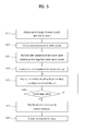
- FIG. 3 is a flow chart illustrating a method performed by the mobile terminal for editing a preview image in an augmented reality (AR) mode in accordance with one embodiment of the present invention.
- AR augmented reality
- FIGS. 4A through 8C are exemplary display screens of the display unit of the mobile terminal showing an operation for editing a preview image of the AR mode by changing a display style of a specific object or object information in accordance with various embodiments of the present invention.
- FIGS. 9A through 12B are exemplary display screens of the display unit of the mobile terminal showing an operation for distinguishing a specific object or object information within the preview image of the AR mode in accordance with various embodiments of the present invention.
- FIGS. 13A thorough 13 C are exemplary display screens of the display unit of the mobile terminal showing an operation for editing a preview image of the AR mode by inputting a memo message in accordance with one embodiment of the present invention.
- FIGS. 14A through 14C are exemplary display screens of the display unit of the mobile terminal showing an operation for editing a preview image of the AR mode by inputting a scribble message in accordance with one embodiment of the present invention.
- FIGS. 15A and 15B are exemplary display screens of the display unit of the mobile terminal showing an operation for editing a preview image of the AR mode by zooming in the preview image in accordance with one embodiment of the present invention.
- FIGS. 16A and 16B are exemplary display screens of the display unit of the mobile terminal showing an operation for editing a preview image of the AR mode by zooming out the preview image in accordance with one embodiment of the present invention.
- FIGS. 17A through 17D are exemplary display screens of the display unit of the mobile terminal showing an operation for editing a preview image of the AR mode by linking specific information to the preview image in accordance with one embodiment of the present invention.
- FIGS. 18A through 20C are exemplary display screens of the display unit of the mobile terminal showing various operations for editing a preview image of the AR mode by searching for an image associated with a search keyword and editing the preview image by merging the image with the preview image in accordance with various embodiments of the present invention.
- FIGS. 21A through 21C are exemplary display screens of the display unit of the mobile terminal showing an operation for editing a preview image of the AR mode by searching for an image according to a picture drawn by a user and editing the preview image by merging the image with the preview image in accordance with one embodiment of the present invention.
- FIGS. 22A through 22C are exemplary display screens of the display unit of the mobile terminal showing an operation for editing a preview image of the AR mode by applying a graphic effect to the preview image in accordance with one embodiment of the present invention.
- FIGS. 23A through 23C are exemplary display screens of the display unit of the mobile terminal showing an operation for transmitting an edited preview image to a mobile terminal of another party in accordance with one embodiment of the invention.
- FIGS. 24A and 24B are exemplary display screens of the display unit of the mobile terminal showing an operation for transmitting an edited preview image to an external sharing server in accordance with one embodiment of the present invention.
- module means, “unit,” and “part” are used herein with respect to various elements only to facilitate disclosure of the invention. Therefore, the terms “module,” “unit,” and “part” are used interchangeably herein.
- the terminals can include mobile terminals as well as stationary terminals, such as mobile phones, user equipments, smart phones, digital televisions (DTVs), computers, digital broadcast terminals, personal digital assistants, portable multimedia players (PMP) and navigators.
- mobile terminals as well as stationary terminals, such as mobile phones, user equipments, smart phones, digital televisions (DTVs), computers, digital broadcast terminals, personal digital assistants, portable multimedia players (PMP) and navigators.
- DTVs digital televisions
- PMP portable multimedia players
- navigators portable multimedia players
- FIGS. 1 through 2B For ease of description, the present invention will be described with respect to a mobile terminal 100 shown in FIGS. 1 through 2B . However, it should be understood that the present invention can also be applied to other types of terminals.
- FIG. 1 illustrates an exemplary block diagram of the mobile terminal 100 in accordance with one embodiment of the present invention. It should be understood that embodiments, configurations and arrangements other than that depicted in FIG. 1 can be used without departing from the spirit and scope of the invention.
- the mobile terminal 100 includes a wireless communication unit 110 , an audio/video (AV) input unit 120 , a user input unit 130 , a sensing unit 140 , an output unit 150 , a memory 160 , an interface unit 170 , a controller 180 , and a power supply unit 190 . It should be understood that the mobile terminal 100 may include additional or fewer components than those shown in FIG. 1 .
- the wireless communication unit 110 can include one or more components for allowing wireless communication between the mobile terminal 100 and a wireless communication system or network within which the mobile terminal 100 is located.
- the wireless communication unit 110 can include a broadcast receiving module 111 , a mobile communication module 112 , a wireless Internet module 113 , a short-range communication module 114 , and a position-location module 115 .
- the broadcast receiving module 111 receives a broadcast signal and/or broadcast related information from an external broadcast management server via a broadcast channel.
- the mobile terminal 100 can be configured to include two or more broadcast receiving modules 111 to enable simultaneous reception of two or more broadcast channels or to facilitate switching of broadcast channels.
- the broadcast channel can include a satellite channel and a terrestrial channel.
- the broadcast management server can be a server that generates and transmits a broadcast signal and/or broadcast related information, or a server that receives a previously-generated broadcasting signal and/or previously-generated broadcasting-related information and transmits the previously-generated broadcast signal and/or previously-generated broadcasting-related information to the mobile terminal 100 .
- the broadcast signal can be implemented as a TV broadcast signal, a radio broadcast signal, a data broadcast signal, and various other types of signals.
- the broadcast signal can include a combination of the broadcast signal and a TV broadcast signal or a combination of the broadcast signal and a radio broadcast signal.
- the broadcast-related information can include broadcast channel information, broadcast program information, or broadcast service provider information.
- the broadcast-related information can be provided to the mobile terminal 100 through a mobile communication network. In such a case, the broadcast-related information can be received by the mobile communication module 112 .
- the broadcast-related information can be implemented in various forms.
- the broadcast-related information can have the form of an electronic program guide (EPG) of the digital multimedia broadcasting (DMB) standard, or an electronic service guide (ESG) of the digital video broadcast-handheld (DVB-H) standard.
- EPG electronic program guide
- ESG electronic service guide
- DMB digital multimedia broadcasting
- DVB-H digital video broadcast-handheld
- the broadcast receiving module 111 can be configured to receive broadcast signals transmitted from various types of broadcast systems, such as digital multimedia broadcasting-terrestrial (DMB-T), digital multimedia broadcasting-satellite (DMB-S), DVB-H, digital video broadcast—convergence of broadcast and mobile services (DVB-CBMS), Open Mobile Alliance broadcast (OMA-BCAST), the data broadcasting system known as media forward link only (MediaFLO®) and integrated services digital broadcast-terrestrial (ISDB-T) systems.
- the broadcast receiving module 111 can be configured to receive signals from broadcasting systems providing broadcasting signals other than the above-described digital broadcasting systems.
- the broadcast signal and/or broadcast-related information received via the broadcast receiving module 111 can be stored in a storage medium, such as the memory 160 .
- the mobile communication module 112 can transmit and/or receive wireless signals to and/or from at least one network entity, such as a base station, an external terminal, or a server.
- wireless signals can include audio, video, and data according to a transmission and reception of text/multimedia messages.
- the mobile communication module 112 can further transmit current position information of the mobile terminal 100 obtained via the position-location module 115 to an external server (not shown in the drawing), and receive or download data related to an area in which the mobile terminal 100 is located from the external server.
- an external server not shown in the drawing
- detailed map data of the area can be included in the data as well as an image representing the area where the mobile terminal 100 is located.
- an object information database related to objects located within a specific radius of the area can be included in the map data.
- the objects can include buildings and establishments located in the buildings, such as a hospital, restaurant, restroom, police station, or community center.
- a real-world image of each area, position information of the objects included in the real-world image, and detailed information on the objects can be included in the map data.
- the real-world image can include an image having the same view of a preview image that is input via the camera 121 or an aerial view image.
- the wireless Internet module 113 can be a module that supports Internet access for the mobile terminal 100 .
- the wireless Internet module 113 can be included in the mobile terminal 100 or installed in an external device that is coupled to the mobile terminal 100 .
- the wireless Internet technology implemented by the wireless Internet module 113 can be a wireless local area network (WLAN), Wi-Fi, Wireless Broadband (WiBroTM), World Interoperability for Microwave Access (WiMAXTM), or High Speed Downlink Packet Access (HSDPA).
- the wireless Internet module 113 can receive or download the data relevant to the area in which the mobile terminal 100 is located from the external server.
- the short-range communication module 114 can be a module for supporting relatively short-range communications.
- the short-range communication module 114 can be configured to communicate using short range communication technology, such as, radio frequency identification (RFID), Infrared Data Association (IrDA), or Ultra-wideband (UWB), as well as networking technologies, such as BluetoothTM or ZigBeeTM.
- RFID radio frequency identification
- IrDA Infrared Data Association
- UWB Ultra-wideband
- networking technologies such as BluetoothTM or ZigBeeTM.
- the short-range communication module 114 can receive or download the data relevant to the area in which the mobile terminal 100 is located from the external server of another terminal located in the vicinity of the mobile terminal 100 .
- the position-location module 115 identifies or otherwise obtains the location of the mobile terminal 100 .
- the position-location module 115 can include a global positioning system (GPS) module.
- GPS global positioning system
- the A/V input unit 120 can be used to input an audio signal or a video signal, and can include a camera 121 and a microphone 122 .
- the camera 121 can have a digital zoom feature and can process image frames of still images or video obtained by an image sensor of the camera 121 in a video call mode or a photographing mode. The processed image frames can be displayed on a display unit 151 .
- the image frames processed by the camera 121 can be stored in the memory 160 or can be transmitted to an external device via the wireless communication unit 110 .
- Other embodiments of the mobile terminal 100 can include more than one camera 121 .
- the microphone 122 can receive an external audio signal while operating in a particular mode, such as a phone call mode, a recording mode or a voice recognition mode, and can process the received audio signal into electrical audio data. The audio data can then be converted into a form that can be transmitted to a mobile communication base station through the mobile communication module 112 in the call mode.
- the microphone 122 can apply various noise removal or noise canceling algorithms for removing or reducing noise generated when the external audio signal is received.
- the user input unit 130 can generate input data in response to user manipulation of a corresponding input device or devices, such as a keypad, a dome switch, a touchpad, a jog wheel, or a jog switch.
- a corresponding input device or devices such as a keypad, a dome switch, a touchpad, a jog wheel, or a jog switch.
- the touchpad can be configured as a static pressure or capacitance type.
- the sensing unit 140 can sense a change of position of the mobile terminal 100 or a component of the mobile terminal 100 , relative positioning of components of the mobile terminal 100 , such as a display and keypad, whether a user touches the mobile terminal 100 , an orientation of the mobile terminal 100 , acceleration or deceleration of the mobile terminal 100 , and a current state of the mobile terminal 100 , such as an open or close state.
- the sensing unit 140 can also include a proximity sensor 141 .
- the sensing unit 140 can generate a sensing signal for controlling the operation of the mobile terminal 100 according to a detected status of the mobile terminal. For example, when the mobile terminal 100 is implemented as a slide type phone, the sensing unit 140 can sense whether the mobile terminal 100 is opened or closed. Further, the sensing unit 140 can sense whether the power supply 190 supplies power and whether the interface unit 170 is connected to an external device.
- the output unit 150 can generate visual, auditory and/or tactile outputs and can include the display unit 151 , an audio output module 152 , an alarm unit 153 , a haptic module 154 , and a projector module 155 .
- the display unit 151 can be configured to display information processed by the mobile terminal 100 .
- the display unit 151 can display a user interface (UI) or a graphic user interface (GUI) for placing, conducting, and terminating a call.
- UI user interface
- GUI graphic user interface
- the display unit 151 can additionally or alternatively display images which are associated with such modes, the UI or the GUI.
- the display unit 151 can be implemented using display technologies including, for example, a liquid crystal display (LCD), a thin film transistor-liquid crystal display (TFT-LCD), an organic light-emitting diode display (OLED), a flexible display and a three-dimensional display.
- the mobile terminal 100 can be configured to include more than one display unit 151 according to the configuration of the mobile terminal 100 .
- the mobile terminal 100 can include a number of display units 151 that are arranged on a single face of the mobile terminal 100 , and can be spaced apart from one another or integrated in one body.
- the number of display units 151 can also be arranged on different sides of the mobile terminal 100 .
- the display used in the display unit 151 can be of a transparent type or a light transmittive type, such that the display unit 151 is implemented as a transparent display.
- the transparent display can include a transparent OLED (TOLED) display.
- the rear structure of the display unit 151 can also be of a light transmittive type. Accordingly, a user may see an object located behind the body of the mobile terminal 100 through the transparent area of the body of the mobile terminal 100 that is occupied by the display unit 151 .
- the display unit 151 and a sensor for sensing a user touch are configured as a layered structure to form a touch screen
- the display unit 151 can be used as an input device in addition to an output device.
- the touch sensor can be in the form of a touch film, a touch sheet, or a touch pad.
- the touch sensor can convert a variation in pressure applied to a specific portion of the display unit 151 or a variation in capacitance generated at a specific portion of the display unit 151 into an electric input signal.
- the touch sensor can sense pressure resulting from a touch, as well as the position and area of the touch.
- a signal corresponding to the touch input can be transmitted to a touch controller (not shown).
- the touch controller can process the signal and transmit data corresponding to the processed signal to the controller 180 .
- the controller 180 can then use the data to detect a touched portion of the display unit 151 .
- the proximity sensor 141 of the sensing unit 140 can be located in an internal region of the mobile terminal 100 and either enclosed by the touch screen or around the touch screen.
- the proximity sensor 141 can sense an object approaching a prescribed detecting surface or an object located near the proximity sensor 141 without any physical contact using an electromagnetic field or infrared rays.
- the longevity of the proximity sensor 141 can substantially exceed the longevity of a contact sensor and, therefore, can have wide applications in the mobile terminal 100 .
- the proximity sensor 141 can include a transmittive photo-electric sensor, a direct reflection photo-electric sensor, a mirror reflection photo-electric sensor, a radio frequency oscillation proximity sensor, an electrostatic capacity proximity sensor, a magnetic proximity sensor, and/or an infrared proximity sensor.
- the touch screen can include an electrostatic capacity proximity sensor, such that a proximity of a pointer can be detected through a variation in an electric field according to the proximity of the pointer. Accordingly, the touch screen or touch sensor can be classified as the proximity sensor 141 .
- a proximity touch position of the pointer on the touch screen can correspond to a position on the touch screen from which the pointer is situated perpendicularly with respect to the touch screen.
- a proximity touch and a proximity touch pattern such as a proximity touch distance, a proximity touch duration, a proximity touch position, or a proximity touch movement state can be detected.
- a proximity touch action and proximity touch pattern can be displayed on the touch screen.
- the audio output module 152 can output audio data received from the wireless communication unit 110 , or stored in the memory 160 , in a call receiving mode, a call placing mode, a recording mode, a voice recognition mode, or a broadcast receiving mode.
- the audio output module 152 can also provide audio signals related to particular functions performed by the mobile terminal 100 , such as a call received or a message received.
- the audio output module 152 can include a speaker, a buzzer, or other audio output device.
- the alarm unit 153 can output a signal for indicating the occurrence of an event of the mobile terminal 100 , such as a call received event, a message received event and a touch input received event, using a vibration as well as video or audio signals.
- the video or audio signals can also be output via the display unit 151 or the audio output module 152 . Therefore, in various embodiments, the display unit 151 or the audio output module 152 can be considered as a part of the alarm unit 153 .
- the haptic module 154 can generate various tactile effects that can be physically sensed by the user.
- a tactile effect generated by the haptic module 154 can include vibration.
- the intensity and/or pattern of the vibration generated by the haptic module 154 can be controlled. For example, different vibrations can be combined and provided or sequentially provided.
- the haptic module 154 can generate a variety of tactile effects in addition to a vibration.
- Such tactile effects include an effect caused by an arrangement of vertically moving pins that are in contact with the skin of the user; an effect caused by a force of air passing through an injection hole or a suction of air through a suction hole; an effect caused by skimming over the user's skin; an effect caused by contact with an electrode; an effect caused by an electrostatic force; and an effect caused by the application of cold and warm temperatures using an endothermic or exothermic device.
- the haptic module 154 can enable a user to sense the tactile effects through a muscle sense of the user's finger or arm, as well as to transfer the tactile effect through direct contact.
- the mobile terminal 100 can include at least two haptic modules 154 according to the configuration of the mobile terminal 100 .
- the projector module 155 is an element for performing an image projection function of the mobile terminal 100 .
- the projector module 155 can be configured to display an image identical to or partially different from an image displayed by the display unit 151 on an external screen or wall according to a control signal of the controller 180 .
- the projector module 155 can include a light source (not shown), such as a laser, that generates adequate light for external projection of an image, means for producing the image (not shown) to be projected via the light generated from the light source, and a lens (not shown) for enlarging the projected image according to a predetermined focus distance.
- the projector module 155 can further include a device (not shown) for adjusting the direction in which the image is projected by mechanically moving the lens or the entire projector module 155 .
- the projector module 155 can be classified as a cathode ray tube (CRT) module, a liquid crystal display (LCD) module, or a digital light processing (DLP) module according to a type of display used.
- the DLP module operates by enabling the light generated from the light source to reflect on a digital micro-mirror device (DMD) chip and can advantageously reduce the size of the projector module 155 .
- DMD digital micro-mirror device
- the projector module 155 can preferably be configured in a lengthwise direction along a side, front or back of the mobile terminal 100 . It should be understood, however, that the projector module 155 can be configured on any portion of the mobile terminal 100 .
- the memory 160 can store various types of data to support the processing, control, and storage requirements of the mobile terminal 100 .
- types of data can include program instructions for applications operated by the mobile terminal 100 , contact data, phone book data, messages, audio, still images, and/or moving images.
- a recent use history or a cumulative usage frequency of each type of data can be stored in the memory unit 160 , such as usage frequency of each phonebook, message or multimedia.
- data for various patterns of vibration and/or sound output when a touch input is performed on the touch screen can be stored in the memory unit 160 .
- An object information database including object information of objects, such as buildings, shops, and road signs, can be stored in the memory 160 .
- the object information database can be searched using either pattern recognition information related to an object within a preview image captured via the camera 121 or position information of the mobile terminal 100 obtained via the position-location module 115 .
- the object information of an object recognized via a search can include relevant text information, such as a name of a building or shop, relevant link information, such as link information of the building or shop, relevant image information, such as an image logo of the building or shop, and relevant audio information, such as a song related to the building or shop.
- the object information database stored in the memory 160 can be downloaded or updated from a database of the external server via the wireless communication unit 110 .
- the object information database stored in the memory 160 can include either the entire database downloaded from the external server or a portion of the database downloaded from the external server depending on the storage capacity of the memory 160 .
- a portion of the database of the external server can be provided for an object located within a predetermined distance from a current position of the mobile terminal 100 or for an object located in a predetermined area, such as an administrative district, related to a current position of the mobile terminal 100 .
- Contact information including a number of counterpart video images can be stored in the memory 160 .
- the contact information can include a name, video image, phone number, email address and fax number of a corresponding counterpart.
- the memory 160 can be implemented using any type or combination of suitable volatile and non-volatile memory or storage devices, such as a flash memory, a hard disk type memory, a multimedia card micro type memory, a card type memory, such as a Secure Digital (SD) card or Extreme Digital (xD) card, a random access memory (RAM), a static random access memory (SRAM), a read-only memory (ROM), an erasable programmable read-only memory (EPROM), a programmable ROM (PROM), an electrically erasable programmable read-only memory (EEPROM), a magnetic memory, a magnetic disk, an optical disk, or other type of memory or data storage device.
- the memory 160 can be a storage device that can be accessed by the mobile terminal 100 via the Internet.
- the interface unit 170 can couple the mobile terminal 100 to external devices.
- the interface unit 170 can receive data from the external devices or power, and transmit the data or power to internal components of the mobile terminal 100 .
- the interface unit 170 can transmit data of the mobile terminal 100 to the external devices.
- the interface unit 170 can include, for example, a wired or wireless headset port, an external charger port, a wired or wireless data port, a memory card port, a port for connecting a device having an identity module, an audio input/output (I/O) port, a video I/O port, and/or an earphone port.
- the identity module is the chip for storing various kinds of information for authenticating the authority to use the mobile terminal 100 .
- the identity module can be a user identify module (UIM), a subscriber identify module (SIM) or a universal subscriber identify module (USIM).
- a device including the identity module (hereinafter referred to as “identity device”) can also be manufactured in the form of a smart card. Therefore, the identity device can be connected to the mobile terminal 100 via a corresponding port of the interface unit 170 .
- the interface unit 170 can serve as a conduit to allow power from the cradle to be supplied to the mobile terminal 100 , or can serve as a conduit to allow various command signals input by the user via the external cradle to be transmitted to the mobile terminal 100 .
- Various command signals or power provided by the external cradle can be used as signals for recognizing that the mobile terminal 100 is properly loaded in the external cradle.
- the controller 180 can control the general operations of the mobile terminal 100 .
- the controller 180 can be configured to perform control and processing associated with voice calls, data communication, and/or video calls.
- the controller 180 can perform pattern recognition processing to recognize a character or image from a handwriting input or a picture-drawing input performed on the touch screen.
- the controller 180 can identify a desired portion of a predetermined image, such as a camera preview image or other displayed image, via the pattern recognition process.
- the controller 180 can be configured to implement augmented reality (AR) technology.
- AR is a type of a virtual reality that provides a single image generated by combining an image of a real-world scene as viewed by the user's naked eye and an image of a virtual-world that includes side information.
- AR complements an image of the real-world with a virtual-world by, for example, providing geographical information about the real-world.
- the controller 180 can display the object information in the form of AR.
- the controller 180 can include an object information module (not shown) to perform processing related to the display of the object information.
- the object information module can be integrated in the controller 180 or configured externally to the controller 180 .
- the controller 180 can include a multimedia module 181 for playing multimedia.
- the multimedia module 181 can be integrated into the controller 180 as shown in FIG. 1 , or can be external to the controller 180 .
- the power supply unit 190 can be an external power source, an internal power source, or a combination thereof.
- the power supply unit 190 can supply power to other components in the mobile terminal 100 .
- Various embodiments described herein can be implemented via a computer-readable medium using, for example, computer software, hardware, or a combination thereof.
- the components of the mobile terminal 100 described herein can be implemented in hardware using at least application specific integrated circuits (ASICs), digital signal processors (DSPs), digital signal processing devices (DSPDs), programmable logic devices (PLDs), field programmable gate arrays (FPGAs), processors, controllers, microcontrollers, microprocessors, other electronic units designed to perform the functions described herein, and/or combinations thereof.
- ASICs application specific integrated circuits
- DSPs digital signal processors
- DSPDs digital signal processing devices
- PLDs programmable logic devices
- FPGAs field programmable gate arrays
- processors controllers, microcontrollers, microprocessors, other electronic units designed to perform the functions described herein, and/or combinations thereof.
- controller 180 such components can be implemented by the controller 180 .
- procedures or functions described herein can be implemented in software using separate software modules that allow performance of at least one function or operation.
- Software codes can be implemented by a software application or program written in any suitable programming language.
- the software codes can be stored in the memory 160 and executed by the controller 180 .
- FIG. 2A is a front perspective view of the mobile terminal 100 in accordance with one embodiment of the present invention.
- the mobile terminal 100 is shown to have a bar type terminal body.
- the mobile terminal 100 is not limited to a bar type terminal body and can have various other body types. Examples of such body types include a slide type body, folder type body, swing type body, a rotational type body, or combinations thereof. Although the disclosure herein is primarily with respect to a bar-type mobile terminal 100 , it should be understood that the disclosure can be applied to other types of mobile terminals.
- the case of the mobile terminal 100 (otherwise referred to as a “casing,” “housing,” or “cover”) forming the exterior of the mobile terminal 100 can include a front case 101 and a rear case 102 .
- Various electronic components are installed in the space between the front case 101 and the rear case 102 .
- One or more intermediate cases can be additionally disposed between the front case 101 and the rear case 102 .
- the front case 101 and the rear case 102 can be made by injection-molding of a synthetic resin or can be made using a metal, such as stainless steel (STS) or titanium (Ti).
- the display unit 151 , the audio output module 152 , the camera 121 , user input modules 130 a and 130 b , the microphone 122 , or the interface unit 170 can be situated on the mobile terminal 100 , and specifically, on the front case 101 .
- the display unit 151 can be configured to occupy a substantial portion of the front face 156 of the front case 101 .
- the audio output unit 152 and the camera 121 can be arranged in proximity to one end of the display unit 151
- the user input module 130 a and the microphone 122 can be located in proximity to another end of the display unit 151 .
- the user input module 130 b and the interface unit 170 are arranged on the sides of the front case 101 and the rear case 102 , such as sides 158 and 159 , respectively.
- the user input unit 130 described previously with respect to FIG. 1 can be configured to receive a command for controlling an operation of the mobile terminal 100 and can include one or more user input modules 130 a and 130 b shown in FIG. 2A .
- the user input modules 130 a and 130 b can each be referred to as a “manipulation unit” and can be configured to employ various methods and techniques of tactile manipulation and response to facilitate operation by the user.
- the user input modules 130 a and 130 b can be configured for inputting different commands relative to one another.
- the user input module 130 a can be configured allow a user to input such commands as “start,” “end,” and “scroll” to the mobile terminal 100 .
- the user input module 130 b can allow a user to input a command for adjusting the volume of the audio output unit 152 or a command for switching to a touch recognition mode of the display unit 151 .
- FIG. 2B is a rear perspective view of the mobile terminal 100 in accordance with one embodiment of the present invention.
- a camera 121 - 1 can be additionally located on a rear surface 161 of the rear case 102 .
- the camera 121 - 1 has a direction of view that is substantially opposite to the direction of view of the camera 121 shown in FIG. 2A .
- the cameras 121 and 121 - 1 can have different resolutions, or different pixels counts, with respect to one another.
- the camera 121 can operate with a relatively lower resolution than the camera 121 - 1 in order to capture an image of the user to allow immediate transmission of the image to another user in real-time for a video call, whereas the camera 121 - 1 can operate with a relatively higher resolution than the camera 121 to capture images of general objects with high picture quality, which may not require immediate transmission in real-time, and may be stored for later viewing or use.
- the cameras 121 and the camera 121 - 1 can be configured to rotate or to pop-up on the mobile terminal 100 .
- Additional camera related components such as a flash 123 and a mirror 124 , can be located adjacent to the camera 121 - 1 .
- the flash 123 illuminates the subject.
- the mirror 124 allows self-image capturing by allowing the user to see himself when the user desires to capture his own image using the camera 121 - 1 .
- the rear surface 161 of the rear case 102 can further include a second audio output module 152 - 1 .
- the second audio output module 152 - 1 can support a stereo sound function in conjunction with the audio output module 152 shown in FIG. 2A and can be used for communication during a phone call when the mobile terminal 100 is in a speaker phone mode.
- a broadcasting signal receiving antenna 116 can be additionally attached to the side of the body of the mobile terminal 100 in addition to an antenna used for telephone calls.
- the broadcasting signal receiving antenna 116 can form a part of the broadcast receiving module 111 shown in FIG. 1 , and can be set in the body of the mobile terminal 100 such that the broadcasting signal receiving antenna can be pulled out and retracted into the body of the mobile terminal 100 .
- FIG. 2B shows the power supply unit 190 for providing power to the mobile terminal 100 .
- the power supply unit 190 can be situated either inside the mobile terminal 100 or detachably coupled to the mobile terminal 100 .
- a touch pad 135 for sensing a touch by the user can be located on the rear surface 161 of the rear case 102 .
- the touch pad 135 and the display unit 151 can be translucent such that the information displayed on display unit 151 can be output on both sides of the display unit 151 and can be viewed through the touch pad 135 .
- the information displayed on the display unit 151 can be controlled by the touch pad 135 .
- a second display unit in addition to display unit 151 illustrated in FIG. 2A can be located on the rear surface 161 of the rear case 102 and combined with the touch pad 135 to form a touch screen on the rear case 102 .
- the touch pad 135 is activated by interconnecting with the display unit 151 of the front case 101 .
- the touch pad 135 can be located in parallel with the display unit 151 and behind the display unit 151 .
- the touch pad 135 can have the same or smaller size than the display unit 151 .
- FIG. 3 is a flow chart illustrating a method performed by the mobile terminal 100 for editing a preview image in an augmented reality (AR) mode in accordance with one embodiment of the present invention.
- the controller 180 of the mobile terminal 100 drives the camera 121 if a menu function for entering an AR mode is selected by the user, and displays a preview image 300 of a scene currently input by the camera 121 on the touch screen 151 [S 110 ].
- the controller 180 obtains the current position of the mobile terminal 100 through the position information module 115 [S 120 ].
- the position information module 115 can receive position information from a satellite, such as latitude, longitude, altitude and direction of the mobile terminal 100 .
- the controller 180 can search for object information of one or more objects existing in the preview image from an object information database in the memory 160 based on the current position of the mobile terminal 100 [S 130 ].
- the controller 180 can recognize a pattern of the objects existing in the preview image and search for object information corresponding to the recognized pattern from the object information database in the memory 160 .
- the object information can include a name, contact address and detailed position of the corresponding object.
- the controller 180 displays the object information at the corresponding positions of the objects within the preview image in accordance with an AR scheme [S 140 ].
- the operating mode of the mobile terminal 100 in accordance with the steps S 110 to S 140 will hereinafter be referred to as the “AR mode.”
- the controller 180 displays a UI for editing the preview image, the objects or object information displayed in the preview image in accordance with one or more functions [S 150 ]. More specifically, the UI provides a tool that can be used to edit the preview image in accordance with various functions, which will be described below with reference to FIGS. 4A through 24 .
- the controller 180 stores the edited preview image in the memory 160 together with position information corresponding to a portion of the preview image that has been edited [S 170 ].
- the stored position information can later be used to display the edited preview image if the mobile terminal 100 is again located at the position corresponding to the portion of the preview image that was previously edited.
- a user of the mobile terminal 100 can edit a current preview image, the objects or the object information in the current preview image.
- the mobile terminal 100 can then store the edited preview image, the edited objects or object information in the current preview image.
- the stored preview image can be displayed if the mobile terminal 100 returns to the position corresponding to the stored position information as the user holds and operates the mobile terminal 100 .
- the controller 180 can be configured to display the stored preview image without using the position information if the mobile terminal 100 is located at the position corresponding to the edited portion of the stored preview image. More specifically, the controller 180 can display the stored preview image if the preview image currently input from the camera 121 is the same as the stored preview image.
- the controller 180 can extract the edited portion from the stored preview image and display the extracted portion by merging the extracted portion with the current preview image at a corresponding position on the current preview image.
- the controller 180 can display the extracted portion by overlaying the extracted portion on the current preview image at a corresponding position of the current preview image.
- the controller 180 can be configured to no longer display the current preview image input from the camera 121 and to display the edited preview image on the screen for AR if the mobile terminal 100 is operating in the AR mode.
- the controller 180 displays the edited preview image
- the controller 180 can extract the edited portion only from the edited preview image by comparing the current preview image input from the camera 121 with the edited preview image, and display the extracted portion by overlaying or merging the extracted portion with the corresponding portion of the current preview image input from the camera 121 .
- the controller 180 can display the edited preview image by displaying only a frame of the edited preview image on the current screen, or switch the operation of the mobile terminal 100 to the AR mode and display the edited preview image on the screen based on the AR mode.
- the controller 180 can transmit the edited and stored preview image to a contact address of a specific other mobile terminal through the wireless communication unit 110 [S 180 ]. For example, if the contact address of the specific other mobile terminal is input when the preview image is being edited or before the preview image is edited, the controller 180 can transmit the edited preview image to the specific other mobile terminal via the wireless communication unit 110 .
- the controller 180 can also transmit the position information corresponding to the portion of the preview image that has been edited to the specific other mobile terminal together with the edited preview image. For example, after the specific other mobile terminal receives the edited preview image and the position information corresponding to the portion of the preview image that has been edited from the mobile terminal 100 , the specific other mobile terminal displays the received preview image if the current position of the specific other mobile terminal corresponds to the received position information.
- the user of the mobile terminal 100 can edit the preview image and transmit the edited preview image to the specific other mobile terminal if a portion of the preview image currently input to the camera 121 is the portion agreed to with the party using the specific other mobile terminal or is an important portion.
- the specific other mobile terminal can display the edited preview image if the current position of the specific other mobile terminal corresponds to the portion of the received preview image that has been edited.
- the specific other mobile terminal can display the received preview image without the position information corresponding to the edited preview image if the specific other mobile terminal is again located at the position corresponding to the portion where the preview image is edited. In other words, after the edited preview image is received, the specific other mobile terminal can display the received preview image if the preview image currently input from the camera 121 is the same as the received preview image.
- the specific other mobile terminal can extract the edited portion from the received preview image and display the extracted portion by merging the extracted portion with the current preview image at a corresponding position on the current preview image.
- the specific other mobile terminal can display the extracted portion by overlaying the extracted portion on the current preview image at a corresponding position of the current preview image.
- the specific other mobile terminal can be configured to no longer display the preview image currently input from the camera of the specific other mobile terminal and to display the received preview image on the screen for AR if the specific other mobile terminal is currently operating in the AR mode.
- the specific other mobile terminal displays the received preview image while operating in the AR mode, the specific other mobile terminal can extract only the edited portion from the received preview image by comparing the current preview image input from the camera of the specific other mobile terminal with the received preview image, and display the extracted portion by overlaying or merging the extracted portion with the corresponding portion of the preview image currently input from the camera of the specific other mobile terminal.
- the specific other mobile terminal can display only a frame of the received preview image on the screen if the specific other mobile terminal is not operating in the AR mode.
- the specific other mobile terminal can switch the current operating mode to the AR mode and display the received preview image on the screen based on the AR mode when the specific other mobile terminal is not operating in the AR mode.
- the specific other mobile terminal can identify the position of the preview image currently input from the camera of the specific other mobile terminal and the position of the received preview image, calculate the distance to reach the portion corresponding to the received preview image, calculate a time period and route for traveling to the portion corresponding to the received preview image from the current position, and display the calculated distance, time period, and route.
- the controller 180 can share the edited preview image with a number of other mobile terminals of other parties by transmitting the edited preview image to an external server via the wireless communication unit 110 .
- the external server can be a server that allows two or more mobile terminals to share preview images edited by the two or more mobile terminals.
- FIGS. 4A through 8C are exemplary display screens of the display unit 151 showing various operations for editing a preview image of the AR mode by changing a display style of a specific object or object information in accordance with various embodiments of the present invention.
- an edit command for editing a display style of the object information 310 B of the object 310 A can be input when the object information 310 B of object 310 A and the object information 320 B of object 320 A are displayed in the preview image 300 of the AR mode.
- the controller 180 can then display the UI 410 that provides edit functions for changing the display style of the object information 310 B.
- the edit command can be a selection operation for selecting one of the objects 310 A and 320 A and the object information 310 B and 320 B to be edited.
- a selection operation can be performed on the object information 310 B.
- the UI 410 can provide edit functions for changing one or more display styles of the object information 310 B selected in FIG. 4A .
- the edit functions can include a size change function 411 , a color change function 412 , a 3D switching function 413 and a shape name change function 414 as shown in FIG. 4B .
- the edit functions for changing a display style are not limited to the examples discussed herein and the UI 410 can include all edit functions for changing a display style of objects or object information in a preview image of the AR mode.
- a size change function 411 can be selected from the UI 410 .
- a command for changing the size of the object information 310 B can then be input as shown in FIG. 5B or FIG. 5C .
- the controller 180 can change the size of the object information 310 B according to the corresponding command for changing the size of the object information 310 B.
- the command for changing the size of the object information 310 B is input via a multi-touch input 411 a that is performed using a pinching-out gesture. More specifically, the multi-touch input 411 a can be performed by touching first and second points on the object information 310 B and gradually increasing the distance between the first and second points. Therefore, if the multi-touch input 411 a is performed using a pinching-out gesture on the object information 310 B, the controller 180 increases the size of the object information 310 B by an amount corresponding to the increased distance between the first and second points.
- a multi-touch input can alternatively be performed using a pinching-in gesture. More specifically, a multi-touch input can be performed by touching first and second points on the object information 310 B and gradually decreasing the distance between the first and second points. Therefore, if such a multi-touch input is performed using a pinching-in gesture on the object information 310 B, the controller 180 can decrease the size of the object information 310 B by an amount corresponding to the decreased distance between the first and second points.
- the command for changing the size of the object information 310 B can be input via a size input window 411 b , which can be used to input a value representing a desired size to be applied to the object information 310 B.
- a value such as “15”
- the controller 180 can change the size of the object information 310 B to the size corresponding to the value as shown in FIG. 5D .
- a color change function 412 can be selected from the UI 410 .
- a command for changing the color of the object information 310 B can then be input as shown in FIG. 6B or FIG. 6C .
- the controller 180 can change the color of the object information 310 B according to the corresponding command for changing the size of the object information 310 B.
- the command for changing the color of the object information 310 B is input by selecting a desired color from a color table 415 . More specifically, when a specific color is selected from the color table 415 , the controller 180 changes the color of the object information 310 B to the selected color.
- the command for changing the color of the object information 310 B can be input via a color input window 416 , which can be used to input a color to be applied to the object information 310 B.
- a color input window 416 can be used to input a color to be applied to the object information 310 B.
- the controller 180 can change the color of the object information 310 B to the named color in the color input window 416 .
- a three dimensional (3D) switching function 413 can be selected from the UI 410 .
- the controller 180 can then display the object information 310 B in 3D.
- the memory 160 can store images of the object information 310 B that correspond to the left eye and the right eye, and the controller 180 can merge the images corresponding to the left eye and the right eye into a single image to enable the object information 310 B to be viewed in 3D.
- a name change function 414 can be selected from the UI 410 .
- a name to be applied to the object information 310 B is input in the name input window 417 .
- the controller 180 then changes the name of the object information 310 B to the name input in the input window 417 and displays the name as shown in FIG. 8C .
- the controller 180 can then store the edited preview image in the memory 160 together with position information of the edited preview image [S 170 ].
- the controller can then transmit the edited and stored preview image to a contact address of a specific other mobile terminal through the wireless communication unit 110 [S 180 ].
- the controller 180 can display the preview image 300 by enlarging it according to a magnifying power.
- the magnifying power can be set before or after editing of the object information 310 B is performed.
- the controller 180 can display the preview image 300 by enlarging it according to the magnifying power before the object information 310 B is edited, in order to allow the user to edit the object information 310 B in greater detail.
- the controller 180 can display the preview image 300 by enlarging it according to the magnifying power after the object information 310 B has been edited, in order to allow the user to identify the object information 310 B in greater detail.
- the appearance of a specific object or object information in a preview image of the AR mode can be edited using a UI that provides an edit function for distinguishing the object or the object information within the preview image 300 .
- FIGS. 9A through 12B illustrate display screens of the display unit 151 showing an operation for distinguishing a specific object or object information within the preview image 300 of the AR mode in accordance with various embodiments of the present invention.
- an edit command for editing the object information 310 B of the object 310 A can be input to distinguish the object information 310 B within the preview image 300 when the object information 310 B and 320 B of the objects 310 A and 320 A are displayed in the preview image 300 of the AR mode.
- the controller 180 can then display a UI 420 that provides one or more edit functions for distinguishing the object information 310 B, as shown in FIG. 9B .
- the UI 420 provides one or more edit functions for distinguishing the object information 310 B selected from the preview image 300 in FIG. 9A .
- the UI 420 includes edit functions, such as a blinking function 421 , a highlight function 422 , and a reduction function 423 .
- the edit functions for distinguishing object information are not limited to the examples discussed herein, and the UI 420 can include all edit functions for distinguishing objects or object information within the preview image 300 of the AR mode.
- FIGS. 10A to 12B An exemplary operation of the mobile terminal 100 for editing a preview image 300 of the AR mode by distinguishing the object information 310 B using the editing functions 421 , 422 and 423 included in the UI 420 will be described with reference to FIGS. 10A to 12B .
- the blinking function 421 for distinguishing the object information 310 B is selected from the UI 420 .
- the controller 180 causes the object information 310 B to blink according to a previously set period to distinguish the object information 310 B in the preview image 300 as shown in FIG. 10B .
- the user can edit and store the object information that is regarded as being most important in the preview image 300 , such as the object information 310 B, to distinguish the object information.
- the user can again view the preview image 300 including the distinguished object information 310 B when the mobile terminal 100 returns to the position corresponding to the preview image 300 .
- the user can edit the object information 310 B of the object corresponding to a portion agreed to with another party to distinguish the object information 310 B and transmit the edited object information 310 B to the specific other mobile terminal of the other party. Accordingly, the other party using the specific other mobile terminal can easily recognize the object information 310 B in the received preview image 300 , where the object information 310 B corresponds to the information on the portion agreed to with the user.
- the highlight function 422 for distinguishing the object information 310 B is selected from the UI 420 .
- the controller 180 causes the object information 310 B to be highlighted within the preview image 300 as shown in FIG. 11B .
- the reduction function 423 for distinguishing the object information 310 B is selected from the UI 420 .
- the controller 180 reduces the size of the object 320 A and the object information 320 B while maintaining the original size of the object 310 A and the object information 310 B within the preview image 300 as shown in FIG. 12B . Therefore, if the reduction function 423 is selected, the controller 180 temporarily stores the preview image 300 and displays the object 320 A and the object information 320 B with a reduced size with respect to the object 310 A and the object information 310 B within the temporarily stored preview image 300 .
- the controller 180 can then store the edited preview image in the memory 160 together with position information of the edited preview image [S 170 ].
- the controller 180 can then transmit the edited and stored preview image to a contact address of a specific other mobile terminal through the wireless communication unit 110 [S 180 ].
- FIGS. 13A through 14C An operation of the mobile terminal 100 for editing a preview image of the AR mode by inserting a memo or scribble message will be described with reference to FIGS. 13A through 14C .
- a UI can provide memo and scribble message edit functions within the preview image.
- FIGS. 13A thorough 13 C are exemplary display screens of the display unit 151 showing an operation for editing a preview image of the AR mode by inputting a memo message in accordance with one embodiment of the present invention.
- an edit command for inputting a memo message for the object information 310 B of the object 310 A can be input when the object information 310 B of object 310 A and the object information 320 B of object 320 A are displayed in the preview image 300 of the AR mode.
- the controller 180 displays the UI 430 that provides an edit function for inputting a memo message to the object information 310 B.
- the UI 430 is a memo message input window that can be used to input a memo message for the object information 310 B.
- the controller 180 can display the memo message 430 a input via the UI 430 by attaching the memo message 430 a to the object information 310 B, as shown in of FIG. 13C .
- the memo message 430 a can be input on the background of an object or preview image 300 , as well as on the object information. For example, if the memo message is input via the UI 430 after the object 310 A is selected from the preview image 300 , the controller 180 can display the memo message by attaching it to the object 310 A. Alternatively, if the memo message is input via the UI 430 after a background portion within the preview image 300 is selected, the controller 180 can display the memo message by attaching it to the selected background portion within the preview image 300 .
- FIGS. 14A through 14C are exemplary display screens of the display unit 151 showing an operation for editing a preview image of the AR mode by inputting a scribble message in accordance with one embodiment of the present invention.
- the controller 180 enables a UI that provides an edit function for attaching a scribble message to the preview image 300 when a command for inputting a scribble message is input in the preview image 300 of the AR mode.
- the UI can be configured to receive a scribble message that is manually input via a touch input performed by a user.
- the controller 180 can display the scribble message 440 input by the user in the preview image 300 as shown in FIG. 14C .
- the controller 180 can convert the input memo message or scribble message to a file type and store the converted memo file or scribble file in the memory 160 together with the preview image. Therefore, the controller 180 can use the stored memo file or scribble file for other possible uses.
- the controller 180 can then store the edited preview image in the memory 160 together with position information of the edited preview image [S 170 ].
- the controller can then transmit the edited and stored preview image to a contact address of a specific other mobile terminal through the wireless communication unit 110 [S 180 ].
- a UI can provide a zoom-in or zoom-out edit function for the preview image.
- FIGS. 15A and 15B are exemplary display screens of the display unit 151 showing an operation for editing a preview image of the AR mode by zooming in the preview image in accordance with one embodiment of the present invention.
- an edit command for zooming in the preview image 300 can be input when the object information 310 B of object 310 A and the object information 320 B of object 320 A are displayed in the preview image 300 of the AR mode.
- the controller 180 then enables a UI that provides an edit function for zooming in the preview image 300 .
- the UI is configured to receive a touch input from a user, such as a pinching-out multi-touch input performed on the object 310 A, within the preview image 300 .
- the controller 180 displays the preview image 300 by controlling the camera 121 and zooming in on a portion of the preview image 300 corresponding to the pinching-out multi-touch input, such as the object 310 A shown in FIG. 15B .
- FIGS. 16A and 16B are display screens of the display unit 151 showing an operation for editing a preview image of the AR mode by zooming out the preview image in accordance with one embodiment of the present invention.
- an edit command for zooming out the preview image 300 can be input when the object information 310 B of object 310 A and the object information 320 B of object 320 A are displayed in the preview image 300 of the AR mode.
- the controller 180 then enables a UI that provides an edit function for zooming out the preview image 300 .
- the UI is configured to receive a touch input from a user, such as a pinching-in multi-touch input performed on the object 310 A, within the preview image 300 .
- the controller 180 displays the preview image 300 by controlling the camera 121 and zooming out on a portion of the preview image 300 corresponding to the pinching-in multi-touch input, such as the object 310 A shown in FIG. 16B .
- the controller 180 only stores a value representing the magnification power of the zoomed-in or zoomed-out preview image 300 and the position information of the preview image 300 in the memory 160 . In other words, the controller 180 does not store the zoomed-in or zoomed-out preview image. Therefore, if the mobile terminal 100 is again located at the position corresponding to the portion of the preview image for which the value representing the magnification power is stored, the controller displays the preview image by applying the stored value to the preview image currently input from the camera 121 .
- the controller 180 can then store the preview image and the value representing the magnification power in the memory 160 together with position information of the preview image [S 170 ].
- the controller can then transmit the stored preview image 300 and the value representing the magnification power together with the position information to a contact address of a specific other mobile terminal through the wireless communication unit 110 [S 180 ].
- FIGS. 17A through 17D are exemplary display screens of the display unit 151 showing an operation for editing a preview image of the AR mode by linking specific information to the preview image in accordance with one embodiment of the present invention.
- an edit command for linking specific information to the object information 310 B can be input when the object information 310 B of object 310 A and the object information 320 B of object 320 A are displayed in the preview image 300 of the AR mode.
- the controller 180 displays a UI, such as the UI 450 , that provides an edit function for linking the specific information.
- the specific information can be information related to the object 310 A and the object information 310 B, and can be previously stored in the memory 160 or acquired through a Web site.
- the specific information can be an image depicting the interior of the object 310 A, a detailed outdoor image of the object 310 A, or detailed information about the object 310 A.
- the UI 450 is an information selection window for linking a desired information item stored in the memory 160 to the object information 310 B. For example, if a desired information item 451 is selected via the UI 450 as shown in FIG. 17B , the controller 180 can display the information item 451 by linking it to the object information 310 B, as shown in FIG. 17C .
- the controller 180 can display the information item 451 linked to the object information 310 B when the information item 451 is selected.
- the controller 180 can display the information 451 if the object 310 A or the object information 310 B linked to the information 451 is selected from the preview image 300 .
- the controller 180 can then store the edited preview image in the memory 160 together with position information of the edited preview image [S 170 ].
- the controller can then transmit the edited and stored preview image to a contact address of a specific other mobile terminal through the wireless communication unit 110 [S 180 ].
- FIGS. 18A through 20C show exemplary display screens of the display unit 151 showing various operations for editing a preview image of the AR mode by searching for an image associated with a search keyword and editing the preview image by merging the image with the preview image in accordance with various embodiments of the present invention.
- a UI can provide an edit function for searching for an image according to a search keyword and merging the image with the preview image.
- the controller 180 displays the UI 460 , which is used to search for an image to be merged with the preview image 300 .
- the controller 180 searches images related to the search keyword 460 a from the memory 160 .
- the controller 180 can access a Web site using the wireless communication unit 110 and search for images within the Web site that are related to the search keyword 460 a.
- the controller 180 can display the images 461 and 462 found by the search. As shown in FIG. 18C , a specific one of the images 461 and 462 , such as the image 462 , can be dragged and dropped on a specific zone of the preview image 300 . The controller 180 can then merge the image 462 with the preview image 300 at the specific zone as shown in FIG. 18C .
- a specific one of the images 461 and 462 is selected.
- the controller 180 can merge the selected image 462 with the preview image 300 at the designated zone 463 , as shown in FIG. 19C .
- a specific one of the images 461 and 462 such as the image 461 , is selected.
- the controller 180 can perform a crop operation on a portion of the image 461 corresponding to the area 461 a .
- the controller 180 can merge the cropped portion of the image 461 with the preview image 300 at the zone 463 , as shown in FIG. 20C .
- the controller 180 can then store the edited preview image in the memory 160 together with position information of the edited preview image [S 170 ].
- the controller can then transmit the edited and stored preview image to a contact address of a specific other mobile terminal through the wireless communication unit 110 [S 180 ].
- FIGS. 21A through 21C are exemplary display screens of the display unit 151 showing an operation for editing a preview image of the AR mode by searching for an image according to a picture drawn by a user and editing the preview image by merging the image with the preview image in accordance with one embodiment of the present invention.
- a UI can provide an edit function for searching for an image according to a picture drawn by a user and merging the image with the preview image.
- the controller 180 can display the UI 470 that can be used to search for an image to be merged with the preview image 300 .
- the UI 470 is a picture board configured to receive a picture drawn by the user.
- FIG. 21B when a picture 470 a is drawn by the user via the UI 470 , the controller 180 recognizes a shape of the picture 470 a and searches images related to the picture 470 a from images stored in the memory 160 .
- the controller 180 can access a Web site using the wireless communication unit 110 and can search for images within the Web site that are related to the picture 470 a.
- the controller 180 can display the images 471 and 472 found by the search.
- a specific image of the images 471 and 472 such as the image 471
- the controller 180 can merge the image 471 with the preview image 300 at the specific zone as shown in FIG. 21C .
- the controller 180 can then store the edited preview image in the memory 160 together with position information of the edited preview image [S 170 ].
- the controller can then transmit the edited and stored preview image to a contact address of a specific other mobile terminal through the wireless communication unit 110 [S 180 ].
- FIGS. 22A through 22C are exemplary display screens of the display unit 151 showing an operation for editing a preview image of the AR mode by applying a graphic effect to a preview image in accordance with one embodiment of the present invention.
- a UI can provide an edit function for applying a graphic effect corresponding to an icon to the preview image 300 .
- the UI 480 includes icons 481 and 482 which correspond to one or more graphic effects.
- a specific icon of the icons 481 and 482 such as the icon 481 , is selected and a zone within the preview image 300 is designated for applying the graphic effect corresponding to the selected icon 481 as shown in FIG. 22B .
- the controller 180 then applies the graphic effect to the designated zone as shown in FIG. 22C .
- the controller 180 can then store the edited preview image in the memory 160 together with position information of the edited preview image [S 170 ].
- the controller can then transmit the edited and stored preview image to a contact address of a specific other mobile terminal through the wireless communication unit 110 [S 180 ].
- FIGS. 23A through 23C are exemplary display screens of the display unit 151 showing an operation for transmitting a preview image edited using the operations previously discussed with respect to FIGS. 3 to 22C to a mobile terminal of another party in accordance with one embodiment of the invention.
- the controller 180 can display a list of contact addresses of a number of mobile terminals of other parties.
- the list of contact addresses are registered in a phonebook stored in the memory 160 , as shown in FIG. 23B .
- the controller 180 can transmit a signal that includes the edited preview image 300 to the selected mobile terminal of the other party by controlling the wireless communication unit 110 , as shown in FIG. 23C .
- the controller 180 can further include position information of the edited preview image 300 in the signal transmitted to the mobile terminal of the other party. Therefore, after receiving the edited preview image 300 and the position information from the mobile terminal, the other party's mobile terminal can display the received preview image 300 when the current position corresponds to the received position information.
- the mobile terminal of the other party can display the edited preview image 300 received from the mobile terminal 100 without the position information of the preview image 300 when the mobile terminal of the other party is again located at the position corresponding to the portion where the preview image 300 was edited.
- the mobile terminal of the other party can display the edited preview image 300 when the preview image currently input from the camera of the mobile terminal of the other party is the same as the received preview image 300 .
- the mobile terminal of the other party when the mobile terminal of the other party again displays the edited preview image 300 received from the mobile terminal 100 , the mobile terminal of the other party can identify the position of the preview image currently input from its camera and the position of the edited preview image 300 . The mobile terminal of the other party can then calculate the distance to reach the portion corresponding to the edited preview image 300 , a time period and route for traveling to the portion corresponding to the edited preview image 300 from the current position, and display the calculated distance, time period, and route.
- FIGS. 24A and 24B are exemplary display screens of the display unit 151 showing an operation for transmitting a preview image edited using the operations previously discussed with respect to FIGS. 3 to 22C to an external sharing server in accordance with one embodiment of the present invention.
- the controller 180 can transmit a signal that includes the edited preview image 300 to the external sharing server by controlling the wireless communication unit 110 , as shown in FIG. 24B .
- the external sharing server can be a server that allows two or more mobile terminals to share preview images edited by the two or more mobile terminals.
- the controller 180 transmits the edited preview image to the server in order to allowing sharing of the edited preview image with other mobile terminals.
- the mobile terminal according to the present invention and the method for controlling the mobile terminal provides the several advantages.
- the present invention can allow a user to edit a preview image of the AR mode using various edit functions via a UI.
- the mobile terminal 100 can share the preview image edited via the UI with a mobile terminal of another party by transmitting the edited preview image to the mobile terminal of the other party.
Applications Claiming Priority (2)
| Application Number | Priority Date | Filing Date | Title |
|---|---|---|---|
| KR10-2010-0108596 | 2010-11-03 | ||
| KR1020100108596A KR101788046B1 (ko) | 2010-11-03 | 2010-11-03 | 이동 단말기 및 그 제어방법 |
Publications (2)
| Publication Number | Publication Date |
|---|---|
| US20120105703A1 US20120105703A1 (en) | 2012-05-03 |
| US9318151B2 true US9318151B2 (en) | 2016-04-19 |
Family
ID=44650838
Family Applications (1)
| Application Number | Title | Priority Date | Filing Date |
|---|---|---|---|
| US13/208,271 Active 2032-10-23 US9318151B2 (en) | 2010-11-03 | 2011-08-11 | Mobile terminal and method for controlling the same |
Country Status (4)
| Country | Link |
|---|---|
| US (1) | US9318151B2 (zh) |
| EP (1) | EP2450899B1 (zh) |
| KR (1) | KR101788046B1 (zh) |
| CN (1) | CN102467343B (zh) |
Cited By (7)
| Publication number | Priority date | Publication date | Assignee | Title |
|---|---|---|---|---|
| US20170036113A1 (en) * | 2000-11-06 | 2017-02-09 | Nant Holdings Ip, Llc | Image Capture and Identification System and Process |
| US9785651B2 (en) | 2000-11-06 | 2017-10-10 | Nant Holdings Ip, Llc | Object information derived from object images |
| US9824099B2 (en) | 2000-11-06 | 2017-11-21 | Nant Holdings Ip, Llc | Data capture and identification system and process |
| US9966114B2 (en) * | 2015-06-03 | 2018-05-08 | Lg Electronics Inc. | Mobile terminal and method of controlling therefor |
| US10617568B2 (en) | 2000-11-06 | 2020-04-14 | Nant Holdings Ip, Llc | Image capture and identification system and process |
| US11527044B2 (en) | 2018-06-27 | 2022-12-13 | Samsung Electronics Co., Ltd. | System and method for augmented reality |
| US11867904B2 (en) | 2020-12-18 | 2024-01-09 | Samsung Electronics Co., Ltd. | Method and electronic device for providing augmented reality environment |
Families Citing this family (44)
| Publication number | Priority date | Publication date | Assignee | Title |
|---|---|---|---|---|
| USD609714S1 (en) * | 2007-03-22 | 2010-02-09 | Fujifilm Corporation | Electronic camera |
| US20090073476A1 (en) * | 2007-09-13 | 2009-03-19 | Konica Minolta Systems Laboratory, Inc. | Printing appratus and system |
| JP5970937B2 (ja) * | 2012-04-25 | 2016-08-17 | ソニー株式会社 | 表示制御装置および表示制御方法 |
| JP6040564B2 (ja) | 2012-05-08 | 2016-12-07 | ソニー株式会社 | 画像処理装置、投影制御方法及びプログラム |
| US9349218B2 (en) | 2012-07-26 | 2016-05-24 | Qualcomm Incorporated | Method and apparatus for controlling augmented reality |
| US9429912B2 (en) * | 2012-08-17 | 2016-08-30 | Microsoft Technology Licensing, Llc | Mixed reality holographic object development |
| KR102009928B1 (ko) * | 2012-08-20 | 2019-08-12 | 삼성전자 주식회사 | 협업 구현 방법 및 장치 |
| CN103677229A (zh) * | 2012-09-13 | 2014-03-26 | 昆达电脑科技(昆山)有限公司 | 手势结合扩增实境的图标控制方法 |
| KR101943320B1 (ko) * | 2012-09-21 | 2019-04-17 | 엘지전자 주식회사 | 이동단말기 및 그 제어방법 |
| CN103780741B (zh) * | 2012-10-18 | 2018-03-13 | 腾讯科技(深圳)有限公司 | 提示网速的方法和移动设备 |
| KR102104497B1 (ko) | 2012-11-12 | 2020-04-24 | 삼성전자주식회사 | 영상을 표시하는 방법 및 이를 위한 장치 |
| US9619911B2 (en) | 2012-11-13 | 2017-04-11 | Qualcomm Incorporated | Modifying virtual object display properties |
| KR101988897B1 (ko) * | 2013-01-25 | 2019-06-13 | 엘지전자 주식회사 | 이동 단말기 및 그의 오디오 줌잉 공유방법 |
| KR102028952B1 (ko) * | 2013-02-21 | 2019-10-08 | 삼성전자주식회사 | 휴대 단말에 의해 촬영된 이미지들을 합성하는 방법, 기계로 읽을 수 있는 저장 매체 및 휴대 단말 |
| US9924102B2 (en) * | 2013-03-14 | 2018-03-20 | Qualcomm Incorporated | Image-based application launcher |
| JP6245837B2 (ja) * | 2013-04-30 | 2017-12-13 | キヤノン株式会社 | 画像処理装置、画像処理方法及びプログラム |
| US10509533B2 (en) | 2013-05-14 | 2019-12-17 | Qualcomm Incorporated | Systems and methods of generating augmented reality (AR) objects |
| CN103365964B (zh) * | 2013-06-21 | 2015-06-03 | 腾讯科技(深圳)有限公司 | 一种信息推荐方法及相关设备、系统 |
| CN103501455A (zh) * | 2013-09-18 | 2014-01-08 | 深圳市龙视传媒有限公司 | 一种图片处理的方法及数字电视终端 |
| KR102065416B1 (ko) * | 2013-09-23 | 2020-01-13 | 엘지전자 주식회사 | 이동단말기 및 그 제어방법 |
| CN104717190A (zh) * | 2013-12-13 | 2015-06-17 | 广州杰赛科技股份有限公司 | 一种无线的增强现实传输方法 |
| CN104717266A (zh) * | 2013-12-13 | 2015-06-17 | 广州杰赛科技股份有限公司 | 一种基于增强现实的互动多媒体传输系统 |
| CN104717265A (zh) * | 2013-12-13 | 2015-06-17 | 广州杰赛科技股份有限公司 | 一种多屏互动数据传输系统 |
| CN104717264A (zh) * | 2013-12-13 | 2015-06-17 | 广州杰赛科技股份有限公司 | 一种跨平台多屏互动数据分享设备 |
| US9835862B1 (en) | 2014-05-15 | 2017-12-05 | Google Llc | Graphic interface for real-time vision enhancement |
| US20160196693A1 (en) * | 2015-01-06 | 2016-07-07 | Seiko Epson Corporation | Display system, control method for display device, and computer program |
| EP3136392A1 (en) * | 2015-08-25 | 2017-03-01 | Thomson Licensing | Method and system for embedding and retrieving information through marker transformation |
| KR102557574B1 (ko) * | 2016-05-17 | 2023-07-20 | 엘지전자 주식회사 | 디지털 디바이스 및 그 제어 방법 |
| US11112963B2 (en) | 2016-05-18 | 2021-09-07 | Apple Inc. | Devices, methods, and graphical user interfaces for messaging |
| EP4311201A3 (en) | 2016-05-18 | 2024-03-20 | Apple Inc. | Devices, methods, and graphical user interfaces for messaging |
| US10368208B2 (en) | 2016-06-12 | 2019-07-30 | Apple Inc. | Layers in messaging applications |
| CN109117034A (zh) * | 2017-06-23 | 2019-01-01 | 卢俊谚 | 线上整合扩增实境的编辑装置与系统 |
| KR102094772B1 (ko) * | 2017-06-30 | 2020-04-23 | 주식회사 레벨나인 | 영상 제어 방법 및 서버 |
| US10789473B2 (en) | 2017-09-22 | 2020-09-29 | Samsung Electronics Co., Ltd. | Method and device for providing augmented reality service |
| TWI633500B (zh) * | 2017-12-27 | 2018-08-21 | 中華電信股份有限公司 | 擴增實境應用產生系統及方法 |
| CN109309757B (zh) * | 2018-08-24 | 2020-11-10 | 百度在线网络技术(北京)有限公司 | 备忘录提醒方法及终端 |
| CN109120800A (zh) * | 2018-10-18 | 2019-01-01 | 维沃移动通信有限公司 | 一种应用程序图标调整方法及移动终端 |
| KR102091217B1 (ko) | 2018-12-12 | 2020-03-19 | 주식회사 하이쓰리디 | 모바일 증강현실 영상 편집 시스템 |
| KR102201285B1 (ko) | 2018-12-18 | 2021-01-11 | 주식회사 하이쓰리디 | 모바일 증강현실 영상 편집 지원 시스템 |
| KR102543695B1 (ko) * | 2019-01-18 | 2023-06-16 | 삼성전자주식회사 | 영상 처리 방법 및 이를 지원하는 전자 장치 |
| CN111093033B (zh) * | 2019-12-31 | 2021-08-06 | 维沃移动通信有限公司 | 一种信息处理方法及设备 |
| CN111159449B (zh) * | 2019-12-31 | 2024-04-16 | 维沃移动通信有限公司 | 一种图像显示方法及电子设备 |
| KR20220088043A (ko) * | 2020-12-18 | 2022-06-27 | 삼성전자주식회사 | 증강 현실 환경을 제공하기 위한 방법 및 전자 장치 |
| KR20220149803A (ko) * | 2021-04-23 | 2022-11-08 | 삼성전자주식회사 | 정보를 공유하기 위한 전자 장치 및 그 동작 방법 |
Citations (13)
| Publication number | Priority date | Publication date | Assignee | Title |
|---|---|---|---|---|
| US6414696B1 (en) * | 1996-06-12 | 2002-07-02 | Geo Vector Corp. | Graphical user interfaces for computer vision systems |
| US20050251030A1 (en) * | 2004-04-21 | 2005-11-10 | Azar Fred S | Method for augmented reality instrument placement using an image based navigation system |
| US20060190812A1 (en) * | 2005-02-22 | 2006-08-24 | Geovector Corporation | Imaging systems including hyperlink associations |
| US7110909B2 (en) * | 2001-12-05 | 2006-09-19 | Siemens Aktiengesellschaft | System and method for establishing a documentation of working processes for display in an augmented reality system in particular in a production assembly service or maintenance environment |
| US7162054B2 (en) * | 1998-04-08 | 2007-01-09 | Jeffrey Meisner | Augmented reality technology |
| US20070024527A1 (en) * | 2005-07-29 | 2007-02-01 | Nokia Corporation | Method and device for augmented reality message hiding and revealing |
| US20080071559A1 (en) * | 2006-09-19 | 2008-03-20 | Juha Arrasvuori | Augmented reality assisted shopping |
| US20080147730A1 (en) * | 2006-12-18 | 2008-06-19 | Motorola, Inc. | Method and system for providing location-specific image information |
| US20090154293A1 (en) | 2007-12-18 | 2009-06-18 | Anandraj Sengupta | System and method for augmented reality inspection and data visualization |
| US20090167787A1 (en) * | 2007-12-28 | 2009-07-02 | Microsoft Corporation | Augmented reality and filtering |
| US20100309225A1 (en) * | 2009-06-03 | 2010-12-09 | Gray Douglas R | Image matching for mobile augmented reality |
| US20110153310A1 (en) * | 2009-12-23 | 2011-06-23 | Patrick Ehlen | Multimodal augmented reality for location mobile information service |
| US20110310120A1 (en) * | 2010-06-17 | 2011-12-22 | Microsoft Corporation | Techniques to present location information for social networks using augmented reality |
Family Cites Families (2)
| Publication number | Priority date | Publication date | Assignee | Title |
|---|---|---|---|---|
| US20080268876A1 (en) * | 2007-04-24 | 2008-10-30 | Natasha Gelfand | Method, Device, Mobile Terminal, and Computer Program Product for a Point of Interest Based Scheme for Improving Mobile Visual Searching Functionalities |
| CN201585046U (zh) * | 2009-12-31 | 2010-09-15 | 马述俭 | 文字输入型照相机 |
-
2010
- 2010-11-03 KR KR1020100108596A patent/KR101788046B1/ko active IP Right Grant
-
2011
- 2011-08-11 US US13/208,271 patent/US9318151B2/en active Active
- 2011-08-23 EP EP11006888.9A patent/EP2450899B1/en not_active Not-in-force
- 2011-09-29 CN CN201110305637.8A patent/CN102467343B/zh not_active Expired - Fee Related
Patent Citations (13)
| Publication number | Priority date | Publication date | Assignee | Title |
|---|---|---|---|---|
| US6414696B1 (en) * | 1996-06-12 | 2002-07-02 | Geo Vector Corp. | Graphical user interfaces for computer vision systems |
| US7162054B2 (en) * | 1998-04-08 | 2007-01-09 | Jeffrey Meisner | Augmented reality technology |
| US7110909B2 (en) * | 2001-12-05 | 2006-09-19 | Siemens Aktiengesellschaft | System and method for establishing a documentation of working processes for display in an augmented reality system in particular in a production assembly service or maintenance environment |
| US20050251030A1 (en) * | 2004-04-21 | 2005-11-10 | Azar Fred S | Method for augmented reality instrument placement using an image based navigation system |
| US20060190812A1 (en) * | 2005-02-22 | 2006-08-24 | Geovector Corporation | Imaging systems including hyperlink associations |
| US20070024527A1 (en) * | 2005-07-29 | 2007-02-01 | Nokia Corporation | Method and device for augmented reality message hiding and revealing |
| US20080071559A1 (en) * | 2006-09-19 | 2008-03-20 | Juha Arrasvuori | Augmented reality assisted shopping |
| US20080147730A1 (en) * | 2006-12-18 | 2008-06-19 | Motorola, Inc. | Method and system for providing location-specific image information |
| US20090154293A1 (en) | 2007-12-18 | 2009-06-18 | Anandraj Sengupta | System and method for augmented reality inspection and data visualization |
| US20090167787A1 (en) * | 2007-12-28 | 2009-07-02 | Microsoft Corporation | Augmented reality and filtering |
| US20100309225A1 (en) * | 2009-06-03 | 2010-12-09 | Gray Douglas R | Image matching for mobile augmented reality |
| US20110153310A1 (en) * | 2009-12-23 | 2011-06-23 | Patrick Ehlen | Multimodal augmented reality for location mobile information service |
| US20110310120A1 (en) * | 2010-06-17 | 2011-12-22 | Microsoft Corporation | Techniques to present location information for social networks using augmented reality |
Cited By (25)
| Publication number | Priority date | Publication date | Assignee | Title |
|---|---|---|---|---|
| US10509820B2 (en) | 2000-11-06 | 2019-12-17 | Nant Holdings Ip, Llc | Object information derived from object images |
| US9785651B2 (en) | 2000-11-06 | 2017-10-10 | Nant Holdings Ip, Llc | Object information derived from object images |
| US10772765B2 (en) | 2000-11-06 | 2020-09-15 | Nant Holdings Ip, Llc | Image capture and identification system and process |
| US20170046570A1 (en) * | 2000-11-06 | 2017-02-16 | Nant Holdings Ip, Llc | Image Capture and Identification System and Process |
| US10080686B2 (en) | 2000-11-06 | 2018-09-25 | Nant Holdings Ip, Llc | Image capture and identification system and process |
| US9805063B2 (en) | 2000-11-06 | 2017-10-31 | Nant Holdings Ip Llc | Object information derived from object images |
| US9808376B2 (en) | 2000-11-06 | 2017-11-07 | Nant Holdings Ip, Llc | Image capture and identification system and process |
| US10089329B2 (en) | 2000-11-06 | 2018-10-02 | Nant Holdings Ip, Llc | Object information derived from object images |
| US9844467B2 (en) * | 2000-11-06 | 2017-12-19 | Nant Holdings Ip Llc | Image capture and identification system and process |
| US9844468B2 (en) * | 2000-11-06 | 2017-12-19 | Nant Holdings Ip Llc | Image capture and identification system and process |
| US9844466B2 (en) * | 2000-11-06 | 2017-12-19 | Nant Holdings Ip Llc | Image capture and identification system and process |
| US9844469B2 (en) * | 2000-11-06 | 2017-12-19 | Nant Holdings Ip Llc | Image capture and identification system and process |
| US20170036114A1 (en) * | 2000-11-06 | 2017-02-09 | Nant Holdings Ip, Llc | Image Capture and Identification System and Process |
| US20170036112A1 (en) * | 2000-11-06 | 2017-02-09 | Nant Holdings Ip, Llc | Image Capture and Identification System and Process |
| US9824099B2 (en) | 2000-11-06 | 2017-11-21 | Nant Holdings Ip, Llc | Data capture and identification system and process |
| US10095712B2 (en) | 2000-11-06 | 2018-10-09 | Nant Holdings Ip, Llc | Data capture and identification system and process |
| US10500097B2 (en) | 2000-11-06 | 2019-12-10 | Nant Holdings Ip, Llc | Image capture and identification system and process |
| US10509821B2 (en) | 2000-11-06 | 2019-12-17 | Nant Holdings Ip, Llc | Data capture and identification system and process |
| US20170036113A1 (en) * | 2000-11-06 | 2017-02-09 | Nant Holdings Ip, Llc | Image Capture and Identification System and Process |
| US10617568B2 (en) | 2000-11-06 | 2020-04-14 | Nant Holdings Ip, Llc | Image capture and identification system and process |
| US10635714B2 (en) | 2000-11-06 | 2020-04-28 | Nant Holdings Ip, Llc | Object information derived from object images |
| US10639199B2 (en) | 2000-11-06 | 2020-05-05 | Nant Holdings Ip, Llc | Image capture and identification system and process |
| US9966114B2 (en) * | 2015-06-03 | 2018-05-08 | Lg Electronics Inc. | Mobile terminal and method of controlling therefor |
| US11527044B2 (en) | 2018-06-27 | 2022-12-13 | Samsung Electronics Co., Ltd. | System and method for augmented reality |
| US11867904B2 (en) | 2020-12-18 | 2024-01-09 | Samsung Electronics Co., Ltd. | Method and electronic device for providing augmented reality environment |
Also Published As
| Publication number | Publication date |
|---|---|
| CN102467343B (zh) | 2018-05-22 |
| CN102467343A (zh) | 2012-05-23 |
| KR101788046B1 (ko) | 2017-10-19 |
| US20120105703A1 (en) | 2012-05-03 |
| EP2450899B1 (en) | 2017-03-22 |
| EP2450899A1 (en) | 2012-05-09 |
| KR20120046991A (ko) | 2012-05-11 |
Similar Documents
| Publication | Publication Date | Title |
|---|---|---|
| US9318151B2 (en) | Mobile terminal and method for controlling the same | |
| EP2410715B1 (en) | Mobile terminal and controlling method thereof | |
| US8489323B2 (en) | Method for controlling a map via a mobile terminal | |
| US9069760B2 (en) | Mobile terminal and controlling method thereof | |
| US9417789B2 (en) | Mobile terminal and controlling method thereof | |
| US8867992B2 (en) | Mobile terminal and controlling method thereof | |
| US8682391B2 (en) | Mobile terminal and controlling method thereof | |
| KR101860341B1 (ko) | 이동 단말기 및 이의 제어방법 | |
| KR101572892B1 (ko) | 이동 단말기 및 이것의 영상 디스플레이 방법 | |
| US8687094B2 (en) | Mobile terminal and method of displaying object related information therein | |
| KR101657120B1 (ko) | 이동 단말기 및 이것의 영상 디스플레이 방법 | |
| US9014763B2 (en) | Mobile terminal and controlling method thereof | |
| US9329747B2 (en) | Mobile terminal and controlling method thereof | |
| KR101680665B1 (ko) | 이동단말기 및 그 제어방법 | |
| KR101692729B1 (ko) | 이동 단말기, 및 외부 객체에 대한 메시지 생성 및 획득 방법 | |
| KR101604698B1 (ko) | 이동단말기 및 그 제어방법 | |
| KR101721874B1 (ko) | 이동 단말기 및 이것의 디스플레이 방법 | |
| KR101526994B1 (ko) | 이동 단말기 및 이것의 디스플레이 방법 | |
| KR101638902B1 (ko) | 이동단말기 및 그 제어방법 | |
| KR101700195B1 (ko) | 이동 단말기 및 그 제어방법 | |
| KR101709507B1 (ko) | 이동 단말기 및 그 이동 단말기의 식별 이미지 생성 방법 | |
| KR20150047387A (ko) | 단말기 및 그 제어 방법 | |
| KR20130067671A (ko) | 이동 단말기 및 그 제어방법 | |
| KR20120023376A (ko) | 이동 단말기 및 그 제어방법 |
Legal Events
| Date | Code | Title | Description |
|---|---|---|---|
| AS | Assignment |
Owner name: LG ELECTRONICS INC., KOREA, REPUBLIC OF Free format text: ASSIGNMENT OF ASSIGNORS INTEREST;ASSIGNORS:LEE, JOOWOO;LEE, SUNJUNG;SEO, KYUNGHYE;REEL/FRAME:026738/0553 Effective date: 20110719 |
|
| FEPP | Fee payment procedure |
Free format text: PAYOR NUMBER ASSIGNED (ORIGINAL EVENT CODE: ASPN); ENTITY STATUS OF PATENT OWNER: LARGE ENTITY |
|
| STCF | Information on status: patent grant |
Free format text: PATENTED CASE |
|
| MAFP | Maintenance fee payment |
Free format text: PAYMENT OF MAINTENANCE FEE, 4TH YEAR, LARGE ENTITY (ORIGINAL EVENT CODE: M1551); ENTITY STATUS OF PATENT OWNER: LARGE ENTITY Year of fee payment: 4 |
|
| MAFP | Maintenance fee payment |
Free format text: PAYMENT OF MAINTENANCE FEE, 8TH YEAR, LARGE ENTITY (ORIGINAL EVENT CODE: M1552); ENTITY STATUS OF PATENT OWNER: LARGE ENTITY Year of fee payment: 8 |