US9239544B2 - Development apparatus, process cartridge, and image forming apparatus - Google Patents
Development apparatus, process cartridge, and image forming apparatus Download PDFInfo
- Publication number
- US9239544B2 US9239544B2 US13/906,816 US201313906816A US9239544B2 US 9239544 B2 US9239544 B2 US 9239544B2 US 201313906816 A US201313906816 A US 201313906816A US 9239544 B2 US9239544 B2 US 9239544B2
- Authority
- US
- United States
- Prior art keywords
- frame member
- sealing member
- developer
- development
- hole
- Prior art date
- Legal status (The legal status is an assumption and is not a legal conclusion. Google has not performed a legal analysis and makes no representation as to the accuracy of the status listed.)
- Active
Links
- 238000011161 development Methods 0.000 title claims abstract description 169
- 238000000034 method Methods 0.000 title claims description 55
- 230000008569 process Effects 0.000 title claims description 52
- 238000007789 sealing Methods 0.000 claims abstract description 100
- 230000002093 peripheral effect Effects 0.000 claims abstract description 16
- 239000011347 resin Substances 0.000 claims abstract description 15
- 229920005989 resin Polymers 0.000 claims abstract description 15
- 238000003780 insertion Methods 0.000 claims description 20
- 230000037431 insertion Effects 0.000 claims description 20
- 239000006260 foam Substances 0.000 claims description 5
- 238000012546 transfer Methods 0.000 description 19
- 238000004140 cleaning Methods 0.000 description 17
- 230000015572 biosynthetic process Effects 0.000 description 4
- 238000010586 diagram Methods 0.000 description 3
- 239000004793 Polystyrene Substances 0.000 description 2
- 239000010410 layer Substances 0.000 description 2
- 239000000463 material Substances 0.000 description 2
- 229920002223 polystyrene Polymers 0.000 description 2
- 239000007787 solid Substances 0.000 description 2
- JOYRKODLDBILNP-UHFFFAOYSA-N Ethyl urethane Chemical compound CCOC(N)=O JOYRKODLDBILNP-UHFFFAOYSA-N 0.000 description 1
- 239000004743 Polypropylene Substances 0.000 description 1
- 229920000122 acrylonitrile butadiene styrene Polymers 0.000 description 1
- 239000004676 acrylonitrile butadiene styrene Substances 0.000 description 1
- 239000003086 colorant Substances 0.000 description 1
- 230000008878 coupling Effects 0.000 description 1
- 238000010168 coupling process Methods 0.000 description 1
- 238000005859 coupling reaction Methods 0.000 description 1
- 230000007246 mechanism Effects 0.000 description 1
- 238000012986 modification Methods 0.000 description 1
- 230000004048 modification Effects 0.000 description 1
- 229920000515 polycarbonate Polymers 0.000 description 1
- 239000004417 polycarbonate Substances 0.000 description 1
- -1 polypropylene Polymers 0.000 description 1
- 229920001155 polypropylene Polymers 0.000 description 1
- 230000001105 regulatory effect Effects 0.000 description 1
- 238000000926 separation method Methods 0.000 description 1
- 239000002356 single layer Substances 0.000 description 1
- 230000001629 suppression Effects 0.000 description 1
- 239000000725 suspension Substances 0.000 description 1
- 239000012815 thermoplastic material Substances 0.000 description 1
Images


Classifications
-
- G—PHYSICS
- G03—PHOTOGRAPHY; CINEMATOGRAPHY; ANALOGOUS TECHNIQUES USING WAVES OTHER THAN OPTICAL WAVES; ELECTROGRAPHY; HOLOGRAPHY
- G03G—ELECTROGRAPHY; ELECTROPHOTOGRAPHY; MAGNETOGRAPHY
- G03G15/00—Apparatus for electrographic processes using a charge pattern
- G03G15/06—Apparatus for electrographic processes using a charge pattern for developing
- G03G15/08—Apparatus for electrographic processes using a charge pattern for developing using a solid developer, e.g. powder developer
- G03G15/0822—Arrangements for preparing, mixing, supplying or dispensing developer
- G03G15/0877—Arrangements for metering and dispensing developer from a developer cartridge into the development unit
- G03G15/0881—Sealing of developer cartridges
-
- G—PHYSICS
- G03—PHOTOGRAPHY; CINEMATOGRAPHY; ANALOGOUS TECHNIQUES USING WAVES OTHER THAN OPTICAL WAVES; ELECTROGRAPHY; HOLOGRAPHY
- G03G—ELECTROGRAPHY; ELECTROPHOTOGRAPHY; MAGNETOGRAPHY
- G03G15/00—Apparatus for electrographic processes using a charge pattern
- G03G15/06—Apparatus for electrographic processes using a charge pattern for developing
- G03G15/08—Apparatus for electrographic processes using a charge pattern for developing using a solid developer, e.g. powder developer
- G03G15/0806—Apparatus for electrographic processes using a charge pattern for developing using a solid developer, e.g. powder developer on a donor element, e.g. belt, roller
- G03G15/0817—Apparatus for electrographic processes using a charge pattern for developing using a solid developer, e.g. powder developer on a donor element, e.g. belt, roller characterised by the lateral sealing at both sides of the donor member with respect to the developer carrying direction
-
- G—PHYSICS
- G03—PHOTOGRAPHY; CINEMATOGRAPHY; ANALOGOUS TECHNIQUES USING WAVES OTHER THAN OPTICAL WAVES; ELECTROGRAPHY; HOLOGRAPHY
- G03G—ELECTROGRAPHY; ELECTROPHOTOGRAPHY; MAGNETOGRAPHY
- G03G15/00—Apparatus for electrographic processes using a charge pattern
- G03G15/06—Apparatus for electrographic processes using a charge pattern for developing
- G03G15/08—Apparatus for electrographic processes using a charge pattern for developing using a solid developer, e.g. powder developer
- G03G15/0896—Arrangements or disposition of the complete developer unit or parts thereof not provided for by groups G03G15/08 - G03G15/0894
- G03G15/0898—Arrangements or disposition of the complete developer unit or parts thereof not provided for by groups G03G15/08 - G03G15/0894 for preventing toner scattering during operation, e.g. seals
-
- G—PHYSICS
- G03—PHOTOGRAPHY; CINEMATOGRAPHY; ANALOGOUS TECHNIQUES USING WAVES OTHER THAN OPTICAL WAVES; ELECTROGRAPHY; HOLOGRAPHY
- G03G—ELECTROGRAPHY; ELECTROPHOTOGRAPHY; MAGNETOGRAPHY
- G03G2215/00—Apparatus for electrophotographic processes
- G03G2215/01—Apparatus for electrophotographic processes for producing multicoloured copies
- G03G2215/0103—Plural electrographic recording members
- G03G2215/0119—Linear arrangement adjacent plural transfer points
- G03G2215/0122—Linear arrangement adjacent plural transfer points primary transfer to an intermediate transfer belt
- G03G2215/0125—Linear arrangement adjacent plural transfer points primary transfer to an intermediate transfer belt the linear arrangement being horizontal or slanted
- G03G2215/0132—Linear arrangement adjacent plural transfer points primary transfer to an intermediate transfer belt the linear arrangement being horizontal or slanted vertical medium transport path at the secondary transfer
Definitions
- the present invention relates to an electrophotographic image forming apparatus.
- the electrophotographic image forming apparatus forms an image on a recording medium using an electrophotographic image forming method.
- the electrophotographic image forming apparatus include electrophotographic copying machines, electrophotographic printers (for example, laser beam printers and light-emitting diode (LED) printers), and facsimile apparatuses.
- a process cartridge is formed by integrating an electrophotographic photosensitive drum and process units that act on the electrophotographic photosensitive drum, into a cartridge to be attachable to and detachable from an image forming apparatus main body.
- the process units include charging units, development units, and cleaning units that act on the electrophotographic photosensitive drum.
- a development apparatus as the development unit included in the process cartridge mainly includes: a frame member accommodating a developer (hereinafter referred to as “toner”); a development roller placed in an opening portion of the frame member; a supply roller that supplies the toner to the development roller; and a developer regulating member that regulates the thickness of the toner on the development roller.
- toner a developer
- toner regulating member a developer regulating member that regulates the thickness of the toner on the development roller.
- end sealing members are generally provided between respective longitudinal end portions of the development roller and the frame member.
- the end sealing members are supported being attached to supporting portions of the frame member, and seal the toner by abutting the surface of the development roller in the respective longitudinal end portions thereof.
- Japanese Patent Application Laid-Open No. 2006-208689 discusses a method of mounting a supply roller to a frame member by moving the supply roller in an axis direction of the supply roller.
- a through hole is formed on a side surface of the frame member, so that the supply roller is inserted through the through hole in the axis direction of the supply roller, thereby mounting the supply roller to the frame member.
- a sealing member is provided between an end portion of a development roller and the frame member. If the sealing member and a supporting portion for supporting the sealing member are located between the development roller and the through hole, the supporting portion may be subjected to the pressure from the development roller through the sealing member and may deform. The deformation of the supporting portion reduces the sealing performance of the sealing member.
- the present invention is directed to providing a development apparatus that suppresses the deformation of a supporting portion for supporting a sealing member.
- a development apparatus for an image forming apparatus includes a development roller configured to develop, using a developer, an electrostatic latent image formed on an image bearing body; a frame member accommodating the developer and having a through hole and a supporting portion at one end side of said frame member in an axis direction of the development roller; a supply roller attached to the frame member passing through the through hole and configured to supply the developer to the development roller; a first sealing member provided in the supporting portion and configured to seal a gap between a peripheral surface of the development roller and the frame member at one end side of said frame member in the axis direction to prevent the developer from leaking from the frame member; and a second sealing member made of a resin and configured to seal the through hole, wherein the first sealing member, the supporting portion, and the second sealing member are arranged in this order on the same plane perpendicular to the axis direction.
- FIG. 1 is a diagram illustrating the configuration of an electrophotographic image forming apparatus according to an exemplary embodiment of the present invention.
- FIG. 2A is a detailed diagram illustrating an end portion of a development unit according to the exemplary embodiment of the present invention.
- FIG. 2B is a cross-sectional view of the end portion.
- FIG. 3 is a cross-sectional view of a process cartridge according to the exemplary embodiment of the present invention.
- FIG. 4 is an external perspective view of the process cartridge according to the exemplary embodiment of the present invention.
- FIG. 5 is a perspective view of the development unit according to the exemplary embodiment of the present invention.
- FIG. 6 is a perspective view of the process of assembling the development unit according to the exemplary embodiment.
- FIG. 7 is a perspective view of the process of assembling the development unit according to the exemplary embodiment.
- FIG. 8 is a perspective view of the process of assembling the development unit according to the exemplary embodiment.
- FIG. 9 is a perspective view of the process of assembling the development unit according to the exemplary embodiment.
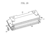
- FIG. 10 is a perspective view of the process of assembling the development unit according to the exemplary embodiment.
- FIG. 11 is a detailed perspective view of the process of assembling the development unit according to the exemplary embodiment.
- FIG. 12 is a perspective view of the process of assembling the development unit according to the exemplary embodiment.
- FIG. 13 is a perspective view of the process of assembling the development unit according to the exemplary embodiment.
- FIG. 14 is a perspective view of the process of assembling the development unit according to the exemplary embodiment.
- FIG. 15 is a side view of the development unit according to the exemplary embodiment.
- FIG. 1 is a diagram illustrating the overall configuration of the color electrophotographic image forming apparatus according to the present exemplary embodiment.
- FIG. 1 illustrates four image forming stations, namely first to fourth image forming stations Y, M, C, and Bk, for forming images using yellow, magenta, cyan, and black developers (hereinafter referred to as “toner”), respectively, corresponding to the color separation components of a full-color image.
- the image forming stations Y, M, C, and Bk are placed side by side within the apparatus main body 100 so as to be inclined relative to the horizontal direction.
- electrophotographic process units are placed around an electrophotographic photosensitive drum 1 ( 1 a , 1 b , 1 c , 1 d ) serving as an image bearing body.
- the electrophotographic process units include: a charging roller 2 ( 2 a , 2 b , 2 c , 2 d ) that uniformly charges the surface of the photosensitive drum 1 ; a development roller 25 ( 25 a , 25 b , 25 c , 25 d ) that develops and visualizes, using toner, a latent image formed on the photosensitive drum 1 ; and a cleaning member 6 ( 6 a , 6 b , 6 c , 6 d ) that removes the toner remaining on the photosensitive drum 1 after the toner image formed on the photosensitive drum 1 is transferred onto a recording medium.
- the photosensitive drum 1 , the charging roller 2 , the development roller 25 , and the cleaning member 6 are provided in a process cartridge 7 ( 7 a , 7 b , 7 c , 7 d ) in an integrated manner, attachable to and detachable from the apparatus main body 100 .
- a scanner unit 3 is provided attached to the image forming apparatus main body 100 , to perform a selective exposure on the photosensitive drums 1 a , 1 b , 1 c , and 1 d based on image information, thereby forming latent images on the respective photosensitive drums 1 a , 1 b , 1 c , and 1 d.
- a cassette 17 accommodating recording media S is mounted on a lower portion of the apparatus main body 100 . Further, a recording medium conveying unit is provided to convey the recording media S to an upper portion of the apparatus main body 100 through the positions of the photosensitive drums 1 a , 1 b , 1 c , and 1 d . That is, a feed roller 54 , a pair of conveyance rollers 76 , and a pair of registration rollers 55 are provided. The feed roller 54 separates and feeds the recording media S in the cassette 17 one by one. The pair of conveyance rollers 76 conveys the fed recording medium S.
- the pair of registration rollers 55 synchronizes the recording medium S with latent images to be formed on the respective photosensitive drums 1 a , 1 b , 1 c , and 1 d .
- an intermediate transfer unit 5 is provided as an intermediate transfer unit configured to transfer toner images formed on the respective photosensitive drums 1 a , 1 b , 1 c , and 1 d .
- the intermediate transfer unit 5 has a driving roller 56 , a driven roller 57 , a primary transfer roller 58 ( 58 a , 58 b , 58 c , 58 d ) at a position opposed to the photosensitive drum 1 of the corresponding color, and a counter roller 59 at a position opposed to a secondary transfer roller 70 , and a transfer belt 9 is stretched around these rollers.
- the transfer belt 9 circularly moves while being opposed to and in contact with all the photosensitive drums 1 a , 1 b , 1 c , and 1 d , and voltage is applied to the primary transfer roller 58 ( 58 a , 58 b , 58 c , 58 d ), thereby primarily transferring a toner image from the photosensitive drum 1 onto the transfer belt 9 .
- voltage is applied to the counter roller 59 , placed within the transfer belt 9 , and the secondary transfer roller 70 , thereby transferring the toner on the transfer belt 9 onto a recording medium S.
- Image formation is performed by rotating the photosensitive drum 1 and causing the scanner unit 3 to perform a selective exposure on the photosensitive drum 1 uniformly charged by the charging roller 2 .
- This forms an electrostatic latent image on the photosensitive drum 1 .
- the development roller 25 develops the latent image.
- This forms a toner image of each color on the corresponding photosensitive drum 1 .
- the pair of registration rollers 55 conveys a recording medium S to a secondary transfer position where the counter roller 59 and the secondary transfer roller 70 abut each other through the transfer belt 9 . Then, transfer bias voltage is applied to the secondary transfer roller 70 , thereby secondarily transferring the toner images of the respective colors on the transfer belt 9 onto the recording medium S.
- the recording medium S on which the color image has been formed as described above is heated and pressed by a fixing unit 74 to fix the toner images. Thereafter, the recording medium S is discharged to a discharge portion 75 by a discharge roller 72 . It should be noted that the fixing unit 74 is placed in an upper portion of the apparatus main body 100 .
- FIG. 3 is the principal section of the process cartridge 7 accommodating a developer (hereinafter referred to as “toner”). It should be noted that the cartridge 7 a accommodating yellow toner, the cartridge 7 b accommodating magenta toner, the cartridge 7 c accommodating cyan toner, and the cartridge 7 d accommodating black toner have similar configurations.
- the process cartridge 7 ( 7 a , 7 b , 7 c , 7 d ) includes: a cleaning unit 26 ( 26 a , 26 b , 26 c , 26 d ) having the photosensitive drum 1 ( 1 a , 1 b , 1 c , 1 d ), the charging roller 2 ( 2 a , 2 b , 2 c , 2 d ), and the cleaning member 6 ( 6 a , 6 b , 6 c , 6 d ); and a development unit 4 ( 4 a , 4 b , 4 c , 4 d ) as a development apparatus having a development roller.
- the photosensitive drum 1 is rotatably attached to a cleaning frame member 27 of the cleaning unit 26 through a drum-front bearing 10 and a drum-rear bearing 11 (see FIG. 4 ). On the periphery of the photosensitive drum 1 , the charging roller 2 and the cleaning member 6 are placed as described above.
- the residual toner removed from the surface of the photosensitive drum 1 by the cleaning member falls into a removed toner chamber 27 a .
- the driving force of a main body driving motor (not illustrated) is transmitted to the cleaning unit 26 , thereby driving the photosensitive drum 1 to rotate according to an image forming operation.
- the charging roller 2 is rotatably attached to the cleaning frame member through a charging roller bearing 28 .
- the charging roller 2 is pressed toward the photosensitive drum 1 by a charging roller pressing member 46 and is driven to rotate by the photosensitive drum 1 .
- the development unit 4 mainly includes a development frame member 31 , the development roller 25 , a toner supply roller 34 , a development blade 35 , and a toner conveying member 36 .
- the development frame member 31 accommodates toner.
- the development roller 25 is rotatably supported by the development frame member 31 through a development-front bearing 12 and a development-rear bearing 13 that are attached to respective ends of the development frame member 31 , and the development roller 25 is placed in an opening portion 31 s of the development frame member 31 .
- the development roller 25 bears the toner on its peripheral surface and is placed in contact with the photosensitive drum 1 . Then, the development roller 25 rotates about a development roller axis q (see FIG.
- the toner supply roller 34 has a urethane foam layer on its surface and has a supply roller shaft 34 h as a rotating shaft member.
- the toner supply roller 34 rotates in the direction of an arrow C in FIG. 3 in contact with the development roller 25 and supplies the toner to the development roller 25 .
- the development blade 35 regulates the thicknesses of the toner layers on the toner supply roller 34 and the development roller 25 .
- the toner conveying member 36 is provided in a toner accommodating portion 31 a of the development frame member 31 to agitate the accommodated toner and also convey the toner to the toner supply roller 34 .
- FIG. 4 is an external perspective view of the process cartridge 7 .
- the development unit 4 is attached to the cleaning unit 26 so as to be rotatable relative to the cleaning unit 26 .
- the development unit 4 is supported so as to be rotatable relative to the cleaning frame member 27 (see FIGS. 3 and 4 ) by engaging a front supporting pin 14 and a rear supporting pin 15 with suspension holes 12 a and 13 a (see FIG. 5 ) of the development-front bearing 12 and the development-rear bearing 13 , respectively.
- the front supporting pin 14 and the rear supporting pin 15 are press-fitted to the cleaning frame member 27 .
- the drum-front bearing 10 and the drum-rear bearing 11 are provided to rotatably support the photosensitive drum 1 .
- the drum-rear bearing 11 supports a drum coupling 16 , which is combined with the electrophotographic photosensitive drum 1 to transmit the driving force of the image forming apparatus main body 100 to the photosensitive drum 1 .
- the development unit 4 illustrated in FIG. 5 is configured to be urged toward the cleaning unit 26 by a pressure spring 38 provided in the development frame member 31 and a tension spring 39 provided in the development-front bearing 12 during the image formation of the process cartridge 7 .
- These springs generate a pressure force for bringing the development roller 25 into contact with the photosensitive drum 1 such that the holes 12 a and 13 a of the development-front bearing 12 and the development-rear bearing 13 are the center of rotational movement.
- the photosensitive drum 1 is desirably a rigid body
- the development roller 25 is a roller having an elastic body.
- the elastic body for example, a solid rubber monolayer or a solid rubber coated with a resin is used in consideration of the toner charging performance.
- the main body driving motor (not illustrated) starts rotating and transmits drive to the photosensitive drum 1 .
- the image forming apparatus main body 100 applies charging bias voltage to the charging roller 2 to uniformly charge the surface of the photosensitive drum 1 .
- the scanner unit 3 performs an exposure according to the image information to form a latent image on the photosensitive drum 1 .
- the developer conveying mechanism 36 feeds the toner in the development frame member 31 to the toner supply roller 34 .
- the toner supply roller 34 supplies the toner to the outer periphery of the development roller 25 .
- the development blade 35 frictionally charges the supplied toner on the outer periphery of the development roller 25 .
- the apparatus main body 100 applies development bias voltage to the development roller 25 , thereby developing the electrostatic latent image formed on the electrophotographic photosensitive drum 1 .
- the development roller 25 is placed so as to be opposed to the photosensitive drum 1 .
- the development roller 25 is configured to come into contact with the photosensitive drum 1 to develop the electrostatic latent image formed on the photosensitive drum 1 .
- the development frame member 31 has a through hole 31 f on the surface at one end side of the development frame member 31 .
- the through hole 31 f is formed to allow the insertion of the supply roller 34 into the development frame member 31 from the outside thereof in the direction of a supply roller axis p.
- the through hole 31 f has an insertion hole 31 fa (an insertion portion) into which the supply roller 34 is to be inserted, and a first guide hole 31 fb (a guide portion) for guiding the supply roller shaft 34 h .
- the insertion hole 31 fa is formed to have a diameter greater than the maximum outer diameter of the supply roller 34 (that is, a cross section of the through hole 31 f perpendicular to the supply roller axis p is greater than a cross section of the supply roller 34 perpendicular to the supply roller axis p), thereby facilitating the insertion of the supply roller 34 .
- a cross section of the through hole 31 f perpendicular to the supply roller axis p is greater than a cross section of the supply roller 34 perpendicular to the supply roller axis p
- the insertion hole 31 fa and the first guide hole 31 fb which are provided at one end side of the development frame member 31 , are connected together to allow the movement of the supply roller 34 .
- the supply roller shaft 34 h is moved from the position of the insertion hole 31 fa (see FIG. 8 ) to the position of the first guide hole 31 fb (in a direction R in FIG. 9 ), and the supply roller 34 is held.
- a bush member 81 as a second sealing member for sealing the through hole 31 f is assembled to the development frame member 31 , so that the first guide hole 31 fb provided in the development frame member 31 and a third guide hole 81 a provided in the bush member 81 (see FIG. 11 ) guide and hold the supply roller shaft 34 h.
- the bush member 81 is made of polystyrene.
- the bush member 81 increases the stiffness of the development frame member 31 around the insertion hole 31 fa by fitting the insertion hole 31 fa provided in the development frame member 31 (see FIG. 2A ).
- An end sealing member 83 is pasted to a supporting portion 31 k of the development frame member 31 and supported.
- the development roller 25 is assembled to the development frame member 31 so as to abut the end sealing member 83 .
- the end sealing member 83 functions as a first sealing member for sealing the gap between the peripheral surface of the development roller 25 and the supporting portion 31 k of the frame member 31 in at one end side of said frame member 31 in the axis direction of the development roller 25 .
- the development roller 25 and the development frame member 31 are positioned by the bearing members ( 12 and 13 ).
- the end sealing member 83 and the supporting portion 31 k are located between the development roller 25 and the through hole 31 f , so that the end sealing member 83 is compressively held by the development roller 25 and the supporting portion 31 k .
- a force P 1 generated by the development roller 25 abutting the end sealing member 83 is applied to the supporting portion 31 k of the development frame member 31 (see FIG. 15 ).
- the supporting portion 31 k from deforming (to prevent the through hole 31 f from deforming) by the force P 1 , as illustrated in FIG.
- FIG. 2B is a cross-sectional view of a bush member fitting portion in a state where the end sealing member 83 is pasted to the supporting portion 31 k in FIG. 2A (a cross-sectional view in a vertical plane passing through the center of the insertion hole 31 f and parallel to the supply roller axis p).
- the bush member 81 fits the insertion hole 31 fa to support the back surface of the supporting portion 31 k (a part of the inner surface of the through hole 31 f ).
- the end sealing member 83 and the bush member 81 are provided so as to be located on the same plane perpendicular to the direction of the development roller axis q. With this configuration, it is possible to suppress the deformation of the supporting portion 31 k under the influence of the force P 1 .
- the bush member 81 is provided from one end to the other end of the through hole 31 f in the direction of the development roller axis q to support the back surface of the supporting portion 31 k .
- the bush member 81 is provided from one end to the other end of the through hole 31 f in the direction of the development roller axis q to support the back surface of the supporting portion 31 k .
- the bush member 81 is made of polystyrene.
- the material of the bush member 81 should be a thermoplastic material such as polycarbonate, polypropylene, or an acrylonitrile-butadiene-styrene (ABS) resin.
- ABS acrylonitrile-butadiene-styrene
- the material should have a tensile strength of 20 MPa or more (JIS K7113).
- the tensile strength (JIS g0202) of each of the rotating shafts 34 g and 34 h of the supply roller 34 is greater than the tensile strength of the bush member 81 , and as illustrated in FIG. 2A , the rotating shaft 34 h of the supply roller 34 is placed at a position opposed to the back surface of the supporting portion 31 k .
- This enables not only the bush member 81 but also the rotating shaft 34 h of the supply roller 34 to contribute to suppressing the deformation of the supporting portion 31 k when the supporting portion 31 k is subjected to the force P 1 .
- the development roller axis q is parallel to the supply roller axis p, and “the axis direction of the supply roller” represents the same direction as “the axis direction of the development roller”.
- the rotating shafts 34 g and 34 h of the supply roller 34 are designated by different numerals for convenience, but represent the same member.
Landscapes
- Physics & Mathematics (AREA)
- General Physics & Mathematics (AREA)
- Electrophotography Configuration And Component (AREA)
- Dry Development In Electrophotography (AREA)
Applications Claiming Priority (2)
| Application Number | Priority Date | Filing Date | Title |
|---|---|---|---|
| JP2012-127135 | 2012-06-04 | ||
| JP2012127135A JP6137786B2 (ja) | 2012-06-04 | 2012-06-04 | 現像装置、プロセスカートリッジ、画像形成装置 |
Publications (2)
| Publication Number | Publication Date |
|---|---|
| US20130322921A1 US20130322921A1 (en) | 2013-12-05 |
| US9239544B2 true US9239544B2 (en) | 2016-01-19 |
Family
ID=49670409
Family Applications (1)
| Application Number | Title | Priority Date | Filing Date |
|---|---|---|---|
| US13/906,816 Active US9239544B2 (en) | 2012-06-04 | 2013-05-31 | Development apparatus, process cartridge, and image forming apparatus |
Country Status (2)
| Country | Link |
|---|---|
| US (1) | US9239544B2 (enExample) |
| JP (1) | JP6137786B2 (enExample) |
Cited By (1)
| Publication number | Priority date | Publication date | Assignee | Title |
|---|---|---|---|---|
| US10936586B2 (en) | 2017-11-29 | 2021-03-02 | Wipro Limited | Method and system for providing domain-specific response to a user query |
Families Citing this family (4)
| Publication number | Priority date | Publication date | Assignee | Title |
|---|---|---|---|---|
| JP6584138B2 (ja) | 2014-06-17 | 2019-10-02 | キヤノン株式会社 | 現像カートリッジ、プロセスカートリッジ及び画像形成装置 |
| JP6525683B2 (ja) * | 2015-03-31 | 2019-06-05 | キヤノン株式会社 | 現像装置、プロセスカートリッジおよび画像形成装置 |
| US11126138B2 (en) * | 2019-08-28 | 2021-09-21 | Lexmark International, Inc. | Bushing assembly for an electrophotographic image forming device |
| JP7764165B2 (ja) * | 2021-08-27 | 2025-11-05 | キヤノン株式会社 | 現像ユニット |
Citations (3)
| Publication number | Priority date | Publication date | Assignee | Title |
|---|---|---|---|---|
| JP2006208689A (ja) | 2005-01-27 | 2006-08-10 | Seiko Epson Corp | 現像装置、画像形成装置、画像形成システム、及び、現像剤供給ローラの組み付け方法 |
| US20110236058A1 (en) * | 2010-03-24 | 2011-09-29 | Brother Kogyo Kabushiki Kaisha | Developing Device |
| US20130051857A1 (en) | 2011-08-31 | 2013-02-28 | Brother Kogyo Kabushiki Kaisha | Developing Device Provided with Developing Roller and Supply Roller |
Family Cites Families (1)
| Publication number | Priority date | Publication date | Assignee | Title |
|---|---|---|---|---|
| JP2002202660A (ja) * | 2000-12-28 | 2002-07-19 | Canon Inc | 現像装置、プロセスカートリッジ、及び電子写真画像形成装置 |
-
2012
- 2012-06-04 JP JP2012127135A patent/JP6137786B2/ja active Active
-
2013
- 2013-05-31 US US13/906,816 patent/US9239544B2/en active Active
Patent Citations (3)
| Publication number | Priority date | Publication date | Assignee | Title |
|---|---|---|---|---|
| JP2006208689A (ja) | 2005-01-27 | 2006-08-10 | Seiko Epson Corp | 現像装置、画像形成装置、画像形成システム、及び、現像剤供給ローラの組み付け方法 |
| US20110236058A1 (en) * | 2010-03-24 | 2011-09-29 | Brother Kogyo Kabushiki Kaisha | Developing Device |
| US20130051857A1 (en) | 2011-08-31 | 2013-02-28 | Brother Kogyo Kabushiki Kaisha | Developing Device Provided with Developing Roller and Supply Roller |
Cited By (1)
| Publication number | Priority date | Publication date | Assignee | Title |
|---|---|---|---|---|
| US10936586B2 (en) | 2017-11-29 | 2021-03-02 | Wipro Limited | Method and system for providing domain-specific response to a user query |
Also Published As
| Publication number | Publication date |
|---|---|
| US20130322921A1 (en) | 2013-12-05 |
| JP2013250514A (ja) | 2013-12-12 |
| JP6137786B2 (ja) | 2017-05-31 |
Similar Documents
| Publication | Publication Date | Title |
|---|---|---|
| JP5943685B2 (ja) | 現像ユニット、プロセスカートリッジ、及び電子写真画像形成装置 | |
| JP5349999B2 (ja) | プロセスカートリッジおよび画像形成装置 | |
| US9632479B2 (en) | Process cartridge and image forming apparatus | |
| US20170248869A1 (en) | Developing cartridge and image forming apparatus | |
| JP2006071808A (ja) | プロセスカートリッジ及び電子写真画像形成装置 | |
| US10139774B2 (en) | Developing device and image forming apparatus | |
| US9239544B2 (en) | Development apparatus, process cartridge, and image forming apparatus | |
| US9081323B2 (en) | Developing device, process cartridge, and image forming apparatus | |
| US10241438B2 (en) | Developing device having a developing unit that is pivotally supported about the axis of a shaft, and image forming apparatus | |
| US20130121721A1 (en) | Developer conveyance apparatus developing apparatus and process cartridge | |
| US11016411B2 (en) | Process cartridge, developing apparatus, and image forming apparatus | |
| EP3163376B1 (en) | Image forming apparatus that ensures highly accurate positioning on photoreceptor drum of primary transfer roller | |
| US10838353B2 (en) | Developing apparatus | |
| CN114518700B (zh) | 像载体单元及具备该像载体单元的图像形成装置 | |
| JP5866885B2 (ja) | 感光体ユニットおよび画像形成装置 | |
| US10895825B2 (en) | Developer accommodating container, developing device and process cartridge | |
| JP6639632B2 (ja) | 画像形成装置 | |
| JP2022016058A (ja) | 像担持体ユニットおよびそれを備えた画像形成装置 | |
| JP6129383B2 (ja) | 現像ユニット、プロセスカートリッジ、及び電子写真画像形成装置 | |
| KR20190114917A (ko) | 현상제 용기, 현상 장치 및 프로세스 카트리지 | |
| PH12017000055A1 (en) | Developing cartridge and image forming apparatus | |
| JP2014071422A (ja) | 現像剤収納ユニット、現像ユニット、及びプロセスカートリッジ | |
| JP2025033149A (ja) | 画像形成装置 | |
| JP2014119590A (ja) | 現像装置及びプロセスカートリッジ | |
| JP2005070186A (ja) | プロセスカートリッジ及び電子写真画像形成装置 |
Legal Events
| Date | Code | Title | Description |
|---|---|---|---|
| AS | Assignment |
Owner name: CANON KABUSHIKI KAISHA, JAPAN Free format text: ASSIGNMENT OF ASSIGNORS INTEREST;ASSIGNORS:MAESHIMA, HIDEKI;HIRUKAWA, KUNIAKI;GOFUKU, SHUICHI;SIGNING DATES FROM 20130516 TO 20130517;REEL/FRAME:031262/0400 |
|
| STCF | Information on status: patent grant |
Free format text: PATENTED CASE |
|
| MAFP | Maintenance fee payment |
Free format text: PAYMENT OF MAINTENANCE FEE, 4TH YEAR, LARGE ENTITY (ORIGINAL EVENT CODE: M1551); ENTITY STATUS OF PATENT OWNER: LARGE ENTITY Year of fee payment: 4 |
|
| MAFP | Maintenance fee payment |
Free format text: PAYMENT OF MAINTENANCE FEE, 8TH YEAR, LARGE ENTITY (ORIGINAL EVENT CODE: M1552); ENTITY STATUS OF PATENT OWNER: LARGE ENTITY Year of fee payment: 8 |