US9217865B2 - Light projection device - Google Patents
Light projection device Download PDFInfo
- Publication number
- US9217865B2 US9217865B2 US14/113,695 US201214113695A US9217865B2 US 9217865 B2 US9217865 B2 US 9217865B2 US 201214113695 A US201214113695 A US 201214113695A US 9217865 B2 US9217865 B2 US 9217865B2
- Authority
- US
- United States
- Prior art keywords
- light
- projection
- shadow region
- range
- projector
- Prior art date
- Legal status (The legal status is an assumption and is not a legal conclusion. Google has not performed a legal analysis and makes no representation as to the accuracy of the status listed.)
- Expired - Fee Related, expires
Links
- 230000001678 irradiating effect Effects 0.000 claims abstract description 6
- 238000005286 illumination Methods 0.000 claims description 29
- 238000001514 detection method Methods 0.000 claims description 13
- 238000012937 correction Methods 0.000 claims description 10
- 230000004907 flux Effects 0.000 claims description 5
- 238000009877 rendering Methods 0.000 claims description 5
- 238000012545 processing Methods 0.000 description 11
- 238000006243 chemical reaction Methods 0.000 description 4
- 238000010586 diagram Methods 0.000 description 4
- 230000003287 optical effect Effects 0.000 description 4
- 238000005516 engineering process Methods 0.000 description 3
- 230000000694 effects Effects 0.000 description 2
- 238000003384 imaging method Methods 0.000 description 2
- 238000000034 method Methods 0.000 description 2
- 239000000470 constituent Substances 0.000 description 1
- 238000013461 design Methods 0.000 description 1
- 238000012986 modification Methods 0.000 description 1
- 230000004048 modification Effects 0.000 description 1
Images


Classifications
-
- G—PHYSICS
- G02—OPTICS
- G02B—OPTICAL ELEMENTS, SYSTEMS OR APPARATUS
- G02B27/00—Optical systems or apparatus not provided for by any of the groups G02B1/00 - G02B26/00, G02B30/00
- G02B27/0025—Optical systems or apparatus not provided for by any of the groups G02B1/00 - G02B26/00, G02B30/00 for optical correction, e.g. distorsion, aberration
-
- F—MECHANICAL ENGINEERING; LIGHTING; HEATING; WEAPONS; BLASTING
- F21—LIGHTING
- F21V—FUNCTIONAL FEATURES OR DETAILS OF LIGHTING DEVICES OR SYSTEMS THEREOF; STRUCTURAL COMBINATIONS OF LIGHTING DEVICES WITH OTHER ARTICLES, NOT OTHERWISE PROVIDED FOR
- F21V33/00—Structural combinations of lighting devices with other articles, not otherwise provided for
-
- G—PHYSICS
- G01—MEASURING; TESTING
- G01J—MEASUREMENT OF INTENSITY, VELOCITY, SPECTRAL CONTENT, POLARISATION, PHASE OR PULSE CHARACTERISTICS OF INFRARED, VISIBLE OR ULTRAVIOLET LIGHT; COLORIMETRY; RADIATION PYROMETRY
- G01J1/00—Photometry, e.g. photographic exposure meter
- G01J1/42—Photometry, e.g. photographic exposure meter using electric radiation detectors
- G01J1/4228—Photometry, e.g. photographic exposure meter using electric radiation detectors arrangements with two or more detectors, e.g. for sensitivity compensation
-
- H—ELECTRICITY
- H04—ELECTRIC COMMUNICATION TECHNIQUE
- H04N—PICTORIAL COMMUNICATION, e.g. TELEVISION
- H04N9/00—Details of colour television systems
- H04N9/12—Picture reproducers
- H04N9/31—Projection devices for colour picture display, e.g. using electronic spatial light modulators [ESLM]
- H04N9/3179—Video signal processing therefor
- H04N9/3182—Colour adjustment, e.g. white balance, shading or gamut
-
- H—ELECTRICITY
- H04—ELECTRIC COMMUNICATION TECHNIQUE
- H04N—PICTORIAL COMMUNICATION, e.g. TELEVISION
- H04N9/00—Details of colour television systems
- H04N9/12—Picture reproducers
- H04N9/31—Projection devices for colour picture display, e.g. using electronic spatial light modulators [ESLM]
- H04N9/3191—Testing thereof
- H04N9/3194—Testing thereof including sensor feedback
-
- F—MECHANICAL ENGINEERING; LIGHTING; HEATING; WEAPONS; BLASTING
- F21—LIGHTING
- F21S—NON-PORTABLE LIGHTING DEVICES; SYSTEMS THEREOF; VEHICLE LIGHTING DEVICES SPECIALLY ADAPTED FOR VEHICLE EXTERIORS
- F21S2/00—Systems of lighting devices, not provided for in main groups F21S4/00 - F21S10/00 or F21S19/00, e.g. of modular construction
-
- F—MECHANICAL ENGINEERING; LIGHTING; HEATING; WEAPONS; BLASTING
- F21—LIGHTING
- F21V—FUNCTIONAL FEATURES OR DETAILS OF LIGHTING DEVICES OR SYSTEMS THEREOF; STRUCTURAL COMBINATIONS OF LIGHTING DEVICES WITH OTHER ARTICLES, NOT OTHERWISE PROVIDED FOR
- F21V23/00—Arrangement of electric circuit elements in or on lighting devices
- F21V23/04—Arrangement of electric circuit elements in or on lighting devices the elements being switches
- F21V23/0442—Arrangement of electric circuit elements in or on lighting devices the elements being switches activated by means of a sensor, e.g. motion or photodetectors
- F21V23/0464—Arrangement of electric circuit elements in or on lighting devices the elements being switches activated by means of a sensor, e.g. motion or photodetectors the sensor sensing the level of ambient illumination, e.g. dawn or dusk sensors
-
- F—MECHANICAL ENGINEERING; LIGHTING; HEATING; WEAPONS; BLASTING
- F21—LIGHTING
- F21W—INDEXING SCHEME ASSOCIATED WITH SUBCLASSES F21K, F21L, F21S and F21V, RELATING TO USES OR APPLICATIONS OF LIGHTING DEVICES OR SYSTEMS
- F21W2131/00—Use or application of lighting devices or systems not provided for in codes F21W2102/00-F21W2121/00
- F21W2131/40—Lighting for industrial, commercial, recreational or military use
- F21W2131/405—Lighting for industrial, commercial, recreational or military use for shop-windows or displays
-
- G—PHYSICS
- G01—MEASURING; TESTING
- G01J—MEASUREMENT OF INTENSITY, VELOCITY, SPECTRAL CONTENT, POLARISATION, PHASE OR PULSE CHARACTERISTICS OF INFRARED, VISIBLE OR ULTRAVIOLET LIGHT; COLORIMETRY; RADIATION PYROMETRY
- G01J1/00—Photometry, e.g. photographic exposure meter
- G01J1/10—Photometry, e.g. photographic exposure meter by comparison with reference light or electric value provisionally void
- G01J1/20—Photometry, e.g. photographic exposure meter by comparison with reference light or electric value provisionally void intensity of the measured or reference value being varied to equalise their effects at the detectors, e.g. by varying incidence angle
- G01J1/22—Photometry, e.g. photographic exposure meter by comparison with reference light or electric value provisionally void intensity of the measured or reference value being varied to equalise their effects at the detectors, e.g. by varying incidence angle using a variable element in the light-path, e.g. filter, polarising means
- G01J1/24—Photometry, e.g. photographic exposure meter by comparison with reference light or electric value provisionally void intensity of the measured or reference value being varied to equalise their effects at the detectors, e.g. by varying incidence angle using a variable element in the light-path, e.g. filter, polarising means using electric radiation detectors
- G01J1/26—Photometry, e.g. photographic exposure meter by comparison with reference light or electric value provisionally void intensity of the measured or reference value being varied to equalise their effects at the detectors, e.g. by varying incidence angle using a variable element in the light-path, e.g. filter, polarising means using electric radiation detectors adapted for automatic variation of the measured or reference value
-
- G—PHYSICS
- G03—PHOTOGRAPHY; CINEMATOGRAPHY; ANALOGOUS TECHNIQUES USING WAVES OTHER THAN OPTICAL WAVES; ELECTROGRAPHY; HOLOGRAPHY
- G03B—APPARATUS OR ARRANGEMENTS FOR TAKING PHOTOGRAPHS OR FOR PROJECTING OR VIEWING THEM; APPARATUS OR ARRANGEMENTS EMPLOYING ANALOGOUS TECHNIQUES USING WAVES OTHER THAN OPTICAL WAVES; ACCESSORIES THEREFOR
- G03B15/00—Special procedures for taking photographs; Apparatus therefor
- G03B15/02—Illuminating scene
- G03B15/06—Special arrangements of screening, diffusing, or reflecting devices, e.g. in studio
- G03B15/07—Arrangements of lamps in studios
Definitions
- the present invention relates to a light projection device that projects light onto an object.
- illumination light is desired to be irradiated onto a mannequin equipped with a commercial article.
- conventional technologies there have been performed: light irradiation onto the mannequin by a spotlight and the like; control for a shape of irradiation light, which is performed so that only the mannequin can be illuminated in such a manner that a shape of the mannequin and a positional relationship thereof with a lighting fixture are measured; and the like.
- Patent Literatures 1 and 2 a light projection device and a lighting device have been known, which are capable of projecting light with a shape, which is desired by a user, by controlling a shape of projection light.
- the spotlight irradiates circular light. Therefore, only an object cannot be irradiated, and leak light occurs on a background portion of the object. Accordingly, only a part of the object has been irradiated. Meanwhile, with regard to the case where movement and deformation of the object occur, it is possible to allow the light to follow movement and deformation, which are determined in advance; however, it is necessary to change a position and orientation of the lighting device itself.
- the present invention has been proposed in consideration of the above-mentioned circumstances. It is an object of the present invention to provide a light projection device capable of irradiating light only onto the object.
- a light projection device that projects light onto an object arranged in an arbitrary space, including: a light projector that projects projection light, in which the object and a back surface of the object are taken as a projectable range; a shadow region detector that detects a shadow region occurring on the back surface of the object by the projection light projected from the light projector; a shadow region corrector that corrects the shadow region, which is detected by the shadow region detector, so that a projection region of the light projector and the shadow region detected by the shadow region detector can coincide with each other on the back surface of the object; a projection range setting unit that sets, as a light projection range, the shadow region corrected by the shadow region corrector, and sets, as a non-light projection range, a region other than the shadow region; and a projection light setting unit that sets projection light projected onto the light projection range set by the projection range setting unit, characterized in that the light projector projects the projection light, which is set by the projection light setting unit, onto
- a light projection device is the light projection device according to the first aspect, characterized in that the projection light setting unit specifies an element including any of illuminance, brightness, luminous intensity, luminous flux, color temperature and color rendering properties of the projection light projected by the light projector.
- a light projection device is the light projection device according to either one of the first and second aspects, characterized in that the shadow region corrected by the shadow region corrector is taken as a first projection range, and a region other than the shadow region, is taken as a second projection range, the projection light setting unit individually sets light projected onto the first projection range and the second projection range, and the projectable region of the light projector is divided into the first projection range where the object is present and the second projection range where the object is not present, and the light projector projects different pieces of light onto the first projection range and the second projection range.
- a light projection device is the light projection device according to any one of the first to third aspects, characterized in that a shadow detection operation by the shadow region detector, a shadow region correction operation by the shadow region corrector, and a projection range setting operation by the projection range setting unit are performed at an arbitrary time interval.
- a light projection device is the light projection device according to any one of the first to fourth aspects, characterized in that the shadow region detector includes a black light projector that projects black light onto a region including the projectable range of the light projector, and detects a shadow region formed of the black light projected by the black light projector.
- a light projection device is the light projection device according to any one of the first to fifth aspects, characterized in that the light projector is configured to project the projection light from two or more positions, and the projection range setting unit sets the projection range for each of light projection positions.
- a light projection device is the light projection device according to any one of the first to fifth aspects, characterized in that the shadow region detector is configured to detect the shadow regions from two or more positions, the shadow region corrector calculates the shadow region corrected for each of shadow region detection positions, and the projection range setting unit integrates the respective shadow regions corrected by the shadow region corrector, and sets the projection range of the light projector.
- a light projection device is the light projection device according to any one of the first to seventh aspects, characterized in that the shadow region detector is composed of a light sensor embedded in the back surface of the object.
- a light projection device is the light projection device according to any one of the first to eighth aspects, characterized in that it is possible to adjust timing of generation of illumination data for projecting the projection light as illumination light by the light projector, the generation being performed by an illumination data generator that generates the illumination data, and irradiation timing of the illumination light by the light projector.
- a light projection device is the light projection device according to any one of the first to ninth aspects, characterized in that the light projector projects a video, and the projection light setting unit sets a video as the light projected from the light projector.
- the shadow region of the object is detected, and the shadow region is corrected so that the projection region of the light projector and the shadow region can coincide with each other on the back surface, and the shadow region thus corrected is set as the light projection range, and accordingly, the projection light can be projected onto the range where the object is present.
- the projection light can be irradiated only onto the object.
- FIG. 1 is a perspective view showing a configuration of a light projection device shown as a first embodiment of the present invention.
- FIG. 2 is a block diagram showing the configuration of the light projection device shown as the first embodiment of the present invention.
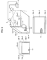
- FIG. 3 is a view showing a perspective view in the light projection device shown as the first embodiment of the present invention, and showing a top view and front view of a shadow region.
- FIG. 4 is a flowchart showing an operation procedure of the light projection device shown as the first embodiment of the present invention.
- FIG. 5 is a perspective view showing a configuration of a light projection device shown as a second embodiment of the present invention.
- FIG. 6 is a block diagram showing the configuration of the light projection device shown as the second embodiment of the present invention.
- FIG. 7 is a perspective view showing another configuration of the light projection device shown as the second embodiment of the present invention.
- FIG. 8 is a perspective view showing a configuration of a light projection device shown as a third embodiment of the present invention.
- FIG. 9 is a block diagram showing the configuration of the light projection device shown as the third embodiment of the present invention.
- FIG. 10 is a perspective view showing a configuration of a light projection device shown as a fourth embodiment of the present invention.
- FIG. 11 is a block diagram showing the configuration of the light projection device shown as the fourth embodiment of the present invention.
- FIG. 12 is a perspective view showing a configuration of a light projection device shown as a fifth embodiment of the present invention.
- a light projection device shown as an embodiment of the present is configured, for example, as shown in FIG. 1 .
- This light projection device is one that projects projection light L 1 onto an irradiation target object 11 arranged in an arbitrary space.
- the irradiation target object 11 for example, a commercial article, a mannequin or the like in a showroom is assumed. Moreover, the irradiation target object 11 may be a deformable or movable one. The irradiation target object 11 is placed on a floor surface 12 a as a background region. Moreover, a back surface 12 b is provided behind the irradiation target object 11 .
- the light projection device includes a light projector 1 , a shadow region detector 2 , and a controller 3 .
- the irradiation target object 11 and the floor surface 12 a and the back surface 12 b which serve as back surface regions of the irradiation target object 11 , are taken as a projectable range.
- the light projector 1 projects the projection light L 1 onto the irradiation target object 11 in accordance with control of the controller 3 .
- the light projector 1 is realizable, for example, by a projector that projects illumination light and video light, and the like.
- the shadow region detector 2 detects a shadow region 13 of the irradiation target object 11 , which is generated on the floor surface 12 a and the back surface 12 b by the projection light L 1 projected from the light projector 1 .
- This shadow region 13 is determined by a positional relationship between the light projector 1 and the irradiation target object 11 , and by a shape of the irradiation target object 11 .
- This shadow region detector 2 takes, as an imaging range 2 a , the floor surface 12 a and the back surface 12 b , which include the shadow region 13 of the irradiation target object 11 , and is realizable by a camera that acquires image data, and the like.
- the controller 3 controls operations of the light projector 1 and the shadow region detector 2 .
- This controller 3 is composed, for example, a computer or the like, in which a CPU executes a program for controlling the light projector 1 and the shadow region detector 2 , whereby control signals and the like are outputted to the light projector 1 and the shadow region detector 2 .
- the controller 3 includes a shadow region corrector 31 , a projection range setting unit 32 and a projection light setting unit 33 as functional constituents thereof.
- the shadow region corrector 31 acquires the shadow region 13 detected by the shadow region detector 2 .
- the shadow region 13 is detected, for example, by the image data by the shadow region detector 2 .
- the shadow region corrector 31 recognizes dark pixels, which are equivalent to a shadow of the irradiation target object 11 , as the shadow region 13 .
- the shadow region corrector 31 corrects the shadow region 13 , which is detected by the shadow region detector 2 , so that a projection range of the light projector 1 and the shadow region 13 detected by the shadow region detector 2 can coincide with each other on the floor surface 12 a and the back surface 12 b .
- the shadow region corrector 31 acquires the shadow region 13 detected by the shadow region detector 2 at the time when the projection light L 1 is irradiated by the light projector 1 onto a wide range including the irradiation target object 11 . Then, based on a position and shape of the acquired shadow region 13 , the shadow region corrector 31 specifies the projection light L 1 that is projected onto the position of the shadow region 13 .
- the shadow region corrector 31 performs projection conversion so that an optical axis of the light projector 1 and an optical axis of the shadow region detector 2 with respect to the specific floor surface 12 a and back surface 12 b can be matched with each other.
- the shadow region corrector 31 allows coincidence between projection spots of the light projector 1 and detection spots of the shadow region 13 on the floor surface 12 a and the back surface 12 b . That is to say, the shadow region corrector 31 performs image processing for correcting a projected image of the light projector 1 and the imaged image of the shadow region detector 2 so that the projected image and the imaged image can coincide with each other on the same plane.
- the projection range onto which the projection light L 1 is projectable by the light projector 1 is 12 a - 1 , 12 b - 1 and 12 b - 6 .
- a detectable range of the shadow region 13 by the shadow region detector 2 is 12 a - 2 , 12 a - 3 , 12 b - 2 and 12 b - 4 in addition to 12 a - 1 and 12 b - 1 .
- 3( b ) and 3 ( c ) make a range where the projection range onto which the projection light L 1 is projectable by the light projector 1 and the detectable range of the shadow region 13 by the shadow region detector 2 overlap each other.
- a correspondence relationship between the projection light L 1 and the shadow region 13 is clear. That is to say, if the pixels of the shadow region 13 are known, then it is known which part of the projection light L 1 makes the shadow region 13 .
- this overlap range is a smaller one between such a range which the projection light L reaches and the detectable range of the shadow region 13 , and this smaller one becomes a part of a larger one.
- the shadow region corrector 31 calculates in advance a correspondence relationship between each pixel of the image acquired by the shadow region detector 2 and the projection light L 1 of the light projector, and creates and prestores a correspondence map. In the case of having acquired an image obtained by actually imaging the shadow region 13 by the shadow region detector 2 , the shadow region corrector 31 refers to the correspondence map concerned, and performs light specification for the projection light L 1 corresponding to the shadow region 13 .
- the projection range setting unit 32 sets a correction region of the shadow, which is corrected by the shadow region corrector 31 , as a light projection range, and sets a region, which is other than the light projection range, as a non-light projection range.
- the projection range setting unit 32 may set a region, which corresponds to the shadow region 13 , as a first projection range, and may set a region, which is other than the first projection range, as a second projection range.
- the projection range setting unit 32 can set the projection range L 1 individually for each of the first projection range and the second projection range. In such a way, different pieces of the projection light L 1 can be projected onto such a region where the irradiation target object 11 is present, and onto a region other than the region concerned.
- the projection light setting unit 33 sets light, which is projected onto the light projection range set by the projection range setting unit 32 .
- the projection light setting unit 33 sets light, which is projected onto the projection range set by the projection range setting unit 32 , or onto the first projection range and the second projection range.
- the projection light setting unit 33 sets illumination light and video light, which are projected individually for each of the above.
- the projection light setting unit 33 may have a function capable of specifying elements including illuminance, brightness, luminous intensity, luminous flux, color temperature and color rendering properties of the projection light L 1 . In such a way, the light projection device can set the projection light L 1 by parameters for use in lighting.
- the projection range setting unit 32 may set black light on the first projection range. In such a way, it is also made possible not to project the light onto the irradiation target object 11 .
- the light projection device as described above operates, for example, as shown in FIG. 4 .
- Step S 1 the light projection device projects the projection light L 1 onto the whole of the projectable range, which includes the irradiation target object 11 , the floor surface 12 a and the back surface 12 b , by the light projector 1 .
- Step S 2 the shadow region detector 2 detects the shadow region 13 , which is generated on the floor surface 12 a and the back surface 12 b , in a state where the projection light L 1 is projected by the light projector 1 .
- the shadow region corrector 31 refers to the image data detected by the shadow region detector 2 , and determines whether or not an image region equivalent to the shadow region 13 is present. In such a way, the shadow region corrector 31 determines whether or not the shadow region 13 is detected. In the case where the shadow region 13 is detected, the processing is advanced to Step S 4 , and in the case where the shadow region 13 is not detected, the processing is returned to Step S 1 . In the case where the processing is returned to Step S 1 , Step S 1 to Step S 3 are repeated until the shadow is extracted by the shadow region corrector 31 as a result of projecting the projection light L 1 from the light projector 1 .
- the shadow region corrector 31 specifies the projection light L 1 of the light projector 1 , which corresponds to the detected shadow region 13 .
- the shadow region corrector 31 performs the projection conversion so that the optical axis of the light projector 1 and the optical axis of the shadow region detector 2 on the floor surface 12 a and the back surface 12 b can be matched with each other, and allows the coincidence between the projection spots on the floor surface 12 a and the back surface 12 b and the detection spots of the shadow region 13 .
- the shadow region corrector 31 performs such a projection conversion operation as described above, or performs the projection conversion by using the correspondence map prepared in advance, and thereby specifies the projection light L 1 with respect to the shadow region 13 .
- Step S 5 in the case of irradiating the projection light L 1 only onto the irradiation target object 11 , the projection range setting unit 32 sets such a correction region of the shadow region 13 , which is corrected by the shadow region corrector 31 , as the light projection range, and sets the region, which is other than the light projection range, as the non-light projection range.
- the projection range setting unit 32 sets the region, which corresponds to the shadow region 13 , as the first projection range, and sets the region, which is other than the first projection range, as the second projection range.
- the projection light setting unit 33 sets the projection light L 1 , which is projected onto the light projection range set by the projection range setting unit 32 .
- the projection light setting unit 33 makes setting that the illumination light is to be projected.
- the projection light setting unit 33 sets the illumination light and the video light, which are projected individually for each thereof.
- the projection light setting unit 33 sets the element including any of the illuminance, the brightness, the luminous intensity, the luminous flux, the color temperature and the color rendering properties. Moreover, the projection light setting unit 33 sets the black light on the first projection range, and sets the illumination light and the video on the second projection range, thus making it possible not to project the light onto the irradiation target object 11 . Moreover, in the case where the projection light L 1 is the video light, the projection light setting unit 33 sets the video, which is projected as the projection light L 1 .
- the shadow region 13 of the irradiation target object 11 is detected, and is corrected so as to coincide with the projection region of the light projector 1 on the floor surface 12 a and the back surface 12 b , and the shadow region 13 thus corrected is set as the light projection range.
- the light projector 1 projects the projection light L 1 onto the set light projection range, and can thereby project the projection light L 1 onto the range where the irradiation target object 11 is present.
- the projection light L 1 can be irradiated only onto the irradiation target object 11 .
- this projection device it is not necessary for this projection device to measure the shape of the irradiation target object 11 , and so on in advance, and this projection device can irradiate the projection light L 1 , which is neither too much nor too little, onto the irradiation target object 11 .
- the element including any of the illuminance, brightness, luminous intensity, luminous flux, color temperature and color rendering properties of the projection light L 1 can be specified, and accordingly, the projection light L 1 projected onto the irradiation target object 11 can be adjusted.
- the shadow region 13 as the range where the irradiation target object 11 is irradiated is set as the first projection range
- the region other than the first projection range, which is such as the floor surface 12 a and the back surface 12 b is set as the second projection range.
- the projection light L 1 projected onto the first projection range and the second projection range can be set individually, and the different pieces of projection light L 1 can be projected individually thereonto.
- the light projector 1 may project the projection light L 1 as the illumination light.
- the light projection device is capable of adjusting timing of generation of illumination data for projecting the projection light L 1 as the illumination light by the light projector 1 , the generation being performed by an illumination data generator that generates the illumination data.
- the controller 3 is capable of adjusting irradiation timing of the illumination light by the light projector 1 .
- the generation timing of the illumination data is controlled, whereby such generation processing of the illumination data can also be stopped, and a processing load of the controller 3 can be reduced.
- the controller 3 can apply the processing load to shadow region correction processing, projection range setting processing and projection light setting processing.
- the generation processing of the illumination data by the controller 3 is stopped, whereby electrical power consumption of the controller 3 can be suppressed.
- the light projection device as the second embodiment is one capable of projecting the projection light L 1 onto the irradiation target object 11 even in the case where the irradiation target object 11 is deformed or moved.
- this light projection device performs a shadow detection operation by the shadow region detector 2 , a shadow region correction operation by the shadow region corrector 31 , and a projection range setting operation by the projection range setting unit 32 .
- the projection range of the projection light L 1 can be automatically updated, and such an operation of projecting the different pieces of projection light L 1 onto the irradiation target object 11 and onto the floor surface 12 a and the back surface 12 b , which are other than the irradiation target object 11 , can be maintained.
- the projection light L 1 is irradiated onto the projectable range of the light projector 1 one more time by the light projector 1 concerned.
- the shadow region detector 2 can detect the shadow region 13 , which is as a result that the irradiation target object 11 is deformed or moved, and the projection light L 1 can be projected onto the irradiation target object 11 so as to correspond to the shadow region 13 concerned.
- the irradiation serving for detecting the deformation or movement of the shadow region 13 desirably, the whole of the projectable range is irradiated only for an extremely short time at a fixed interval.
- This operation can be easily packed in the light projection device mentioned above, and moreover, is effective for detecting the shadow region 13 surely and accurately.
- a brightness flicker may occur.
- the shadow region corrector 31 detects a difference between shapes of the shadow region 13 , which are changed in a time series, and detects the deformation or movement of the shadow region 13 .
- This light projection device detects only the deformation or movement of the shadow region 13 by the shadow region detector 2 , corrects the shadow region 13 by the shadow region corrector 31 , and sets the projection range of the projection light L 1 by the projection range setting unit 32 .
- the shadow region detector 2 can detect the shadow region 13 , which is as a result that the irradiation target object 11 is deformed or moved, and the projection light L 1 can be projected onto the irradiation target object 11 so as to correspond to the shadow region 13 concerned.
- the projection range of the light projector 1 can be automatically updated, and such an effect of performing different pieces of the projection for the irradiation target object 11 and the regions other than the irradiation target object 11 concerned can be maintained.
- a black light projector 41 may be used as shown in FIG. 5 .
- the black light projector 41 projects black light invisible for a person who sees the irradiation target object 11 and the like.
- the black light projector 41 is arranged so as to obtain the same projection range as that of a visible light projector 1 ′ equivalent to the light projector 1 .
- the black light projector 41 is arranged so that a projection axis thereof can be the same as a projection axis of the visible light projector 1 ′.
- an ultraviolet light source is usable as the black light projector 41 . In this case, it is necessary for the shadow region detector 2 to use an infrared camera.
- the black light projector 41 is connected to the shadow region corrector 31 .
- the black light projector 41 is driven by the shadow region corrector 31 .
- the black light is projected by the black light projector 41 , and the shadow region detector 2 is made capable of detecting the shadow region 13 , which is generated by the black light concerned.
- the shadow region corrector 31 can recognize the shadow region in the image data.
- a position of the black light projector 41 of FIG. 6 may be defined as 41 ′, and a black light reflector 42 that reflects black light projected from such a black light projector 41 ′ may be provided.
- the black light reflector 42 for example, a mirror can be used, which transmits the projection light L 1 (visible light) coming from the light projector 1 , and reflects the black light coming from the black light projector 41 ′.
- This light projection device does not allow the black light projector 41 ′ to block the visible light projected from the visible light projector 1 ′.
- the visible light can be projected onto the whole of the projectable range by the visible light projector 1 ′, and the black light can be projected onto the projectable range of the visible light projector 1 ′ by the black light projector 41 ′ via the black light reflector 42 .
- the light projection device as the third embodiment includes two or more light projectors 1 a and 1 b .
- the light projection device is configured so as to project the projection light from two or more positions.
- the projection range setting unit 32 sets a plurality of the projection ranges corresponding to the respective light projectors 1 a and 1 b .
- the light projectors are two light projectors 1 a and 1 b ; however, the number of light projectors may be more than two.
- This light projection device can widen the whole of the projection range, for example, by the projection ranges of the light projectors 1 a and 1 b . In such a way, even in the case where such a light projector 1 with a narrow projection range is used, and even in the case where the projection range to be required is wide, the projection light L 1 can be projected onto a range onto which only one light projector 1 cannot project the projection light L 1 .
- This light projection device arranges the light projectors 1 a and 1 b , for example, so that different pieces of the projection light L 1 can be projected onto the irradiation target object 11 from different angles. In such a way, from many directions, the light projection device can project the projection light L 1 onto the irradiation target object 11 and the floor surface 12 a and the back surface 12 b by the light projectors 1 a and 1 b.
- the light projection device may arrange the light projectors 1 a and 1 b so that the projection ranges of the light projectors 1 a and 1 b can overlap each other. In such a way, there can be enhanced brightness of the projection light L 1 in such a range where the pieces of projection light L 1 projected by the light projectors 1 a and 1 b overlap each other.
- the light projection device as the fourth embodiment includes two or more shadow region detectors 2 a and 2 b .
- the light projection device is configured so as to detect the shadow region 13 from two or more positions.
- the shadow region corrector 31 calculates correction regions of the shadow region 13 , which correspond to the respective shadow region detectors 2 a and 2 b , and the projection range setting unit 32 sets the projection range.
- the projection range setting unit 32 integrates the respective correction regions of the shadow region 13 , and sets the projection range of the light projector 1 .
- the light projectors are two light projectors 1 a and 1 b ; however, the number of light projectors may be more than two.
- This light projection device sets, at two or more, the positions at which the shadow region 13 is detected, and the shadow region corrector 31 calculates the correction ranges of the shadow region 13 , which correspond to the respective shadow region detection positions. Moreover, the projection range setting unit 32 integrates the correction regions of the shadow region 13 , and sets the projection range of the light projector 1 .
- the shadow region 13 is detected from two or more positions, and accordingly, a detection range of the shadow region 13 can be expanded. Moreover, in accordance with this light projection device, the shadow region 13 of the irradiation target object 11 on the floor surface 12 a and the back surface 12 b can be detected from many directions, and accordingly, blind spots of the shadow region 13 when viewed from the shadow region detectors 2 a and 2 b can be suppressed, and it becomes possible to enhance detection accuracy for the shadow region 13 . This results from the following.
- the shadow region 13 can be detected from two or more positions, whereby the shadow region 13 on the floor surface 12 a and the back surface 12 b can be measured from many orientations, and the blind spots can be eliminated.
- this embodiment may be combined with the light projection device that projects the projection light L 1 from two or more positions as mentioned above.
- the shadow region detector 2 In the light projection device as the fifth embodiment, as shown in FIG. 12 , light sensors 50 embedded in the floor surface 12 a and the back surface 12 b in the vicinity of the irradiation target object 11 are used as the shadow region detector 2 . That is to say, in the above-mentioned embodiments, the shadow region detector 2 is described to be the camera or the like; however, instead of this, a large number of the light sensors 50 are provided.
- Each of the light sensors 50 supplies a light intensity signal, which is detected by itself, to the shadow region corrector.
- the shadow region corrector 31 specifies the shadow region 13 on the floor surface 12 a and the back surface 12 b .
- the shadow region corrector 31 may detect brightness changes of the floor surface 12 a and the back surface 12 b , which are changes of such light intensity signals, or may detect color changes thereof. In such a way, the shadow region corrector 31 can follow and detect the shadow region 13 even if the irradiation target object 11 is deformed or moved.
- the shadow region corrector 31 corrects the shadow region 13 so that the projection region of the light projector 1 and the shadow region 13 can coincide with each other on the floor surface 12 a and the back surface 12 b .
- the shadow region corrector 31 may prepare in advance a correspondence map between the respective light sensors 50 and the projection range of the light projector 1 , and may determine the projection light L 1 from the light projector 1 , which corresponds to the shadow region 13 , with reference to the correspondence map.
- the projection range setting unit 32 sets the shadow region 13 , which is corrected by the shadow region corrector 31 , as the projection range of the light projector 1 .
- the shadow region 13 is specified not by the image data but by detection results of the light sensors 50 , and accordingly, the detection accuracy for the shadow region 13 can be enhanced.
- the light projection device can set the projection range of the light projector 1 , in which accuracy is high, for the irradiation target object 11 .
- the shadow region 13 can be detected without any blind spot even if the plurality of cameras are not used as the shadow region detector 2 .
- the light projection device is usable for the purpose of projecting the projection light onto the irradiation target object arranged in an arbitrary space.
Landscapes
- Engineering & Computer Science (AREA)
- Physics & Mathematics (AREA)
- Multimedia (AREA)
- Signal Processing (AREA)
- General Physics & Mathematics (AREA)
- Spectroscopy & Molecular Physics (AREA)
- General Engineering & Computer Science (AREA)
- Optics & Photonics (AREA)
- Projection Apparatus (AREA)
- Non-Portable Lighting Devices Or Systems Thereof (AREA)
- Transforming Electric Information Into Light Information (AREA)
Applications Claiming Priority (3)
| Application Number | Priority Date | Filing Date | Title |
|---|---|---|---|
| JP2011114709A JP5643153B2 (ja) | 2011-05-23 | 2011-05-23 | 光投影装置 |
| JP2011-114709 | 2011-05-23 | ||
| PCT/JP2012/060696 WO2012160913A1 (ja) | 2011-05-23 | 2012-04-20 | 光投影装置 |
Publications (2)
| Publication Number | Publication Date |
|---|---|
| US20140043545A1 US20140043545A1 (en) | 2014-02-13 |
| US9217865B2 true US9217865B2 (en) | 2015-12-22 |
Family
ID=47216997
Family Applications (1)
| Application Number | Title | Priority Date | Filing Date |
|---|---|---|---|
| US14/113,695 Expired - Fee Related US9217865B2 (en) | 2011-05-23 | 2012-04-20 | Light projection device |
Country Status (5)
| Country | Link |
|---|---|
| US (1) | US9217865B2 (ja) |
| EP (1) | EP2693103A4 (ja) |
| JP (1) | JP5643153B2 (ja) |
| CN (1) | CN103502721B (ja) |
| WO (1) | WO2012160913A1 (ja) |
Cited By (1)
| Publication number | Priority date | Publication date | Assignee | Title |
|---|---|---|---|---|
| US20150378250A1 (en) * | 2014-06-26 | 2015-12-31 | Panasonic Intellectual Property Management Co., Ltd. | Light projection apparatus and illumination apparatus using same |
Families Citing this family (9)
| Publication number | Priority date | Publication date | Assignee | Title |
|---|---|---|---|---|
| US20130310652A1 (en) * | 2012-05-15 | 2013-11-21 | The Cleveland Clinic Foundation | Integrated surgical task lighting |
| JP2015043556A (ja) * | 2013-07-24 | 2015-03-05 | 株式会社リコー | 情報処理装置、画像投影システム、及びプログラム |
| JP2015139177A (ja) * | 2014-01-24 | 2015-07-30 | 株式会社東芝 | 制御装置、制御方法、および画像投影システム |
| US9746370B2 (en) | 2014-02-26 | 2017-08-29 | Sensity Systems Inc. | Method and apparatus for measuring illumination characteristics of a luminaire |
| US20160071486A1 (en) * | 2014-09-09 | 2016-03-10 | Cisco Technology, Inc. | Immersive projection lighting environment |
| US20170102288A1 (en) * | 2015-10-13 | 2017-04-13 | Fluke Corporation | Three-dimensional inspection of optical communication links |
| CN107087148A (zh) * | 2017-06-30 | 2017-08-22 | 合肥久能图文科技有限公司 | 一种投影仪投影监测自调节系统 |
| ES2728787B2 (es) * | 2018-04-25 | 2021-02-09 | Defensya Ingenieria Int S L | Sistema y procedimiento para crear, modular y detectar sombras en sistemas con control basado en un sistema de visualizacion remota |
| TR201909524A2 (tr) * | 2019-06-26 | 2020-11-23 | Atatuerk Ueniversitesi Rektoerluegue Bilimsel Arastirma Projeleri Bap Koordinasyon Birimi | Akilli, uyarlanabi̇li̇r dalga boylu aydinlatma si̇stemi̇ |
Citations (13)
| Publication number | Priority date | Publication date | Assignee | Title |
|---|---|---|---|---|
| US20020113950A1 (en) * | 2001-02-16 | 2002-08-22 | Paul Vlahos | Interactive teleconferencing display system |
| US20050117132A1 (en) * | 2003-12-01 | 2005-06-02 | Eastman Kodak Company | Laser projector having silhouette blanking for objects in the output light path |
| US20060244921A1 (en) * | 2005-04-28 | 2006-11-02 | Childers Winthrop D | Contrast enhancement by selectively using light attenuating modulator |
| WO2007134456A1 (en) | 2006-05-24 | 2007-11-29 | Smart Technologies Ulc | Method and apparatus for inhibiting a subject's eyes from being exposed to projected light |
| US20080100806A1 (en) | 2006-11-01 | 2008-05-01 | Seiko Epson Corporation | Image Correcting Apparatus, Projection System, Image Correcting Method, and Image Correcting Program |
| JP2008135345A (ja) | 2006-11-29 | 2008-06-12 | Toshiba Lighting & Technology Corp | 照明器具及び照明システム |
| US20080151128A1 (en) * | 2006-12-20 | 2008-06-26 | Delta Electronics, Inc. | Projection Apparatus and System |
| US20080174678A1 (en) * | 2006-07-11 | 2008-07-24 | Solomon Research Llc | Digital imaging system |
| JP2009117351A (ja) | 2007-10-17 | 2009-05-28 | Panasonic Electric Works Co Ltd | 照明装置 |
| JP2009225432A (ja) | 2008-02-22 | 2009-10-01 | Panasonic Electric Works Co Ltd | 光投影装置、照明装置 |
| JP2010015996A (ja) | 2007-07-26 | 2010-01-21 | Panasonic Electric Works Co Ltd | 照明装置 |
| US20100177929A1 (en) | 2009-01-12 | 2010-07-15 | Kurtz Andrew F | Enhanced safety during laser projection |
| US20120057053A1 (en) * | 2007-06-26 | 2012-03-08 | Airbus Opertations (S.A.S) | Method for high precision lens distortion calibration and removal |
-
2011
- 2011-05-23 JP JP2011114709A patent/JP5643153B2/ja active Active
-
2012
- 2012-04-20 US US14/113,695 patent/US9217865B2/en not_active Expired - Fee Related
- 2012-04-20 EP EP12788927.7A patent/EP2693103A4/en not_active Withdrawn
- 2012-04-20 WO PCT/JP2012/060696 patent/WO2012160913A1/ja active Application Filing
- 2012-04-20 CN CN201280020880.8A patent/CN103502721B/zh not_active Expired - Fee Related
Patent Citations (14)
| Publication number | Priority date | Publication date | Assignee | Title |
|---|---|---|---|---|
| US20020113950A1 (en) * | 2001-02-16 | 2002-08-22 | Paul Vlahos | Interactive teleconferencing display system |
| US20050117132A1 (en) * | 2003-12-01 | 2005-06-02 | Eastman Kodak Company | Laser projector having silhouette blanking for objects in the output light path |
| US20060244921A1 (en) * | 2005-04-28 | 2006-11-02 | Childers Winthrop D | Contrast enhancement by selectively using light attenuating modulator |
| WO2007134456A1 (en) | 2006-05-24 | 2007-11-29 | Smart Technologies Ulc | Method and apparatus for inhibiting a subject's eyes from being exposed to projected light |
| US20070273842A1 (en) * | 2006-05-24 | 2007-11-29 | Gerald Morrison | Method And Apparatus For Inhibiting A Subject's Eyes From Being Exposed To Projected Light |
| US20080174678A1 (en) * | 2006-07-11 | 2008-07-24 | Solomon Research Llc | Digital imaging system |
| US20080100806A1 (en) | 2006-11-01 | 2008-05-01 | Seiko Epson Corporation | Image Correcting Apparatus, Projection System, Image Correcting Method, and Image Correcting Program |
| JP2008135345A (ja) | 2006-11-29 | 2008-06-12 | Toshiba Lighting & Technology Corp | 照明器具及び照明システム |
| US20080151128A1 (en) * | 2006-12-20 | 2008-06-26 | Delta Electronics, Inc. | Projection Apparatus and System |
| US20120057053A1 (en) * | 2007-06-26 | 2012-03-08 | Airbus Opertations (S.A.S) | Method for high precision lens distortion calibration and removal |
| JP2010015996A (ja) | 2007-07-26 | 2010-01-21 | Panasonic Electric Works Co Ltd | 照明装置 |
| JP2009117351A (ja) | 2007-10-17 | 2009-05-28 | Panasonic Electric Works Co Ltd | 照明装置 |
| JP2009225432A (ja) | 2008-02-22 | 2009-10-01 | Panasonic Electric Works Co Ltd | 光投影装置、照明装置 |
| US20100177929A1 (en) | 2009-01-12 | 2010-07-15 | Kurtz Andrew F | Enhanced safety during laser projection |
Non-Patent Citations (4)
| Title |
|---|
| European Search Report for corresponding European Application No. 12788927.7 dated Jul. 20, 2015. |
| Form PCT/ISA/237 for corresponding International Application No. PCT/JP2012/060696 dated Jul. 17, 2012. |
| International Search Report for corresponding International Application No. PCT/JP2012/060696 mailed Jul. 17, 2012. |
| Summet et al., "Shadow Elimination and Blinding Light Suppression for Interactive Projected Displays", IEEE Transactions on Visualization and Computer Graphics, vol. 13, No. 3, May/Jun. 2007, pp. 508-517. |
Cited By (2)
| Publication number | Priority date | Publication date | Assignee | Title |
|---|---|---|---|---|
| US20150378250A1 (en) * | 2014-06-26 | 2015-12-31 | Panasonic Intellectual Property Management Co., Ltd. | Light projection apparatus and illumination apparatus using same |
| US9465281B2 (en) * | 2014-06-26 | 2016-10-11 | Panasonic Intellectual Property Management Co., Ltd. | Light projection apparatus and illumination apparatus using same |
Also Published As
| Publication number | Publication date |
|---|---|
| CN103502721A (zh) | 2014-01-08 |
| JP5643153B2 (ja) | 2014-12-17 |
| CN103502721B (zh) | 2015-06-24 |
| US20140043545A1 (en) | 2014-02-13 |
| EP2693103A4 (en) | 2015-08-19 |
| WO2012160913A1 (ja) | 2012-11-29 |
| JP2012243665A (ja) | 2012-12-10 |
| EP2693103A1 (en) | 2014-02-05 |
Similar Documents
| Publication | Publication Date | Title |
|---|---|---|
| US9217865B2 (en) | Light projection device | |
| US9479748B2 (en) | Projector and control method for the projector | |
| US11016582B2 (en) | Position detecting device, position detecting system, and controlling method of position detecting device | |
| JP6111706B2 (ja) | 位置検出装置、調整方法、および調整プログラム | |
| US20160182903A1 (en) | Camera calibration | |
| US9753580B2 (en) | Position detecting device, position detecting system, and controlling method of position detecting device | |
| US9794536B2 (en) | Projector, and method of controlling projector | |
| US7960677B2 (en) | Projection apparatus and distance measurement method wherein the distance is acquired during a period of predetermined color components being emitted (As amended) | |
| TW201535162A (zh) | 位置檢測裝置、位置檢測系統及位置檢測方法 | |
| CN104658462B (zh) | 投影机以及投影机的控制方法 | |
| US20180295333A1 (en) | Projection display and image correction method | |
| US9733728B2 (en) | Position detecting device and position detecting method | |
| US20180300017A1 (en) | Display device and method of controlling display device | |
| US11146766B2 (en) | Projection-type video display device | |
| US9723279B1 (en) | Projector and method of controlling projector | |
| JP2016114991A (ja) | 位置検出装置、画像投写装置及び画像操作システム | |
| JP6579688B2 (ja) | 車両用前照灯検査装置 | |
| JP2020076675A5 (ja) | ||
| JP2024030668A (ja) | 照明システムおよび撮影システム | |
| EP4302475A1 (en) | Video capture | |
| KR20150063857A (ko) | 곡면 디스플레이 장치 | |
| JP2013109103A5 (ja) | ||
| JP2010078855A (ja) | 照明装置 |
Legal Events
| Date | Code | Title | Description |
|---|---|---|---|
| AS | Assignment |
Owner name: PANASONIC CORPORATION, JAPAN Free format text: ASSIGNMENT OF ASSIGNORS INTEREST;ASSIGNORS:YAMAMOTO, ATSUYUKI;KAWAMURA, RYO;REEL/FRAME:031588/0514 Effective date: 20130902 |
|
| AS | Assignment |
Owner name: PANASONIC INTELLECTUAL PROPERTY MANAGEMENT CO., LTD., JAPAN Free format text: ASSIGNMENT OF ASSIGNORS INTEREST;ASSIGNOR:PANASONIC CORPORATION;REEL/FRAME:034194/0143 Effective date: 20141110 Owner name: PANASONIC INTELLECTUAL PROPERTY MANAGEMENT CO., LT Free format text: ASSIGNMENT OF ASSIGNORS INTEREST;ASSIGNOR:PANASONIC CORPORATION;REEL/FRAME:034194/0143 Effective date: 20141110 |
|
| STCF | Information on status: patent grant |
Free format text: PATENTED CASE |
|
| FEPP | Fee payment procedure |
Free format text: MAINTENANCE FEE REMINDER MAILED (ORIGINAL EVENT CODE: REM.); ENTITY STATUS OF PATENT OWNER: LARGE ENTITY |
|
| LAPS | Lapse for failure to pay maintenance fees |
Free format text: PATENT EXPIRED FOR FAILURE TO PAY MAINTENANCE FEES (ORIGINAL EVENT CODE: EXP.); ENTITY STATUS OF PATENT OWNER: LARGE ENTITY |
|
| STCH | Information on status: patent discontinuation |
Free format text: PATENT EXPIRED DUE TO NONPAYMENT OF MAINTENANCE FEES UNDER 37 CFR 1.362 |
|
| FP | Lapsed due to failure to pay maintenance fee |
Effective date: 20191222 |
|
| AS | Assignment |
Owner name: PANASONIC INTELLECTUAL PROPERTY MANAGEMENT CO., LTD., JAPAN Free format text: CORRECTIVE ASSIGNMENT TO CORRECT THE ERRONEOUSLY FILED APPLICATION NUMBERS 13/384239, 13/498734, 14/116681 AND 14/301144 PREVIOUSLY RECORDED ON REEL 034194 FRAME 0143. ASSIGNOR(S) HEREBY CONFIRMS THE ASSIGNMENT;ASSIGNOR:PANASONIC CORPORATION;REEL/FRAME:056788/0362 Effective date: 20141110 |