US9163765B2 - Coupling device - Google Patents
Coupling device Download PDFInfo
- Publication number
- US9163765B2 US9163765B2 US13/322,278 US201013322278A US9163765B2 US 9163765 B2 US9163765 B2 US 9163765B2 US 201013322278 A US201013322278 A US 201013322278A US 9163765 B2 US9163765 B2 US 9163765B2
- Authority
- US
- United States
- Prior art keywords
- coupling housing
- receptacle
- coupling
- guiding element
- pull
- Prior art date
- Legal status (The legal status is an assumption and is not a legal conclusion. Google has not performed a legal analysis and makes no representation as to the accuracy of the status listed.)
- Active, expires
Links
- 230000008878 coupling Effects 0.000 title claims abstract description 91
- 238000010168 coupling process Methods 0.000 title claims abstract description 91
- 238000005859 coupling reaction Methods 0.000 title claims abstract description 91
- 238000003032 molecular docking Methods 0.000 claims description 14
- 239000012530 fluid Substances 0.000 claims description 8
- 230000000295 complement effect Effects 0.000 claims description 6
- 238000003860 storage Methods 0.000 claims description 3
- 239000003949 liquefied natural gas Substances 0.000 description 13
- 238000004519 manufacturing process Methods 0.000 description 10
- 238000000034 method Methods 0.000 description 4
- 230000004913 activation Effects 0.000 description 2
- 238000005452 bending Methods 0.000 description 2
- 210000000078 claw Anatomy 0.000 description 2
- 241000196324 Embryophyta Species 0.000 description 1
- 235000009967 Erodium cicutarium Nutrition 0.000 description 1
- 240000003759 Erodium cicutarium Species 0.000 description 1
- 238000005520 cutting process Methods 0.000 description 1
- 230000001419 dependent effect Effects 0.000 description 1
- 239000000463 material Substances 0.000 description 1
- 230000013011 mating Effects 0.000 description 1
- 230000001681 protective effect Effects 0.000 description 1
- 229910001220 stainless steel Inorganic materials 0.000 description 1
- 239000010935 stainless steel Substances 0.000 description 1
- 239000000725 suspension Substances 0.000 description 1
- XLYOFNOQVPJJNP-UHFFFAOYSA-N water Substances O XLYOFNOQVPJJNP-UHFFFAOYSA-N 0.000 description 1
Images


Classifications
-
- B—PERFORMING OPERATIONS; TRANSPORTING
- B63—SHIPS OR OTHER WATERBORNE VESSELS; RELATED EQUIPMENT
- B63B—SHIPS OR OTHER WATERBORNE VESSELS; EQUIPMENT FOR SHIPPING
- B63B27/00—Arrangement of ship-based loading or unloading equipment for cargo or passengers
- B63B27/24—Arrangement of ship-based loading or unloading equipment for cargo or passengers of pipe-lines
-
- B—PERFORMING OPERATIONS; TRANSPORTING
- B67—OPENING, CLOSING OR CLEANING BOTTLES, JARS OR SIMILAR CONTAINERS; LIQUID HANDLING
- B67D—DISPENSING, DELIVERING OR TRANSFERRING LIQUIDS, NOT OTHERWISE PROVIDED FOR
- B67D9/00—Apparatus or devices for transferring liquids when loading or unloading ships
- B67D9/02—Apparatus or devices for transferring liquids when loading or unloading ships using articulated pipes
-
- E—FIXED CONSTRUCTIONS
- E04—BUILDING
- E04C—STRUCTURAL ELEMENTS; BUILDING MATERIALS
- E04C5/00—Reinforcing elements, e.g. for concrete; Auxiliary elements therefor
- E04C5/16—Auxiliary parts for reinforcements, e.g. connectors, spacers, stirrups
- E04C5/162—Connectors or means for connecting parts for reinforcements
- E04C5/163—Connectors or means for connecting parts for reinforcements the reinforcements running in one single direction
- E04C5/165—Coaxial connection by means of sleeves
-
- E—FIXED CONSTRUCTIONS
- E21—EARTH OR ROCK DRILLING; MINING
- E21B—EARTH OR ROCK DRILLING; OBTAINING OIL, GAS, WATER, SOLUBLE OR MELTABLE MATERIALS OR A SLURRY OF MINERALS FROM WELLS
- E21B43/00—Methods or apparatus for obtaining oil, gas, water, soluble or meltable materials or a slurry of minerals from wells
- E21B43/01—Methods or apparatus for obtaining oil, gas, water, soluble or meltable materials or a slurry of minerals from wells specially adapted for obtaining from underwater installations
- E21B43/013—Connecting a production flow line to an underwater well head
-
- F—MECHANICAL ENGINEERING; LIGHTING; HEATING; WEAPONS; BLASTING
- F16—ENGINEERING ELEMENTS AND UNITS; GENERAL MEASURES FOR PRODUCING AND MAINTAINING EFFECTIVE FUNCTIONING OF MACHINES OR INSTALLATIONS; THERMAL INSULATION IN GENERAL
- F16D—COUPLINGS FOR TRANSMITTING ROTATION; CLUTCHES; BRAKES
- F16D25/00—Fluid-actuated clutches
- F16D25/08—Fluid-actuated clutches with fluid-actuated member not rotating with a clutching member
- F16D25/082—Fluid-actuated clutches with fluid-actuated member not rotating with a clutching member the line of action of the fluid-actuated members co-inciding with the axis of rotation
- F16D25/083—Actuators therefor
-
- F—MECHANICAL ENGINEERING; LIGHTING; HEATING; WEAPONS; BLASTING
- F16—ENGINEERING ELEMENTS AND UNITS; GENERAL MEASURES FOR PRODUCING AND MAINTAINING EFFECTIVE FUNCTIONING OF MACHINES OR INSTALLATIONS; THERMAL INSULATION IN GENERAL
- F16L—PIPES; JOINTS OR FITTINGS FOR PIPES; SUPPORTS FOR PIPES, CABLES OR PROTECTIVE TUBING; MEANS FOR THERMAL INSULATION IN GENERAL
- F16L37/00—Couplings of the quick-acting type
- F16L37/08—Couplings of the quick-acting type in which the connection between abutting or axially overlapping ends is maintained by locking members
- F16L37/084—Couplings of the quick-acting type in which the connection between abutting or axially overlapping ends is maintained by locking members combined with automatic locking
- F16L37/088—Couplings of the quick-acting type in which the connection between abutting or axially overlapping ends is maintained by locking members combined with automatic locking by means of a split elastic ring
-
- F—MECHANICAL ENGINEERING; LIGHTING; HEATING; WEAPONS; BLASTING
- F16—ENGINEERING ELEMENTS AND UNITS; GENERAL MEASURES FOR PRODUCING AND MAINTAINING EFFECTIVE FUNCTIONING OF MACHINES OR INSTALLATIONS; THERMAL INSULATION IN GENERAL
- F16L—PIPES; JOINTS OR FITTINGS FOR PIPES; SUPPORTS FOR PIPES, CABLES OR PROTECTIVE TUBING; MEANS FOR THERMAL INSULATION IN GENERAL
- F16L37/00—Couplings of the quick-acting type
- F16L37/08—Couplings of the quick-acting type in which the connection between abutting or axially overlapping ends is maintained by locking members
- F16L37/12—Couplings of the quick-acting type in which the connection between abutting or axially overlapping ends is maintained by locking members using hooks, pawls or other movable or insertable locking members
- F16L37/1205—Couplings of the quick-acting type in which the connection between abutting or axially overlapping ends is maintained by locking members using hooks, pawls or other movable or insertable locking members using hooks hinged about an axis placed behind a flange and which act behind the other flange
-
- F—MECHANICAL ENGINEERING; LIGHTING; HEATING; WEAPONS; BLASTING
- F16—ENGINEERING ELEMENTS AND UNITS; GENERAL MEASURES FOR PRODUCING AND MAINTAINING EFFECTIVE FUNCTIONING OF MACHINES OR INSTALLATIONS; THERMAL INSULATION IN GENERAL
- F16L—PIPES; JOINTS OR FITTINGS FOR PIPES; SUPPORTS FOR PIPES, CABLES OR PROTECTIVE TUBING; MEANS FOR THERMAL INSULATION IN GENERAL
- F16L37/00—Couplings of the quick-acting type
- F16L37/62—Couplings of the quick-acting type pneumatically or hydraulically actuated
Definitions
- the invention concerns the transfer of fluids between two vessels. More specifically, the invention concerns a connection device for transfer of fluids as set out in the introduction of claim 1 .
- the invention is particularly useful in a system for offshore transfer of liquefied natural gas, for example between a production vessel and a shuttle tanker.
- the state of the art includes a system for offshore cryogenic loading, especially a system for transferring liquefied natural gas (hereinafter LNG) between two floating vessels.
- LNG liquefied natural gas
- One such system is disclosed in WO 01/34460, describing a pull-in and connection unit comprising a pull-in funnel which comprises a slit and is mounted in an inclined position on the bow of the shuttle tanker.
- the funnel has an outwardly diverging, outer portion passing smoothly into a cylindrical inner portion, constituting a primary guide means for the coupling head.
- the funnel is also provided with a secondary guide means in the form of two longitudinally extending guide slots having a large width at the introduction opening and being inwardly converging to a width corresponding to holding arms for guide posts on the coupling head, so that the holding arms will slide in the guide slots whereas the guide posts will run at the outside of the funnel.
- a secondary guide means in the form of two longitudinally extending guide slots having a large width at the introduction opening and being inwardly converging to a width corresponding to holding arms for guide posts on the coupling head, so that the holding arms will slide in the guide slots whereas the guide posts will run at the outside of the funnel.
- this system is designed to be connected in a configuration with a predetermined angle of the hoses. Deviations from this angle may create large bending moments in the hoses. These bending moments will be introduced in the guideposts during entry of these.
- the guidepost systems do not have the functionality of establishing significant leverage for the aligning loads before these occur. This may create unacceptable resistance during pull-in.
- US 2004/0011424 A1 which describes an alignment device having a cone 51 with a circular cross-section and two diametrically opposite side blades 55 which, when the cone 51 engages in a trumpet 44, house themselves in diametrically opposite side slits 56 provided in the front flared part of trumpet 44.
- the alignment device comprises two alignment cones of cone 51 type arranged diametrically opposite one another along a horizontal plane and cooperating with two alignment trumpets of trumpet 44 type.
- the fixing module would be equipped with two winches of type 47 or with one winch having two drums.
- the pull-in wire is connected to the flexible pipe in such a fashion that the pull-in direction is more or less aligned with the longitudinal axis of the flexible pipe.
- the weight of the hose end assembly may create a significant deviation in angle between pulling rope and hose and eventually guide system. This may create problems at initial entering in the funnel.
- the slits which are present in the prior art coupling devices also represent a potential operational hazard or limitation, as the pull-in wire may be jammed into the slits, causing equipment damage and interruption of operations.
- the invention provides a coupling device for connecting a first coupling housing and a second coupling housing, characterized in that the first coupling housing comprises a guiding element extending from the first coupling housing and having a free end at a distance from the first coupling housing central axis, the second coupling housing comprises a receptacle for the guiding element and pull-in means for pulling the guiding element into the receptacle, said pull-in means being connected to the guiding element free end, whereby the first coupling housing is pulled towards the receptacle at an angle which is not coincident with the central axis, and when the guiding element is in place inside the receptacle, the first coupling housing central axis and the central axis of the second coupling housing are aligned and coincident, and the two housings are rotationally aligned.
- the guiding element head comprises a ball shape and a guiding element base portion having a substantially rectangular and slender cross-section, its long side extending along said axis.
- the receptacle comprises a rectangular bell-mouth shape.
- the cross-sectional shapes of the guiding element and the receptacle are non-circular, i.e. mainly rectangular, oblong, oval, triangular, etc., which provides sideways, longitudinal and rotational righting moments for the first coupling housing.
- the pulling force exerted by the pull-in means is in a direction which is steeper than the first coupling housing central axis.
- the receptacle is arranged in a docking frame, and slidable between an extended position in which the guiding element may be pulled into the receptacle, and a retracted position in which the first coupling housing and the second coupling housing are connected.
- the first coupling housing is connected to a flexible pipe for transfer of LNG or evaporated LNG and the second coupling housing is connected to a pipe on a vessel, for transferring LNG or evaporated LNG between the flexible pipe and a storage tank on the vessel.
- the geometry of the guide post, guide post receptacle and docking frame is such that the movements of the flexible pipe are aligned in the pull-in wire direction of movement, as opposed to the direction of the flexible pipe longitudinal axis.
- the complementary cross-sectional shapes of the guide post and guide post receptacle are non-circular, i.e. mainly rectangular, oblong, oval, triangular, etc., which provides sideways, longitudinal and rotational righting moments for the flexible pipe and its coupling head.
- the pulling force on the flexible pipe is in a direction which deviates from (preferably steeper than) that of the flexible pipe central axis in the region of the free end.
- the pull-in force is applied at a point which lies outside the flexible pipe central axis.
- the guiding device according to the invention provides an alignment of pipe and coupling axes and a rotational alignment of the aligned axes.
- FIG. 1 a is a principle sketch illustrating in a side view a system of two vessels moored to each other and having flexible pipes extending between them;
- FIG. 1 b is a principle sketch illustrating in a top view the system illustrated in FIG. 1 ;
- FIGS. 2 a - c are perspective drawings illustrating a first embodiment of the connection device according to the invention, in three different states, i.e.:
- FIG. 2 a showing the guide post prior to entry into the guide post receptacle
- FIG. 2 b showing the guide post inside the guide post receptacle and the receptacle being in a extended position
- FIG. 2 c showing the guide post receptacle in a retracted position and the coupling in a connected state
- FIG. 3 is a partial cut-away side view of the connection device as illustrated in FIG. 2 b;
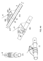
- FIGS. 4 a - d illustrate a second embodiment of the connection device according to the invention, in four different states, i.e.:
- FIG. 4 a showing the guide post prior to entry into the guide post receptacle
- FIG. 4 b showing the guide post in a first position partly inside the guide post receptacle
- FIG. 4 c showing the guide post in a second position partly inside the guide post receptacle
- FIG. 4 d showing the guide post in an installed position inside the guide post receptacle and the coupling in a connected state
- FIGS. 4 a - d containing four drawings where drawings (i) and (ii) are perspective views, drawing (iii) is a side view, and drawing (iv) is a longitudinal sectional view drawing (iii);
- FIG. 5 illustrates a third embodiment of the connection device according to the invention, containing three drawings where drawings (i) and (iii) are perspective views and drawing (ii) is a side view;
- FIG. 6 illustrates a fourth embodiment of the invention, where drawings (i) and (ii) are perspective drawings of two variants of guide elements of this embodiment, and drawings (iii) and (iv) are drawings of a third variant of a guide element in cooperation with a guide element receptacle.
- FIG. 7 illustrates a fifth embodiment of the invention, where drawings (i) and (ii) are perspective drawings of two variants of guide elements of this embodiment, and drawings (iii) and (iv) are drawings of a third variant of a guide element in cooperation with a guide element receptacle.
- FIGS. 1 a and 1 b are principle sketches illustrating an arrangement in which the connection device according to the invention may be used.
- a production vessel 1 and a shuttle tanker 2 (of which only parts are shown) are floating in water W and moored to one another in a tandem configuration by means of a pair of double hawsers 3 in a crowfoot arrangement.
- the distance between the vessels may for example be maintained by the shuttle tanker 2 keeping a constant astern pulling force, thereby keeping the hawsers taut.
- the production vessel 1 may for example be a turret moored LNG FPSO, which may weathervane freely. This arrangement is well known in the art.
- the production vessel 1 is fitted with a so-called A-frame 4 , pivotally mounted to the deck of the production vessel as indicated by the double arrow in FIG. 1 a .
- Three substantially parallel flexible pipes 5 extend between the vessels, two of which are designated for transferring LNG, whereas the third is designated for returning vaporized LNG (boil-off) from the shuttle tanker 2 to the production vessel 1 .
- These pipes may for example be corrugated stainless steel vacuum insulated CRYODYN® flexible pipes
- the flexible pipes 5 are supported by a the A-frame 4 and each pipe 5 comprises at its free end a coupling head 16 to be introduced into a respective receptacles in a pull-in and connection unit 6 on the shuttle tanker 2 .
- FIGS. 1 a and 1 b illustrate the flexible pipes 5 in such coupled and locked state, in which fluid transfer between the vessels may take place.
- Each coupling head 16 comprises a connection flange 15 , ball valve 12 and a swivel joint 10 .
- the pull-in and connection unit 6 there is one docking and connection unit for each coupling head 16 , comprising a pull-in winch, coupling head 20 with connector and ball valve and a flange 21 .
- connection device for transfer of fluids between the vessels, and the details of this connection device and the associated connection procedure will now be described in detail.
- FIGS. 2 a - c and FIG. 3 A first embodiment of the invention will now be described with reference to FIGS. 2 a - c and FIG. 3 .
- FIG. 2 a illustrates a preliminary state of a connection process, where a coupling head 16 has been pulled by a pull-in wire 8 connected to a guide post 101 , to a position near the pull-in and connection unit 6 .
- the other end of the pull-in wire 8 is connected to a conventional pull-in winch arrangement (not shown) on the shuttle tanker 2 .
- FIG. 2 b the guide post on the flexible pipe 5 has entered the pull-in and connection unit 6
- FIG. 2 c shows the connection device in a coupled and locked state, i.e. the state which is schematically illustrated by FIG. 1 a,b.
- the flexible pipe 5 is near its free end provided with a coupling head 16 comprising a ball valve housing 12 having a first flange 15 for connection to a corresponding second flange 21 on the coupling housing 20 on the shuttle tanker 2 .
- the ball valve is opened by a valve actuator 14 upon connection, which is well known in the art.
- the coupling head 16 furthermore comprises a guide post 101 , connected to the flexible pipe by a suitable clamp arrangement 104 .
- the guide post 101 comprises a head portion 102 at its outer free end; an inner base portion 105 ; and an intermediate middle neck portion 103 .
- the guide post head 102 is comparably small, preferably in this embodiment comprising a ball shape.
- the base portion 105 has a substantially rectangular and slender cross-section, its long side extending along the central axis of the flexible pipe.
- the intermediate portion 103 also has a substantially rectangular and slender cross-section towards the base portion, and the side of the intermediate portion facing the valve housing 12 is substantially straight and aligned substantially parallel with the valve housing central axis (see FIG. 3 ).
- the coupling head 16 is connected to the flexible pipe 5 by via a swivel joint 10 .
- the pull-in and connection unit 6 is pivotally connected to the shuttle tanker 2 (only immediate support structure of shuttle tanker is shown in FIG. 2 a ) via a gimbal mounting 26 a,b .
- This gimbal mounting (or, cardanic suspension) of the pull-in and connection unit 6 ensures a moment-free connection.
- the gimbal mounting structure is designed to support the external loads from the hose and connector system. This structure is thermally insulated from the sometimes cold piping system at the mounting flange of the coupling housing 20 .
- the rotational axis of the piping system are coinciding with the gimbals system axis at ambient temperature.
- the piping system is elastically arranged to allow for thermal deflections.
- the coupling housing 20 comprises the aforementioned second flange 21 , a plurality of locking claws 22 , a locking actuator 23 and activation elements 24 .
- the actuator 23 rotates the activation elements, whereby the locking claws 22 engage the first flange 15 and establishes the connection.
- the valve actuator 14 is operated, the ball valves are opened and fluids may flow from the flexible pipe 5 and into the piping 25 on the shuttle tanker.
- This valve connector may be of a type which is known in the art, for example the “Bow Connector System” developed and sold by MIB Italiana S.p.a.
- the piping 25 between the valve and the onboard storage tanks is only partially shown, as this is known in the art and not material for understanding the invention.
- the docking frame 122 Arranged on the pull-in and connection unit 6 is a docking frame 122 , in this embodiment having a pulley 126 for the pull-in wire 8 .
- the docking frame 122 comprises a guide post receptacle 123 , configured for accommodating and supporting at least a portion of the guide post 101 , as is explained in more detail below.
- the guidepost receptacle 123 is movable in the docking frame 122 between an extended position (illustrated by FIG. 2 a ) and a retracted position (illustrated by FIG. 2 c ). In the illustrated embodiment, this movement of the guide post receptacle 123 is that of reciprocation with respect to the docking frame 122 , by means of one or more actuators 130 .
- the receptacle actuators 130 may be hydraulic actuators or they may be threaded screw jacks.
- the guide post receptacle 123 comprises a hawse hole 124 —into which also the guide post is pulled—and is conveniently equipped with a pair of guide rollers 125 .
- FIG. 2 a illustrates how the shape and positioning of the guide post 101 and the fact that the pull-in wire is connected to the guide post head 102 , the direction of pull exerted on the flexible pipe 5 differs from the central axis of the flexible pipe. This ensures that a significant leverage arm is established before side loads are experienced and a righting moment is generated on the pipe and serves to align it in the final phase of to the guide post entering the guide post receptacle.
- the guide post 101 has been pulled inside the guide post receptacle 123 and locked in this position by a suitable lock arrangement, such as a pin (not shown) extending through corresponding holes 106 , 127 in the guide post and the guide post receptacle, respectively.
- a suitable lock arrangement such as a pin (not shown) extending through corresponding holes 106 , 127 in the guide post and the guide post receptacle, respectively.
- Such locking arrangement which is known in the art and need not be described further—allows the tension in the pull-in wire 8 to be relieved, as the guide post 101 in this state is connected to the guide post receptacle 123 .
- the guide post head 102 which is of a ball shape, is additionally supported by rollers 128 a,b in the receptacle 123 .
- the interior of the guide post receptacle comprises a geometry which is complementary to the guide post geometry, explained above.
- the guide post receptacle comprises a substantially rectangular, funnel-shaped opening, for accommodating the substantially rectangular and slender cross-section of the base portion 105 .
- FIG. 3 illustrates how the guide post head 102 is supported by the two rollers 128 a,b , and how the side of the intermediate portion 103 which is facing the valve housing is aligned substantially parallel with the valve housing central axis and is being supported by the lower roller 128 b .
- this feature is also particularly useful in a so-called “quick disconnect” situation, i.e. where the coupling head 16 is released by paying out or cutting the wire, without extending the slidable docking frame 122 .
- This particular shape of the guide post ensures that the coupling head in will move away from the coupling housing 20 while initially following a path approximately parallel with the central axes a-a and b-b (see FIG. 3 ), before it falls out of and away from the receptacle 123 . Therefore, a quick disconnect operation may be performed without the risk of damaging the valve flanges.
- FIG. 3 also shows how the interior of the guide post receptacle 123 comprises a shape which is complementary to the shape of the guide post, thus ensuring that the central axis a-a of the flexible pipe 5 is aligned with the central axis b-b of the coupling housing 20 .
- the two axes are coincident once the guide post is in place within the guide post receptacle.
- FIG. 3 also illustrates how the guide post head 102 —where the pull-in wire is attached—extends a distance h from the flexible pipe central axis a-a and how direction of pull by the pull-in wire deviates from the central axis a-a by an angle ⁇ .
- the double arrow M in FIG. 3 indicates that the guide post receptacle 123 is movable back and forth in the docking frame 122 , parallel to the central axis b-b.
- the two flanges 15 , 21 may be mated in a safe and controlled manner by moving the guide post receptacle 123 to its retracted position and the coupling may be made up and locked as described above.
- the two flanges 15 , 21 may be prepared for mating, in that protective covers, etc. may be removed in a controlled and safe manner.
- FIG. 2 c The made-up and locked state is illustrated by FIG. 2 c , where the movable guide post receptacle 123 has been moved (by the actuators 130 ) to a retracted position in the docking frame, whereby the flanges are connected and locked.
- FIGS. 4 a - d A second embodiment of the invention will now be described with reference to FIGS. 4 a - d .
- FIGS. 4 a - d A second embodiment of the invention will now be described with reference to FIGS. 4 a - d .
- FIGS. 4 a - d A second embodiment of the invention will now be described with reference to FIGS. 4 a - d .
- FIGS. 4 a - d A second embodiment of the invention will now be described with reference to FIGS. 4 a - d .
- FIGS. 4 a - d A second embodiment of the invention will now be described with reference to FIGS. 4 a - d .
- FIG. 4 a illustrates a preliminary state of a connection process, where the pull-in wire 8 attached to the guide post 201 has pulled the flexible pipe 5 to a position in the proximity of the pull-in and connection unit 6 .
- the guide post 201 extends a distance h from the flexible pipe central axis a-a (see drawing (iii)), and the pull-in wire 8 is attached to the guide post 201 free end, or head 202 .
- the angle of pull on the flexible pipe deviates from the central axis of the flexible pipe.
- the pull-in and connection unit 6 comprises a guide post receptacle 223 which is stationary with respect to the docking frame 222 .
- the guide post receptacle 223 may also be slidably arranged with respect to the docking frame 222 ; similar to the arrangement in the first embodiment.
- the guide post 201 and the guide post receptacle 223 comprise complementary a bell mouth shapes.
- the guide post receptacle 223 is of a non-circular shape, more precisely a substantially rectangular shape, the length of the cross-section being substantially parallel with the central axis b-b of the coupling housing 20 .
- the guide post receptacle 223 central axis d and the central axis b-b of the coupling housing 20 are non-parallel with respect to each other, i.e. having an angle ⁇ between them, where 0° ⁇ 90°. For a particular loading system, this angle is estimated based on flexible pipe and coupling system weights and stiffness. Typically, 15° ⁇ 35°.
- the guide post 201 is of a shape complementary to that of the guide post receptacle 223 , the length of the guide post cross-section being substantially parallel with the central axis a-a of the flexible pipe 5 .
- the central axis a-a of the flexible pipe is at an angle ⁇ 1 with the central axis b-b of the coupling housing 20 .
- the guide post 201 has entered the guide post receptacle 223 .
- the aforementioned rectangular shapes ensure sideways alignment of the flexible pipe 5 with respect to the coupling housing 20 , i.e. into the same vertical plane.
- the aforementioned bell mouth shapes serve to reduce the angle between the central axes a-a and b-b.
- the central axis a-a of the flexible pipe is at an angle ⁇ 2 with the central axis b-b of the coupling housing 20 , and ⁇ 2 ⁇ 1 .
- the guide post has been pulled completely into the guide post receptacle 223 , the first flange 15 and the second flange 21 have been mated, and the connection is complete.
- the guide post may preferably be locked to the guide post receptacle in this position, by means of a locking pin (not shown) or a similar locking device known in the art.
- FIG. 5 A third embodiment of the invention will now be described with reference to FIG. 5 .
- FIG. 5 contain principle sketches, only elements which are needed in order to explain the invention are shown. The skilled person will understand which ancillary components are required for a practical application, e.g. on the basis of information provided by FIGS. 1-4 and described in the foregoing.
- FIG. 5 illustrates a preliminary state of a connection process.
- the pull-in wire 8 runs through a receptacle 323 , around a pulley 326 and on to a pull-in winch (not shown).
- the skilled person will understand that the receptacle 323 is attached to, and a part of, the pull-in and connection unit 6 described above.
- the guide on the flexible pipe comprises a guide arrangement 301 attached to the flexible pipe 5 .
- the guide arrangement 301 comprises:
- the angle of pull on the flexible pipe deviates from the central axis of the flexible pipe.
- FIG. 6 A fourth embodiment of the invention will now be described with reference to FIG. 6 .
- FIG. 6 contain principle sketches, only elements which are needed in order to explain the invention are shown. The skilled person will understand which ancillary components are required for a practical application, e.g. on the basis of information provided by FIGS. 1-4 and described in the foregoing.
- the guide on the flexible pipe comprises a guide arrangement 401 attached to the flexible pipe (pipe not shown in FIG. 6 ).
- Drawing (i) shows a triangular shaped plate 401 a
- drawing (ii) shows a rectangular shaped plate 401 ′ a
- drawing (iii) shows a circular shaped plate 401 ′′ a
- the plates are connected to the pull-in wire 8 via two wire segments 401 b,c which meet at the juncture P and are attached in a spaced-apart relationship to the plate.
- FIG. 6 illustrates how the pull-in wire 8 runs through a receptacle 423 , through a guide ring 426 and on to a pull-in winch (not shown).
- the skilled person will understand that the receptacle 423 and the guide ring 426 are attached to, and a part of, the pull-in and connection unit 6 described above.
- Drawing (iv) of FIG. 6 illustrates the state when the guide arrangement 401 has been pulled completely into the receptacle 423 , the wire segments 401 b,c having exerted a righting moment on the plate 401 ′′ a attached to the flexible pipe (not shown in FIG. 6 ) and the flexible pipe thus having been aligned with the pull-in and connection unit described above.
- FIG. 7 A fifth embodiment of the invention will now be described with reference to FIG. 7 .
- FIG. 7 contain principle sketches, only elements which are needed in order to explain the invention are shown. The skilled person will understand which ancillary components are required for a practical application, e.g. on the basis of information provided by FIGS. 1-4 and described in the foregoing.
- the guide on the flexible pipe comprises a guide arrangement 501 attached to the flexible pipe (pipe not shown in FIG. 7 ).
- Drawings (i) and (ii) show triangular shaped plates 501 a , 501 ′ a , and drawing (iii) shows a circular shaped plate 501 ′′ a .
- the plates are connected to the pull-in wire 8 via three wire segments 501 b,c,d which meet at the juncture P and are attached in a triangular spaced-apart relationship to the plate.
- FIG. 7 illustrates how the pull-in wire 8 runs through a receptacle 523 , through a guide ring 526 and on to a pull-in winch (not shown).
- the skilled person will understand that the receptacle 523 and the guide ring 526 are attached to, and a part of, the pull-in and connection unit 6 described above.
- FIG. 7 illustrates the state when the guide arrangement 501 has been pulled completely into the receptacle 523 , the wire segments 501 b,c,d having exerted a righting moment on the plate 501 ′′ a attached to the flexible pipe (not shown in FIG. 6 ) and the flexible pipe thus having been aligned with the pull-in and connection unit described above.
- connection device according to the invention also may be employed in other LNG systems, such as between a sea-going vessel and an onshore plant, or between other vessels on land or at sea.
- the invention is useful also for other fluids than LNG.
- connection device is applicable for pipes of any stiffness.
Landscapes
- Engineering & Computer Science (AREA)
- General Engineering & Computer Science (AREA)
- Mechanical Engineering (AREA)
- Chemical & Material Sciences (AREA)
- Combustion & Propulsion (AREA)
- Ocean & Marine Engineering (AREA)
- Geology (AREA)
- Architecture (AREA)
- Life Sciences & Earth Sciences (AREA)
- Mining & Mineral Resources (AREA)
- General Life Sciences & Earth Sciences (AREA)
- Fluid Mechanics (AREA)
- Environmental & Geological Engineering (AREA)
- Geochemistry & Mineralogy (AREA)
- Physics & Mathematics (AREA)
- Civil Engineering (AREA)
- Structural Engineering (AREA)
- Quick-Acting Or Multi-Walled Pipe Joints (AREA)
- Filling Or Discharging Of Gas Storage Vessels (AREA)
- Details Of Connecting Devices For Male And Female Coupling (AREA)
- Loading And Unloading Of Fuel Tanks Or Ships (AREA)
- Physical Deposition Of Substances That Are Components Of Semiconductor Devices (AREA)
- Control Of Motors That Do Not Use Commutators (AREA)
- Seal Device For Vehicle (AREA)
Applications Claiming Priority (3)
| Application Number | Priority Date | Filing Date | Title |
|---|---|---|---|
| NO20092011 | 2009-05-25 | ||
| NO20092011A NO337059B1 (no) | 2009-05-25 | 2009-05-25 | Koblingsinnretning |
| PCT/NO2010/000188 WO2010137990A1 (en) | 2009-05-25 | 2010-05-25 | Coupling device |
Related Parent Applications (1)
| Application Number | Title | Priority Date | Filing Date |
|---|---|---|---|
| PCT/NO2010/000188 A-371-Of-International WO2010137990A1 (en) | 2009-05-25 | 2010-05-25 | Coupling device |
Related Child Applications (1)
| Application Number | Title | Priority Date | Filing Date |
|---|---|---|---|
| US14/713,447 Continuation US9334994B2 (en) | 2009-05-25 | 2015-05-15 | Coupling device |
Publications (2)
| Publication Number | Publication Date |
|---|---|
| US20120133122A1 US20120133122A1 (en) | 2012-05-31 |
| US9163765B2 true US9163765B2 (en) | 2015-10-20 |
Family
ID=42309685
Family Applications (2)
| Application Number | Title | Priority Date | Filing Date |
|---|---|---|---|
| US13/322,278 Active 2033-02-17 US9163765B2 (en) | 2009-05-25 | 2010-05-25 | Coupling device |
| US14/713,447 Active US9334994B2 (en) | 2009-05-25 | 2015-05-15 | Coupling device |
Family Applications After (1)
| Application Number | Title | Priority Date | Filing Date |
|---|---|---|---|
| US14/713,447 Active US9334994B2 (en) | 2009-05-25 | 2015-05-15 | Coupling device |
Country Status (13)
| Country | Link |
|---|---|
| US (2) | US9163765B2 (pt) |
| EP (1) | EP2435745B1 (pt) |
| JP (2) | JP5771606B2 (pt) |
| KR (1) | KR101661377B1 (pt) |
| CN (1) | CN102449370B (pt) |
| AU (1) | AU2010253533B2 (pt) |
| BR (1) | BRPI1012045B1 (pt) |
| CA (1) | CA2763252C (pt) |
| NO (1) | NO337059B1 (pt) |
| PL (1) | PL2435745T3 (pt) |
| RU (1) | RU2527819C2 (pt) |
| SG (1) | SG176606A1 (pt) |
| WO (1) | WO2010137990A1 (pt) |
Cited By (2)
| Publication number | Priority date | Publication date | Assignee | Title |
|---|---|---|---|---|
| CN109415110A (zh) * | 2016-07-18 | 2019-03-01 | 麦基嘉挪威公司 | 用于在公海上输送碳氢化合物的联接系统 |
| US20210053695A1 (en) * | 2016-08-20 | 2021-02-25 | Modern Technology Solutions, Inc. | Fire bomber delivery |
Families Citing this family (26)
| Publication number | Priority date | Publication date | Assignee | Title |
|---|---|---|---|---|
| NO2473769T3 (pt) * | 2009-09-03 | 2018-05-26 | ||
| FR2973771B1 (fr) | 2011-04-11 | 2015-07-17 | Fmc Technologies Sa | Systeme et procede de transfert de fluide offshore |
| CN103144742B (zh) * | 2012-11-30 | 2015-04-22 | 中海油田服务股份有限公司 | 一种海上钻井平台输送软管与供应船的连接装置 |
| FR2999522B1 (fr) * | 2012-12-18 | 2015-01-16 | Gaztransp Et Technigaz | Systeme de manutention pour conduite flexible |
| WO2014122122A1 (en) | 2013-02-05 | 2014-08-14 | Aker Pusnes As | Arrangements and a method for connection and disconnection of at least one hose carrying fluid especially lng and/or vaporized lng |
| NO336992B1 (no) * | 2013-02-05 | 2015-12-14 | Aker Pusnes As | Koblingsarrangement lastoverføring |
| EP2808294A1 (en) * | 2013-05-31 | 2014-12-03 | Shell Internationale Research Maatschappij B.V. | Loading Assembly and Emergency Disconnection Coupler for conveying a pressurized Gas between a floating Gas processing Unit and another Structure |
| WO2015055835A1 (en) | 2013-10-18 | 2015-04-23 | Shell Internationale Research Maatschappij B.V. | Loading assembly for conveying a pressurized gas stream and a switching system for use in a loading assembly |
| FR3012411B1 (fr) * | 2013-10-31 | 2016-08-05 | Gaztransport Et Technigaz | Systeme pour le transfert de fluide entre un navire et une installation, telle qu'un navire client |
| US20150159457A1 (en) * | 2013-12-11 | 2015-06-11 | Blackhawk Specialty Tools, Llc | Automated connection assembly |
| US10041310B2 (en) * | 2013-12-11 | 2018-08-07 | Blackhawk Specialty Tools, Llc | Method and apparatus for automated connection of a fluid conduit |
| NO343252B1 (en) * | 2015-04-30 | 2018-12-27 | Vetco Gray Scandinavia As | Horizontal connection arrangement |
| GB201517554D0 (en) * | 2015-10-05 | 2015-11-18 | Connector As | Riser methods and apparatuses |
| NO341918B1 (en) * | 2016-05-04 | 2018-02-19 | Cefront Tech As | Offshore loading hose coupling |
| CN106005276B (zh) * | 2016-05-19 | 2017-12-01 | 武汉船用机械有限责任公司 | 海上液货补给输送装置 |
| BR112019027274B1 (pt) * | 2017-06-23 | 2022-02-15 | Frank's International, Llc | Aparelho para conectar uma extremidade distal de um conduto de fluido a uma entrada de fluido e método para conectar uma extremidade distal de um conduto de fluido a uma entrada de fluido de uma ferramenta de cimentação ou fraturamento |
| NO343647B1 (en) | 2017-10-16 | 2019-04-23 | Apl Tech As | System and method for connecting a mooring line to a body |
| JP7190899B2 (ja) * | 2018-12-28 | 2022-12-16 | 大阪瓦斯株式会社 | 液化低温流体の荷役設備 |
| CN114072609A (zh) * | 2019-05-29 | 2022-02-18 | 索菲克股份有限公司 | 用于处理一个或更多个细长构件的系统及使用系统的方法 |
| KR102271081B1 (ko) | 2020-02-10 | 2021-06-29 | 현대중공업 주식회사 | 셔틀 탱크선의 원유 공급용 커플러 |
| KR102440146B1 (ko) * | 2020-05-26 | 2022-09-05 | 주식회사 케이씨 | 가스 용기 체결 장치 |
| NO346158B1 (en) * | 2020-06-18 | 2022-03-28 | Moray Group As | A hose transfer system and a method for coupling a coupling stab of a hose to the system |
| CN113371355B (zh) * | 2021-02-04 | 2022-08-23 | 成都国翼电子技术有限公司 | 一种六自由度的随动抱轴装置 |
| CN113864024A (zh) * | 2021-09-22 | 2021-12-31 | 隆鑫通用动力股份有限公司 | 发动机机油放油管的快速放油装置 |
| NO20220943A1 (en) * | 2022-09-01 | 2024-03-04 | Apl Norway As | Motion restrictor device and system for offshore loading |
| CN116923651B (zh) * | 2023-07-05 | 2024-03-05 | 广东工业大学 | 一种浮式生产储油装置 |
Citations (12)
| Publication number | Priority date | Publication date | Assignee | Title |
|---|---|---|---|---|
| US3434296A (en) * | 1966-10-24 | 1969-03-25 | Shell Oil Co | Method and apparatus for connecting an underwater pipeline to an offshore installation |
| SU370108A1 (ru) | 1971-10-18 | 1973-02-15 | УСТРОЙСТВО дл стыковки ШЛАНГОВЫХ СОЕДИНЕНИЙ | |
| US3924446A (en) | 1973-08-07 | 1975-12-09 | Benton F Baugh | Underwater connection apparatus |
| US4102146A (en) * | 1977-05-25 | 1978-07-25 | Sofec, Inc. | Method of and apparatus for handling hose underwater |
| US4615646A (en) | 1984-05-25 | 1986-10-07 | Shell Oil Company | Flowline connection means |
| US4842075A (en) * | 1987-06-09 | 1989-06-27 | Mobil Oil Corporation | Subsea flowline connection system |
| US5163782A (en) * | 1990-10-12 | 1992-11-17 | Petroleo Brasileiro S.A. - Petrobras | Subsea connection system and active connector utilized in said system |
| US5197822A (en) * | 1990-11-09 | 1993-03-30 | Parks James M | Emplacement of foraminous piping in non-cohesive subsoils |
| WO2001034460A1 (en) | 1999-10-27 | 2001-05-17 | Statoil Asa | A system for offshore transfer of liquefied natural gas |
| US20040011424A1 (en) | 2000-10-06 | 2004-01-22 | Bernard Dupont | System for transferring a fluid product between a carrying vessel and a shore installation |
| US6832874B2 (en) * | 2000-08-18 | 2004-12-21 | Alpha Thames Ltd. | Modular seabed processing system |
| US7025535B2 (en) * | 2002-05-07 | 2006-04-11 | Saipem S.A. | Seafloor/surface connecting installation for a submarine pipeline which is connected to a riser by means of at least one elbow pipe element that is supported by a base |
Family Cites Families (6)
| Publication number | Priority date | Publication date | Assignee | Title |
|---|---|---|---|---|
| US2922446A (en) * | 1958-04-16 | 1960-01-26 | Parsons Brinckerhoff Hall & Ma | Marine hose loader |
| US4165892A (en) * | 1977-08-12 | 1979-08-28 | Victaulic Company Of America | Coupling for releasably securing one end of a rod-like member |
| NO315194B1 (no) * | 1998-01-30 | 2003-07-28 | Navion As | Fremgangsmåte og system for eksport av LNG og kondensat fra et flytende produksjons-, lagrings- og lossefartöy |
| JP2002267074A (ja) * | 2001-03-09 | 2002-09-18 | Toyoda Gosei Co Ltd | コネクタ |
| US7610934B2 (en) * | 2003-05-05 | 2009-11-03 | Single Buoy Moorings Inc. | Hydrocarbon transfer system with a damped transfer arm |
| JP4541678B2 (ja) * | 2003-10-10 | 2010-09-08 | 株式会社関ヶ原製作所 | 搭載艇揚降装置 |
-
2009
- 2009-05-25 NO NO20092011A patent/NO337059B1/no not_active IP Right Cessation
-
2010
- 2010-05-25 EP EP10721575.8A patent/EP2435745B1/en active Active
- 2010-05-25 BR BRPI1012045 patent/BRPI1012045B1/pt active IP Right Grant
- 2010-05-25 WO PCT/NO2010/000188 patent/WO2010137990A1/en active Application Filing
- 2010-05-25 CA CA2763252A patent/CA2763252C/en active Active
- 2010-05-25 KR KR1020117031023A patent/KR101661377B1/ko active IP Right Grant
- 2010-05-25 RU RU2011150946/06A patent/RU2527819C2/ru active
- 2010-05-25 JP JP2012512990A patent/JP5771606B2/ja not_active Expired - Fee Related
- 2010-05-25 PL PL10721575T patent/PL2435745T3/pl unknown
- 2010-05-25 CN CN201080023096.3A patent/CN102449370B/zh not_active Expired - Fee Related
- 2010-05-25 AU AU2010253533A patent/AU2010253533B2/en active Active
- 2010-05-25 US US13/322,278 patent/US9163765B2/en active Active
- 2010-05-25 SG SG2011087178A patent/SG176606A1/en unknown
-
2014
- 2014-06-13 JP JP2014122093A patent/JP2014206276A/ja not_active Withdrawn
-
2015
- 2015-05-15 US US14/713,447 patent/US9334994B2/en active Active
Patent Citations (12)
| Publication number | Priority date | Publication date | Assignee | Title |
|---|---|---|---|---|
| US3434296A (en) * | 1966-10-24 | 1969-03-25 | Shell Oil Co | Method and apparatus for connecting an underwater pipeline to an offshore installation |
| SU370108A1 (ru) | 1971-10-18 | 1973-02-15 | УСТРОЙСТВО дл стыковки ШЛАНГОВЫХ СОЕДИНЕНИЙ | |
| US3924446A (en) | 1973-08-07 | 1975-12-09 | Benton F Baugh | Underwater connection apparatus |
| US4102146A (en) * | 1977-05-25 | 1978-07-25 | Sofec, Inc. | Method of and apparatus for handling hose underwater |
| US4615646A (en) | 1984-05-25 | 1986-10-07 | Shell Oil Company | Flowline connection means |
| US4842075A (en) * | 1987-06-09 | 1989-06-27 | Mobil Oil Corporation | Subsea flowline connection system |
| US5163782A (en) * | 1990-10-12 | 1992-11-17 | Petroleo Brasileiro S.A. - Petrobras | Subsea connection system and active connector utilized in said system |
| US5197822A (en) * | 1990-11-09 | 1993-03-30 | Parks James M | Emplacement of foraminous piping in non-cohesive subsoils |
| WO2001034460A1 (en) | 1999-10-27 | 2001-05-17 | Statoil Asa | A system for offshore transfer of liquefied natural gas |
| US6832874B2 (en) * | 2000-08-18 | 2004-12-21 | Alpha Thames Ltd. | Modular seabed processing system |
| US20040011424A1 (en) | 2000-10-06 | 2004-01-22 | Bernard Dupont | System for transferring a fluid product between a carrying vessel and a shore installation |
| US7025535B2 (en) * | 2002-05-07 | 2006-04-11 | Saipem S.A. | Seafloor/surface connecting installation for a submarine pipeline which is connected to a riser by means of at least one elbow pipe element that is supported by a base |
Non-Patent Citations (4)
| Title |
|---|
| English translation of Decision to Grant a Patent in counterpart Russian Patent Application No. 2011150946/06 (076532) issued Apr. 9, 2014 (4 pages). |
| International Preliminary Report on Patentability issued in PCT/NO2010/000188, mailed on Aug. 29, 2011, 7 pages. |
| International Search Report issued in PCT/NO2010/000188, mailed on Jul. 21, 2010, 2 pages. |
| Norwegian Search Report issued in NO20092011, dated Dec. 1, 2009, 1 page. |
Cited By (6)
| Publication number | Priority date | Publication date | Assignee | Title |
|---|---|---|---|---|
| CN109415110A (zh) * | 2016-07-18 | 2019-03-01 | 麦基嘉挪威公司 | 用于在公海上输送碳氢化合物的联接系统 |
| US10946938B2 (en) | 2016-07-18 | 2021-03-16 | Macgregor Norway As | Coupling system for transfer of hydrocarbons at open sea |
| US20210053695A1 (en) * | 2016-08-20 | 2021-02-25 | Modern Technology Solutions, Inc. | Fire bomber delivery |
| US20210163150A1 (en) * | 2016-08-20 | 2021-06-03 | Modern Technology Solutions, Inc. | Smart fire hose |
| US11591105B2 (en) * | 2016-08-20 | 2023-02-28 | Modern Technology Solutions, Inc. | Fire bomber delivery |
| US11702221B2 (en) * | 2016-08-20 | 2023-07-18 | Modern Technology Solutions, Inc. | Smart fire hose |
Also Published As
| Publication number | Publication date |
|---|---|
| CA2763252A1 (en) | 2010-12-02 |
| WO2010137990A1 (en) | 2010-12-02 |
| CA2763252C (en) | 2017-12-19 |
| EP2435745A1 (en) | 2012-04-04 |
| EP2435745B1 (en) | 2020-02-19 |
| NO20092011L (no) | 2010-11-26 |
| BRPI1012045A2 (pt) | 2016-05-17 |
| PL2435745T3 (pl) | 2020-07-27 |
| US20120133122A1 (en) | 2012-05-31 |
| JP2014206276A (ja) | 2014-10-30 |
| CN102449370B (zh) | 2015-11-25 |
| US20150247599A1 (en) | 2015-09-03 |
| JP5771606B2 (ja) | 2015-09-02 |
| RU2011150946A (ru) | 2013-07-10 |
| KR101661377B1 (ko) | 2016-10-10 |
| RU2527819C2 (ru) | 2014-09-10 |
| CN102449370A (zh) | 2012-05-09 |
| AU2010253533A1 (en) | 2011-12-15 |
| NO337059B1 (no) | 2016-01-11 |
| AU2010253533B2 (en) | 2015-08-06 |
| KR20120057586A (ko) | 2012-06-05 |
| JP2012528287A (ja) | 2012-11-12 |
| US9334994B2 (en) | 2016-05-10 |
| BRPI1012045B1 (pt) | 2019-12-10 |
| SG176606A1 (en) | 2012-01-30 |
Similar Documents
| Publication | Publication Date | Title |
|---|---|---|
| US9334994B2 (en) | Coupling device | |
| US7066219B2 (en) | Hydrocarbon fluid transfer system | |
| EP1796958B1 (en) | Offshore vessel mooring and riser inboarding system | |
| US6851994B2 (en) | Disconnectable mooring system and LNG transfer system and method | |
| US9988860B2 (en) | Method and apparatus for elevating the tapered stress joint or flex joint of an SCR above the water | |
| US8418639B2 (en) | Mooring system for a vessel | |
| US7997947B2 (en) | Deep water hydrocarbon transfer system | |
| KR20110119764A (ko) | 유체 제품을 운반하기 위한 시스템 및 방법 | |
| US20210188402A1 (en) | System and method for connecting a mooring line to a body | |
| EP3484762B1 (en) | Coupling system for transfer of hydrocarbons at open sea | |
| US10087067B2 (en) | Fluid transfer apparatus | |
| EP3154852B1 (en) | A tensile overload protection system for offloading systems | |
| WO2016135487A1 (en) | Fluid transfer system and method for carrying out fluid transfer | |
| NO346025B1 (en) | An emergency release system for a fluid transfer system transferring fluids from a supply facility to a receiving facility and a method of using same |
Legal Events
| Date | Code | Title | Description |
|---|---|---|---|
| AS | Assignment |
Owner name: AKER PUSNES AS, NORWAY Free format text: ASSIGNMENT OF ASSIGNORS INTEREST;ASSIGNORS:HOVIK, JON;VAN DER WOUDE, RIENTS;OYA, BIRGER;AND OTHERS;REEL/FRAME:027559/0222 Effective date: 20111221 |
|
| FEPP | Fee payment procedure |
Free format text: PAYOR NUMBER ASSIGNED (ORIGINAL EVENT CODE: ASPN); ENTITY STATUS OF PATENT OWNER: LARGE ENTITY |
|
| STCF | Information on status: patent grant |
Free format text: PATENTED CASE |
|
| AS | Assignment |
Owner name: MACGREGOR NORWAY AS, NORWAY Free format text: MERGER AND CHANGE OF NAME;ASSIGNORS:AKER PUSNES AS;MACGREGOR PUSNES AS;REEL/FRAME:038901/0347 Effective date: 20160530 |
|
| MAFP | Maintenance fee payment |
Free format text: PAYMENT OF MAINTENANCE FEE, 4TH YEAR, LARGE ENTITY (ORIGINAL EVENT CODE: M1551); ENTITY STATUS OF PATENT OWNER: LARGE ENTITY Year of fee payment: 4 |
|
| MAFP | Maintenance fee payment |
Free format text: PAYMENT OF MAINTENANCE FEE, 8TH YEAR, LARGE ENTITY (ORIGINAL EVENT CODE: M1552); ENTITY STATUS OF PATENT OWNER: LARGE ENTITY Year of fee payment: 8 |