US9134182B2 - Measurement apparatus and method, tomography apparatus and method - Google Patents
Measurement apparatus and method, tomography apparatus and method Download PDFInfo
- Publication number
- US9134182B2 US9134182B2 US13/894,065 US201313894065A US9134182B2 US 9134182 B2 US9134182 B2 US 9134182B2 US 201313894065 A US201313894065 A US 201313894065A US 9134182 B2 US9134182 B2 US 9134182B2
- Authority
- US
- United States
- Prior art keywords
- region
- information
- relative position
- unit
- reflecting surface
- Prior art date
- Legal status (The legal status is an assumption and is not a legal conclusion. Google has not performed a legal analysis and makes no representation as to the accuracy of the status listed.)
- Expired - Fee Related, expires
Links
- 238000005259 measurement Methods 0.000 title claims abstract description 96
- 238000000034 method Methods 0.000 title claims description 95
- 238000003325 tomography Methods 0.000 title claims description 6
- 238000001514 detection method Methods 0.000 claims abstract description 64
- 230000008569 process Effects 0.000 claims description 46
- 230000015572 biosynthetic process Effects 0.000 claims description 32
- 238000000691 measurement method Methods 0.000 claims description 10
- 230000003287 optical effect Effects 0.000 description 58
- 230000005284 excitation Effects 0.000 description 18
- 239000000523 sample Substances 0.000 description 17
- 230000008859 change Effects 0.000 description 15
- 230000000704 physical effect Effects 0.000 description 11
- 238000012545 processing Methods 0.000 description 9
- 239000010408 film Substances 0.000 description 7
- 230000004048 modification Effects 0.000 description 7
- 238000012986 modification Methods 0.000 description 7
- 230000006870 function Effects 0.000 description 6
- 239000004065 semiconductor Substances 0.000 description 6
- 230000003247 decreasing effect Effects 0.000 description 5
- 230000005684 electric field Effects 0.000 description 5
- 238000004611 spectroscopical analysis Methods 0.000 description 5
- 239000013078 crystal Substances 0.000 description 4
- 239000000463 material Substances 0.000 description 4
- 239000000758 substrate Substances 0.000 description 4
- 230000005540 biological transmission Effects 0.000 description 3
- 238000004891 communication Methods 0.000 description 3
- 238000009434 installation Methods 0.000 description 3
- 230000005693 optoelectronics Effects 0.000 description 3
- 230000010287 polarization Effects 0.000 description 3
- 229920005989 resin Polymers 0.000 description 3
- 239000011347 resin Substances 0.000 description 3
- 239000000126 substance Substances 0.000 description 3
- 229910000530 Gallium indium arsenide Inorganic materials 0.000 description 2
- 230000009102 absorption Effects 0.000 description 2
- 238000010521 absorption reaction Methods 0.000 description 2
- 230000008901 benefit Effects 0.000 description 2
- 238000006243 chemical reaction Methods 0.000 description 2
- 238000005229 chemical vapour deposition Methods 0.000 description 2
- 230000000694 effects Effects 0.000 description 2
- PCHJSUWPFVWCPO-UHFFFAOYSA-N gold Chemical compound [Au] PCHJSUWPFVWCPO-UHFFFAOYSA-N 0.000 description 2
- 229910052737 gold Inorganic materials 0.000 description 2
- 239000010931 gold Substances 0.000 description 2
- 230000001678 irradiating effect Effects 0.000 description 2
- 238000012544 monitoring process Methods 0.000 description 2
- 230000000149 penetrating effect Effects 0.000 description 2
- -1 polyethylene Polymers 0.000 description 2
- 230000035945 sensitivity Effects 0.000 description 2
- 229910052710 silicon Inorganic materials 0.000 description 2
- 239000010703 silicon Substances 0.000 description 2
- JBRZTFJDHDCESZ-UHFFFAOYSA-N AsGa Chemical compound [As]#[Ga] JBRZTFJDHDCESZ-UHFFFAOYSA-N 0.000 description 1
- 229920000089 Cyclic olefin copolymer Polymers 0.000 description 1
- 229910001218 Gallium arsenide Inorganic materials 0.000 description 1
- 239000004698 Polyethylene Substances 0.000 description 1
- KXNLCSXBJCPWGL-UHFFFAOYSA-N [Ga].[As].[In] Chemical compound [Ga].[As].[In] KXNLCSXBJCPWGL-UHFFFAOYSA-N 0.000 description 1
- 238000004458 analytical method Methods 0.000 description 1
- 239000000969 carrier Substances 0.000 description 1
- 238000012937 correction Methods 0.000 description 1
- 230000001419 dependent effect Effects 0.000 description 1
- 238000010586 diagram Methods 0.000 description 1
- 229910003460 diamond Inorganic materials 0.000 description 1
- 239000010432 diamond Substances 0.000 description 1
- 239000000835 fiber Substances 0.000 description 1
- 238000003384 imaging method Methods 0.000 description 1
- 238000007689 inspection Methods 0.000 description 1
- 238000011835 investigation Methods 0.000 description 1
- 230000007246 mechanism Effects 0.000 description 1
- 229920000573 polyethylene Polymers 0.000 description 1
- 229920001343 polytetrafluoroethylene Polymers 0.000 description 1
- 239000004810 polytetrafluoroethylene Substances 0.000 description 1
- 230000001902 propagating effect Effects 0.000 description 1
- 238000005070 sampling Methods 0.000 description 1
- 239000007779 soft material Substances 0.000 description 1
- 238000001228 spectrum Methods 0.000 description 1
- TXEYQDLBPFQVAA-UHFFFAOYSA-N tetrafluoromethane Chemical compound FC(F)(F)F TXEYQDLBPFQVAA-UHFFFAOYSA-N 0.000 description 1
- 239000010409 thin film Substances 0.000 description 1
- 230000007704 transition Effects 0.000 description 1
Images


Classifications
-
- G—PHYSICS
- G01—MEASURING; TESTING
- G01J—MEASUREMENT OF INTENSITY, VELOCITY, SPECTRAL CONTENT, POLARISATION, PHASE OR PULSE CHARACTERISTICS OF INFRARED, VISIBLE OR ULTRAVIOLET LIGHT; COLORIMETRY; RADIATION PYROMETRY
- G01J5/00—Radiation pyrometry, e.g. infrared or optical thermometry
- G01J5/02—Constructional details
- G01J5/0205—Mechanical elements; Supports for optical elements
-
- G—PHYSICS
- G01—MEASURING; TESTING
- G01J—MEASUREMENT OF INTENSITY, VELOCITY, SPECTRAL CONTENT, POLARISATION, PHASE OR PULSE CHARACTERISTICS OF INFRARED, VISIBLE OR ULTRAVIOLET LIGHT; COLORIMETRY; RADIATION PYROMETRY
- G01J3/00—Spectrometry; Spectrophotometry; Monochromators; Measuring colours
- G01J3/28—Investigating the spectrum
- G01J3/42—Absorption spectrometry; Double beam spectrometry; Flicker spectrometry; Reflection spectrometry
-
- G—PHYSICS
- G01—MEASURING; TESTING
- G01N—INVESTIGATING OR ANALYSING MATERIALS BY DETERMINING THEIR CHEMICAL OR PHYSICAL PROPERTIES
- G01N21/00—Investigating or analysing materials by the use of optical means, i.e. using sub-millimetre waves, infrared, visible or ultraviolet light
- G01N21/17—Systems in which incident light is modified in accordance with the properties of the material investigated
- G01N21/25—Colour; Spectral properties, i.e. comparison of effect of material on the light at two or more different wavelengths or wavelength bands
- G01N21/31—Investigating relative effect of material at wavelengths characteristic of specific elements or molecules, e.g. atomic absorption spectrometry
- G01N21/35—Investigating relative effect of material at wavelengths characteristic of specific elements or molecules, e.g. atomic absorption spectrometry using infrared light
- G01N21/3581—Investigating relative effect of material at wavelengths characteristic of specific elements or molecules, e.g. atomic absorption spectrometry using infrared light using far infrared light; using Terahertz radiation
-
- G—PHYSICS
- G01—MEASURING; TESTING
- G01N—INVESTIGATING OR ANALYSING MATERIALS BY DETERMINING THEIR CHEMICAL OR PHYSICAL PROPERTIES
- G01N21/00—Investigating or analysing materials by the use of optical means, i.e. using sub-millimetre waves, infrared, visible or ultraviolet light
- G01N21/17—Systems in which incident light is modified in accordance with the properties of the material investigated
- G01N21/47—Scattering, i.e. diffuse reflection
- G01N21/4795—Scattering, i.e. diffuse reflection spatially resolved investigating of object in scattering medium
-
- G—PHYSICS
- G01—MEASURING; TESTING
- G01N—INVESTIGATING OR ANALYSING MATERIALS BY DETERMINING THEIR CHEMICAL OR PHYSICAL PROPERTIES
- G01N21/00—Investigating or analysing materials by the use of optical means, i.e. using sub-millimetre waves, infrared, visible or ultraviolet light
- G01N21/17—Systems in which incident light is modified in accordance with the properties of the material investigated
- G01N21/55—Specular reflectivity
Definitions
- the present invention relates to a measurement apparatus and a method each using an electromagnetic wave.
- the present inventions also relates to tomography apparatus and method.
- Terahertz waves are typically electromagnetic waves containing components within a frequency band between 0.03 THz and 30 THz. Many characteristic absorptions originated from structures and states of various substances, such as biomolecules, are seen in such a frequency band. By using the characteristic, an inspection technique to non-destructively analyze or identify substances has been developed. Also, application to a safer imaging technique using, instead of X-rays, and application to a high-speed communication technique have been proposed. Further, application to a tomography apparatus which visualizes inside of an object by using, for example, terahertz waves reflected by a refractive index interface inside the object, has been attracting an attention. By using this apparatus, it is expected that the structure inside the object can be visualized at the depth of about several 100 ⁇ m to about several 10 mm by taking advantage of the penetrating characteristic of terahertz waves.
- Japanese Patent No. 4,046,158 discloses an example which measures thicknesses of an object based on a time interval between a plurality of terahertz wave pulses reflected by a plurality of interfaces of the object.
- the accuracy of the measured time interval between the terahertz wave pulses is important. It has so far been considered that the time interval between terahertz wave pulses is greatly dependent on the interval between the interfaces of the object. However, according to the investigation of the present inventors, it is found that, in an apparatus configuration in which a terahertz wave pulse is collected and irradiated to an object, the time interval between terahertz wave pulses is also changed in dependence upon the position of the object arranged in the propagation path of the terahertz wave.
- Japanese Patent No. 4,046,158 does not show detailed descriptions cocnering an adjustment of the relative positional relationship of the plurality of interfaces of the object with respect to the optical system (also referred to as a convergence unit in this specification) for collecting a terahertz wave to the object. Therefore, a measurement result which is different from the interval between the actual interfaces may be output depending on the relative positional relationship between the object and the convergence unit. That is, the reliability of measurement accuracy may be lowered. Also, in a measurement method in which an electromagnetic wave irradiated to the object is continuous wave (CW), despite that a the used conception is not the same as described in Japanese Patent No. 4,046,158, the possibility of lowering the reliability of measurement accuracy can be pointed out.
- CW continuous wave
- a measurement apparatus includes a convergence unit for converging the electromagnetic wave to the object; a detection unit for detecting electromagnetic waves from the object; and an adjustment unit for adjusting a relative position between the object and the convergence position set by the convergence unit in a detecting region selected by using interval information about an interval between a first electromagnetic wave from the first reflecting surface and a second electromagnetic wave from the second reflecting surface, the first and second electromagnetic waves being acquired by using a detection result of the detection unit, in which the detecting region is a region in which a measurement position of the object at the time of detecting electromagnetic waves from the object is determined based on relative position information selected from and by using a plurality of pieces of information on the relative position corresponding to the interval information.
- a detecting region in which measurement is performed is uniquely obtained by using the relative position between the object and the convergence position where an electromagnetic wave converged by the convergence unit, and by using the interval information about the interval between a plurality of electromagnetic waves respectively reflected by a plurality of reflecting portions of the object. Further, at the time of actually performing the measurement, the relative position is adjusted so that the portion of the object, which portion is to be measured, is included in the detecting region. Thereby, the positional relationship between the object and the convergence unit is stabilized, and hence the reliability of measurement accuracy is improved.
- FIG. 1A and FIG. 1B are views each illustrating a schematic configuration of an apparatus of exemplary embodiment 1.
- FIG. 2A and FIG. 2B are views describing a modification of the apparatus of exemplary embodiment 1.
- FIG. 3A , FIG. 3B and FIG. 3C are views describing a detecting region of the present invention and a method for obtaining the detecting region.
- FIG. 4 is a view describing an installation form of an object of exemplary embodiment 2.
- FIG. 5A and FIG. 5B are views describing results of adjustment of an object in the detecting region in exemplary embodiments 1 and 2.
- FIG. 6 is a flow chart describing a measurement method of the apparatus of exemplary embodiment 1.
- FIG. 7A and FIG. 7B are views illustrating a schematic configuration of an apparatus of exemplary embodiment 3.
- FIG. 8A and FIG. 8B are views describing an operation of the apparatus of exemplary embodiment 3.
- FIG. 9 is a flow chart describing a measurement method of the apparatus of exemplary embodiment 3.
- FIG. 10 is a view illustrating a schematic configuration of an apparatus of exemplary embodiment 4.
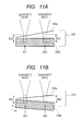
- FIG. 11A and FIG. 11B are views describing an operation of the apparatus of exemplary embodiment 4.
- FIG. 12 is a flow chart describing a measurement method of the apparatus of exemplary embodiment 4.
- FIG. 13 is a view illustrating a schematic configuration of an apparatus of exemplary embodiment 5.
- FIG. 14A and FIG. 14B are views describing an operation of the apparatus of exemplary embodiment 5.
- FIG. 15 is a flow chart describing a measurement method of the apparatus of exemplary embodiment 5.
- FIG. 16 is a view describing a result of processing of a region designation unit of example 1.
- the electromagnetic waves from the respective interfaces such as terahertz wave pulses
- the interval between the interfaces of the object can be reflected in the interval information of the electromagnetic waves, such as a time interval between terahertz wave pulses, from the plurality of interfaces. Therefore, it is important for the present invention that the reflecting portion and the interface of the object to be measured are stably adjusted in the collimated propagation region of the electromagnetic wave. The same can be said in cases where an electromagnetic wave other than a terahertz wave or a continuous wave which is not a pulse wave is used.
- electromagnetic waves from the respective interfaces of the object are detected by using an interference technique which measures interference waves by moving a reference surface (such as a movable mirror), and the interval information about the distance between the interfaces is acquired from the correspondence relationship between the amount of movement of the reference surface and the detected intensity of the electromagnetic waves.
- the interval information is acquired at each of adjusted relative positions, and the relative positions is designated to be adjusted to a position at which the value of the interval information is stabilized.
- the principle of the present invention will be described by taking, as an example, a form in which time waveforms of a plurality of electromagnetic wave pulses respectively reflected from reflecting portions of an object are acquired.
- the reliability of measurement accuracy can be improved in such a manner that the interfaces of the object to be measured are surely arranged in the collimated propagation region (wave-optically corresponding to the depth of focus) of an electromagnetic wave used for the measurement.
- a detecting region is set in the collimated propagation region of the electromagnetic wave, and the interfaces of the object are arranged in the detecting region.
- the detecting region is the collimated propagation region itself, and also a case where the detecting region is a part of the collimated propagation region.
- the object has a plurality of reflecting portions, such as a front surface, a rear surface, and a refractive index interface in the object
- a plurality of electromagnetic wave pulses are detected from the object at the time when an electromagnetic wave pulse is irradiated to the object.
- the detecting region of the present invention is determined by monitoring the time interval between electromagnetic wave pulses resulting from the reflection at the plurality of reflecting portions of the object at the time when the plurality of reflecting portions are moved, for example, in a range from the collecting process region to the collimated propagation region.
- a region in which the time interval between the electromagnetic wave pulses from the reflecting portions to be measured is not changed is defined as the detecting region. Further, by adjusting the relative position between the object and the convergence position set by the convergence unit, the interfaces of the object to be measured can be surely arranged in the detecting region included in the collimated propagation region of the electromagnetic wave used for the measurement.
- the electromagnetic wave pulse used in the present invention may have a certain penetrating characteristic.
- a terahertz wave pulse can be preferably used.
- the terahertz wave pulse has an arbitrary frequency band in the range of 0.03 THz or more to 30 THz or less. Many characteristic absorptions originating from structures and states of various substances, such as biomolecules, are appeared in this frequency band.
- a microscope using a confocal optical system As an exemplary technique in which an object is arranged in the collimated propagation region of an electromagnetic wave, there is known a microscope using a confocal optical system.
- the microscope using a confocal optical system is configured such that a signal from the focal point of the electromagnetic wave (corresponding to the collimated propagation region in this specification) is extracted by a pinhole or the like, and thereby the resolution in the depth direction is improved.
- a tomographic image is formed by moving the focal point in the depth direction of an object and detecting changes in the signal in association with the movement of the focal point.
- the present invention is different from the microscope using the confocal optical system in that a tomographic image is formed by detecting a plurality of electromagnetic waves resulting from reflection caused in the inside of the collimated propagation region.
- signals from the collimated propagation region are averaged to be detected as a signal from one pixel, while, in the present invention, the collimated propagation region is divided into a plurality of pixels, and a signal of each of the pixels is detected.
- the electromagnetic wave used in the technique of the microscope using the confocal optical system is light near the visible region, and it has, for example, a wavelength which is smaller by several orders of magnitude than the wavelength of a terahertz wave.
- the collimated propagation region defined in this specification is handled as almost a point therein.
- the microscope using the confocal optical system moves the focal point with respect to the inside of the object, and hence it does not have the concept that, as in the present invention, the object is moved in the collimated propagation region corresponding to the focal point.
- the internal structure of the object is measured in a detecting region included in the collimated propagation region, and hence the arrangement relationship about the object in the collimated propagation region is important. This importance does not exist in the technique of the microscope using the conventional confocal optical system.
- the technique of the microscope using the confocal optical system is technically different from the spirit of the invention.
- a time waveform acquisition apparatus and method which acquire a time waveform of a terahertz wave pulse used as the electromagnetic wave
- a time waveform acquisition apparatus and method which acquire a time waveform of a terahertz wave pulse used as the electromagnetic wave
- an apparatus and method which accurately acquire terahertz wave pulses from an object having a plurality of reflecting interfaces, will be described by using a principle of an apparatus (THz-TDS apparatus, and THz-Time Domain Spectroscopy apparatus) that measures terahertz waves in the time domain.
- FIG. 1A is a view illustrating a schematic configuration of an apparatus of exemplary embodiment 1.
- the present invention is described mainly based on the configuration illustrated in FIG. 1A , but configurations illustrated in FIG. 1B , FIG. 2A and FIG. 2B , as will be described below, can be used by being suitably combined with each other.
- the apparatus at least includes, as portions configured to handle a terahertz wave pulse, the followings: a terahertz wave pulse generation unit 101 for irradiating a terahertz wave pulse to an object 109 ; a convergence unit 105 for converging, to the object 109 , the terahertz wave pulse irradiated from the generation unit 101 ; and a detection unit 102 for detecting terahertz wave pulses from the object 109 .
- the convergence unit 105 is configured by four parabolic mirrors M 4 to M 7 .
- the apparatus includes, as portions configured to acquire a time waveform of a terahertz wave pulse, at least the followings: a light source 103 configured to output excitation light for generation and detection of a terahertz wave pulse; a delay optical unit 104 configured to adjust the length of an optical path of excitation light L 2 propagating from the light source 103 to the detection unit 102 ; and a waveform acquisition unit 106 configured to acquire a time waveform of terahertz wave pulses from the object 109 by referring to a change in the optical path length of the delay optical unit 104 and an output (detection result) of the detection unit 102 .
- the apparatus includes, as a portion by which an interface of an object to be measured is arranged, at least the following: an adjustment unit 108 for adjusting the relative position between the object 109 and the convergence unit 105 in the detecting region.
- an adjustment unit 108 for adjusting the relative position between the object 109 and the convergence unit 105 in the detecting region.
- the adjustment unit 108 can adjust the relative position between the object and the convergence position set by the convergence unit 105 .
- the adjustment unit 108 adjusts the relative position between the object 109 and the convergence unit 105 in a detecting region which is selected by using time information about a time interval between a plurality of electromagnetic wave pulses from the object.
- This detecting region is a region where, when the electromagnetic wave pulses from the object are detected, the measurement position of the object is determined based on position information selected from and by using a plurality of pieces of position information of the object corresponding to the time information.
- the apparatus includes a region designation unit 107 configured to determine a detecting region by referring to a plurality of sets of time waveform information acquired by the waveform acquisition unit 106 at relative positions between the object 109 and the convergence unit 105 .
- the region designation unit acquires a plurality of pieces of time information of the detected electromagnetic wave pulses and determines the detecting region from the plurality of pieces of time information.
- the apparatus includes a memory 110 configured to store a plurality of sets of the relative position and the time waveform information acquired at the relative position.
- the region designation unit 107 and the memory 110 are replaced, as illustrated in FIG. 1B , by a database 111 stored in a memory for storing beforehand the information about the detecting region.
- a beam shape of a terahertz wave pulse is stored in correspondence with a relative position. Otherwise, a predetermined object 109 is assumed, and a plurality of sets of a relative position between the object 109 and the convergence unit 105 and time waveform information acquired by the waveform acquisition unit 106 at the relative position therefor can be stored in the database 111 . In this way, the information used for specifying the detecting region of the apparatus is stored in the database 111 .
- the detecting region is determined according to a form of the object 109 , by referring to the database 111 provided beforehand in the apparatus.
- the detecting region is determined by measuring, at an arbitrary time, the relative position between the object 109 and the convergence unit 105 , and information on a time interval between pulses from a plurality of reflecting portions of the object 109 . Therefore, it is possible to easily perform measurement of the object 109 having various forms and properties, and hence the flexibility of the apparatus and method is improved.
- each of the units will be described in detail. Note that, for convenience of description, the present invention is described on the assumption that the object 109 has a first reflecting surface 109 a and a second reflecting surface 109 b .
- One of the two reflecting portions may be a reflecting portion on the surface of the object, of otherwise both the two reflecting portions may be in the inside of the object.
- the object may have two or more reflecting portions.
- a terahertz wave pulse can be generated in the generation unit 101 by using instantaneous current.
- an electric field is applied to an element (also referred to as a photoconductive element in this specification) having an antenna pattern of a metallic electrode formed on a semiconductor thin film
- excitation light is irradiated to the element, so as to generate a terahertz wave pulse.
- a PIN diode structure can be applied for generating a terahertz wave pulse.
- a terahertz wave can be generated also due to polarization which is caused in the crystal by irradiation of excitation light.
- a method using the interband transition of carriers can also be applied.
- Any form of the generation unit 101 can be used as long as it can achieve the purpose of irradiating a terahertz wave pulse to the object 109 .
- a change in the electric field intensity of a terahertz wave pulse can be detected by being converted into a change in current output from an element.
- a current corresponding to the electric field intensity of the terahertz wave pulse is detected based on a change in the photoconductivity of the element at the time when excitation light is irradiated to the element.
- a polarization splitter and an electro-optic crystal can be used.
- a magnetic field is detected by using magneto optic effect, a polarization splitter and a magneto-optic crystal can be used.
- Any form of the detection unit 102 can be used as long as it can achieve the purpose of detecting the intensity of a terahertz wave pulse from the object 109 at the time when excitation light is irradiated to the object.
- the detection unit 102 is located at the position where the terahertz wave pulse reflected by the object 109 can be detected, but the arrangement of the detection unit 102 is not limited to this. As will be described below, it is only necessary to detect terahertz wave pulses from the first reflecting surface 109 a and the second reflecting surface 109 b of the object 109 , and hence the detection unit 102 can also be arranged at a position where terahertz wave pulses transmitted through the object 109 can be detected. At this time, the detection unit 102 detects a terahertz wave pulse from each of the reflecting portions, which pulse is subjected to multiple reflection in the object 109 .
- the convergence unit 105 shapes the beam shape of the terahertz wave pulse generated in the generation unit 101 , and converges the terahertz wave pulse to the object 109 . Also, the convergence unit 105 makes the terahertz wave pulses from the object 109 incident on the detection unit 102 . In the form of FIG. 1 , the convergence unit 105 collects the terahertz wave pulse at one point on the object 109 by using the parabolic mirrors M 4 and M 5 , and also collects the terahertz wave pulses from the object 109 by using the parabolic mirrors M 6 and M 7 so as to make the collected terahertz wave pulses incident on the detection unit 102 .
- the form to converge the terahertz wave pulse is not limited to the form to collect light at one point, and, for example, the beam shape of the terahertz wave pulse may also be shaped into a strip shape, so as to be converged to the object 109 .
- a transmission type optical element such as a lens, can also be used.
- FIG. 2A and FIG. 2B are views each illustrating a schematic configuration of a time waveform acquisition apparatus including a modification of the convergence unit 105 .
- the convergence unit 105 is configured by parabolic mirrors M 5 , M 6 and M 7 and a beam splitter BS 2 .
- a terahertz wave pulse generated by the generation unit 101 is converged to the object 109 via the parabolic mirror M 5 , the beam splitter BS 2 and the parabolic mirror M 6 .
- the terahertz wave pulse reflected by the object 109 is made incident on the detection unit 102 via the parabolic mirror M 6 , the beam splitter BS 2 , and the parabolic mirror M 7 .
- the terahertz wave pulse can be made incident substantially perpendicularly to the object 109 .
- the apparatus can omit the optical length correction processing which is necessary at the time when a terahertz wave pulse is made incident obliquely to the object 109 .
- the convergence unit 105 is configured by the parabolic mirror M 5 and M 6 .
- a terahertz wave pulse generated by a generation/detection unit 201 is converged to the object 109 via the parabolic mirror M 5 and M 6 .
- the terahertz wave pulse reflected by the object 109 is again made incident on the generation/detection unit 201 via the parabolic mirror M 6 and M 5 .
- the generation/detection unit 201 performs both generation and detection of a terahertz wave pulse.
- the generation/detection unit 201 is an integrated element of a portion for generating a terahertz wave pulse and a portion for detecting a terahertz wave pulse.
- the portions for generating and detecting a terahertz wave pulse are arranged at an interval not larger than the effective wavelength of the terahertz wave pulse made incident on the generation/detection unit 201 .
- a terahertz wave pulse is generated and detected from and at the same place.
- a same element can perform both the generation and detection functions.
- a configuration of a transceiver can be realized by using a photoconductive element. With such configuration, a terahertz wave pulse propagates along substantially the same optical path, and hence the space for passage of the terahertz wave pulse can be saved, so that the size of the apparatus can be expected to be reduced.
- the light source 103 supplies excitation light to the generation unit 101 and the detection unit 102 .
- the light source 103 outputs ultrashort-pulsed laser light.
- the ultrashort-pulsed laser light output from the light source 103 has a pulse width of several 10 femtoseconds.
- excitation light output from the light source 103 is branched by a beam splitter BS to L 1 (also referred to as pump light in this specification) and L 2 (also referred to as probe light in this specification).
- the pump light L 1 is made incident on the generation unit 101 through a mirror M 1 and a focusing lens LE 1 .
- the pump light L 1 is used for generating of a terahertz wave pulse in the generation unit 101 .
- the probe light L 2 is made incident on the detection unit 102 through a mirror M 2 , the delay optical unit 104 , the mirror M 3 , and a focusing lens LE 2 .
- the probe light L 2 is used as sample light for detecting a time waveform of a terahertz wave pulse in the detection unit 102 .
- the wavelength of excitation light output from the light source 103 is changed by the drive wavelength of the generation unit 101 and the detection unit 102 .
- a wavelength conversion element for changing the wavelength of the excitation light may also be provided, as required, in the middle of the propagation path of the pump light L 1 and the probe light L 2 .
- Various characteristics, such as the wavelength and pulse width of excitation light output from the light source 103 , and the laser repetition frequency, are suitably selected based on the specification required for the apparatus.
- the delay optical unit 104 is a portion configured to adjust the optical path length difference between the pump light L 1 serving as excitation light, and the probe light L 2 .
- the time waveform of a terahertz wave pulse is acquired by using the principle of terahertz wave time-domain spectroscopy (THz—Time Domain Spectroscopy apparatus).
- THz Time Domain Spectroscopy apparatus
- the apparatus measures a terahertz wave pulse by performing sampling with the probe light L 2 in such a manner that the output of the detection unit 102 is plotted each time when the optical path length difference between the pump light L 1 and the probe light L 2 is changed by a predetermined amount.
- the method for adjusting the optical path length in the delay optical unit 104 includes a method for directly adjusting the optical path length of the excitation light, and a method for adjusting the effective optical path length of the excitation light.
- the method for directly adjusting the optical path length of the excitation light includes a method that uses a folded optical system for folding the excitation light and a movable unit for moving the folded optical system in the direction in which the excitation light is folded. Otherwise, a rotatable optical system may also be applied as the movable unit. In this case, the folded optical system is moved along the direction of rotation of the movable unit.
- the light source 103 which two laser sources, in which the repetition frequency of each of the laser sources is changed, may be used as the light source 103 , so as to respectively output the pump light L 1 and the probe light L 2 .
- the repetition frequency is different between the laser sources
- the time difference between the pump light L 1 and the probe light L 2 is modulated, and the optical path length difference between the pump light L 1 and the probe light L 2 is converted based on the change in this time difference.
- the method for adjusting the effective optical path length includes a method for changing the time constant of the optical path length along which the excitation light propagates.
- the delay optical unit 104 is configured to be able to adjust optical path length difference between the pump light L 1 and the probe light L 2 .
- the delay unit is configured to adjust a difference between the generation time and the detection time of an electromagnetic wave, and it is not necessarily necessary that the delay unit is an optical unit.
- the waveform acquisition unit 106 is a portion which forms a time waveform of terahertz wave pulses from the object 109 by using the terahertz wave time-domain spectroscopy and by referring to the output of the detection unit 102 , and the optical path length difference between the pump light L 1 and the probe light L 2 , which difference being adjusted in the delay optical unit 104 .
- the time waveform formed by the waveform acquisition unit 106 includes at least, as shown in FIG. 3B , a primary pulse 305 from the first reflecting surface 109 a , and a secondary pulse 306 from the second reflecting surface 109 b .
- the time interval ⁇ t between the primary pulse 305 and the secondary pulse 306 is a value including at least the information on the optical length of the region sandwiched between the first reflecting surface 109 a and the second reflecting surface 109 b.
- the adjustment unit 108 is a portion by which the relative position between the object 109 and the convergence unit 105 is adjusted to a detecting region.
- the apparatus of FIG. 1A is configured in a form in which the adjustment unit 108 is installed on the side of the object 109 to move the object 109 , but the configuration of the apparatus is not limited to this. It is only necessary that the adjustment unit 108 is configured to enable the relative positional distance between the object 109 and the convergence unit 105 to be changed. Therefore, the adjustment unit 108 may otherwise be configured as a portion which moves the converging position of the terahertz wave pulse by integrally moving the generation unit 101 , the detection unit 102 , and the convergence unit 105 .
- the adjustment unit 108 may be configured as a mechanism which adjusts the relative position between the object 109 and a part of the optical elements of the convergence unit 105 .
- the converging position of the terahertz wave pulse can be changed in relation to the position of the lens.
- the converging position of the terahertz wave pulse can be changed by adjusting the reflection angle of the mirror.
- the propagation beam shape of the terahertz wave is divided into a region which ranges from the focusing device 301 to the converging position of the terahertz wave (and which is referred to as a collecting process region 302 in this specification), and a region in which the converged terahertz wave propagates in a collimated manner (and which is referred to as a collimated propagation region 303 in this specification).
- the collimated propagation region 303 wave-optically corresponds to the depth of focus, and it can be regarded as a convergence position in the present invention.
- the detecting region defined by the apparatus is a region in the collimated propagation region 303 .
- the detecting region is the same as the collimated propagation region 303 .
- the detecting region is a region including at least the first reflecting surface 109 a and the second reflecting surface 109 b . since the detecting region is the same as the collimated propagation region 303 itself or included in the collimated propagation region 303 , the first reflecting surface 109 a and the second reflecting surface 109 b can be included in the collimated propagation region 303 .
- FIG. 3A the first reflecting surface 109 a and the second reflecting surface 109 b of the object 109 are set as objects to be simultaneously observed
- the detecting region is a region including at least the first reflecting surface 109 a and the second reflecting surface 109 b . since the detecting region is the same as the collimated propagation region 303 itself or included in the collimated propagation region 303 , the first reflecting surface 109 a and the second reflecting surface 109 b can be included in the collimated propagation region 303 .
- the adjustment unit 108 adjusts a relative position 304 between the object 109 and the convergence unit 105 so that the first reflecting surface 109 a and the second reflecting surface 109 b are located within the detecting region in the collimated propagation region 303 .
- the focusing device 301 for focusing the terahertz wave is described as a transmission type element.
- the transmission type element can be replaced by a reflection type element.
- the region designation unit 107 is a portion which determines a detecting region of the apparatus.
- a detecting region is obtained by referring to a plurality of outputs from the adjustment unit 108 and the waveform acquisition unit 106 . More specifically, a detecting region is obtained by referring to information on the relative position 304 obtained from the adjustment unit 108 , and to time waveform information at the relative position, which information is obtained from the waveform acquisition unit 106 .
- the time waveform information used for obtaining the detecting region is information on the time interval ⁇ t between the primary pulse 305 and the secondary pulse 306 in FIG. 3B .
- the region designation unit 107 determines the collimated propagation region 303 by monitoring the region in which the value of time interval ⁇ t is uniform with respect to a change in the relative position 304 .
- FIG. 3C illustrates in detail the operation of the region designation unit 107 described above.
- the initial position of the relative position 304 is assumed to be a position illustrated in FIG. 3A . That is, the first reflecting surface 109 a of the object 109 is in the collecting process region 302 of the terahertz wave pulse.
- the second reflecting surface 109 b of the object 109 is in the collimated propagation region 303 of the terahertz wave pulse.
- a state in which one reflecting portion to be observed is in the collecting process region 302 , and in which the other reflecting portion is in the collimated propagation region 303 is represented as [( 302 )+( 303 )].
- FIG. 3C a state in which one reflecting portion to be observed is in the collecting process region 302 , and in which the other reflecting portion is in the collimated propagation region 303 is represented as [( 302 )+( 303 )].
- a state in which both the reflecting portions are in the collimated propagation region 303 is represented as [( 303 )].
- the relative position 304 is increased by using the adjustment unit 108 , the first reflecting surface 109 a is brought closer to the collimated propagation region 303 .
- the optical path difference between the terahertz wave pulses from the respective reflecting portions which difference is described in the technical problem, is changed to be canceled.
- the time interval ⁇ t between the primary pulse 305 and the secondary pulse 306 is reduced.
- the time interval ⁇ t is changed from the state [( 302 )+( 303 )] to the state [( 303 )]. That is, the value of the time interval ⁇ t is fixed with respect to a change of the relative position 304 . Note that the above description has been made on the assumption that the second reflecting surface 109 b is always included in the collimated propagation region 303 .
- the apparatus searches the collimated propagation region 303 .
- the apparatus sets the detecting region in the collimated propagation region 303 , and stores the detecting region in correspondence with, for example, the relative position 304 .
- the apparatus may also define the collimated propagation region 303 itself as the detecting region. Further, for example, the apparatus may define the detecting region inside the collimated propagation region 303 so as to leave a fixed amount of margin from the boundary of the collimated propagation region 303 or to leave a certain degree of margin with respect to the collimated propagation region 303 . Since a terahertz wave has a long wavelength, the boundary between the collecting process region 302 and the collimated propagation region 303 may not be clear depending on the measurement accuracy of the apparatus.
- the detecting region is defined in the collimated propagation region 303 so as to leave a margin with respect to the collimated propagation region 303 , the unclearness of the boundary depending on the measurement accuracy can be avoided, so as to improve the robustness of the apparatus.
- the memory 110 is a portion which stores the information on time interval ⁇ t at each of the relative positions 304 described above.
- the region designation unit 107 defines a detecting region based on the information stored in the memory 110 .
- the process of determining a detecting region by using the region designation unit 107 and the memory 110 is performed in such a manner that, after the object 109 is arranged, the information on the relative position between the object 109 and the convergence unit 105 , and the information on the time interval between the pulses from a plurality of reflecting portions of the object 109 are measured at an arbitrary time, and such that a detecting region is determined based on the measured information.
- a detecting region is determined by using the object 109 to be actually measured. For this reason, the apparatus and the method can easily perform the measurement of the objects 109 having various forms and properties, and hence the flexibility of the apparatus and the method can be improved.
- the detecting region in order to determine a detecting region, there is used the information on the time interval between electromagnetic wave pulses at the time when the object 109 is relatively moved in the range from the collimated propagation region 303 to the collecting process region 304 in the propagation shape of an electromagnetic wave pulse.
- the position at which the time interval between electromagnetic wave pulses from the object 109 is changed can be confirmed by the moving object 109 relatively in this range.
- the detecting region can be specified, and the interface of the object, which interface is to be measured, can be stably adjusted to a region in the collimated propagation region of a terahertz wave.
- the database 111 is used as a configuration of the portion for determining a detecting region.
- the information about the detecting region is stored beforehand in the database 111 .
- the information stored in the database 111 includes, for example, information on time intervals between terahertz wave pulses measured beforehand by using a standard object specified by a measuring instrument. More particularly, it is desirable that the standard object specified by the measuring instrument is an object having an effective thickness substantially equivalent to the collimated propagation region 303 of a terahertz wave pulse.
- the apparatus beforehand measures a correspondence relationship between the relative position 304 and the time interval ⁇ t by using this standard object, and the measurement result is stored as the information unique to the apparatus.
- the apparatus beforehand measures the correspondence relationship between the relative position 304 and the time interval ⁇ t by using the standard object, and the measurement results are stored in a database. This information enables a user of the apparatus to specify the position of the collimated propagation region 303 , and to set a detecting region in relation to the object 109 .
- the database 111 may also be formed in consideration of the form of the object 109 (the size of the object, the position of the reflecting portion, and physical properties of the object, such as the refractive index and the distribution of the refractive index) so as to be used for adjusting the correspondence relationship between the relative position 304 and the time interval ⁇ t.
- the correspondence relationship between the relative position 304 and the time interval ⁇ t is measured by using, as standard objects, objects having various shapes and physical properties, and the measurement results are stored in the database 111 .
- the apparatus selects a standard object close to the form of the actual object 109 from the database 111 , and obtains a detecting region by using the measurement result about the selected standard object.
- the form of the object 109 can be made close to the form of the standard object, and hence the measurement accuracy can be improved. Also when the correspondence relationship between the relative position 304 and the time interval ⁇ t is adjusted according to the form of the object 109 , since the amount of adjustment is small, the deviation in the measurement result between the standard object and the object 109 is reduced, so that the measurement accuracy of the apparatus can be easily maintained.
- the process of measuring the collimated propagation region 303 for each measurement is eliminated, and hence the operability can be improved. As a result, the flexibility of the apparatus and method can be improved.
- the apparatus is configured to use the region designation unit 107 and the memory 110 as portions for determining a detecting region.
- the object 109 has at least the first reflecting surface 109 a and the second reflecting surface 109 b along the propagation path of a terahertz wave pulse.
- the object 109 has two reflecting portions of the first reflecting surface 109 a and the second reflecting surface 109 b.
- FIG. 6 is a flow chart describing an operation flow of the apparatus of the exemplary embodiment.
- the apparatus moves the relative position 304 between the object 109 and the convergence unit 105 by a predetermined amount by using the adjustment unit 108 (step S 101 ).
- the amount of the movement of the relative position 304 depends on the measurement accuracy of the collimated propagation region 303 . Otherwise, a form may also be adopted in which, only at the beginning of operation, the object 109 is moved to a predetermined position defined by a measurer, and in which, in the subsequent process, the object 109 is moved based on the predetermined position.
- the waveform acquisition unit 106 acquires a time waveform of terahertz wave pulses by using the principle of time domain spectroscopy and by referring to the output of the detection unit 102 , and the optical path length difference between the pump light L 1 and the probe light L 2 caused in the delay optical unit 104 (step S 102 ).
- the time waveform of terahertz wave pulses acquired as described above includes the primary pulse 305 from the first reflecting surface 109 a , and the secondary pulse 306 from the second reflecting surface 109 b as shown in FIG. 3B .
- the region designation unit 107 calculates the time interval ⁇ t between the primary pulse 305 and the secondary pulse 306 .
- the region designation unit 107 stores, in the memory 110 , the relative position 304 and the time interval ⁇ t at the time of acquisition of the time waveform (step S 103 ).
- the condition for ending the movement of the relative position 304 can be set as follows. For example, when the amount of movement of the relative position 304 in step S 101 is defined, the number of repetitions from step S 101 to step S 103 is set beforehand, and the number of repetitions is set as the condition for ending the movement of the relative position 304 .
- the direction of movement of the relative position 304 is set to the direction of uniformly increasing the relative position 304 , or the direction of uniformly decreasing the relative position 304 , or is set to a combination of these directions.
- the direction of movement of the relative position 304 is set by the measurer in view of the form of the object 109 .
- the process is surely ended, and hence the operation can be easily stabilized.
- the rate of change in the time interval ⁇ t with respect to the relative position 304 can also be used as the condition for ending the movement of the relative position 304 . More particularly, the movement of the relative position 304 is ended at the time when a change point of the rate of change illustrated in the graph of FIG. 3C (change point from [( 302 )+( 303 )] to [ 303 ] in the case of FIG. 3C ) is discriminated. In the case of this form, the collimated propagation region 303 can be surely distinguished.
- the range of movement of the relative position 304 measured in step S 103 includes the range extending from the collecting process region 302 to the collimated propagation region 303 , and the range extending again from the collimated propagation region 303 to the collecting process region 302 (region indicated by the dotted lines) in FIG. 3A .
- the range of movement of the relative position 304 may include at least the range extending from the collecting process region 302 to the collimated propagation region 303 in FIG. 3A .
- the range of movement of the relative position 304 can be set to the range extending from the collecting process region 302 to the collimated propagation region 303 .
- this is because the boundary from the collecting process region 302 to the collimated propagation region 303 (point from [( 302 )+( 303 )] to [( 303 )]) can be defined, and because it is assured that the time interval ⁇ t is not changed in the collimated propagation region 303 in which the time interval ⁇ t is measured.
- this condition can be applied as long as it is assured that the effective propagation length of a terahertz wave pulse in the standard object is longer than the effective propagation length of the terahertz wave pulse in the object 109 which is to be actually measured. More particularly, this condition can be applied as long as it is secured that the effective propagation length of a terahertz wave pulse in the standard object is longer than the effective propagation length of the terahertz wave pulse between the first reflecting surface 109 a and the second reflecting surface 109 b of the object 109 , which are to be observed.
- the region designation unit 107 of the apparatus determines a detecting region by referring to the information on detecting regions (step S 104 ).
- the information on detecting regions is the information on the relative position 304 and the time interval ⁇ t, which is stored in the memory 110 .
- the region designation unit 107 obtains a region (region [( 303 )] in FIG. 3C ) where the time interval ⁇ t is not changed with respect to a change of the relative position 304 , and sets a detecting region in this region.
- step S 101 and step S 102 are omitted, and the information corresponding to these steps is measured beforehand and stored in the database 5111 .
- step S 104 which is a process of determining a detecting region, the database 111 provides the information on the detecting region according to the form of the object 109 to be measured.
- the apparatus adjusts the relative position 304 between the object 109 and the convergence unit 105 to the detecting region by using the adjustment unit 108 (step S 105 ). More particularly, the relative position 304 is adjusted so that at least the first reflecting surface 109 a and the second reflecting surface 109 b , which are to be observed, are arranged in the collimated propagation region 303 as illustrated in FIG. 5A .
- the detecting region in which the measurement is performed, can be uniquely obtained from the information on the relative position between the object 109 and the convergence unit 105 , and the information on the time interval between the pulses from the plurality of reflecting portions of the object 109 . Further, at the time of acquiring a time waveform, the relative position is adjusted so that the portion of the object 109 , which portion is to be observed, is included in the detecting region. For this reason, the positional relationship between the object 109 and the convergence unit 105 is stabilized, and hence the reliability of measurement accuracy is improved.
- a detecting region is determined by using the information on the time interval between terahertz wave pulses measured at the time when the object 109 is relatively moved in the range from the collimated propagation region 303 to the collecting process region 304 in the propagation shape of a terahertz wave pulse.
- the object 109 is moved relatively in this range, it is possible to confirm the position at which the time interval between the terahertz wave pulses from the object 109 is changed.
- the detecting region can be specified, and thereby the interfaces of the object, which are to be observed, can be stably adjusted to the collimated propagation region of the terahertz wave.
- a detecting region is determined by referring to the database 111 which is provided beforehand in the apparatus according to the form of the object 109 .
- a detecting region is determined by measuring information on the relative position between the object 109 and the convergence unit 105 , and information on the time interval between pulses from a plurality of reflecting portions of the object 109 at an arbitrary time after the object 109 is arranged. For this reason, the method can easily perform the measurement of the object 109 having various forms and properties, and thereby the flexibility of the method is improved.
- the detecting region is a region where the first reflecting surface 109 a and the second reflecting surface 109 b of the object 109 are included in the collimated propagation region 303 . Since respective reflecting portions are in the collimated propagation region 303 , the interval between the interfaces of the object is accurately reflected in the time interval between measured terahertz wave pulses. As a result, the reliability of each measurement is improved. Further, not only the information on the structure of the object 109 but also the physical properties of the object 109 can be acquired by utilizing the permeating characteristic and analyzing properties of a terahertz wave pulse.
- an apparatus having the configuration of the apparatus of FIG. 1A is used.
- a photoconductive element is used as each of the generation unit 101 and the detection unit 102 .
- Low-temperature-grown indium gallium arsenide (LT-GaInAs) is used as a semiconductor film of the generation unit 101 .
- Low-temperature-grown gallium arsenide (LT-GaAs) is used as a semiconductor film of the detection unit 102 .
- a dipole antenna having an antenna length of 20 ⁇ m and an antenna width of 10 ⁇ m is patterned on each of the semiconductor films.
- a gap portion having a width of 6 ⁇ m is formed at the center of the patterned dipole antenna.
- a super-hemispherical lens (having an offset of 1 mm) formed of high resistance silicon is brought into close contact with the semiconductor film at a position facing the patterned dipole antenna.
- a femtosecond fiber laser having a center wavelength of 1.56 ⁇ m, a pulse width of 30 femtoseconds, and a repetition frequency of 50 MHz is used as the light source 103 .
- the probe light L 2 is converted into femtosecond laser light having a center wavelength of 0.78 lam, and a pulse width of 70 femtoseconds by arranging a wavelength conversion element (PPLN) between the beam splitter BS and the delay optical unit ( 104 ).
- PPLN wavelength conversion element
- the pump light L 1 of 20 mW is made incident on the generation unit 101 .
- the probe light L 2 of 1 mW is made incident on the detection unit 102 .
- Each of the pump light L 1 and the probe light L 2 is shaped by each of the lenses LE 1 and LE 2 to have a beam diameter slightly less than 10 ⁇ m, and is made incident on the gap portion of the antenna pattern of each of the photoconductive elements.
- the delay optical unit 104 is configured by a linear movement stage and a retro-reflector. The position information on the linear movement stage is inputted into the waveform acquisition unit 106 . The repetition positioning accuracy of the linear movement stage is 10 nm.
- the waveform acquisition unit 106 is configured by a current amplifier and an A/D board. The A/D board is connected to an arithmetic processing apparatus. The time waveform of a terahertz wave pulse is formed by successively plotting the outputs of the current amplifier, which correspond to the position information of the delay optical unit ( 104 ).
- the convergence unit 105 is configured by four parabolic mirrors M 4 to M 7 .
- the parabolic mirror M 4 shapes a terahertz wave pulse generated by the generation unit 101 into a parallel light beam.
- the parabolic mirror M 5 converges the terahertz wave pulse to the object 109
- the parabolic mirror M 6 shapes the reflected terahertz wave pulse into a parallel light beam.
- the focal length of the parabolic mirror is about 101 mm, and the calculated depth of focus of the terahertz wave pulse is several millimeters.
- the adjustment unit 108 is a stage which adjusts the distance between the object 109 and the convergence unit 105 .
- the positioning resolution of the adjustment unit 108 is 100 ⁇ m.
- the signal output from the stage is inputted, as the change amount of the relative position 304 , into the region designation unit 107 .
- the region designation unit 107 is configured by an interface unit for performing communication with a driver used for driving the adjustment unit 108 , and a processing unit for calculating a detecting region, and is mounted to the arithmetic processing apparatus.
- the interface unit mounted to the arithmetic processing unit also has a role of performing communication with the driver which controls the stage of the delay optical unit 104 .
- a hard disk in the arithmetic processing apparatus is used as the memory 110 .
- FIG. 16 is a relationship diagram between the relative position 304 set in the region designation unit 107 and the time interval ⁇ t between terahertz wave pulses at the time when a porous film is used as the object 109 .
- the object 109 has a thickness of about 30 ⁇ m, and is placed on a gold substrate.
- the time interval ⁇ t is monitored in a state where the first reflecting surface 109 a of the object 109 is set as the surface of the porous film, and the second reflecting surface 109 b is set as the interface between the porous film and the gold substrate.
- the relative position 304 corresponding to the initial position of the adjustment unit 108 is set to 0 mm. It was confirmed from FIG.
- the time interval ⁇ t between terahertz wave pulses is reduced, and that when the relative position 304 exceeds 1 mm, the time interval ⁇ t is substantially fixed. Further, it was confirmed that, when the relative position 304 exceeds 1.6 mm, the time interval ⁇ t tends to be again increased.
- a range of 1.0 mm to 1.6 mm of the relative position 304 is defined as the collimated propagation region 303 by the region designation unit 107 .
- the detecting region is set to a range of 1.1 mm to 1.5 mm of the relative position 304 in consideration of the positioning resolution of the adjustment unit 108 .
- the apparatus in this example adjusts the relative position 304 by the adjustment unit 108 so that the object 109 is included in this detecting region.
- the relative position 304 is adjusted by moving the object 109 , but as described in exemplary embodiment 1, the converging position of the electromagnetic waves, such as a terahertz wave pulse, may be moved by using the convergence unit 105 , the generation unit 101 , and the detection unit 102 in a state where the object 109 is fixed.
- This form of the apparatus is preferred because, when it is difficult to move the side of the object 109 in correspondence with the adjustment unit 108 as in the case where the object 109 is a part of a human body or a living thing, the measurement can be performed in a state where the object 109 is fixed.
- Exemplary embodiment 2 which can carry out the spirit of the present invention will be described with reference to the accompanying drawings. Specifically, the exemplary embodiment is related to an installation form of the object 109 . Note that portions in common with the portions described above are omitted.
- FIG. 4 is a view describing an installation form of the object 109 in the exemplary embodiment.
- the exemplary embodiment is different from the above-described exemplary embodiment and the above-described example in that a measurement surface formation member 401 is arranged in close contact with the object 109 . More particularly, the measurement surface formation member 401 is arranged in close contact with the surface of the object 109 , on which surface a terahertz wave pulse is made incident. When the measurement surface formation member 401 and the object 109 are brought into close contact with each other, the boundary surface between the measurement surface formation member 401 and the object 109 is reformed into the shape of the measurement surface formation member 401 .
- the flatness of the reflecting portion is increased by the reformation of the boundary surface.
- a plurality of reflected pulses each of which reaches the detection unit 102 at a slightly different time from the region irradiated with a terahertz wave pulse, appear depending on the flatness of the reflection portion. In this case, these pulses arrive at the detection unit 102 in a state where these pulses interfere with each other. As a result, for example, a phenomenon in which the pulse width of the reflected pulse of FIG. 3B is increased, and a phenomenon in which the intensity of the pulse is reduced are caused.
- the typical beam diameter of a terahertz wave pulse is as large as sub-millimeters, and hence the influence of the shape of the reflecting portion is large.
- the measurement surface formation member 401 reshapes the shape of the reflecting portion of the object 109 into a shape (flat surface in FIG. 4 ) suitable for the measurement, to thereby reduce the influence of the shape of the object 109 .
- the measurement surface formation member 401 is arranged in the propagation path of a terahertz wave pulse, and hence a material having excellent transmissivity of the terahertz wave pulse is preferred as the material of the measurement surface formation member 401 .
- a resin such as polyethylene, polytetrafluoroethylene as carbon fluoride resin, and cycloolefin polymer are applicable. A porosified form of the resin material is also applicable.
- a substrate material such as high resistance silicon and CVD (Chemical Vapor Deposition) diamond, is applicable. It is desirable that the flatness of the measurement surface formation member 401 is a degree that a terahertz wave pulse cannot recognize the structure of the measurement surface formation member 401 .
- the flatness of the measurement surface formation member 401 is in the range of 1/100 ⁇ to 1/20 ⁇ . For example, it is desirable that, when ⁇ is 100 ⁇ m, the flatness of the measurement surface formation member 401 is in the range of about 1 to 5 ⁇ m. Under this condition, the influence of scattering of the terahertz wave pulse by the measurement surface formation member 401 can be suppressed.
- the flatness of the measurement surface formation member 401 depends also on the accuracy required for optically measuring the first reflecting surface 109 a and the second reflecting surface 109 b .
- the flatness of the measurement surface formation member 401 is smaller than this value of accuracy.
- a measurement error is defined as a measurement specification, it is desirable that the flatness is smaller than this measurement error.
- FIG. 5B is a view describing the result of adjustment of the object 109 to the detecting region at the time of applying the measurement surface formation member 401 .
- the measurement surface formation member 401 is placed in the propagation path of a terahertz wave pulse, it is desirable to also accurately measure the physical properties of the measurement surface formation member 401 in the terahertz wave region in order to accurately measure the physical properties of the region sandwiched between the first reflecting surface 109 a and the second reflecting surface 109 b which are to be observed. More particularly, the physical property information of the measurement surface formation member 401 is removed from the measurement result of the first reflecting surface 109 a and the second reflecting surface 109 b .
- the processing is performed in such a manner that, based on the physical property information of the measurement surface formation member 401 , the measurement condition of a terahertz wave pulse is virtually reconstructed from the state of FIG. 5B to the state of FIG. 5A , and then analysis is performed. For this reason, when the physical properties of the region sandwiched between the first reflecting surface 109 a and the second reflecting surface 109 b is handled by using the measurement surface formation member 401 , the detecting region is set in a region which includes the first reflecting surface 109 a and the second reflecting surface 109 b of the object 109 to be observed, and the measurement surface formation member 401 .
- the thickness of the measurement surface formation member 401 is set in a range not larger than the difference between the detecting region and the reflecting portion to be observed.
- a part of the measurement surface formation member 401 may be located outside the detecting region.
- a part of measurement surface formation member 401 may be located outside the detecting region.
- the measurement surface formation member 401 of FIG. 4 has a shape of a planar substrate, but the shape of the measurement surface formation member 401 is not limited to this.
- the measurement surface formation member 401 may be partially provided with a protruding and recessed shape, so as to additionally have a function of further reshaping a terahertz wave pulse.
- the measurement surface formation member 401 may be provided with a protruding and recessed shape, so as to additionally have a function of collecting the object 109 in a predetermined place. Also in such a case, the same measurement principle can be applied.
- the measurement surface formation member 401 is brought into close contact with the object 109 , and thereby the shape of the surface, through which an electromagnetic wave pulse is made incident on the object 109 , is reformed into a shape corresponding to the external shape of the measurement surface formation member 401 .
- this incident surface is used as one reflecting portion, the shape of the surface, through which a terahertz wave pulse is made incident on the object 109 , becomes close to a reflecting surface suitable for the apparatus.
- the measurement accuracy of the time interval of terahertz wave pulses from the object 109 for a relative position is improved, and thereby the detecting region can be easily determined.
- Exemplary embodiment 3 which can carry out the spirit of the present invention will be described with reference to the accompanying drawings. Specifically, the exemplary embodiment relates to a modification of the portion of adjusting the relative position 304 described above. Note that portions in common with the portions described above are omitted.
- FIG. 7A is a view illustrating a schematic configuration of an apparatus of the exemplary embodiment.
- the exemplary embodiment is different from the above described apparatuses in that a cross-sectional position adjustment unit 701 is added to the portion of adjusting the relative position 304 between the convergence unit 105 and the object 109 .
- the cross-sectional position adjustment unit 701 is a portion which adjusts the relative position between the object 109 and the convergence unit 105 in the cross-sectional direction crossing the propagation direction of a terahertz wave pulse converged by the convergence unit 105 .
- FIG. 7A is a view illustrating a schematic configuration of an apparatus of the exemplary embodiment.
- the exemplary embodiment is different from the above described apparatuses in that a cross-sectional position adjustment unit 701 is added to the portion of adjusting the relative position 304 between the convergence unit 105 and the object 109 .
- the cross-sectional position adjustment unit 701 is a portion which adjusts the relative position between the object 109 and the convergence unit
- the cross-sectional position adjustment unit 701 is configured by a stage which moves the object 109 in the cross-sectional direction with respect to the propagation direction of a terahertz wave pulse.
- the position of the object 109 is moved relatively to the terahertz wave pulse, and hence a form, in which the generation unit 101 , the detection unit 102 , the convergence unit 105 , and the optical system provided in association with these units are moved in the cross-sectional direction, may also be adopted.
- the cross-sectional direction is expressed as the direction crossing the propagation direction of a terahertz wave pulse, but can also be rephrased as follows.
- the cross-sectional direction is along the surface normal to the driving direction of the adjustment unit 108 .
- FIG. 8A and FIG. 8B describe operation of the apparatus.
- the first reflecting surface 109 a and the second reflecting surface 109 b which are to be measured at the respective measurement places, are included in a detecting region set in the inside of the collimated propagation region 303 .
- a part of the reflecting portion is deviated from the collimated propagation region 303 depending on the form of the first reflecting surface 109 a and the second reflecting surface 109 b of the object 109 .
- FIG. 8A a part of the reflecting portion is deviated from the collimated propagation region 303 depending on the form of the first reflecting surface 109 a and the second reflecting surface 109 b of the object 109 .
- the first reflecting surface 109 a of the object 109 is included in a first collimated propagation region 803 at a first position 801 , but is deviated from a second collimated propagation region 804 at a second position 802 .
- the position of the object 109 is three-dimensionally adjusted by using the adjustment unit 108 and the cross-sectional position adjustment unit 701 .
- the first reflecting surface 109 a and the second reflecting surface 109 b of the object 109 can be adjusted so as to be included in the first collimated propagation region 803 and the second collimated propagation region 804 .
- a detecting region is set by referring to this information so that the first reflecting surface 109 a and the second reflecting surface 109 b are respectively included in the collimated propagation region. Note that two or more measurement places of the terahertz wave pulse may be provided.
- FIG. 9 is a flow chart describing a method used in the apparatus of the exemplary embodiment.
- the apparatus moves the cross-sectional position of the object 109 by using the cross-sectional position adjustment unit 701 (step S 201 ).
- the apparatus may have such a form that, only at the time of beginning of operation, the object 109 is moved to a predetermined position determined by a measurer, and that, in the subsequent process, the object 109 is moved based on the predetermined position.
- the apparatus obtains a relationship between the relative position 304 and the time interval ⁇ t by repeating the process from step S 101 to step S 103 described above.
- the apparatus stores, in the memory 110 , the information on the cross-sectional direction position.
- the apparatus confirms the condition to end the movement of the cross-sectional direction position.
- the process returns to step S 201 .
- This ending condition can be defined, for example, as follows.
- Positions, to which the cross-sectional position adjustment unit 701 moves the object 109 are defined beforehand, and the ending condition is set to the time when all of the movement of the object 109 to the respective positions is ended.
- the positions, to which the cross-sectional position adjustment unit 701 moves the object 109 are determined by the measurer by referring to a region scheduled to be measured.
- the apparatus may have such a form that, when the object 109 additionally has a portion whose external appearance, and the like, is to be checked, or when the external appearance of the object 109 is known in advance, feature points, such as points of different thickness, are recognized by the apparatus, and that the positions, to which the object 109 is moved, are defined with respect to the feature points.
- the positions, to which the object 109 is moved may be defined by using a measurement position pattern prepared by the apparatus, irrespective of the region which is set to be measured by the measurer.
- the measurement-point pattern prepared by the apparatus includes a plurality of candidates, which are suitably selected by the measurer according to the form of the object 109 .
- the apparatus sets a detecting region in step S 104 , and moves the object 109 to the detecting region in step S 105 .
- a tomography apparatus the schematic configuration of which is illustrated in FIG. 7B , can be configured by using the measuring apparatus configured as described above.
- the tomography apparatus includes an image constructing unit 702 which constructs a tomographic image of an object by processing in which the relative position adjusted by the cross-sectional position adjustment unit is made to correspond to the interval information obtained by using the detection result of the detection unit.
- the relative position between the object 109 and the convergence unit 105 can be moved by the cross-sectional position adjustment unit 108 in the cross-sectional direction crossing the propagation direction of an electromagnetic wave, such as a terahertz wave pulse. Further, at a plurality of positions of the object 109 , the relative position is adjusted so that the portions of the object 109 , which are to be observed, are included in the detecting region. For this reason, the measurement of the object 109 can be stably performed over a wider region, and hence the flexibility of the apparatus and method is improved.
- an electromagnetic wave such as a terahertz wave pulse
- Exemplary embodiment 4 which can carry out the spirit of the present invention will be described with reference to the accompanying drawings.
- the exemplary embodiment is a modification of the portion of adjusting the relative position 304 described above. Note that portions in common with the portions described above are omitted.
- FIG. 10 is a view illustrating a schematic configuration of an apparatus of the exemplary embodiment.
- the exemplary embodiment is different from the above described apparatuses in that an incident angle adjustment unit 1001 is further added to the portion of adjusting the relative position 304 between the convergence unit 105 and the object 109 in the configuration of the apparatus in exemplary embodiment 3.
- the incident angle adjustment unit 1001 is a portion which adjusts the relative angle between the object 109 and the convergence unit 105 in association with the incident angle of a terahertz wave pulse converged by the convergence unit 105 to the object 109 .
- the incident angle adjustment unit 1001 is configured by a stage which adjusts the angle of the object 109 with respect to the incidence direction of the terahertz wave pulse.
- the angle of the object 109 is moved relatively to the incident direction of the terahertz wave pulse, and hence a form, which moves the angle of the generation unit 101 , the detection unit 102 , the convergence unit 105 , and the optical system provided in association with these, may also be applied.
- FIGS. 11A and 11B are views describing the operation of the apparatus.
- the first reflecting surface 109 a and the second reflecting surface 109 b which are to be measured at the respective measurement places, are included in a detecting region set in the collimated propagation region 303 .
- a part of the reflecting portion may be deviated from the collimated propagation region 303 depending on the form of the first reflecting surface 109 a and the second reflecting surface 109 b of the object 109 .
- FIG. 11A a part of the reflecting portion may be deviated from the collimated propagation region 303 depending on the form of the first reflecting surface 109 a and the second reflecting surface 109 b of the object 109 .
- the first reflecting surface 109 a of the object 109 is included in the first collimated propagation region 803 at the first position 801 but is deviated from the second collimated propagation region 804 at the second position 802 .
- the position of the object 109 is three-dimensionally adjusted by using the incident angle adjustment unit 1001 in addition to the adjustment unit 108 and the cross-sectional position adjustment unit 701 .
- the adjustment means of angular orientation is added, and hence the flexibility in adjustment of the position of the object 109 is improved as compared with the form of exemplary embodiment 3.
- As a result of adjustment of the position of the object 109 as in FIG.
- the first reflecting surface 109 a and the second reflecting surface 109 b of the object 109 can be adjusted so as to be included in the first collimated propagation region 803 and the second collimated propagation region 804 .
- a detecting region is set so that the first reflecting surface 109 a and the second reflecting surface 109 b are respectively included in the collimated propagation region. Note that two or more measurement places of the terahertz wave pulse may be provided.
- FIG. 12 is a flow chart describing a method used in the apparatus of the exemplary embodiment.
- the apparatus adjusts the incident angle of a terahertz wave pulse with respect to the object 109 by using the incident angle adjustment unit 1001 (step S 301 ).
- the apparatus may have such a form that, only at the time of beginning of operation, the object 109 is adjusted at a predetermined incident angle determined by the measurer, and that, in the subsequent process, the object 109 is adjusted based on the predetermined incident angle.
- the apparatus obtains a relationship between the relative position 304 and the time interval ⁇ t by repeating the process from step S 101 to step S 103 described above.
- the apparatus stores the information on the incident angle in the memory 110 in addition to the relative position 304 and the time interval ⁇ t.
- This ending condition can be defined, for example, as follows. That is, in the case where a range in which the incident angle is changed is specified beforehand, the condition that the total range of changes, each made by a predetermined amount of incident angle in the specified range, covers the whole specified range is set as the ending condition.
- results of comparison of the sizes and boundaries of the respective collimated propagation region in the three directions may also be used as the ending condition.
- the condition that the size of the collimated propagation region at the present incident angle is the largest or is not changed as compared with the size of the collimated propagation region at the time when the incident angle is changed in the directions of increasing and decreasing the incident angle is set as the ending condition.
- the condition that the deviations of the relative positions respectively corresponding to the boundaries of the collimated propagation region at the present incident angle is the smallest as compared with the deviations of the relative positions respectively corresponding to the boundaries of the collimated propagation region at the time when the incident angle is changed in the directions of increasing and decreasing the incident angle is set as the ending condition.
- Each of the incident angles changed in the directions of increasing and decreasing the incident angle is used as the incident angle to be compared, but the ending condition can also be determined by using only one of the incident angles changed in the directions of increasing and decreasing the incident angle.
- the apparatus sets a detecting region in step S 104 , and moves the object 109 to the detecting region in step S 105 .
- the incident angle of an electromagnetic wave made incident on the object 109 can be adjusted by the incident angle adjustment unit 1001 . Further, in a plurality of positions of the object 109 , in parallel with the adjustment of the relative position, the incident angle is adjusted so that the portions of the object 109 , which are to be observed, are included in the detecting region. For this reason, the measurement of the object 109 can be stably performed over a wider region, and hence the flexibility of the apparatus and method is improved. Further, when the incident angle of the electromagnetic wave from the portion of object 109 , which portion is to be observed, is adjusted so that the output of the detection unit 102 is increased, the detection sensitivity of a signal is improved. Thereby, the SN ratio of the signal is improved, and hence the reliability of measurement accuracy is improved.
- Exemplary embodiment 5 which can carry out the spirit of the present invention will be described with reference to the accompanying drawings.
- the exemplary embodiment is a modification of the portion of adjusting the relative position 304 described above. More specifically, it is a modification of the apparatus described in exemplary embodiment 4. Note that portions in common with the portions described above are omitted.
- FIG. 13 is a view illustrating a schematic configuration of an apparatus of the exemplary embodiment.
- the apparatus of the exemplary embodiment is different in that the portion for adjusting the relative position 304 is configured by the adjustment unit 108 and the incident angle adjustment unit 1001 .
- the incident angle adjustment unit 1001 of the exemplary embodiment has the same function as the function of the incident angle adjustment unit 1001 described in exemplary embodiment 4.
- the apparatus is operated as illustrated in FIG. 14A and FIG. 14B .
- the incident angle adjustment unit 1001 adjusts, as illustrated in FIG. 14B , the incident angle of the terahertz wave pulse made incident on the object 109 , so as to make the reflected terahertz wave pulse incident on the detection unit 102 .
- the ratio of the signal output from the detection unit 102 to noise is increased, and hence the measurement accuracy can be improved.
- FIG. 15 is a flow chart describing a method used in the apparatus of the exemplary embodiment.
- the apparatus adjusts the incident angle of a terahertz wave pulse with respect to the object 109 by using the incident angle adjustment unit 1001 so that the output of the detection unit 102 becomes a maximum (step S 401 ).
- the apparatus sets, as described above, a detecting region by the process of step S 101 to step S 105 and adjusts the object 109 to the detecting region.
- the incident angle of an electromagnetic wave from the object 109 to be observed is adjusted so that the output of the detection unit 102 is increased.
- the detection sensitivity of the signal output from the detection unit 102 is improved.
- the SN ratio of a signal is improved, and hence the reliability of measurement accuracy is improved.
Landscapes
- Physics & Mathematics (AREA)
- Spectroscopy & Molecular Physics (AREA)
- General Physics & Mathematics (AREA)
- Health & Medical Sciences (AREA)
- Life Sciences & Earth Sciences (AREA)
- Chemical & Material Sciences (AREA)
- Analytical Chemistry (AREA)
- Biochemistry (AREA)
- General Health & Medical Sciences (AREA)
- Immunology (AREA)
- Pathology (AREA)
- Toxicology (AREA)
- Optics & Photonics (AREA)
- Investigating Or Analysing Materials By Optical Means (AREA)
Applications Claiming Priority (2)
| Application Number | Priority Date | Filing Date | Title |
|---|---|---|---|
| JP2012135260A JP2014001925A (ja) | 2012-06-14 | 2012-06-14 | 測定装置及び方法、トモグラフィ装置及び方法 |
| JP2012-135260 | 2012-06-14 |
Publications (2)
| Publication Number | Publication Date |
|---|---|
| US20130334421A1 US20130334421A1 (en) | 2013-12-19 |
| US9134182B2 true US9134182B2 (en) | 2015-09-15 |
Family
ID=49755028
Family Applications (1)
| Application Number | Title | Priority Date | Filing Date |
|---|---|---|---|
| US13/894,065 Expired - Fee Related US9134182B2 (en) | 2012-06-14 | 2013-05-14 | Measurement apparatus and method, tomography apparatus and method |
Country Status (2)
| Country | Link |
|---|---|
| US (1) | US9134182B2 (ru) |
| JP (1) | JP2014001925A (ru) |
Cited By (1)
| Publication number | Priority date | Publication date | Assignee | Title |
|---|---|---|---|---|
| TWI799875B (zh) * | 2021-05-28 | 2023-04-21 | 國立中央大學 | 折射率量測系統、方法與其所使用的全反射子系統 |
Families Citing this family (8)
| Publication number | Priority date | Publication date | Assignee | Title |
|---|---|---|---|---|
| JP2013181929A (ja) | 2012-03-04 | 2013-09-12 | Canon Inc | 測定装置及び方法、トモグラフィ装置及び方法 |
| JP2014122875A (ja) * | 2012-11-26 | 2014-07-03 | Canon Inc | 層状物体の測定装置および方法 |
| US9998236B2 (en) * | 2013-12-17 | 2018-06-12 | Picometrix, Llc | System for transmitting and receiving electromagnetic radiation |
| DE102014212633B4 (de) * | 2014-06-30 | 2017-03-09 | Inoex Gmbh | Messvorrichtung und Verfahren zur Vermessung von Prüfobjekten |
| CN105181623B (zh) * | 2015-08-04 | 2017-11-28 | 深圳市太赫兹科技创新研究院有限公司 | 一种邮件检测装置和方法 |
| US11099001B2 (en) * | 2016-12-06 | 2021-08-24 | Pioneer Corporation | Inspection apparatus, inspection method, computer program and recording medium |
| KR102102776B1 (ko) * | 2018-04-24 | 2020-04-21 | 아이오솔루션(주) | 초점각도 조정방법 및 초점각도 조정장치 |
| JP7428597B2 (ja) * | 2020-06-18 | 2024-02-06 | 株式会社アドバンテスト | 光超音波測定装置、方法、プログラム、記録媒体 |
Citations (4)
| Publication number | Priority date | Publication date | Assignee | Title |
|---|---|---|---|---|
| US5489984A (en) * | 1994-04-01 | 1996-02-06 | Imra America, Inc. | Differential ranging measurement system and method utilizing ultrashort pulses |
| JP4046158B2 (ja) | 2002-06-21 | 2008-02-13 | 財団法人大阪産業振興機構 | 塗装膜測定方法及び装置 |
| US7763868B2 (en) | 2006-10-10 | 2010-07-27 | Canon Kabushiki Kaisha | Object information acquisition apparatus and object information acquisition method |
| US20120307258A1 (en) * | 2010-01-22 | 2012-12-06 | Universitaet Stuttgart | Method and arrangement for robust interferometry |
Family Cites Families (12)
| Publication number | Priority date | Publication date | Assignee | Title |
|---|---|---|---|---|
| JP3602925B2 (ja) * | 1995-12-08 | 2004-12-15 | 独立行政法人科学技術振興機構 | 光干渉法による測定対象物の屈折率と厚さの同時測定装置 |
| WO2000050859A1 (en) * | 1999-02-23 | 2000-08-31 | Teraprobe Limited | Method and apparatus for terahertz imaging |
| GB2405466B (en) * | 2003-08-27 | 2006-01-25 | Teraview Ltd | Method and apparatus for investigating a non-planner sample |
| JP4892719B2 (ja) * | 2005-08-24 | 2012-03-07 | 国立大学法人大阪大学 | 断層計測装置及び断層計測方法 |
| JP2008157710A (ja) * | 2006-12-22 | 2008-07-10 | Naohiro Tanno | 光コヒーレンストモグラフィー装置 |
| GB2445957B (en) * | 2007-01-29 | 2009-08-19 | Tera View Ltd | A method and apparatus for analysing an LCD |
| US20090040527A1 (en) * | 2007-07-20 | 2009-02-12 | Paul Dan Popescu | Method and apparatus for speckle noise reduction in electromagnetic interference detection |
| JP5339934B2 (ja) * | 2009-01-22 | 2013-11-13 | キヤノン株式会社 | 光断層撮像装置および光断層撮像方法 |
| JP5717335B2 (ja) * | 2009-01-23 | 2015-05-13 | キヤノン株式会社 | 分析装置 |
| JP5472675B2 (ja) * | 2009-02-03 | 2014-04-16 | アイシン精機株式会社 | 非接触膜厚測定装置 |
| US8053733B2 (en) * | 2009-09-30 | 2011-11-08 | Advantest Corporation | Electromagnetic wave measuring apparatus |
| JP5675219B2 (ja) * | 2010-08-27 | 2015-02-25 | キヤノン株式会社 | 光パルス発生装置、テラヘルツ分光装置およびトモグラフィ装置 |
-
2012
- 2012-06-14 JP JP2012135260A patent/JP2014001925A/ja active Pending
-
2013
- 2013-05-14 US US13/894,065 patent/US9134182B2/en not_active Expired - Fee Related
Patent Citations (4)
| Publication number | Priority date | Publication date | Assignee | Title |
|---|---|---|---|---|
| US5489984A (en) * | 1994-04-01 | 1996-02-06 | Imra America, Inc. | Differential ranging measurement system and method utilizing ultrashort pulses |
| JP4046158B2 (ja) | 2002-06-21 | 2008-02-13 | 財団法人大阪産業振興機構 | 塗装膜測定方法及び装置 |
| US7763868B2 (en) | 2006-10-10 | 2010-07-27 | Canon Kabushiki Kaisha | Object information acquisition apparatus and object information acquisition method |
| US20120307258A1 (en) * | 2010-01-22 | 2012-12-06 | Universitaet Stuttgart | Method and arrangement for robust interferometry |
Cited By (1)
| Publication number | Priority date | Publication date | Assignee | Title |
|---|---|---|---|---|
| TWI799875B (zh) * | 2021-05-28 | 2023-04-21 | 國立中央大學 | 折射率量測系統、方法與其所使用的全反射子系統 |
Also Published As
| Publication number | Publication date |
|---|---|
| JP2014001925A (ja) | 2014-01-09 |
| US20130334421A1 (en) | 2013-12-19 |
Similar Documents
| Publication | Publication Date | Title |
|---|---|---|
| US9134182B2 (en) | Measurement apparatus and method, tomography apparatus and method | |
| US8107077B2 (en) | Terahertz spectroscopic apparatus | |
| JP5489906B2 (ja) | テラヘルツ波トランシーバ及び断層像取得装置 | |
| US8742353B2 (en) | Single terahertz wave time-waveform measuring device | |
| JP5418916B2 (ja) | 反射型イメージング装置 | |
| JP5717335B2 (ja) | 分析装置 | |
| US9164031B2 (en) | Measurement apparatus and method, tomography apparatus and method | |
| US20130218008A1 (en) | Measuring device, measuring method, and tomographic apparatus | |
| US8207501B2 (en) | Apparatus and method for measuring terahertz wave | |
| CN103499392B (zh) | 一种太赫兹波远场探测超衍射分辨成像仪 | |
| JP6238058B2 (ja) | テラヘルツ分光システム | |
| US8981303B2 (en) | Sensor device | |
| JP2015508160A5 (ru) | ||
| JP6245600B2 (ja) | 偏光感受性テラヘルツ波検出器 | |
| JP6182471B2 (ja) | テラヘルツ波位相差測定システム | |
| CN104964932A (zh) | 一种测量太赫兹垂直透射谱和反射谱的一体化系统及应用 | |
| JP2015083964A (ja) | テラヘルツ波を用いて検体の情報を取得する情報取得装置および情報取得方法 | |
| Stanze et al. | Multilayer thickness determination using continuous wave THz spectroscopy | |
| US8618486B2 (en) | Image forming apparatus | |
| CN109030406B (zh) | 太赫兹频谱校准系统及方法 | |
| JP2014194344A (ja) | テラヘルツ波を用いた測定方法 | |
| US9310254B2 (en) | Apparatus for acquiring information from object to be measured and aquiring method therefor | |
| US20150069246A1 (en) | Information obtaining apparatus and information obtaining method | |
| US20160010978A1 (en) | Measurement apparatus and measuring method | |
| JP5700527B2 (ja) | 分析装置および分析方法 |
Legal Events
| Date | Code | Title | Description |
|---|---|---|---|
| AS | Assignment |
Owner name: CANON KABUSHIKI KAISHA, JAPAN Free format text: ASSIGNMENT OF ASSIGNORS INTEREST;ASSIGNOR:ITSUJI, TAKEAKI;REEL/FRAME:031282/0183 Effective date: 20130510 |
|
| STCF | Information on status: patent grant |
Free format text: PATENTED CASE |
|
| FEPP | Fee payment procedure |
Free format text: MAINTENANCE FEE REMINDER MAILED (ORIGINAL EVENT CODE: REM.); ENTITY STATUS OF PATENT OWNER: LARGE ENTITY |
|
| LAPS | Lapse for failure to pay maintenance fees |
Free format text: PATENT EXPIRED FOR FAILURE TO PAY MAINTENANCE FEES (ORIGINAL EVENT CODE: EXP.); ENTITY STATUS OF PATENT OWNER: LARGE ENTITY |
|
| STCH | Information on status: patent discontinuation |
Free format text: PATENT EXPIRED DUE TO NONPAYMENT OF MAINTENANCE FEES UNDER 37 CFR 1.362 |
|
| FP | Lapsed due to failure to pay maintenance fee |
Effective date: 20190915 |