US9128264B2 - Image capturing lens assembly and image capturing device - Google Patents
Image capturing lens assembly and image capturing device Download PDFInfo
- Publication number
- US9128264B2 US9128264B2 US14/018,444 US201314018444A US9128264B2 US 9128264 B2 US9128264 B2 US 9128264B2 US 201314018444 A US201314018444 A US 201314018444A US 9128264 B2 US9128264 B2 US 9128264B2
- Authority
- US
- United States
- Prior art keywords
- lens element
- image
- lens
- image capturing
- paraxial region
- Prior art date
- Legal status (The legal status is an assumption and is not a legal conclusion. Google has not performed a legal analysis and makes no representation as to the accuracy of the status listed.)
- Active, expires
Links
Images


Classifications
-
- G—PHYSICS
- G02—OPTICS
- G02B—OPTICAL ELEMENTS, SYSTEMS OR APPARATUS
- G02B9/00—Optical objectives characterised both by the number of the components and their arrangements according to their sign, i.e. + or -
- G02B9/62—Optical objectives characterised both by the number of the components and their arrangements according to their sign, i.e. + or - having six components only
-
- G—PHYSICS
- G02—OPTICS
- G02B—OPTICAL ELEMENTS, SYSTEMS OR APPARATUS
- G02B13/00—Optical objectives specially designed for the purposes specified below
- G02B13/001—Miniaturised objectives for electronic devices, e.g. portable telephones, webcams, PDAs, small digital cameras
- G02B13/0015—Miniaturised objectives for electronic devices, e.g. portable telephones, webcams, PDAs, small digital cameras characterised by the lens design
- G02B13/002—Miniaturised objectives for electronic devices, e.g. portable telephones, webcams, PDAs, small digital cameras characterised by the lens design having at least one aspherical surface
- G02B13/0045—Miniaturised objectives for electronic devices, e.g. portable telephones, webcams, PDAs, small digital cameras characterised by the lens design having at least one aspherical surface having five or more lenses
-
- G—PHYSICS
- G02—OPTICS
- G02B—OPTICAL ELEMENTS, SYSTEMS OR APPARATUS
- G02B13/00—Optical objectives specially designed for the purposes specified below
- G02B13/18—Optical objectives specially designed for the purposes specified below with lenses having one or more non-spherical faces, e.g. for reducing geometrical aberration
-
- H04N5/2254—
Definitions
- the present disclosure relates to an image capturing lens assembly. More particularly, the present disclosure relates to a compact image capturing lens assembly applicable to portable electronic products.
- the senor of a conventional optical system is typically a CCD (Charge-Coupled Device) or a CMOS (Complementary Metal-Oxide-Semiconductor) sensor.
- CCD Charge-Coupled Device
- CMOS Complementary Metal-Oxide-Semiconductor
- a conventional optical system employed in a portable electronic product mainly adopts a four-element lens structure or a five-element lens structure. Due to the popularity of mobile products with high-end specifications, such as smart phones and tablet personal computers, the requirements for high resolution and image quality of present compact optical systems increase significantly. However, the conventional optical systems cannot satisfy these requirements of the compact optical systems.
- an image capturing lens assembly includes, in order from an object side to an image side, a first lens element, a second lens element, a third lens element, a fourth lens element, a fifth lens element and a sixth lens element.
- the first lens element with positive refractive power has an object-side surface being convex in a paraxial region thereof.
- the second lens element has negative refractive power.
- the third lens element has refractive power.
- the fourth lens element has refractive power.
- the fifth lens element with refractive power has an object-side surface and an image-side surface both being aspheric, wherein at least one of the object-side surface and the image-side surface of the fifth lens element has at least one inflection point thereon.
- the sixth lens element with positive refractive power has an image-side surface being convex in a paraxial region thereof, wherein an object-side surface and the image-side surface of the sixth lens element are both aspheric.
- the image capturing lens assembly has a total of six lens elements with refractive power, and an air distance is between two adjacent surfaces of any two adjacent lens elements.
- the image capturing lens assembly further includes a stop located between an object and the third lens element.
- a focal length of the first lens element is f 1
- a focal length of the sixth lens element is f 6
- a central thickness of the first lens element is CT 1
- a central thickness of the second lens element is CT 2
- a central thickness of the third lens element is CT 3
- a central thickness of the fourth lens element is CT 4
- a central thickness of the fifth lens element is CT 5
- a central thickness of the sixth lens element is CT 6
- an axial distance between the object-side surface of the first lens element and the image-side surface of the sixth lens element is TD
- the following conditions are satisfied: 0 ⁇ f 1/ f 6 ⁇ 0.9; and 0.55 ⁇ ( CT 1+ CT 2+ CT 3+ CT 4+ CT 5+ CT 6)/ TD ⁇ 0.90.
- an image capturing lens assembly includes, in order from an object side to an image side, a first lens element, a second lens element, a third lens element, a fourth lens element, a fifth lens element and a sixth lens element.
- the first lens element with positive refractive power has an object-side surface being convex in a paraxial region thereof.
- the second lens element has negative refractive power.
- the third lens element has refractive power.
- the fourth lens element has refractive power.
- the fifth lens element with refractive power has an object-side surface and an image-side surface being both aspheric, wherein at least one of the object-side surface and the image-side surface has at least one inflection point thereon.
- the sixth lens element with positive refractive power has an image-side surface being convex in a paraxial region thereof, wherein an object-side surface and the image-side surface of the sixth lens element are both aspheric.
- the image capturing lens assembly has a total of six lens elements with refractive power, the age capturing lens assembly further includes a stop located between an object and the third lens element.
- a focal length of the first lens element is f 1
- a focal length of the sixth lens element is f 6
- a curvature radius of the image-side surface of the fifth lens element is R 10
- a curvature radius of the object-side surface of the sixth lens element is R 11
- an image capturing device includes the image capturing lens assembly according to the foregoing aspect.
- FIG. 1 is a schematic view of an image capturing lens assembly according to the 1st embodiment of the present disclosure
- FIG. 2 shows spherical aberration curves, astigmatic field curves and a distortion curve of the image capturing lens assembly according to the 1st embodiment
- FIG. 3 is a schematic view of an image capturing lens assembly according to the 2nd embodiment of the present disclosure.
- FIG. 4 shows spherical aberration curves, astigmatic field curves and a distortion curve of the image capturing lens assembly according to the 2nd embodiment
- FIG. 5 is a schematic view of an image capturing lens assembly according to the 3rd embodiment of the present disclosure.
- FIG. 6 shows spherical aberration curves, astigmatic field curves and a distortion curve of the image capturing lens assembly according to the 3rd embodiment
- FIG. 7 is a schematic view of an image capturing lens assembly according to the 4th embodiment of the present disclosure.
- FIG. 8 shows spherical aberration curves, astigmatic field curves and a distortion curve of the image capturing lens assembly according to the 4th embodiment
- FIG. 9 is a schematic view of an image capturing lens assembly according to the 5th embodiment of the present disclosure.
- FIG. 10 shows spherical aberration curves, astigmatic field curves and a distortion curve of the image capturing lens assembly according to the 5th embodiment
- FIG. 11 is a schematic view of an image capturing lens assembly according to the 6th embodiment of the present disclosure.
- FIG. 12 shows spherical aberration curves, astigmatic field curves and a distortion curve of the image capturing lens assembly according to the 6th embodiment
- FIG. 13 is a schematic view of an image capturing lens assembly according to the 7th embodiment of the present disclosure.
- FIG. 14 shows spherical aberration curves, astigmatic field curves and a distortion curve of the image capturing lens assembly according to the 7th embodiment
- FIG. 15 is a schematic view of an image capturing lens assembly according to the 8th embodiment of the present disclosure.
- FIG. 16 shows spherical aberration curves, astigmatic field curves and a distortion curve of the image capturing lens assembly according to the 8th embodiment
- FIG. 17 is a schematic view of an image capturing lens assembly according to the 9th embodiment of the present disclosure.
- FIG. 18 shows spherical aberration curves, astigmatic field curves and a distortion curve of the image capturing lens assembly according to the 9th embodiment.
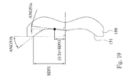
- FIG. 19 shows a schematic view of the parameters ANG 51 a and ANG 51 b of the fifth lens element of the image capturing lens assembly of FIG. 1 .
- An image capturing lens assembly includes, in order from an object side to an image side, a first lens element, a second lens element, a third lens element, a fourth lens element, a fifth lens element and a sixth lens element, wherein the image capturing lens assembly has a total of six lens element with refractive power.
- the image capturing lens assembly further includes a stop, such as an aperture stop, which is located between an object and the third lens element.
- each of the first through sixth lens elements of the image capturing lens assembly is a single and non-cemented lens element.
- the manufacturing process of the cemented lenses is more complex than the non-cemented lenses.
- an image-side surface of one lens and an object-side surface of the following lens need to have accurate curvature to ensure these two lens elements will be highly cemented.
- those two lens elements might not be highly cemented due to displacement and it is thereby not favorable for the image quality of the image capturing lens assembly. Therefore, each of the six lens elements of the image capturing lens assembly is separated from each other in the present disclosure for improving the problem generated by the cemented lens elements.
- the first lens element with positive refractive power has an object-side surface being convex in a paraxial region thereof. Therefore, the positive refractive power of the first lens element is adjusted for reducing the total track length of the image capturing lens assembly.
- the second lens element with negative refractive power can have an image-side surface being concave in a paraxial region thereof, so that the aberration generated from the first lens element with positive refractive power can be corrected.
- the third lens element can have positive refractive power, and can have an object-side surface being concave in a paraxial region thereof and an image-side surface being convex in a paraxial region thereof, that is, the third lens element is meniscus in the paraxial region thereof. Therefore, the excessive spherical aberration can be avoided, and the astigmatism can be reduced effectively.
- the fourth lens element can have an object-side surface being concave in a paraxial region thereof and an image-side surface being convex in a paraxial region thereof, that is, the fourth lens element is meniscus in the paraxial region thereof. Therefore, the astigmatism can be corrected effectively.
- the fifth lens element can have negative refractive power, and can have an object-side surface being convex in a paraxial region thereof and an image-side surface being concave in a paraxial region thereof, that is, the fifth lens element is meniscus in the paraxial region thereof. Therefore, the Petzval Sum of the image capturing lens assembly can be corrected for obtaining a sharper image. Furthermore, at least one of the object-side surface and the image-side surface of the fifth lens element has at least one inflection point thereon, so that the incident angle of the off-axis on the image plane can be reduced so as to increase the responding efficiency of an image sensor.
- the sixth lens element with positive refractive power can have an object-side surface being convex in a paraxial region thereof, and has an image-side surface being convex in a paraxial region thereof. Therefore the characteristic of the symmetry of the image capturing lens assembly can be obtained by the cooperation of the sixth lens element and the convex object-side surface of the first lens element with positive refractive power for controlling the various aberrations, and the compact size of the image capturing lens assembly can also be obtained.
- a focal length of the first lens element is f 1
- a focal length of the sixth lens element is f 6
- the following condition is satisfied: 0 ⁇ f 1 /f 6 ⁇ 0.9. Therefore, the various aberrations of the image capturing lens assembly can be controlled and the total track length thereof can be reduced by the combination of the sixth lens element with positive refractive power and the first lens element with positive refractive power.
- the following condition is satisfied: 0 ⁇ f 1 /f 6 ⁇ 0.5.
- a central thickness of the first lens element is CT 1
- a central thickness of the second lens element is CT 2
- a central thickness of the third lens element is CT 3
- a central thickness of the fourth lens element is CT 4
- a central thickness of the fifth lens element is CT 5
- a central thickness of the sixth lens element is CT 6
- an axial distance between the object-side surface of the first lens element and the image-side surface of the sixth lens element is TD, and the following condition is satisfied: 0.55 ⁇ (CT 1 +CT 2 +CT 3 +CT 4 +CT 5 +CT 6 )/TD ⁇ 0.90. Therefore, it is favorable for manufacturing the lens elements so as to obtain the compact size of the image capturing lens assembly.
- a stop can also be placed between the object and the first lens element, wherein when an axial distance between the stop and the image plane is SL, and an axial distance between the object-side surface of the first lens element and the image plane is TL, the following condition is satisfied: 0.80 ⁇ SL/TL ⁇ 1.20. Therefore, the total track length can be reduced so as to maintain the compact size of the image capturing lens assembly. Preferably, the following condition is satisfied: 0.93 ⁇ SL/TL ⁇ 1.10.
- the image capturing lens assembly further includes an image sensor located on the image plane.
- an image sensor located on the image plane.
- the lens elements can be made of plastic or glass material.
- the distribution of the refractive power of the image capturing lens assembly can be more flexible to design.
- the manufacturing cost thereof can be reduced.
- surfaces of each lens element can be arranged to be aspheric to have more controllable variables for correcting the aberration thereof, and to further decrease the required number of the lens elements.
- the total track length of the image capturing lens assembly can be effectively reduced.
- an aperture stop can be configured as a front stop or a middle stop.
- a front stop disposed between an imaged object and the first lens element can provide a longer distance between an exit pupil of the system and an image plane, which improves the image-sensing efficiency of the image sensor.
- a middle stop disposed between the first lens element and the image plane is favorable for enlarging the field of view of the system and thereby provides a wider field of view for the same.
- the image capturing lens assembly can include at least one stop, such as an aperture stop, a glare stop or a field stop. Said glare stop or said field stop is for correcting the unexpected light and thereby improving the image quality thereof.
- the image capturing lens assembly of the present disclosure when a lens element has a convex surface, it indicates that the surface is convex in a paraxial region thereof; and when a lens element has a concave surface, it indicates that the surface is concave in a paraxial region thereof.
- the paraxial region thereof refers to the region of the surface where light rays travel close to an optical axis and an off-axis region thereof refers to the region of the surface where light rays travel away from the optical axis.
- the image capturing lens assembly provides good correction ability and high image quality, and can be applied to 3D (three-dimensional) image capturing applications, in products such as digital cameras, tablets, and other mobile devices.
- an image capturing device including the image capturing lens assembly according to the aforementioned image capturing lens assembly of the present disclosure is provided. Therefore, a balanced characteristic of the image capturing device for controlling the various aberrations, and the compact size of the image capturing device can be obtained.
- FIG. 1 is a schematic view of an image capturing lens assembly according to the 1st embodiment of the present disclosure.
- FIG. 2 shows spherical aberration curves, astigmatic field curves and a distortion curve of the image capturing lens assembly according to the 1st embodiment.
- the image capturing lens assembly includes, in order from an object side to an image side, an aperture stop 100 , a first lens element 110 , a second lens element 120 , a third lens element 130 , a fourth lens element 140 , a fifth lens element 150 , a sixth lens element 160 , an IR-cut filter 180 , an image plane 170 and an image sensor 190 , wherein the image capturing lens assembly has a total of six lens elements with refractive power, and an air distance is between two adjacent surfaces of any two adjacent lens elements.
- the first lens element 110 with positive refractive power has an object-side surface 111 being convex in a paraxial region thereof and an image-side surface 112 being convex in a paraxial region thereof.
- the first lens element 110 is made of plastic material, and has the object-side surface 111 and the image-side surface 112 being both aspheric.
- the second lens element 120 with negative refractive power has an object-side surface 121 being convex in a paraxial region thereof and an image-side surface 122 being concave in a paraxial region thereof.
- the second lens element 120 is made of plastic material, and has the object-side surface 121 and the image-side surface 122 being both aspheric.
- the third lens element 130 with positive refractive power has an object-side surface 131 being concave in a paraxial region thereof and an image-side surface 132 being convex in a paraxial region thereof, that is, the third lens element 130 is meniscus in the paraxial region thereof.
- the third lens element 130 is made of plastic material, and has the object-side surface 131 and the image-side surface 132 being both aspheric.
- the fourth lens element 140 with positive refractive power has an object-side surface 141 being concave in a paraxial region thereof and an image-side surface 142 being convex in a paraxial region thereof, that is, the fourth lens element 140 is meniscus in the paraxial region thereof.
- the fourth lens element 140 is made of plastic material, and has the object-side surface 141 and the image-side surface 142 being both aspheric.
- the fifth lens element 150 with negative refractive power has an object-side surface 151 being convex in a paraxial region thereof and an image-side surface 152 being concave in a paraxial region thereof, that is, the fifth lens element 150 is meniscus in the paraxial region thereof.
- the fifth lens element 150 is made of plastic material and has the object-side surface 151 and the image-side surface 152 being both aspheric, wherein both of the object-side surface 151 and the image-side surface 152 of the fifth lens element 150 have inflection point thereon.
- the sixth lens element 160 with positive refractive power has an object-side surface 161 being convex in the paraxial region thereof and an image-side surface 162 being convex in the paraxial region thereof.
- the sixth lens element 160 is made of plastic material, and has the object-side surface 161 and the image-side surface 162 being both aspheric.
- the IR-cut filter 180 is made of glass material located between the sixth lens element 160 and the image plane 170 , and not affect the focal length of the image capturing lens assembly.
- X is the relative distance between a point on the aspheric surface spaced at a distance Y from the optical axis and the tangential plane at the aspheric surface vertex on the optical axis;
- Y is the distance from the point on the curve of the aspheric surface to the optical axis
- R is the curvature radius
- k is the conic coefficient
- Ai is the i-th aspheric coefficient.
- a central thickness of the first lens element 110 is CT 1
- a central thickness of the second lens element 120 is CT 2
- a central thickness of the third lens element 130 is CT 3
- a central thickness of the fourth lens element 140 is CT 4
- a central thickness of the fifth lens element 150 is CT 5
- a central thickness of the sixth lens element 160 is CT 6
- an axial distance between the object-side surface 111 of the first lens element 110 and the image-side surface 162 of the sixth lens element 160 is TD
- a curvature radius of the object-side surface 131 of the third lens element 130 is R 5
- a curvature radius of the image-side surface 132 of the third lens element 130 is R 6
- a curvature radius of the object-side surface 141 of the fourth lens element 140 is R 7
- a curvature radius of the image-side surface 142 of the fourth lens element 140 is R 8
- FIG. 19 shows a schematic view of the parameters ANG 51 a and ANG 51 b of the fifth lens element 150 of the image capturing lens assembly of FIG. 1 .
- an angle between a tangent line extended from a position on the object-side surface 151 of the fifth lens element 150 at a height of one third of the maximum effective semi-diameter and a normal line to an optical axis is ANG 51 a
- an angle between a tangent line extended from a maximum effective semi-diameter position on the object-side surface 151 of the fifth lens element 150 and a normal line to the optical axis is ANG 51 b
- an axial distance between the aperture stop 100 and the image plane 170 is SL
- an axial distance between the object-side surface 111 of the first lens element 110 and the image plane 170 is TL
- an axial distance between the image-side surface 162 of the sixth lens element 160 and the image plane 170 is BL
- Table 1 the curvature radius, the thickness and the focal length are shown in millimeters (mm).
- Surface numbers 0 - 16 represent the surfaces sequentially arranged from the object-side to the image-side along the optical axis.
- k represents the conic coefficient of the equation of the aspheric surface profiles.
- a 1 -A 14 represent the aspheric coefficients ranging from the 1st order to the 14th order.
- FIG. 3 is a schematic view of an image capturing lens assembly according to the 2nd embodiment of the present disclosure.
- FIG. 4 shows spherical aberration curves, astigmatic field curves and a distortion curve of the image capturing lens assembly according to the 2nd embodiment.
- the image capturing lens assembly includes, in order from an object side to an image side, an aperture stop 200 , a first lens element 210 , a second lens element 220 , a third lens element 230 , a fourth lens element 240 , a fifth lens element 250 , a sixth lens element 260 , an IR-cut filter 280 , an image plane 270 and an image sensor 290 , wherein the image capturing lens assembly has a total of six lens elements with refractive power, and an air distance is between two adjacent surfaces of any two adjacent lens elements.
- the first lens element 210 with positive refractive power has an object-side surface 211 being convex in a paraxial region thereof and an image-side surface 212 being convex in a paraxial region thereof.
- the first lens element 210 is made of plastic material, and has the object-side surface 211 and the image-side surface 212 being both aspheric.
- the second lens element 220 with negative refractive power has an object-side surface 221 being concave in a paraxial region thereof and an image-side surface 222 being concave in a paraxial region thereof.
- the second lens element 220 is made of plastic material, and has the object-side surface 221 and the image-side surface 222 being both aspheric.
- the third lens element 230 with positive refractive power has an object-side surface 231 being concave in a paraxial region thereof and an image-side surface 232 being convex in a paraxial region thereof, that is, the third lens element 230 is meniscus in the paraxial region thereof.
- the third lens element 230 is made of plastic material, and has the object-side surface 231 and the image-side surface 232 being both aspheric.
- the fourth lens element 240 with positive refractive power has an object-side surface 241 being concave in a paraxial region thereof and an image-side surface 242 being convex in a paraxial region thereof, that is, the fourth lens element 240 is meniscus in the paraxial region thereof.
- the fourth lens element 240 is made of plastic material, and has the object-side surface 241 and the image-side surface 242 being both aspheric.
- the fifth lens element 250 with negative refractive power has an object-side surface 251 being convex in a paraxial region thereof and an image-side surface 252 being concave in a paraxial region thereof, that is, the fifth lens element 250 is meniscus in the paraxial region thereof.
- the fifth lens element 250 is made of plastic material and has the object-side surface 251 and the image-side surface 252 being both aspheric, wherein both of the object-side surface 251 and the image-side surface 252 of the fifth lens element 250 have inflection point thereon.
- the sixth lens element 260 with positive refractive power has an object-side surface 261 being convex in the paraxial region thereof and an image-side surface 262 being convex in the paraxial region thereof.
- the sixth lens element 260 is made of plastic material, and has the object-side surface 261 and the image-side surface 262 being both aspheric.
- the IR-cut filter 280 is made of glass material located between the sixth lens element 260 and the image plane 270 , and will not affect the focal length of the image capturing lens assembly.
- FIG. 5 is a schematic view of an image capturing lens assembly according to the 3rd embodiment of the present disclosure.
- FIG. 6 shows spherical aberration curves, astigmatic field curves and a distortion curve of the image capturing lens assembly according to the 3rd embodiment.
- the image capturing lens assembly includes, in order from an object side to an image side, an aperture stop 300 , a first lens element 310 , a second lens element 320 , a third lens element 330 , a fourth lens element 340 , a fifth lens element 350 , a sixth lens element 360 , an IR-cut filter 380 , an image plane 370 and an image sensor 390 , wherein the image capturing lens assembly has a total of six lens elements with refractive power, and an air distance is between two adjacent surfaces of any two adjacent lens elements.
- the first lens element 310 with positive refractive power has an object-side surface 311 being convex in a paraxial region thereof and an image-side surface 312 being convex in a paraxial region thereof.
- the first lens element 310 is made of plastic material, and has the object-side surface 311 and the image-side surface 312 being both aspheric.
- the second lens element 320 with negative refractive power has an object-side surface 321 being convex in a paraxial region thereof and an image-side surface 322 being concave in a paraxial region thereof.
- the second lens element 320 is made of plastic material, and has the object-side surface 321 and the image-side surface 322 being both aspheric.
- the third lens element 330 with positive refractive power has an object-side surface 331 being concave in a paraxial region thereof and an image-side surface 332 being convex in a paraxial region thereof, that is, the third lens element 330 is meniscus in the paraxial region thereof.
- the third lens element 330 is made of plastic material, and has the object-side surface 331 and the image-side surface 332 being both aspheric.
- the fourth lens element 340 with positive refractive power has an object-side surface 341 being concave in a paraxial region thereof and an image-side surface 342 being convex in a paraxial region thereof, that is, the fourth lens element 340 is meniscus in the paraxial region thereof.
- the fourth lens element 340 is made of plastic material, and has the object-side surface 341 and the image-side surface 342 being both aspheric.
- the fifth lens element 350 with negative refractive power has an object-side surface 351 being convex in a paraxial region thereof and an image-side surface 352 being concave in a paraxial region thereof, that is, the fifth lens element 350 is meniscus in the paraxial region thereof.
- the fifth lens element 350 is made of plastic material and has the object-side surface 351 and the image-side surface 352 being both aspheric, wherein both of the object-side surface 351 and the image-side surface 352 of the fifth lens element 350 have inflection point thereon.
- the sixth lens element 360 with positive refractive power has an object-side surface 361 being convex in the paraxial region thereof and an image-side surface 362 being convex in the paraxial region thereof.
- the sixth lens element 360 is made of plastic material, and has the object-side surface 361 and the image-side surface 362 being both aspheric.
- the IR-cut filter 380 is made of glass material located between the sixth lens element 360 and the image plane 370 , and will not affect the focal length of the image capturing lens assembly.
- FIG. 7 is a schematic view of an image capturing lens assembly according to the 4th embodiment of the present disclosure.
- FIG. 8 shows spherical aberration curves, astigmatic field curves and a distortion curve of the image capturing lens assembly according to the 4th embodiment.
- the image capturing lens assembly includes, in order from an object side to an image side, an aperture stop 400 , a first lens element 410 , a second lens element 420 , a third lens element 430 , a fourth lens element 440 , a fifth lens element 450 , a sixth lens element 460 , an IR-cut filter 480 , an image plane 470 and an image sensor 490 , wherein the image capturing lens assembly has a total of six lens elements with refractive power, and an air distance is between two adjacent surfaces of any two adjacent lens elements.
- the first lens element 410 with positive refractive power has an object-side surface 411 being convex in a paraxial region thereof and an image-side surface 412 being convex in a paraxial region thereof.
- the first lens element 410 is made of plastic material, and has the object-side surface 411 and the image-side surface 412 being both aspheric.
- the second lens element 420 with negative refractive power has an object-side surface 421 being convex in a paraxial region thereof and an image-side surface 422 being concave in a paraxial region thereof.
- the second lens element 420 is made of plastic material, and has the object-side surface 421 and the image-side surface 422 being both aspheric.
- the third lens element 430 with positive refractive power has an object-side surface 431 being concave in a paraxial region thereof and an image-side surface 432 being convex in a paraxial region thereof, that is, the third lens element 430 is meniscus in the paraxial region thereof.
- the third lens element 430 is made of plastic material, and has the object-side surface 431 and the image-side surface 432 being both aspheric.
- the fourth lens element 440 with negative refractive power has an object-side surface 441 being concave in a paraxial region thereof and an image-side surface 442 being convex in a paraxial region thereof, that is, the fourth lens element 440 is meniscus in the paraxial region thereof.
- the fourth lens element 440 is made of plastic material, and has the object-side surface 441 and the image-side surface 442 being both aspheric.
- the fifth lens element 450 with negative refractive power has an object-side surface 451 being convex in a paraxial region thereof and an image-side surface 452 being concave in a paraxial region thereof, that is, the fifth lens element 450 is meniscus in the paraxial region thereof.
- the fifth lens element 450 is made of plastic material and has the object-side surface 451 and the image-side surface 452 being both aspheric, wherein both of the object-side surface 451 and the image-side surface 452 of the fifth lens element 450 have inflection point thereon.
- the sixth lens element 460 with positive refractive power has an object-side surface 461 being convex in the paraxial region thereof and an image-side surface 462 being convex in the paraxial region thereof.
- the sixth lens element 460 is made of plastic material, and has the object-side surface 461 and the image-side surface 462 being both aspheric.
- the IR-cut filter 480 is made of glass material located between the sixth lens element 460 and the image plane 470 , and will not affect the focal length of the image capturing lens assembly.
- FIG. 9 is a schematic view of an image capturing lens assembly according to the 5th embodiment of the present disclosure.
- FIG. 10 shows spherical aberration curves, astigmatic field curves and a distortion curve of the image capturing lens assembly according to the 5th embodiment.
- FIG. 10 shows spherical aberration curves, astigmatic field curves and a distortion curve of the image capturing lens assembly according to the 5th embodiment.
- the image capturing lens assembly includes, in order from an object side to an image side, a first lens element 510 , an aperture stop 500 , a second lens element 520 , a third lens element 530 , a fourth lens element 540 , a fifth lens element 550 , a sixth lens element 560 , an IR-cut filter 580 , an image plane 570 and an image sensor 590 , wherein the image capturing lens assembly has a total of six lens elements with refractive power, and an air distance is between two adjacent surfaces of any two adjacent lens elements.
- the first lens element 510 with positive refractive power has an object-side surface 511 being convex in a paraxial region thereof and an image-side surface 512 being convex in a paraxial region thereof.
- the first lens element 510 is made of plastic material, and has the object-side surface 511 and the image-side surface 512 being both aspheric.
- the second lens element 520 with negative refractive power has an object-side surface 521 being convex in a paraxial region thereof and an image-side surface 522 being concave in a paraxial region thereof.
- the second lens element 520 is made of plastic material, and has the object-side surface 521 and the image-side surface 522 being both aspheric.
- the third lens element 530 with positive refractive power has an object-side surface 531 being concave in a paraxial region thereof and an image-side surface 532 being convex in a paraxial region thereof, that is, the third lens element 530 is meniscus in the paraxial region thereof.
- the third lens element 530 is made of plastic material, and has the object-side surface 531 and the image-side surface 532 being both aspheric.
- the fourth lens element 540 with positive refractive power has an object-side surface 541 being concave in a paraxial region thereof and an image-side surface 542 being convex in a paraxial region thereof, that is, the fourth lens element 540 is meniscus in the paraxial region thereof.
- the fourth lens element 540 is made of plastic material, and has the object-side surface 541 and the image-side surface 542 being both aspheric.
- the fifth lens element 550 with negative refractive power has an object-side surface 551 being convex in a paraxial region thereof and an image-side surface 552 being concave in a paraxial region thereof, that is, the fifth lens element 550 is meniscus in the paraxial region thereof.
- the fifth lens element 550 is made of plastic material and has the object-side surface 551 and the image-side surface 552 being both aspheric, wherein both of the object-side surface 551 and the image-side surface 552 of the fifth lens element 550 have inflection point thereon.
- the sixth lens element 560 with positive refractive power has an object-side surface 561 being convex in the paraxial region thereof and an image-side surface 562 being convex in the paraxial region thereof.
- the sixth lens element 560 is made of plastic material, and has the object-side surface 561 and the image-side surface 562 being both aspheric.
- the IR-cut filter 580 is made of glass material located between the sixth lens element 560 and the image plane 570 , and will not affect the focal length of the image capturing lens assembly.
- FIG. 11 is a schematic view of an image capturing lens assembly according to the 6th embodiment of the present disclosure.
- FIG. 12 shows spherical aberration curves, astigmatic field curves and a distortion curve of the image capturing lens assembly according to the 6th embodiment.
- the image capturing lens assembly includes, in order from an object side to an image side, an aperture stop 600 , a first lens element 610 , a second lens element 620 , a third lens element 630 , a fourth lens element 640 , a fifth lens element 650 , a sixth lens element 660 , an IR-cut filter 680 , an image plane 670 and an image sensor 690 , wherein the image capturing lens assembly has a total of six lens elements with refractive power, and an air distance is between two adjacent surfaces of any two adjacent lens elements.
- the first lens element 610 with positive refractive power has an object-side surface 611 being convex in a paraxial region thereof and an image-side surface 612 being convex in a paraxial region thereof.
- the first lens element 610 is made of plastic material, and has the object-side surface 611 and the image-side surface 612 being both aspheric.
- the second lens element 620 with negative refractive power has an object-side surface 621 being concave in a paraxial region thereof and an image-side surface 622 being concave in a paraxial region thereof.
- the second lens element 620 is made of plastic material, and has the object-side surface 621 and the image-side surface 622 being both aspheric.
- the third lens element 630 with positive refractive power has an object-side surface 631 being concave in a paraxial region thereof and an image-side surface 632 being convex in a paraxial region thereof, that is, the third lens element 630 is meniscus in the paraxial region thereof.
- the third lens element 630 is made of plastic material, and has the object-side surface 631 and the image-side surface 632 being both aspheric.
- the fourth lens element 640 with negative refractive power has an object-side surface 641 being concave in a paraxial region thereof and an image-side surface 642 being convex in a paraxial region thereof, that is, the fourth lens element 640 is meniscus in the paraxial region thereof.
- the fourth lens element 640 is made of plastic material, and has the object-side surface 641 and the image-side surface 642 being both aspheric.
- the fifth lens element 650 with positive refractive power has an object-side surface 651 being convex in a paraxial region thereof and an image-side surface 652 being concave in a paraxial region thereof, that is, the fifth lens element 650 is meniscus in the paraxial region thereof.
- the fifth lens element 650 is made of plastic material and has the object-side surface 651 and the image-side surface 652 being both aspheric, wherein both of the object-side surface 651 and the image-side surface 652 of the fifth lens element 650 have inflection point thereon.
- the sixth lens element 660 with positive refractive power has an object-side surface 661 being convex in the paraxial region thereof and an image-side surface 662 being convex in the paraxial region thereof.
- the sixth lens element 660 is made of plastic material, and has the object-side surface 661 and the image-side surface 662 being both aspheric.
- the IR-cut filter 680 is made of glass material located between the sixth lens element 660 and the image plane 670 , and will not affect the focal length of the image capturing lens assembly.
- FIG. 13 is a schematic view of an image capturing lens assembly according to the 7th embodiment of the present disclosure.
- FIG. 14 shows spherical aberration curves, astigmatic field curves and a distortion curve of the image capturing lens assembly according to the 7th embodiment.
- the image capturing lens assembly includes, in order from an object side to an image side, an aperture stop 700 , a first lens element 710 , a second lens element 720 , a third lens element 730 , a fourth lens element 740 , a fifth lens element 750 , a sixth lens element 760 , an IR-cut filter 780 , an image plane 770 and an image sensor 790 , wherein the image capturing lens assembly has a total of six lens elements with refractive power, and an air distance is between two adjacent surfaces of any two adjacent lens elements.
- the first lens element 710 with positive refractive power has an object-side surface 711 being convex in a paraxial region thereof and an image-side surface 712 being convex in a paraxial region thereof.
- the first lens element 710 is made of plastic material, and has the object-side surface 711 and the image-side surface 712 being both aspheric.
- the second lens element 720 with negative refractive power has an object-side surface 721 being concave in a paraxial region thereof and an image-side surface 722 being concave in a paraxial region thereof.
- the second lens element 720 is made of plastic material, and has the object-side surface 721 and the image-side surface 722 being both aspheric.
- the third lens element 730 with positive refractive power has an object-side surface 731 being concave in a paraxial region thereof and an image-side surface 732 being convex in a paraxial region thereof, that is, the third lens element 730 is meniscus in the paraxial region thereof.
- the third lens element 730 is made of plastic material, and has the object-side surface 731 and the image-side surface 732 being both aspheric.
- the fourth lens element 740 with negative refractive power has an object-side surface 741 being concave in a paraxial region thereof and an image-side surface 742 being convex in a paraxial region thereof, that is, the fourth lens element 740 is meniscus in the paraxial region thereof.
- the fourth lens element 740 is made of plastic material, and has the object-side surface 741 and the image-side surface 742 being both aspheric.
- the fifth lens element 750 with positive refractive power has an object-side surface 751 being convex in a paraxial region thereof and an image-side surface 752 being concave in a paraxial region thereof, that is, the fifth lens element 750 is meniscus in the paraxial region thereof.
- the fifth lens element 750 is made of plastic material and has the object-side surface 751 and the image-side surface 752 being both aspheric, wherein both of the object-side surface 751 and the image-side surface 752 of the fifth lens element 750 have inflection point thereon.
- the sixth lens element 760 with positive refractive power has an object-side surface 761 being concave in the paraxial region thereof and an image-side surface 762 being convex in the paraxial region thereof.
- the sixth lens element 760 is made of plastic material, and has the object-side surface 761 and the image-side surface 762 being both aspheric.
- the IR-cut filter 780 is made of glass material located between the sixth lens element 760 and the image plane 770 , and will not affect the focal length of the image capturing lens assembly.
- FIG. 15 is a schematic view of an image capturing lens assembly according to the 8th embodiment of the present disclosure.
- FIG. 16 shows spherical aberration curves, astigmatic field curves and a distortion curve of the image capturing lens assembly according to the 8th embodiment.
- the image capturing lens assembly includes, in order from an object side to an image side, a first lens element 810 , an aperture stop 800 , a second lens element 820 , a third lens element 830 , a fourth lens element 840 , a fifth lens element 850 , a sixth lens element 860 , an IR-cut filter 880 , an image plane 870 and an image sensor 890 , wherein the image capturing lens assembly has a total of six lens elements with refractive power, and an air distance is between two adjacent surfaces of any two adjacent lens elements.
- the first lens element 810 with positive refractive power has an object-side surface 811 being convex in a paraxial region thereof and an image-side surface 812 being concave in a paraxial region thereof.
- the first lens element 810 is made of plastic material, and has the object-side surface 811 and the image-side surface 812 being both aspheric.
- the second lens element 820 with negative refractive power has an object-side surface 821 being convex in a paraxial region thereof and an image-side surface 822 being concave in a paraxial region thereof.
- the second lens element 820 is made of plastic material, and has the object-side surface 821 and the image-side surface 822 being both aspheric.
- the third lens element 830 with positive refractive power has an object-side surface 831 being concave in a paraxial region thereof and an image-side surface 832 being convex in a paraxial region thereof, that is, the third lens element 830 is meniscus in the paraxial region thereof.
- the third lens element 830 is made of plastic material, and has the object-side surface 831 and the image-side surface 832 being both aspheric.
- the fourth lens element 840 with positive refractive power has an object-side surface 841 being concave in a paraxial region thereof and an image-side surface 842 being convex in a paraxial region thereof, that is, the fourth lens element 840 is meniscus in the paraxial region thereof.
- the fourth lens element 840 is made of plastic material, and has the object-side surface 841 and the image-side surface 842 being both aspheric.
- the fifth lens element 850 with negative refractive power has an object-side surface 851 being convex in a paraxial region thereof and an image-side surface 852 being concave in a paraxial region thereof, that is, the fifth lens element 850 is meniscus in the paraxial region thereof.
- the fifth lens element 850 is made of plastic material and has the object-side surface 851 and the image-side surface 852 being both aspheric, wherein both of the object-side surface 851 and the image-side surface 852 of the fifth lens element 850 have inflection point thereon.
- the sixth lens element 860 with positive refractive power has an object-side surface 861 being concave in the paraxial region thereof and an image-side surface 862 being convex in the paraxial region thereof.
- the sixth lens element 860 is made of plastic material, and has the object-side surface 861 and the image-side surface 862 being both aspheric.
- the IR-cut filter 880 is made of glass material located between the sixth lens element 860 and the image plane 870 , and will not affect the focal length of the image capturing lens assembly.
- FIG. 17 is a schematic view of an image capturing lens assembly according to the 9th embodiment of the present disclosure.
- FIG. 18 shows spherical aberration curves, astigmatic field curves and a distortion curve of the image capturing lens assembly according to the 9th embodiment.
- FIG. 18 shows spherical aberration curves, astigmatic field curves and a distortion curve of the image capturing lens assembly according to the 9th embodiment.
- the image capturing lens assembly includes, in order from an object side to an image side, an aperture stop 900 , a first lens element 910 , a second lens element 920 , a third lens element 930 , a fourth lens element 940 , a fifth lens element 950 , a sixth lens element 960 , an IR-cut filter 980 , an image plane 970 and an image sensor 990 , wherein the image capturing lens assembly has a total of six lens elements with refractive power, and an air distance is between two adjacent surfaces of any two adjacent lens elements.
- the first lens element 910 with positive refractive power has an object-side surface 911 being convex in a paraxial region thereof and an image-side surface 912 being convex in a paraxial region thereof.
- the first lens element 910 is made of glass material, and has the object-side surface 911 and the image-side surface 912 being both aspheric.
- the second lens element 920 with negative refractive power has an object-side surface 921 being convex in a paraxial region thereof and an image-side surface 922 being concave in a paraxial region thereof.
- the second lens element 920 is made of plastic material, and has the object-side surface 921 and the image-side surface 922 being both aspheric.
- the third lens element 930 with positive refractive power has an object-side surface 931 being concave in a paraxial region thereof and an image-side surface 932 being convex in a paraxial region thereof, that is, the third lens element 930 is meniscus in the paraxial region thereof.
- the third lens element 930 is made of plastic material, and has the object-side surface 931 and the image-side surface 932 being both aspheric.
- the fourth lens element 940 with positive refractive power has an object-side surface 941 being concave in a paraxial region thereof and an image-side surface 942 being convex in a paraxial region thereof, that is, the fourth lens element 940 is meniscus in the paraxial region thereof.
- the fourth lens element 940 is made of plastic material, and has the object-side surface 941 and the image-side surface 942 being both aspheric.
- the fifth lens element 950 with negative refractive power has an object-side surface 951 being convex in a paraxial region thereof and an image-side surface 952 being concave in a paraxial region thereof, that is, the fifth lens element 950 is meniscus in the paraxial region thereof.
- the fifth lens element 950 is made of plastic material and has the object-side surface 951 and the image-side surface 952 being both aspheric, wherein both of the object-side surface 951 and the image-side surface 952 of the fifth lens element 950 have inflection point thereon.
- the sixth lens element 960 with positive refractive power has an object-side surface 961 being convex in the paraxial region thereof and an image-side surface 962 being convex in the paraxial region thereof.
- the sixth lens element 960 is made of plastic material, and has the object-side surface 961 and the image-side surface 962 being both aspheric.
- the IR-cut filter 980 is made of glass material located between the sixth lens element 960 and the image plane 970 , and will not affect the focal length of the image capturing lens assembly.
Landscapes
- Physics & Mathematics (AREA)
- General Physics & Mathematics (AREA)
- Optics & Photonics (AREA)
- Lenses (AREA)
Applications Claiming Priority (3)
| Application Number | Priority Date | Filing Date | Title |
|---|---|---|---|
| TW102128672A TWI465762B (zh) | 2013-08-09 | 2013-08-09 | 影像擷取系統透鏡組及取像裝置 |
| TW102128672 | 2013-08-09 | ||
| TW102128672A | 2013-08-09 |
Publications (2)
| Publication Number | Publication Date |
|---|---|
| US20150042862A1 US20150042862A1 (en) | 2015-02-12 |
| US9128264B2 true US9128264B2 (en) | 2015-09-08 |
Family
ID=50157353
Family Applications (1)
| Application Number | Title | Priority Date | Filing Date |
|---|---|---|---|
| US14/018,444 Active 2034-01-10 US9128264B2 (en) | 2013-08-09 | 2013-09-05 | Image capturing lens assembly and image capturing device |
Country Status (3)
| Country | Link |
|---|---|
| US (1) | US9128264B2 (zh) |
| CN (2) | CN106249386B (zh) |
| TW (1) | TWI465762B (zh) |
Cited By (3)
| Publication number | Priority date | Publication date | Assignee | Title |
|---|---|---|---|---|
| US10921565B2 (en) | 2014-07-30 | 2021-02-16 | Largan Precision Co., Ltd. | Imaging optical system, image capturing device, and electronic device |
| US11243382B2 (en) | 2015-04-15 | 2022-02-08 | Largan Precision Co., Ltd. | Photographing lens assembly, image capturing unit and electronic device |
| US11347028B2 (en) | 2017-11-20 | 2022-05-31 | Samsung Electro-Mechanics Co., Ltd. | Optical imaging system |
Families Citing this family (29)
| Publication number | Priority date | Publication date | Assignee | Title |
|---|---|---|---|---|
| CN103969805B (zh) * | 2013-12-10 | 2016-08-17 | 玉晶光电(厦门)有限公司 | 光学成像镜头及应用此镜头之电子装置 |
| JP6226376B2 (ja) | 2013-12-25 | 2017-11-08 | カンタツ株式会社 | 撮像レンズ |
| TWI503570B (zh) * | 2014-05-26 | 2015-10-11 | Ability Opto Electronics Technologyco Ltd | 微小型光學影像擷取模組 |
| CN105204137B (zh) * | 2014-05-26 | 2017-08-04 | 先进光电科技股份有限公司 | 微小型光学影像撷取模块 |
| US10133030B2 (en) | 2014-06-17 | 2018-11-20 | Samsung Electro-Mechanics Co., Ltd. | High resolution lens module |
| KR102126419B1 (ko) | 2014-10-20 | 2020-06-24 | 삼성전기주식회사 | 촬상 광학계 |
| KR101709834B1 (ko) * | 2014-10-30 | 2017-02-23 | 삼성전기주식회사 | 렌즈 모듈 |
| JP2016114633A (ja) * | 2014-12-11 | 2016-06-23 | ソニー株式会社 | 撮像レンズおよび撮像装置 |
| CN104820276B (zh) * | 2015-01-23 | 2017-04-12 | 玉晶光电(厦门)有限公司 | 可携式电子装置与其光学成像镜头 |
| JP6554824B2 (ja) * | 2015-03-03 | 2019-08-07 | 株式会社リコー | 焦点深度拡張結像光学系および撮像装置 |
| TWI548895B (zh) | 2015-07-03 | 2016-09-11 | 大立光電股份有限公司 | 取像鏡片系統、取像裝置及電子裝置 |
| KR101762004B1 (ko) | 2015-07-16 | 2017-07-26 | 삼성전기주식회사 | 촬상 광학계 |
| CN109709664B (zh) * | 2015-07-24 | 2021-05-18 | 大立光电股份有限公司 | 光学摄像镜组及取像装置 |
| KR101912276B1 (ko) * | 2015-08-10 | 2019-01-14 | 삼성전기 주식회사 | 촬상 광학계 |
| TWI585455B (zh) | 2015-10-20 | 2017-06-01 | 大立光電股份有限公司 | 影像擷取透鏡系統、取像裝置及電子裝置 |
| US10185123B2 (en) * | 2015-10-22 | 2019-01-22 | Apple Inc. | Lens system |
| KR101681455B1 (ko) | 2016-07-28 | 2016-11-30 | 삼성전기주식회사 | 렌즈 모듈 |
| KR101973429B1 (ko) | 2016-08-09 | 2019-04-29 | 삼성전기주식회사 | 촬상 광학계 |
| JP6482509B2 (ja) | 2016-08-29 | 2019-03-13 | カンタツ株式会社 | 撮像レンズ |
| KR102409698B1 (ko) * | 2016-09-12 | 2022-06-16 | 삼성전기주식회사 | 촬상 광학계 |
| JP2018092081A (ja) * | 2016-12-07 | 2018-06-14 | 富士フイルム株式会社 | 結像レンズおよび光学装置 |
| CN106990511B (zh) * | 2017-06-05 | 2022-08-09 | 浙江舜宇光学有限公司 | 成像镜头 |
| TWI641865B (zh) | 2017-09-27 | 2018-11-21 | 大立光電股份有限公司 | 光學成像鏡組、取像裝置及電子裝置 |
| KR20180078217A (ko) * | 2018-07-02 | 2018-07-09 | 삼성전기주식회사 | 촬상 광학계 |
| KR101973454B1 (ko) | 2019-01-04 | 2019-04-29 | 삼성전기주식회사 | 촬상 광학계 |
| US11480760B2 (en) * | 2019-04-18 | 2022-10-25 | Sintai Optical (Shenzhen) Co., Ltd. | Lens assembly |
| CN110398824B (zh) * | 2019-06-30 | 2021-08-17 | 瑞声光学解决方案私人有限公司 | 摄像光学镜头 |
| CN110231702B (zh) * | 2019-08-01 | 2019-11-08 | 江西联益光学有限公司 | 光学镜头及成像设备 |
| KR102494344B1 (ko) * | 2021-04-26 | 2023-02-06 | 삼성전기주식회사 | 촬상 광학계 |
Citations (6)
| Publication number | Priority date | Publication date | Assignee | Title |
|---|---|---|---|---|
| JPH03296705A (ja) | 1990-04-17 | 1991-12-27 | Ricoh Co Ltd | スキャナー用読取レンズ |
| US5313330A (en) | 1992-08-31 | 1994-05-17 | U.S. Precision Lens Incorporated | Zoom projection lens systems |
| JP2002341242A (ja) | 2001-05-21 | 2002-11-27 | Matsushita Electric Ind Co Ltd | 投写レンズとそれを用いたプロジェクター |
| US20120243108A1 (en) * | 2011-03-25 | 2012-09-27 | Largan Precision Co., Ltd. | Photographing optical lens assembly |
| US20120314301A1 (en) * | 2011-06-10 | 2012-12-13 | Largan Precision Co., Ltd. | Optical image capturing lens assembly |
| US20130010181A1 (en) | 2010-03-24 | 2013-01-10 | Sony Corporation | Optical unit and imaging apparatus |
Family Cites Families (6)
| Publication number | Priority date | Publication date | Assignee | Title |
|---|---|---|---|---|
| JP5042767B2 (ja) * | 2007-10-05 | 2012-10-03 | 富士フイルム株式会社 | 撮像レンズおよび撮像装置 |
| TWI439720B (zh) * | 2011-03-11 | 2014-06-01 | Largan Precision Co Ltd | 影像擷取鏡片組 |
| CN104246571A (zh) * | 2012-01-30 | 2014-12-24 | 富士胶片株式会社 | 摄像镜头以及具备摄像镜头的摄像装置 |
| TWI448721B (zh) * | 2012-06-19 | 2014-08-11 | Largan Precision Co Ltd | 影像透鏡系統組 |
| JP5975386B2 (ja) * | 2012-08-17 | 2016-08-23 | 株式会社オプトロジック | 撮像レンズ |
| TWI479191B (zh) * | 2013-01-04 | 2015-04-01 | Largan Precision Co Ltd | 光學結像系統 |
-
2013
- 2013-08-09 TW TW102128672A patent/TWI465762B/zh active
- 2013-09-05 US US14/018,444 patent/US9128264B2/en active Active
- 2013-10-09 CN CN201610806486.7A patent/CN106249386B/zh active Active
- 2013-10-09 CN CN201310467091.5A patent/CN104345433B/zh active Active
Patent Citations (6)
| Publication number | Priority date | Publication date | Assignee | Title |
|---|---|---|---|---|
| JPH03296705A (ja) | 1990-04-17 | 1991-12-27 | Ricoh Co Ltd | スキャナー用読取レンズ |
| US5313330A (en) | 1992-08-31 | 1994-05-17 | U.S. Precision Lens Incorporated | Zoom projection lens systems |
| JP2002341242A (ja) | 2001-05-21 | 2002-11-27 | Matsushita Electric Ind Co Ltd | 投写レンズとそれを用いたプロジェクター |
| US20130010181A1 (en) | 2010-03-24 | 2013-01-10 | Sony Corporation | Optical unit and imaging apparatus |
| US20120243108A1 (en) * | 2011-03-25 | 2012-09-27 | Largan Precision Co., Ltd. | Photographing optical lens assembly |
| US20120314301A1 (en) * | 2011-06-10 | 2012-12-13 | Largan Precision Co., Ltd. | Optical image capturing lens assembly |
Cited By (6)
| Publication number | Priority date | Publication date | Assignee | Title |
|---|---|---|---|---|
| US10921565B2 (en) | 2014-07-30 | 2021-02-16 | Largan Precision Co., Ltd. | Imaging optical system, image capturing device, and electronic device |
| US11243382B2 (en) | 2015-04-15 | 2022-02-08 | Largan Precision Co., Ltd. | Photographing lens assembly, image capturing unit and electronic device |
| US11754816B2 (en) | 2015-04-15 | 2023-09-12 | Largan Precision Co., Ltd. | Photographing lens assembly, image capturing unit and electronic device |
| US12078786B2 (en) | 2015-04-15 | 2024-09-03 | Largan Precision Co., Ltd. | Photographing lens assembly, image capturing unit and electronic device |
| US11347028B2 (en) | 2017-11-20 | 2022-05-31 | Samsung Electro-Mechanics Co., Ltd. | Optical imaging system |
| US12092899B2 (en) | 2017-11-20 | 2024-09-17 | Samsung Electro-Mechanics Co., Ltd. | Optical imaging system |
Also Published As
| Publication number | Publication date |
|---|---|
| CN106249386B (zh) | 2018-10-26 |
| TWI465762B (zh) | 2014-12-21 |
| CN104345433B (zh) | 2016-11-02 |
| US20150042862A1 (en) | 2015-02-12 |
| CN106249386A (zh) | 2016-12-21 |
| TW201348735A (zh) | 2013-12-01 |
| CN104345433A (zh) | 2015-02-11 |
Similar Documents
| Publication | Publication Date | Title |
|---|---|---|
| US11391927B2 (en) | Optical lens assembly, image capturing apparatus and electronic device | |
| US9128264B2 (en) | Image capturing lens assembly and image capturing device | |
| US9857562B2 (en) | Photographing optical lens assembly, image capturing device and mobile terminal | |
| US9791672B2 (en) | Optical image capturing system | |
| US9104014B2 (en) | Imaging lens system and image capturing device | |
| US9557530B2 (en) | Photographing optical lens assembly, image capturing unit and mobile device | |
| US9146381B2 (en) | Optical image capturing lens assembly | |
| US9323028B2 (en) | Optical image capturing system | |
| US9239447B1 (en) | Optical imaging lens assembly, image capturing unit and electronic device | |
| US9201216B2 (en) | Image capturing lens assembly, image capturing device and mobile terminal | |
| US9063271B2 (en) | Optical imaging lens assembly and image capturing device | |
| US8896936B2 (en) | Image capturing lens assembly | |
| US9316811B2 (en) | Photographing lens assembly, image capturing device and mobile terminal | |
| US9335522B2 (en) | Photographing optical lens assembly, image capturing unit and electronic device | |
| US9097877B2 (en) | Image lens assembly and image capturing device | |
| US8913329B1 (en) | Image lens assembly | |
| US9140878B2 (en) | Photographing lens assembly and image capturing device | |
| US9348115B1 (en) | Photographing lens system, image capturing device and electronic terminal | |
| US20150227021A1 (en) | Optical photographing lens assembly, imaging unit and electronic device | |
| US9104012B2 (en) | Image lens assembly, image capturing device and mobile terminal | |
| US8953257B1 (en) | Image capturing lens system and image capturing device | |
| US9557535B1 (en) | Photographing optical system, image capturing device and electronic device |
Legal Events
| Date | Code | Title | Description |
|---|---|---|---|
| AS | Assignment |
Owner name: LARGAN PRECISION CO., LTD., TAIWAN Free format text: ASSIGNMENT OF ASSIGNORS INTEREST;ASSIGNOR:HUANG, HSIN-HSUAN;REEL/FRAME:031160/0283 Effective date: 20130822 |
|
| STCF | Information on status: patent grant |
Free format text: PATENTED CASE |
|
| MAFP | Maintenance fee payment |
Free format text: PAYMENT OF MAINTENANCE FEE, 4TH YEAR, LARGE ENTITY (ORIGINAL EVENT CODE: M1551); ENTITY STATUS OF PATENT OWNER: LARGE ENTITY Year of fee payment: 4 |
|
| MAFP | Maintenance fee payment |
Free format text: PAYMENT OF MAINTENANCE FEE, 8TH YEAR, LARGE ENTITY (ORIGINAL EVENT CODE: M1552); ENTITY STATUS OF PATENT OWNER: LARGE ENTITY Year of fee payment: 8 |