US9046694B2 - Cooling apparatus for endoscope and endoscope system - Google Patents
Cooling apparatus for endoscope and endoscope system Download PDFInfo
- Publication number
- US9046694B2 US9046694B2 US12/048,292 US4829208A US9046694B2 US 9046694 B2 US9046694 B2 US 9046694B2 US 4829208 A US4829208 A US 4829208A US 9046694 B2 US9046694 B2 US 9046694B2
- Authority
- US
- United States
- Prior art keywords
- distal end
- sheath
- insertion portion
- endoscope
- main body
- Prior art date
- Legal status (The legal status is an assumption and is not a legal conclusion. Google has not performed a legal analysis and makes no representation as to the accuracy of the status listed.)
- Active, expires
Links
Images


Classifications
-
- G—PHYSICS
- G02—OPTICS
- G02B—OPTICAL ELEMENTS, SYSTEMS OR APPARATUS
- G02B23/00—Telescopes, e.g. binoculars; Periscopes; Instruments for viewing the inside of hollow bodies; Viewfinders; Optical aiming or sighting devices
- G02B23/24—Instruments or systems for viewing the inside of hollow bodies, e.g. fibrescopes
- G02B23/2476—Non-optical details, e.g. housings, mountings, supports
- G02B23/2492—Arrangements for use in a hostile environment, e.g. a very hot, cold or radioactive environment
Definitions
- the present invention relates to an endoscope cooling device to be attached at an insertion portion of an endoscope for observing a test substance and to an endoscope system including the endoscope cooling device and the endoscope.
- an endoscope having an insertion portion, which can be inserted into a test substance in order to make observable a narrowed part such as a duct for which an observer is, otherwise, unable to make a direct visual observation
- An observation portion such as a solid-state image sensor (for example, a CCD) is disposed at the distal end of an insertion portion of the endoscope, thus making it possible to observe a test substance in the vicinity of the distal end of the insertion portion.
- an illuminating means is installed at the distal end of the insertion portion, thus making it possible to illuminate the vicinity of the distal end of the insertion portion and preferably observe the test substance.
- the insertion portion of the endoscope is provided as described above at the distal end with an observation portion such as a solid-state image sensor (for example, a CCD) and an illuminating means, it is restricted to a maximum allowable working temperature of up to about 80° C., in relation to heat-resistant temperatures of these devices taken into account.
- an industrial endoscope has been proposed, which allows an operator to make an observation under the above high-temperature environment (for example, refer to Japanese Unexamined Patent Application, First Publication No. 2000-46482).
- the industrial endoscope disclosed in the document Japanese Unexamined Patent Application, First Publication No. 2000-46482
- an inner flexible body an insertion portion having an outer flexible body installed by forming a space for flowing a fluid between itself and the inner flexible body, an outer casing fixed to the proximal end of the outer flexible body, the interior of which is communicatively connected to a space in which the fluid flows, and a valve fixed to the outer casing and allowing the fluid to flow into the outer casing.
- the valve is connected to a fluid supply device for supplying a cooling fluid by using a supply duct, thus allowing the cooling fluid to flow, by which the cooling fluid is released from the distal end from the interior of the outer casing through a space between the inner flexible body and the outer flexible body.
- the endoscope can be used at high temperatures due to cooling by the cooling fluid.
- a first aspect of the endoscope cooling device of the present invention is an endoscope cooling device for cooling an insertion portion having an observation portion at the distal end.
- the endoscope cooling device is provided with an inner sheath into which the distal end portion of the insertion portion including the observation portion is inserted to form a first flow path of a cooling fluid between the outer circumferential face of the insertion portion and the inner circumferential face of the inner sheath, an outer sheath into which the inner sheath is inserted to form a second flow path of the cooling fluid between the outer circumferential face of the inner sheath and the inner circumferential face of the outer sheath, and a regulating means for regulating the distal end portion in moving at least either through the inner sheath or the outer sheath, and a fluid supply means for supplying the cooling fluid to the first flow path and the second flow path.
- the regulating means may regulate the distal end portion in moving rotationally around the central axis at least either through the inner sheath or the outer sheath or may regulate the distal end portion in moving back and forth in the direction of the central axis at least either through the inner sheath or the outer sheath.
- the regulating means may be provided with a raised portion installed at one end of the inner sheath and the outer sheath or the distal end portion and a recessed portion installed at the other end of the inner sheath and the outer sheath or the distal end portion and engaged with the raised portion.
- the regulating means may be provided with an auxiliary member fitted to the outside of the distal end portion.
- the raised portion or the recessed portion is preferably formed on the auxiliary member.
- the first aspect of the endoscope cooling device of the present invention may be provided with a cap attached to the distal end of the outer sheath to close the distal end.
- the regulating means is preferably provided with a fixing portion fixed to the distal end portion and an engagement portion projecting outwardly from the fixing portion and held between the distal end of the outer sheath and the cap.
- the regulating means may be provided with a first annular member elastically deformed and fitted between the outer circumferential face of the distal end portion and the inner circumferential face of the inner sheath and a second annular member elastically deformed and fitted between the outer circumferential face of the inner sheath and the outer sheath.
- an opening portion penetrating through the inner sheath in a radial direction may be formed at the distal end of the inner sheath.
- the first aspect of the endoscope cooling device of the present invention may be provided with an arrangement means for arranging the distal end portion at the center of the inner sheath.
- the regulating means may also act as the arrangement means.
- the first aspect of the endoscope cooling device of the present invention may be provided with a cap attached at the distal end of the outer sheath to close the distal end.
- the cooling fluid preferably flows through the first flow path toward the distal end of the insertion portion and turns back in the vicinity of the distal end of the inner sheath to flow through the second flow path toward the proximal end of the outer sheath.
- the cooling fluid may be supplied in a circulating manner to the first flow path and the second flow path.
- the first aspect of the endoscope cooling device of the present invention may be provided with a first sealing member arranged between the outer circumferential face at the proximal end of the insertion portion and the inner circumferential face of the inner sheath to seal the first flow path and a second sealing member arranged between the outer circumferential face at the proximal end of the inner sheath and the inner circumferential face of the outer sheath to seal the second flow path.
- At least one of the first sealing member and the second sealing member may be an elastically deformable rubber member.
- the cooling fluid may be discharged backward from the proximal end of the outer sheath.
- a second aspect of the endoscope cooling device of the present invention is a endoscope cooling device for cooling an insertion portion having an observation portion at the distal end, which is provided with a sheath into which the distal end portion of the insertion portion including the observation portion is inserted to form a flow path of a cooling fluid between the outer circumferential face of the insertion portion and the inner circumferential face of the sheath, a regulating means for regulating the distal end portion in moving through the sheath, and a fluid supply means for supplying the cooling fluid to the flow path.
- the regulating means may regulate the distal end portion in moving rotationally around the central axis through the sheath or may regulate the distal end portion in moving back and forth through the sheath in the direction of the central axis.
- the regulating means may be provided with a raised portion installed at one end of either the sheath or the distal end portion and a recessed portion installed at the other end of either the sheath or the distal end portion and engaged with the raised portion.
- the regulating means may be provided with an auxiliary member fitted to the outside of the distal end portion.
- the raised portion or the recessed portion is preferably formed on the auxiliary member.
- the second aspect of the endoscope cooling device of the present invention may be provided with an urging means for pressing the raised portion against the recessed portion.
- the urging means may be a spring member or the cooling fluid flowing through the flow path toward the distal end of the insertion portion.
- the second aspect of the endoscope cooling device of the present invention may be provided with an arrangement means for arranging the distal end portion at the center of the sheath.
- the arrangement means may be a raised portion projecting from one end of either the outer circumferential face of the distal end portion or the inner circumferential face of the sheath and in contact with the other end of either the outer circumferential face of the distal end portion or the inner circumferential face of the sheath.
- the regulating means may also act as the arrangement means.
- the cooling fluid may flow through the flow path toward the distal end of the insertion portion and be discharged forward from the distal end of the sheath.
- the second aspect of the endoscope cooling device of the present invention may be provided with a cap having an opening portion and attached at the distal end of the sheath.
- the cooling fluid flows through the flow path toward the distal end of the insertion portion and is discharged in front of the sheath through the opening portion of the cap.
- the second aspect of the endoscope cooling device of the present invention may be provided with a cap attached at the distal end of the sheath to close the distal end.
- a cap attached at the distal end of the sheath to close the distal end.
- an opening portion penetrating through the sheath in a radial direction is formed at the distal end of the sheath.
- the cooling fluid may flow through the flow path toward the distal end of the insertion portion and be discharged around the sheath through the opening portion of the sheath.
- the second aspect of the endoscope cooling device of the present invention may be provided with a porous member arranged between the outer circumferential face at the distal end of the insertion portion and the inner circumferential face of the sheath.
- water used as the cooling fluid may flow through the flow path toward the distal end of the insertion portion and be supplied to the porous member.
- the sheath may be partially composed of a porous member.
- the cooling fluid flows through the flow path toward the distal end of the insertion portion and is discharged around the sheath through the porous member.
- the sheath may be closed at the distal end.
- the cooling fluid flows through a working channel of the insertion portion and is discharged from an outlet of the working channel installed at the distal end portion, flowing through the flow path toward the proximal end of the insertion portion.
- the second aspect of the endoscope cooling device of the present invention may be provided with a sealing member arranged between the outer circumferential face at the proximal end of the insertion portion and the inner circumferential face of the sheath to seal the flow path.
- the sealing member may be an elastically deformable rubber member.
- the endoscope system of the present invention is provided with any one of the above-described endoscope cooling devices and an endoscope having the insertion portion.
- FIG. 1 is an overall block diagram showing a first embodiment of the endoscope system of the present invention.
- FIG. 2 is a sectional side view of the sheath of the endoscope cooling device included in the first embodiment.
- FIG. 3 is an exploded perspective view of the distal end portion of the sheath constituting the endoscope cooling device included in the first embodiment.
- FIG. 4 is a sectional view taken along the cutting-plane line A to A in FIG. 2 .
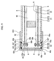
- FIG. 5 is a view showing a second embodiment of the endoscope system of the present invention and an exploded perspective view of the distal end portion of the sheath constituting the endoscope cooling device included in the present embodiment.
- FIG. 6 is a side sectional view of the sheath of the endoscope cooling device included in the second embodiment.
- FIG. 7 is a view showing an exemplified variation of the second embodiment and a sectional side view of the distal end portion constituting the sheath of the endoscope cooling device included in the exemplified variation.
- FIG. 8 is a view showing a third embodiment of the endoscope system of the present invention and an exploded perspective view of the distal end portion of the sheath constituting the endoscope cooling device included in the present embodiment.
- FIG. 9 is a sectional side view of the sheath of the endoscope cooling device included in the third embodiment.
- FIG. 10 is a view showing a fourth embodiment of the endoscope system of the present invention and an exploded perspective view of the distal end portion of the sheath constituting the endoscope cooling device included in the present embodiment.
- FIG. 11 is a sectional side view of the sheath of the endoscope cooling device included in the fourth embodiment.
- FIG. 12 is a view showing an exemplified variation of the fourth embodiment and an exploded perspective view of the distal end portion of the sheath constituting the endoscope cooling device included in the exemplified variation.
- FIG. 13 is a view showing a fifth embodiment of the endoscope system of the present invention and an exploded perspective view of the distal end portion of the sheath constituting the endoscope cooling device included in the present embodiment.
- FIG. 14 is a view showing a sixth embodiment of the endoscope system of the present invention and an exploded perspective view of the distal end portion of the sheath constituting the endoscope cooling device included in the present embodiment.
- FIG. 15 is a sectional side view of the sheath of the endoscope cooling device included in the sixth embodiment.
- FIG. 16 is a view showing a seventh embodiment of the endoscope system of the present invention and an exploded perspective view of the distal end portion of the sheath constituting the endoscope cooling device included in the present embodiment.
- FIG. 17 is a sectional side view of the sheath of the endoscope cooling device included in the seventh embodiment.
- FIG. 18 is a view showing an exemplified variation of the seventh embodiment and an exploded perspective view of the distal end portion of the sheath constituting the endoscope cooling device included in the exemplified variation.
- FIG. 19 is a view showing an eighth embodiment of the endoscope system of the present invention and an exploded perspective view of the distal end portion of the sheath constituting the endoscope cooling device included in the present embodiment.
- FIG. 20 is a sectional side view of the sheath of the endoscope cooling device included in the eighth embodiment.
- FIG. 21 is an overall block diagram showing a ninth embodiment of the endoscope system of the present invention.
- FIG. 22 is a perspective view of the distal end portion of the sheath constituting the endoscope cooling device included in the ninth embodiment.
- FIG. 23 to FIG. 25 are sectional side views of the proximal end portion of the sheath constituting the endoscope cooling device included in the ninth embodiment.
- FIG. 26 is a view showing a tenth embodiment of the endoscope system of the present invention and an exploded perspective view of the proximal end portion of the sheath constituting the endoscope cooling device included in the present embodiment.
- FIG. 27 is a sectional side view of the proximal end portion of the sheath constituting the endoscope cooling device included in the tenth embodiment.
- FIG. 28 is a view showing an eleventh embodiment of the endoscope system of the present invention and an exploded perspective view of the distal end portion of the sheath constituting the endoscope cooling device included in the present embodiment.
- FIG. 29 is a sectional side view of the sheath of the endoscope cooling device included in the eleventh embodiment.
- FIG. 30 is a view showing a first exemplified variation of the eleventh embodiment and an exploded perspective view of the distal end portion of the sheath included in the exemplified variation.
- FIG. 31 is a view showing a second exemplified variation of the eleventh embodiment and an exploded perspective view of the distal end portion of the sheath included in the exemplified variation.
- FIG. 32 is a view showing a third exemplified variation of the eleventh embodiment and an exploded perspective view of the distal end portion of the sheath included in the exemplified variation.
- FIG. 33 is a sectional view of the sheath included in the third exemplified variation of the eleventh embodiment.
- FIG. 35 is a view showing a fourth exemplified variation of the eleventh embodiment and an exploded perspective view of the distal end portion of the sheath included in the exemplified variation.
- FIG. 36 is a view showing a twelfth embodiment of the endoscope system of the present invention and an exploded perspective view of the distal end portion of the sheath constituting the endoscope cooling device included in the present embodiment.
- FIG. 37 is a sectional side view of the sheath of the endoscope cooling device included in the twelfth embodiment.
- FIG. 38 is a view showing a thirteenth embodiment of the endoscope system of the present invention and an exploded perspective view of the distal end portion of the sheath constituting the endoscope cooling device included in the present embodiment.
- FIG. 39 is a view showing a fourteenth embodiment of the endoscope system of the present invention and an exploded perspective view of the distal end portion of the sheath constituting the endoscope cooling device included in the present embodiment.
- FIG. 40 is a view showing a fifteenth embodiment of the endoscope system of the present invention and an exploded perspective view of the distal end portion of the sheath constituting the endoscope cooling device included in the present embodiment.
- FIG. 41 is a perspective view of the distal end portion of the sheath of the endoscope cooling device included in the fifteenth embodiment.
- FIG. 42 is a view showing a sixteenth embodiment of the endoscope system of the present invention and an exploded perspective view of the distal end portion of the sheath constituting the endoscope cooling device included in the present embodiment.
- FIG. 43 is a sectional side view of the sheath of the endoscope cooling device included in the sixteenth embodiment.
- FIG. 44 is a view showing a seventeenth embodiment of the endoscope system of the present invention and an exploded perspective view of the distal end portion of the sheath constituting the endoscope cooling device included in the present embodiment.
- FIG. 45 is a sectional side view of the sheath of the endoscope cooling device included in the seventeenth embodiment.
- FIG. 46 is a view showing an eighteenth embodiment of the endoscope system of the present invention and an exploded perspective view of the distal end portion of the sheath constituting the endoscope cooling device included in the present embodiment.
- FIG. 47 is a sectional side view of the sheath of the endoscope cooling device included in the eighteenth embodiment.
- FIG. 48 is a view showing an exemplified variation of the eighteenth embodiment and an exploded perspective view of the distal end portion of the sheath included in the exemplified variation.
- FIG. 49 is a sectional view of the sheath included in the exemplified variation of the eighteenth embodiment.
- FIG. 50 is a view showing a nineteenth embodiment of the endoscope system of the present invention and a perspective view of the sheath constituting the endoscope cooling device included in the present embodiment.
- FIG. 51 is a view showing an exemplified variation of the nineteenth embodiment and an exploded perspective view of the sheath included in the exemplified variation.
- the endoscope system of the present embodiment is provided with a direct-viewing type endoscope 1 and an endoscope cooling device 20 , which allows a cooling fluid such as air and water to flow into an insertion portion 6 of the endoscope 1 , thereby cooling the distal end of the insertion portion 6 .
- a cooling fluid such as air and water
- the endoscope 1 is provided with an elongated and flexible insertion portion 6 operable in a bending manner, and an operating portion 8 equipped with a joy stick 7 for operating the insertion portion 6 in a bending manner.
- the insertion portion 6 is provided at the distal end with a distal end portion 5 having an illuminating portion 2 and an observation portion 3 .
- the illuminating portion 2 is an LED emitting light from a supply of electricity.
- the observation portion 3 is provided with an observation lens 3 a exposed from the distal end portion 5 and a CCD (not illustrated) built into the distal end portion 5 to pick up an image enlarged by the observation lens 3 a .
- the distal end portion 5 is provided with a main body portion 5 a and an adaptor 5 b attached at the distal end of the main body portion 5 a in a removable manner.
- the endoscope 1 is provided with a device main body 11 at which a display portion 10 is disposed for visually displaying a test substance picked up by the CCD.
- an electric source 11 a is built into the device main body 11 , which is connected to the LED, as an illuminating portion 2 , by an electrical wire (not illustrated) inserted into the insertion portion 6 , by which the LED can emit light.
- the endoscope cooling device 20 is provided with a sheath 22 which forms a cooling flow path 21 for allowing a cooling fluid to flow between the outer circumferential face of the insertion portion 6 and itself and is attached at the distal end of the insertion portion 6 , and a fluid flowing portion 23 for supplying the cooling fluid to the cooling flow path 21 and recovering the cooling fluid.
- the fluid flowing portion 23 is provided with a cooling fluid supply source 24 , a charge pipe 25 for supplying the cooling fluid from the supply source 24 to the cooling flow path 21 , and a discharge pipe 26 for recovering the cooling fluid into the supply source 24 , all of which are connected to the cooling flow path 21 via connection joints 35 , 33 to be described later.
- the supply source 24 is provided with a tank 27 for reserving the cooling fluid and a pump 28 for supplying the cooling fluid inside the tank 27 to the charge pipe 25 .
- the sheath 22 of the present embodiment is an elastic-type sheath made of a resin such as PTFE and provided with an inner sheath 30 of an approximately circular cross section which forms a first cooling flow path 21 a for allowing a cooling fluid A to flow between the outer circumferential face of the insertion portion 6 and itself, with the distal end being opened, and an outer sheath 31 of an approximately circular cross section which forms a second cooling flow path 21 b for allowing the cooling fluid A to flow between the outer circumferential face of the inner sheath 30 and itself.
- the sheath 22 may be a rigid-type sheath made of a metal member or the like. As shown in FIG.
- an approximately tubular proximal end outer base 32 is fitted into the proximal end of the outer sheath 31 .
- the proximal end outer base 32 has a main body portion 32 a projecting from the proximal end of the outer sheath 31 and a fitting portion 32 c having a step portion 32 b from the main body portion 32 a and reduced in diameter.
- the fitting portion 32 c of the proximal end outer base 32 is fitted into the inner circumferential face of the outer sheath 31 until the proximal end of the outer sheath 31 comes in contact with the step portion 32 b and is adhesively fixed to the outer sheath 31 .
- a connection joint 33 which is connected to the discharge pipe 26 of the fluid flowing portion 23 , is installed in a projecting manner at the main body portion 32 a of the proximal end outer base 32 , by which the second cooling flow path 21 b is communicatively connected with the fluid flowing portion 23 .
- an approximately tubular proximal end inner base 34 is fitted into the proximal end of the inner sheath 30 .
- the proximal end inner base 34 has a main body portion 34 a projecting from the proximal end of the inner sheath 30 and also projecting from the proximal end through the interior of the outer sheath 31 and a fitting portion 34 c having a step portion 34 b from the main body portion 34 a and reduced in diameter.
- the fitting portion 34 c of the proximal end inner base 34 is fitted into the inner circumferential face of the inner sheath 30 until the proximal end of the inner sheath 30 comes in contact with the step portion 34 b and is adhesively fixed to the inner sheath 30 .
- annular groove is formed on the outer circumferential face at the main body portion 34 a of the proximal end inner base 34 , and an O-ring 34 d is fitted to the outside thereof.
- the O-ring 34 d is elastically deformed and interposed between the outer circumferential face of the main body portion 34 a of the proximal end inner base 34 and the inner circumferential face of the main body portion 32 a of the proximal end outer base 32 , thereby sealing the proximal end side of the second cooling flow path 21 b between the inner sheath 30 and the outer sheath 31 and regulating it so that the cooling fluid A will not be discharged.
- connection joint 35 to be connected with the charge pipe 25 of the fluid flowing portion 23 is installed at the main body portion 34 a of the proximal end inner base 34 in a projecting manner, by which the first cooling flow path 21 a is communicatively connected to the fluid flowing portion 23 .
- a male thread portion 34 a is formed on the proximal end outer circumferential face of the main body portion 34 a of the proximal end inner base 34 , with which a fixing member 36 is screwed.
- the fixing member 36 has an approximately tubular main body portion 36 a and an inner flange portion 36 b projecting to the inner circumferential face side at the proximal end of the main body portion 36 a .
- a female thread portion 36 c to be screwed with the male thread portion 34 e of the proximal end inner base 34 is formed on the distal end inner circumferential face of the main body portion 36 a of the fixing member 36 .
- the inner diameter of the inner flange portion 36 b of the fixing member 36 is set to be slightly larger than the outer diameter of the insertion portion 6 , and the proximal end side of the insertion portion 6 attached to the inner sheath 30 is inserted thereinto.
- a sealing member 37 is interposed between the proximal end of the proximal end inner base 34 and the inner flange portion 36 b of the fixing member 36 .
- the sealing member 37 is an approximately tubular member made of an elastically deformable material such as rubber and provided with a main body portion 37 a held between the proximal end of the proximal end inner base 34 and the inner flange portion 36 b of the fixing member 36 and a fitting portion 37 b reduced in outer diameter from the main body portion 37 a and fitted into the inner circumferential face side of the proximal end inner base 34 .
- the outer diameter of the main body portion 37 a of the sealing member 37 is set approximately equal to the inner diameter of the main body portion 36 a of the fixing member 36 . Further, the inner diameter of the main body portion 37 a of the sealing member 37 and that of the fitting portion 37 b are both set approximately equal to the outer diameter of the insertion portion 6 to be inserted thereinto.
- an approximately tubular distal end outer base 38 is fitted to the outside of the distal end of the outer sheath 31 .
- the distal end outer base 38 has a main body portion 38 a projecting from the distal end of the outer sheath 31 and a fitting portion 38 d , the outer diameter and the inner diameter of which are expanded from the main body portion 38 a , respectively having step portions 38 b , 38 c .
- the fitting portion 38 d of the distal end outer base 38 is fitted to the outside of the outer sheath 31 until the step portion 38 b comes in contact with the distal end of the outer sheath 31 and is adhesively fixed to the outer sheath 31 .
- the main body portion 38 a of the distal end outer base 38 is provided with a male thread portion 38 d on the outer circumferential face. It is also provided with an engagement portion 38 f projecting on the inner circumferential face of the outer sheath 31 .
- the engagement portion 38 f is provided with an engaging groove 38 g , which is an engaging recessed portion extending in the direction of the central axis L 6 at the insertion portion 6 to be attached.
- the engaging groove 38 b is opened at the distal end but closed at the proximal end, thereby forming an end face 38 h.
- a notch 30 a as an opening portion is formed at a position opposing the engaging groove 38 g on the distal end of the inner sheath 30 .
- an engaging raised portion 5 c projecting to the outer circumferential face side corresponding to the engaging groove 38 g is provided at an adaptor 5 b of the distal end portion 5 of the insertion portion 6 .
- the engaging raised portion 5 c is inserted into the notch 30 a of the inner sheath 30 and fitted into the engaging groove 38 , with the insertion portion 6 being attached thereto.
- the insertion portion 6 is regulated in moving rotationally around the central axis L 6 due to an engagement of the engaging groove 38 g with the engaging raised portion 5 c , and the engaging raised portion 5 c is guided into the engaging groove 38 g and able to move back and forth in the direction of the central axis L 6 at the insertion portion 6 .
- the engaging raised portion 5 c is in contact with the end face 38 h of the engaging groove 38 g and regulated in moving to the proximal end.
- a regulating means 39 is composed of the engaging groove 38 g and the engaging raised portion 5 c.
- a cap 40 is screwed with the male thread portion 38 e of the main body portion 38 a at the distal end outer base 38 .
- the cap 40 has a main body portion 40 b having an opening portion 40 a approximately in a plate shape and an approximately tubular outward fitting portion 40 c projecting to the proximal end from the main body portion 40 b and fitted to the outside of the distal end outer base 38 .
- a female thread portion 40 d is formed on the inner circumferential face of the outward fitting portion 40 c of the cap 40 and screwed with the male thread portion 38 e of the main body portion 38 a of the distal end outer base 38 .
- a cover glass 41 approximately in a plate shape and an O-ring 42 are also interposed between the main body portion 40 b of the cap 40 and the distal end of the outer sheath 31 sequentially from the distal end side. Then, the cap 40 is tightened with respect to the distal end outer base 38 , by which the cover glass 41 is used to close the opening portion 40 a of the cap 40 , and the O-ring 42 is elastically deformed to seal a space between the cover glass 41 and the distal end outer base 38 . Thereby, a cooling fluid A is regulated so as not to be discharged from the respective distal ends of the first cooling flow path 21 a and the second cooling flow path 21 b .
- a window portion 43 is composed of the cover glass 41 and the opening portion 40 a.
- a sheath 22 of the endoscope cooling device 20 is attached at the distal end of the insertion portion 6 .
- the distal end of the insertion portion 6 free of the adaptor 5 b is first inserted into the sheath 22 and projected from the distal end of the sheath 22 .
- the distal end portion of the insertion portion 6 is drawn into the sheath 22 to position the engaging groove 38 g with respect to the engaging raised portion 5 c for engagement.
- the cover glass 41 , the O-ring 42 and the cap 40 are attached to the distal end of the sheath 22 .
- the insertion portion 6 to which the sheath 22 has been attached is inserted into a test substance.
- a pump 28 is actuated at a supply source 24 of the fluid flowing portion 23 shown in FIG. 1 to supply a cooling fluid A from the charge pipe 25 .
- the thus supplied cooling fluid A flows into a first cooling flow path 21 a via a connection joint 35 .
- the insertion portion 6 is preferably cooled by the cooling fluid A flowing through the first cooling flow path 21 a.
- the cooling fluid A which has flown into the distal end of the first cooling flow path 21 a , is to flow to the outer circumferential face from the inner circumferential face of the inner sheath 30 by a distal end opening of the inner sheath 30 or a notch 30 a , thereby flowing into a second cooling flow path 21 b , because the distal end is closed by the cap 40 , the cover glass 41 and the O-ring 42 .
- the cooling fluid A flows into the second cooling flow path 21 b from the distal end to the proximal end thereof, and the insertion portion 6 , which is positioned inside, is again cooled.
- the insertion portion 6 upon insertion into a test substance in a state where the endoscope cooling device 20 is attached to the insertion portion 6 , the insertion portion 6 is repeatedly cooled, while the outer circumferential face and the distal end face thereof are covered with the cooling fluid A circulating through the first cooling flow path 21 a , the second cooling flow path 21 b and the fluid flowing portion 23 .
- the circulating cooling fluid can be used to cool the insertion portion 6 effectively and at a low cost, and also an external test substance can be preferably observed via the window portion 43 by using the observation portion 3 of the insertion portion 6 .
- the cooling fluid A is allowed to circulate, thereby eliminating the possibility of cooling a test substance by the cooling fluid A flown into the test substance but making it possible to keep temperatures inside the test substance at a constant level and observe the test substance at the insertion portion 6 .
- the engaging raised portion 5 c of the regulating means 39 is engaged with the engaging groove 38 g , by which the distal end portion 5 of the insertion portion 6 is regulated in moving rotationally around the central axis L 6 through the sheath 22 . Therefore, it is possible to prevent a change in the observation state due to the fact that the insertion portion 6 is rotated inside the sheath 22 to result in a subsequent rotation of an image acquired via the window portion 43 by the observation portion 3 . In other words, when the insertion portion 6 , which has been inserted into the sheath 22 , is inserted into a test substance to make an observation, it is possible to exactly observe the interior of the test substance.
- the engaging raised portion 5 c is able to move back and forth in the direction of the central axis L 6 inside the engaging groove 38 g and also regulated in moving up to the proximal end until the engaging raised portion 5 c comes in contact with an end face 38 h .
- the insertion portion 6 is allowed to move back and forth through the outer sheath 31 in the direction of the central axis L 6 , thus making it possible to eliminate a difference in the peripheral length between the insertion portion 6 and the outer sheath 31 positioned at the outer circumference.
- the insertion portion 6 is regulated by the end face 38 h in moving excessively to the proximal end, thus making it possible to prevent a great change in distance between the cover glass 41 and the observation portion 3 . Thereby, it is possible to prevent a great change in the state where a light reflected on the cover glass 41 enters the observation portion 3 to result in a change in the observation state.
- the insertion portion 6 is provided with the engaging raised portion 5 c and the outer sheath 31 is provided with the engaging groove 38 g , which acts as an engaging recessed portion.
- the present invention is not limited thereto. Similar effects can be obtained by providing the recessed portion on the insertion portion 6 and providing the engaging raised portion on the outer sheath 31 .
- the engaging groove 38 g has the end face 38 h on the proximal end side to regulate the insertion portion 6 in moving to the proximal end in the direction of the central axis L 6 .
- the present invention is not limited thereto.
- the notch 30 a of the inner sheath 30 is regulated in length so that the engaging raised portion 5 c can be locked on the proximal end of the notch 30 a , thus making it possible to obtain similar effects.
- the length of the engaging raised portion 5 c in the direction of the central axis L 6 is made approximately equal to the distance from the end face 38 h of the proximal end of the engaging groove 38 g to the inner surface of the cover glass 41 , by which the distal end portion 5 of the insertion portion 6 can be positioned exactly.
- an adaptor 50 a at the distal end portion 50 of the insertion portion 6 does not have an engaging raised portion as in the first embodiment.
- the endoscope cooling device 51 of the present embodiment is provided with an annular insertion portion fixing ring 52 fitted to the outside of the adaptor 50 a of the distal end portion 50 .
- the insertion portion fixing ring 52 has an outward fitting portion 52 a formed substantially in a C shape and an engaging raised portion 52 b projected in a radial direction outward from both ends of the outward fitting portion 52 a .
- the insertion portion fixing ring 52 is a double structure made up of an interior portion 52 c formed of a soft elastic member such as rubber and an exterior portion 52 d formed of a hard elastic member such as metal and covering the outside of the interior portion 52 c , and interior portions 52 c opposed at the engaging raised portion 52 b are in contact with each other. Then, the insertion portion fixing ring 52 gives an elastical shrinkage to the interior portion 52 c in the thickness direction, by which the outward fitting portion 52 a is fitted to the outside of the adaptor 50 a at the distal end portion 50 , and the engaging raised portion 52 b is also fitted into the engaging groove 38 g of the distal end outer base 38 .
- a regulating means 53 is composed of the engaging raised portion 52 b and the engaging groove 38 g.
- the regulating means 53 is used to regulate the insertion portion 6 in moving rotationally around the central axis L 6 . Therefore, as with the first embodiment, it is possible to prevent the change in the observation state due to the fact that an image acquired by the observation portion 3 via the window portion 43 is rotated and also to exactly observe a test substance. Further, in the present embodiment, the engaging raised portion 52 b gives an elastical shrinkage to the interior portion 52 c and is fitted into the engaging groove 38 g , thereby the engaging groove 38 g is pressed in the width direction due to a restoring force resulting from the interior portion 52 c to increase friction between the engaging raised portion 52 b and the engaging groove 38 g .
- the friction can be used to regulate the engaging raised portion 52 b in moving also in the direction of the central axis L 6 through the engaging groove 38 g , in other words, the regulating means 53 can be used to regulate the outer sheath 31 in moving back and forth in the direction of the central axis L 6 at the insertion portion 6 . Therefore, it is possible to prevent the change in the observation state due to the fact that there is a change in the distance between the observation portion 3 of the insertion portion 6 and the cover glass 41 or there is a great change in the state where a light reflected on the cover glass 41 enters the observation portion 3 .
- the end face 38 h is formed on the engaging groove 38 g in the present embodiment as well. Therefore, for example, even when an external force larger than the frictional force generated between the engaging groove 38 g and the engaging raised portion 52 b acts on the insertion portion 6 toward the proximal end thereof in the direction of the central axis L 6 , the engaging raised portion 52 b is in contact with the end face 38 h , thereby preventing an excessively great distance between the cover glass 41 and the observation portion 3 .
- the engaging raised portion 52 b of the regulating means 53 is usable by fitting the insertion portion fixing ring 52 to the outside of the adaptor 50 a , it is applicable to various types of adaptors because no raised portion is required to be installed on the adaptor 50 a itself. Still further, an adaptor-free constitution is provided, which may be directly fitted to the outside of the main body portion 5 a of the distal end portion 5 .
- FIG. 7 shows an exemplified variation of the present embodiment.
- an insertion portion fixing ring 52 is fitted not into an adaptor 50 a but to the outside of an insertion portion 6 , which is further at the back end from the adaptor 50 a .
- a distal end outer base 38 is extended in the direction of the central axis L 6 and an engaging groove 38 g is accordingly extended in the same direction.
- a notch 30 a of an inner sheath 30 is also extended in the length direction of the sheath 30 , corresponding to the engaging groove 38 g .
- the endoscope cooling device 51 A of the present exemplified variation in addition to the effects similar to those of the second embodiment, there is found no actions of an opposing force from a sheath 22 on an adaptor 50 a via the regulating means 53 even when the insertion portion 6 is rotated inside the sheath 22 .
- the adaptor 50 a attached at the distal end of the insertion portion 6 will not be loosened, thereby the distal end portion 50 of the insertion portion 6 can be more effectively regulated in rotational movement.
- FIG. 8 and FIG. 9 members common to those used in the previous embodiments will be given the same numerals or symbols, an explanation of which will be omitted.
- an engaging recessed portion 60 b corresponding to a fixing thread portion 62 h to be described later is formed at the adaptor 60 a of the distal end portion 60 .
- the endoscope cooling device 61 is provided with a distal end outer base 62 fitted to the outside of the distal end of the outer sheath 31 .
- the distal end outer base 62 has a main body portion 62 a projected from the distal end of the outer sheath 31 and an outward fitting portion 62 d , the outer diameter and the inner diameter of which are expanded from the main body portion 62 a , respectively having the step portions 62 b , 62 c .
- the outward fitting portion 62 d of the distal end outer base 62 is fitted to the outside of the outer sheath 31 until the step portion 62 b comes in contact with the distal end of the outer sheath 31 and is adhesively fixed to the outer sheath 31 .
- the main body portion 62 a of the distal end outer base 62 is provided at the distal end of the outer circumferential face with a male thread portion 62 e and at the proximal end with an annular groove, an O-ring 62 f is fitted to the outside thereof.
- the O-ring 62 f is elastically deformed in a state where a cap 40 is screwed with the male thread portion 62 e , thereby sealing a space between the cap 40 and the distal end outer base 62 .
- a thread hole 62 g penetrating from the outer circumferential face to the inner circumferential face is also formed further at the distal end from the O-ring 62 f at the main body portion 62 a of the distal end outer base 62 , and a fixing thread portion 62 h , which is an engaging raised portion, is screwed so as to project toward the inner circumferential face.
- the thread hole 62 g and the fixing thread portion 62 h are installed at two points so as to oppose each other.
- the notch 30 b as an opening portion is formed at a position opposing the thread hole 62 g at the distal end of the inner sheath 30 .
- the fixing thread portion 62 h is inserted into the inner circumferential face of the notch 30 b of the inner sheath 30 and fitted into the engaging recessed portion 60 b of the adaptor 60 a at the distal end portion 60 .
- a regulating means 63 is composed of the engaging recessed portion 60 b and the fixing thread portion 62 h.
- the regulating means 63 is used to regulate the insertion portion 6 in moving rotationally around the central axis L 6 , thereby making it possible to prevent the change in the observation state due to the fact that an image acquired by the observation portion 3 via the window portion 43 is rotated. Further, the regulating means 63 is used to regulate the insertion portion 6 in moving back and forth in the direction of the central axis L 6 as well, thereby making it possible to prevent the change in the observation state due to the fact that the distance is changed between the observation portion 3 of the insertion portion 6 and the cover glass 41 or a light reflected on the cover glass 41 enters the observation portion 3 .
- FIG. 10 and FIG. 11 members common to those used in the previous embodiments will be given the same numerals or symbols, an explanation of which will be omitted.
- a male thread portion 70 b is formed on the distal end outer circumferential face at the adaptor 70 a of the distal end portion 70 .
- the endoscope cooling device 71 is provided with a distal end outer base 72 fitted to the outside of the distal end of the outer sheath 31 .
- the distal end outer base 72 is provided with a large diameter portion 72 a at the proximal end and a minor diameter portion 72 c , the outer diameter of which is reduced from the large diameter portion 72 a and extended to the distal end, having the step portion 72 b .
- a male thread portion 72 d is formed on the outer circumferential face of the minor diameter portion 72 c , with which the female thread portion 40 d of the cap 40 is screwed.
- the endoscope cooling device 71 has a fixing ring 73 as a regulating means.
- the fixing ring 73 is provided with an approximately tubular fixing portion 73 a fitted to the outside of the adaptor 70 a at the distal end portion 70 of the insertion portion 6 and an engagement portion 73 b projecting in a flange shape from the outer circumferential face of the distal end of the fixing portion 73 a .
- a female thread portion 73 c is formed on the inner circumferential face of the fixing portion 73 a and screwed with the male thread portion 70 b of the adaptor 70 a , by which the fixing ring 73 is fixed to the adaptor 70 a .
- an O-ring 73 d is fitted to the outside of the outer circumferential end at the engagement portion 73 b of the fixing ring 73 . Then, the engagement portion 73 b of the fixing ring 73 and the O-ring 73 d are held between the cap 40 and the outer sheath 31 or the distal end of the distal end outer base 72 via the cover glass 41 in an assembled state, and the O-ring 73 d is elastically deformed. Further, a plurality of notches 30 c as an opening portion is formed at the distal end of the inner sheath 30 .
- the endoscope cooling device 71 of the present embodiment since the engagement portion 73 b of the fixing ring 73 is held between the cap 40 and the distal end of the outer sheath 31 , the insertion portion 6 to which the fixing ring 73 has been fixed is regulated in moving rotationally around the central axis L 6 and moving back and forth in the direction of the central axis 6 . Therefore, as with the above-described embodiments, it is possible to prevent the change in the observation state due to the fact that an image acquired by the observation portion 3 via the window portion 43 is rotated.
- the notch 30 c is formed on the inner sheath 30 , by which a cooling fluid is allowed to flow preferably between the first cooling flow path 21 a and the second cooling flow path 21 b even when the distal end opening on the inner sheath 30 is closed by the fixing ring 73 .
- FIG. 12 shows an exemplified variation of the endoscope cooling device 71 of the present embodiment.
- the fixing ring 76 which has a female thread portion 76 a formed on the inner circumferential face, has a fixing portion 76 b screwed into the male thread portion 70 b of the adaptor 70 a at the distal end portion 70 and an engagement portion 76 c projecting in a flange shape from the fixing portion 76 b .
- the engagement portion 76 c is formed of an elastic member such as rubber, and irregularities are formed in a radial manner on the distal end face 76 d .
- an O-ring 76 e is fitted to the outside of the outer circumferential end of the engagement portion 76 c .
- the insertion portion is regulated in moving back and forth in the direction of the central axis L 6 and irregularities are also formed on the distal end face 76 d at the engagement portion 76 c of the fixing ring 76 in contact with the cover glass 41 , thereby effectively causing friction between the cover glass 41 and the distal end face 76 d , making it possible to more effectively regulate the insertion portion in moving rotationally around the central axis L 6 .
- FIG. 13 An explanation will be made for a fifth embodiment of the endoscope system of the present invention by referring to FIG. 13 .
- members common to those used in the previous embodiments will be given the same numerals or symbols, an explanation of which will be omitted.
- the adaptor 80 a of the distal end portion 80 is not provided with a male thread portion formed on the outer circumferential face.
- the endoscope cooling device 81 is provided with a fixing ring 82 fixed to the adaptor 80 a .
- the fixing ring 82 is wholly formed of an elastic member such as rubber and has a fixing portion 82 a elastically expanded in diameter and fitted to the outside of the adaptor 80 a and an engagement portion 82 b projecting in a flange shape from the fixing portion 82 a.
- the fixing portion 82 a of the fixing ring 82 is formed of an elastic member such as rubber, there is eliminated the necessity for providing a female thread portion on the adaptor 80 a , and the fixing ring 82 can be fixed to the adaptor 80 a by using generated friction. Therefore, the present embodiment is applicable to various types of adaptors and can be fixed directly to a main body portion at the distal end portion 80 , without having an adaptor. Further, since the engagement portion 82 b of the fixing ring 82 is also wholly formed of an elastic member such as rubber, the space between the cover glass 41 and the outer sheath 31 can be sealed without using an O-ring.
- FIG. 14 and FIG. 15 members common to those used in the previous embodiments will be given the same numerals or symbols, an explanation of which will be omitted.
- the endoscope cooling device 90 of the present embodiment is provided with a first annular member 92 fitted to the outside of the adaptor 80 a at the distal end portion 80 of the insertion portion 6 as a regulating means 91 and a second annular member 93 fitted to the outside of the distal end of the inner sheath 30 .
- the first annular member 92 and the second annular member 93 are both formed of an elastic member such as rubber. Then, the first annular member 92 is elastically expanded in inner diameter and fitted to the outside of the adaptor 80 a , while elastically reduced in outer diameter and fitted into the inner circumferential face of the inner sheath 30 .
- the second annular member 93 is elastically expanded in inner diameter and fitted to the outside of the inner sheath 30 , while elastically expanded in outer diameter and fitted into the inner circumferential face of the outer sheath 31 .
- a through hole 30 d is formed as an opening portion at the distal end portion of the inner sheath 30 , which is further at the proximal end side from a position into which the first annular member 92 and the second annular member 93 are fitted.
- the elastically deformed first annular member 92 presses the adaptor 80 a of the insertion portion 6 and the inner sheath 30 , thereby effectively generating friction between the respective spaces to regulate the insertion portion 6 in moving rotationally around the central axis L 6 and moving back and forth in the direction of the central axis L 6 through the inner sheath 30 .
- the elastically deformed second annular member 93 presses the inner sheath 30 and the outer sheath 31 , thereby effectively generating friction between the respective spaces to regulate the inner sheath 30 in moving rotationally around the central axis L 6 and moving back and forth in the direction of the central axis L 6 through the outer sheath 31 .
- the insertion portion 6 is regulated by the regulating means 91 composed of the first annular member 92 and the second annular member 93 in moving rotationally around the central axis L 6 and moving back and forth in the direction of the central axis L 6 through the outer sheath 31 .
- the regulating means 91 is composed of the first annular member 92 and the second annular member 93 elastically formed and duly fitted, there is eliminated the necessity for providing a female thread portion or the like on the adaptor 80 a .
- the present embodiment is also applicable to various types of adaptors and made available as a constitution free of any adaptor.
- FIG. 16 to FIG. 18 an explanation will be made for a seventh embodiment of the endoscope system of the present invention by referring to FIG. 16 to FIG. 18 .
- members common to those used in the previous embodiments will be given the same numerals or symbols, an explanation of which will be omitted.
- the endoscope cooling device 100 of the present embodiment is provided with a cylindrical insertion portion fixing bracket 102 fitted to the outside of the distal end portion 50 of the insertion portion 6 .
- the insertion portion fixing bracket 102 is provided with a cylindrical main body portion 104 and four projections 106 installed on the main body portion 104 .
- the insertion portion fixing bracket 105 is made of a material such as metal, silicon, polyimide or Teflon.
- a diameter-reduced portion 104 a which is slightly reduced in inner diameter, is formed at an intermediate point of the main body portion 104 in the length direction.
- the inner diameter of the diameter-reduced portion 104 a is slightly smaller than the outer diameter of the adaptor 50 a .
- the insertion portion fixing bracket 102 is pressed in such a manner that the adaptor 50 a expands the diameter of the diameter-reduced portion 104 a , while allowing the main body portion 104 to deform elastically, and thereby fitted to the outside of the distal end portion 50 of the insertion portion 6 .
- the four projections 106 are installed so as to be equally spaced in the circumferential direction on the outer circumferential face at the distal end of the main body portion 104 .
- Each of the projections 106 is formed in such a manner that a tongue-shaped piece projecting from the distal end of the main body portion 104 is folded outwardly.
- two recessed portions 108 are formed on the inner circumferential face at the distal end of the main body portion 38 a of the distal end outer base 38 so as to face each other at the center of the main body portion 38 a .
- the recessed portions 108 are formed so as to make the main body portion 38 a thinner along the circumferential direction.
- Two notches 110 are formed at the distal end of the inner sheath 30 so as to face each other at the center of the inner sheath 30 . These two notches 110 are arranged so as to correspond respectively to the two recessed portions 108 .
- Two adjacent projections 106 of the insertion portion fixing bracket 102 are fitted into a recessed portion 108 of one distal end outer base 38 and a notch 110 corresponding to the recessed portion 108 , and two remaining projections 106 of the insertion portion fixing bracket 102 are fitted into another recessed portion 108 and a notch 110 corresponding to the recessed portion 108 .
- These two projections 106 are respectively in contact with step portions on both ends of the recessed portion 108 and the edges on both ends of the notch 110 .
- the observation portion 3 and the illuminating portion 2 of the endoscope 1 can be viewed forward via the opening portion 40 a of the cap 40 screwed with the distal end outer base 38 .
- the distal ends of the four projections 106 are respectively in contact with the bottom face of the recessed portion 108 . Therefore, these four projections 106 installed on the insertion portion fixing bracket 102 are guided by two recessed portions 108 formed at the distal end of the distal end outer base 38 and two notches 110 formed at the distal end of the inner sheath 30 , by which the insertion portion 6 is able to move back and forth in the direction of the central axis L 6 .
- the projections 106 are engaged with the recessed portions 108 and the notches 110 , thereby the insertion portion 6 is regulated in moving rotationally around the central axis L 6 .
- a regulating means 112 is composed of the projections 106 , the recessed portions 108 and the notches 110 .
- the regulating means 112 is used to regulate the insertion portion 6 in moving rotationally around the central axis L 6 , it is possible to prevent the change in the observation state due to the fact that an image acquired by the observation portion 3 via the window portion 43 is rotated. Further, the projection 106 is able to move back and forth in the direction of the central axis L 6 inside the recessed portion 108 and the notch 110 and also regulated in moving to the proximal end until the projection 106 comes in contact with the back face 108 a .
- the insertion portion 6 when the insertion portion 6 is inserted into a curved test substance, the insertion portion 6 is allowed to move back and forth through the outer sheath 31 in the direction of the central axis L 6 , thereby eliminating a difference in the peripheral length between the insertion portion 6 and the outer sheath 31 positioned on the outer circumference. Further, the insertion portion 6 is regulated in moving excessively to the proximal end by the back face 108 a , thus making it possible to prevent a great change in distance between the cover glass 41 and the observation portion 3 . Thereby, it is possible to prevent the change in the observation state due to the fact that there is a great change in the state where a light reflected on the cover glass 41 enters the observation portion 3 .
- the distal end portion 50 of the insertion portion 6 to which the adaptor 50 a has been attached is always arranged at the center of the sheath 22 . Thereby, cooling air is not localized but flowing uniformly around the distal end portion 50 of the insertion portion 6 .
- the insertion portion fixing bracket 102 of the regulating means 112 is fitted to the outside of the adaptor 50 a at the distal end portion 50 of the insertion portion 6 , no special shape is needed for the adaptor 50 a itself. As a result, the present embodiment is applicable to various types of adaptors. In an adaptor-free endoscope, the insertion portion fixing bracket 102 may be directly fitted to the outside of the main body portion 5 a of the distal end portion 5 .
- four projections 106 are installed at the insertion portion fixing bracket 102 .
- Any number of the projections 106 may be installed, however, on the condition that it is necessary to change the number and shape of the recessed portions 108 and the notches 110 according to the change in the number of the projections 106 .
- two projections 106 may be installed at the insertion portion fixing bracket 102 , and the recessed portion 108 and the notch 110 large enough to fit one projection 106 may be installed on the sheath 22 .
- FIG. 19 and FIG. 20 an explanation will be made for an eighth embodiment of the endoscope system of the present invention by referring to FIG. 19 and FIG. 20 .
- members common to those used in the previous embodiments will be given the same numerals or symbols, an explanation of which will be omitted.
- the endoscope used in the present embodiment is a so-called lateral vision-type endoscope 1 A.
- the endoscope cooling device 120 of the present embodiment is provided with a cylindrical insertion portion fixing bracket 122 fitted to the outside of the distal end portion 50 at the insertion portion 6 of the above-described lateral vision-type endoscope 1 A.
- the insertion portion fixing bracket 122 is provided with a cylindrical main body portion 124 , two projections 126 installed on the main body portion 124 and three projecting streaks 128 also installed on the main body portion 124 .
- the insertion portion fixing bracket 122 is made of a material such as metal, silicon, polyimide or Teflon.
- a notch 130 is formed in a part of the main body portion 124 so as to be deep in the length direction.
- the insertion portion fixing bracket 122 is pressed into the main body portion 124 in such a manner that the observation portion 3 and the illuminating portion 2 are exposed via the notch 130 by the lateral vision-type adaptor 50 b attached at the distal end of the insertion portion 6 and thereby fitted to the outside of the distal end portion 50 of the insertion portion 6 .
- Two projections 126 are formed so as to oppose the outer circumferential face at the distal end of the main body portion 124 across the notch 130 .
- Three projecting streaks 128 are installed so as to be spaced at equal intervals in the circumferential direction on the outer circumferential face of the main body portion 124 .
- Each of the projecting streaks 128 is formed from the front end to the back end of the main body portion 124 in the longitudinal direction of the main body portion 124 .
- a male thread portion 31 a which is screwed in a female thread portion 45 a of the cap 45 , is formed on the outer circumferential face at the distal end of the outer sheath 31 , and a recessed portion 132 is formed on the inner circumferential face of the outer sheath 31 .
- a distance between the side faces of the recessed portion 132 spaced apart in the circumferential direction is approximately equal to the distance between the two projections 126 .
- a rectangular opening portion 46 extending in the length direction of the outer sheath 31 is formed on the outer sheath 31 , and a cylindrical cover glass 47 is fitted into the outer sheath 31 so as to close the opening portion 46 .
- a notch 133 is formed in the distal end of the inner sheath 30 so as to correspond to the recessed portion 132 of the outer sheath 31 .
- the notch 133 is arranged so as to correspond to the recessed portion 132 and also face the opening portion 46 of the outer sheath 31 .
- two projections 126 are fitted into the recessed portion 132 of the outer sheath 31 and the notch 133 corresponding to the recessed portion 132 and are also respectively in contact with both edges of the recessed portion 132 .
- the observation portion 3 and the illuminating portion 2 of the endoscope 1 A can be viewed laterally via the notch 110 of the insertion portion fixing bracket 122 , the notch 133 of the inner sheath 30 and the opening portion 46 of the outer sheath 31 .
- the top faces of the three projecting streaks 128 are in contact with the inner circumferential face at the distal end side of the inner sheath 30 . Therefore, the two projections 126 installed on the insertion portion fixing bracket 122 are guided by the recessed portion 132 formed at the distal end of the outer sheath 31 and the notch 133 formed in the distal end of the inner sheath 30 , by which the insertion portion 6 is able to move back and forth in the direction of the central axis L 6 .
- the insertion portion 6 is regulated in moving rotationally around the central axis L 6 because the projection 126 is engaged with the recessed portion 132 .
- a regulating means 134 is composed of the projections 126 and the recessed portion 132 .
- the regulating means 134 is used to regulate the insertion portion 6 in moving rotationally around the central axis L 6 , it is possible to prevent the change in the observation state due to the fact that an image acquired by the observation portion 3 via the window portion 43 is rotated. Further, the projection 106 is able to move back and forth inside the recessed portion 108 and the notch 110 in the direction of the central axis L 6 and also regulated in moving to the proximal end until the projection 106 comes in contact with the back face 108 a .
- the insertion portion 6 is allowed to move back and forth in the direction of the central axis L 6 through the outer sheath 31 , thus making it possible to eliminate a difference in the peripheral length between the insertion portion 6 and the outer sheath 31 positioned at the outer circumference.
- the distal end portion 50 of the insertion portion 6 is arranged at the center of the inner sheath 30 . Thereby, cooling air is not localized but flowing uniformly around the distal end portion 50 of the insertion portion 6 , making it possible to prevent the change in the observation state due to the fact that there is a great change in the state where a light reflected on the cover glass 47 enters the observation portion 3 . Further, since the insertion portion fixing bracket 122 of the regulating means 134 is fitted to the outside of the adaptor 50 b at the distal end portion 50 of the insertion portion 6 , no special shape is needed for the adaptor 50 b itself. As a result, the present embodiment is applicable to various types of adaptors. In an adaptor-free endoscope, the insertion portion fixing bracket 122 may be directly fitted to the outside of the distal end of the insertion portion 6 .
- the three projecting streaks 128 are installed at the insertion portion fixing bracket 122 .
- any number of the projecting streaks 128 may be installed.
- FIG. 21 to FIG. 25 members common to those used in the previous embodiments will be given the same numerals or symbols, an explanation of which will be omitted.
- the endoscope cooling device 135 of the present embodiment is provided with a compressor (a fluid supply means) 136 for cooling air (a cooling fluid), a sheath 137 extending in a cylindrical shape and a charge pipe 138 for connecting the compressor 136 with the sheath 137 for supplying the cooling air to the sheath 137 .
- a compressor a fluid supply means
- a sheath 137 extending in a cylindrical shape
- a charge pipe 138 for connecting the compressor 136 with the sheath 137 for supplying the cooling air to the sheath 137 .
- the sheath 137 is provided with a cylindrical sheath main body 139 .
- the sheath main body 139 may be made of a rigid material such as a stainless steal tube or a soft material such as a heat-resistant PTFE tube.
- a cylindrical hole (insertion hole) 141 is formed on the sheath main body 139 , and an insertion portion 6 of the endoscope 1 is inserted into the cylindrical hole 141 .
- an inner diameter ⁇ 1 of the sheath main body 139 is set to be larger than an outer diameter ⁇ 2 of the insertion portion 6 .
- a fluid supply port (a cooling connection) 142 connected to the cylindrical hole 141 is installed at the proximal end portion of the sheath main body 139 .
- the charge pipe 138 is attached to the fluid supply port 142 .
- the sheath 137 of the present embodiment is provided with a bottomed cylindrical fixing ring 147 .
- the fixing ring 147 is connected to the back end of the sheath main body 139 in a removable manner.
- a male thread portion 143 is formed on the outer circumferential face at the back end of the sheath main body 139
- a female thread portion 144 is formed on the inner circumferential face at the opening end of the fixing ring 147 , and the male thread portion 143 is screwed in the female thread portion 144 .
- the fixing ring 147 is rotated, the male thread portion 143 is screwed in the female thread portion 144 at a shifted position, by which the fixing ring 147 moves to the length direction of the sheath main body 139 , that is, in a direction at which the back end face of the sheath main body 139 is brought closer to or spaced away from the bottom of the fixing ring 147 .
- a hole 148 is formed on the bottom face of the fixing ring 147 and the insertion portion 6 is inserted into the hole 148 .
- annular elastic ring (elastic body) 149 composed of an elastic member is installed inside the fixing ring 147 .
- the outer diameter of the elastic ring 149 is set to be equal to or larger than the inner diameter of the fixing ring 147
- the inner diameter of the elastic ring 149 is set to be larger than the outer diameter ⁇ 2 of the insertion portion 6 . Therefore, when the elastic ring 149 is fitted into the fixing ring 148 , with the fixing ring 147 removed from the sheath main body 139 , the outer circumferential face 149 a of the elastic ring 149 comes in contact with the inner circumferential face 147 a of the fixing ring 147 .
- the male thread portion 144 of the fixing ring 147 is screwed in the female thread portion 143 formed at the proximal end portion of the sheath main body 139 and moved to a predetermined position of the sheath main body 139 in the state where the elastic ring 149 is fitted into the fixing ring 147 , the front end face of the elastic ring 149 comes in contact with the rear end face of the sheath main body 139 and the rear end face of the elastic ring 149 comes in contact with the bottom face of the fixing ring 147 .
- the sheath 137 of the present embodiment is shorter than the insertion portion 6 . Therefore, when the insertion portion 6 is inserted into the cylindrical hole 141 , the sheath 137 is able to move along the length direction of the insertion portion 6 .
- a plurality of projections 152 projecting to the center of the sheath main body 139 are installed on the inner circumferential face at the distal end of the sheath main body 139 so as to be spaced at equal intervals in the circumferential direction.
- the distance between two projections 152 facing each other across the center of the sheath main body 139 is equal to or slightly smaller than an outer diameter of the distal end portion 5 of the insertion portion 6 .
- the distal end portion 5 of the insertion portion 6 is supported by a plurality of projections 152 at the center of the sheath main body 139 .
- a plurality of clearances 154 is formed between the outer circumferential face at the distal end portion 5 of the insertion portion 6 and the inner circumferential face of the sheath main body 139 so as to be divided by the projections 152 .
- the sheath 137 is attached so as to cover the distal end portion 5 of the insertion portion 6 .
- the insertion portion 6 is inserted together with the sheath 137 into a test substance kept at high temperatures, for example, an engine immediately after use.
- the illuminating portion 2 is used to illuminate the interior of the test substance
- the observation portion 3 is used to pick up an image of the interior of the test substance.
- Predetermined processing is given to an image pick-up signal generated at the observation portion 3 , and the interior of the test substance is displayed on a display portion 10 as a picked-up image.
- the joy stick 13 is operated to change the direction of the distal end of the insertion portion 6 , thus inspecting a desired portion.
- the test substance is kept at high temperatures, which exceed maximum allowable temperatures at the observation portion 3 or the illuminating portion 2 , as they are. Thus, there is a possibility that the observation portion 3 or the illuminating portion 2 may not be operated normally. Therefore, the compressor 136 is actuated to supply cooling air to the sheath 137 . In other words, the cooling air from the compressor 136 is fed into a cylindrical hole 141 via the charge pipe 138 and the fluid supply port 142 .
- the cooling air fed into the cylindrical hole 141 is flown to the distal end of the sheath main body 139 through a clearance C 1 formed between the sheath main body 139 and the insertion portion 6 and ejected from the distal end of the sheath main body 139 through a clearance 154 .
- the cooling air passes through the distal end portion 5 , by which the illuminating portion 2 and the observation portion 3 are cooled and protected.
- the endoscope cooling device 135 of the present embodiment will be fixed to the insertion portion 6 by the following procedures. Specifically, after the elastic ring 149 is fitted to a fixing ring 147 , the fixing ring 147 is rotated to screw the male thread portion 143 in the female thread portion 144 . When the fixing ring 147 is further rotated, the rear end face of the sheath main body 139 is brought closer to the bottom face of the fixing ring 147 . As shown in FIG. 24 , the front end face of the elastic ring 149 comes in contact with the rear end face of the sheath main body 139 and the rear end face of the elastic ring 149 comes in contact with the bottom face of the fixing ring 147 .
- the outer circumferential face 149 a of the elastic ring 149 comes in contact with the inner circumferential face 147 a of the fixing ring 147 , and a clearance C 2 is formed between the inner circumferential face 149 b of the elastic ring 149 and the outer circumferential face 6 a of the insertion portion 6 .
- the insertion portion 6 is inserted into the cylindrical hole 141 of the sheath main body 139 through the elastic ring 149 from the hole 148 of the fixing ring 147 .
- the sheath 137 becomes movable all across the insertion portion 6 in the length direction thereof.
- the sheath 137 is arranged so as to cover the distal end portion 5 of the insertion portion 6 .
- the fixing ring 147 is further rotated in the same direction, the rear end face of the sheath main body 139 is brought closer to the bottom face of the fixing ring 147 , and the elastic ring 149 is pressed from back and forth by the bottom face of the fixing ring 147 and the rear end face of the sheath main body 139 .
- the outer circumferential face 149 a of the elastic ring 149 is in contact with the inner circumferential face 147 a of the fixing ring 147 , thereby the elastic ring 149 is regulated in undergoing an elastic deformation so as to expand the diameter.
- the elastic ring 149 is elastically deformed so as to reduce the inner diameter, as shown in FIG. 25 . Therefore, the outer circumferential face 6 a of the insertion portion 6 is tightly adhered all across the circumference to the inner circumferential face 149 b of the elastic ring 149 , thereby regulating the movement of the sheath 137 and also sealing the space between the sheath 137 and the insertion portion 6 in an air-tight manner. Thereby, the sheath 137 is fixed to the insertion portion 6 .
- the sheath 137 is arranged on these portions necessary to be cooled and then fixed to the insertion portion 6 , as described above.
- the sheath 137 can be easily fixed to any given place of the insertion portion 6 necessary to be cooled. Then, the sheath 137 shorter than the insertion portion 6 is arranged at the given place necessary to be cooled, by which cooling air can be fed at the place necessary to be cooled in a concentrated manner to cool effectively the insertion portion 6 with a smaller quantity of the cooling air.
- providing only a single sheath 137 enables not only to easily cope with various types of insertion portions 6 different in length but also to improve the efficiency in cooling the insertion portion 6 .
- there is no need to provide a cooling medium or a cooling tank inside the sheath 137 thereby realizing a simple constitution to prevent the distal end portion of the insertion portion 6 from expanding in diameter.
- the fixing ring 147 is connected to the sheath main body 139 in a removable manner. Therefore, where the sheath main body 139 or the fixing ring 147 is in failure, one of them can be easily repaired or replaced to improve the economic efficiency and convenience. In particular, when the sheath main body 139 is made of an elastic member, the sheath main body 139 is easily breakable. However, even upon breakage of the sheath main body 139 , only the sheath main body 139 needs to be easily repaired or replaced.
- the elastic ring 149 is fitted into the fixing ring 147 , thereby the outer circumferential face 149 a of the elastic ring 149 is allowed to be in contact with the inner circumferential face 147 a of the fixing ring 147 and regulating the elastic ring 149 so as not to expand the diameter.
- the present invention shall not be limited thereto and the elastic ring 149 can be changed in constitution for reducing the diameter, whenever necessary.
- the elastic ring 149 is in advance given bending properties so as to reduce the diameter when pressed from the front and the back or a projection is installed on the inner circumferential face 147 a of the fixing ring 147 radially and inwardly.
- the sheath 137 is provided with a cylindrical connection 156 .
- a female thread portion 157 is formed on the inner circumferential face at the distal end of the connection 156 .
- a male thread portion 143 on the sheath main body 139 is screwed in the female thread portion 157 , by which the connection 156 is connected to the proximal end portion of the sheath main body 139 in a removable manner.
- the cylindrical hole 158 of the connection 156 is larger in inner diameter at the distal end than at the proximal end.
- An annular rubber packing 159 is installed at the distal end of the cylindrical hole 158 , which is expanded in diameter.
- An annular elastic O-ring 153 made of an elastic member is installed at the back end of the cylindrical hole 158 .
- An inner diameter ⁇ 3 of the elastic O-ring 153 is smaller than an outer diameter ⁇ 2 of the insertion portion 6 .
- a fluid supply port 161 connected to the cylindrical hole 158 of the connection 156 is formed at the connection 156 .
- connection 156 When the connection 156 is connected to the sheath main body 139 , the space between the sheath main body 139 and the connection 156 is sealed by the rubber packing 159 in an air-tight manner. Then, the insertion portion 6 is inserted into the cylindrical hole 158 and the cylindrical hole 141 from the back end of the connection 156 . Since the inner diameter ⁇ 3 of the elastic O-ring 153 is set to be smaller than the outer diameter ⁇ 2 of the insertion portion 6 , the elastic O-ring 153 is in contact with the outer circumferential face 6 a of the insertion portion 6 and also elastically deformed so as to be expanded in diameter.
- the inner circumferential face 153 a of the elastic o-ring 153 is tightly adhered to the outer circumferential face 6 a of the insertion portion 6 all across the circumference due to a restoring force of the elastic O-ring 153 , by which the space between the connection 156 and the insertion portion 6 is sealed in an air-tight manner.
- the sheath 137 is regulated in movement by a frictional force acting on the space between the elastic O-ring 153 and the outer circumferential face 6 a of the insertion portion 6 .
- the sheath 137 moves in the length direction, while the inner circumferential face 153 a of the elastic O-ring 153 slides on the outer circumferential face 6 a of the insertion portion 6 .
- the sheath 137 can be moved to a predetermined position at which cooling is needed.
- the sheath main body 136 is released from a hand, the sheath 137 is fixed, as it is.
- the inner diameter ⁇ 3 of the elastic O-ring 153 is smaller than the outer diameter ⁇ 2 of the insertion portion 6 .
- the inner diameter ⁇ 3 of the elastic O-ring 153 may be equal to the outer diameter ⁇ 2 of the insertion portion 6 .
- the sheath 137 can be fixed more firmly.
- connection 156 is fixed to the insertion portion 6 by a frictional force resulting from the elastic O-ring 160 .
- the connection can be fixed securely to any given position at the insertion portion 6 by applying a method described in the ninth embodiment.
- the endoscope cooling device 160 of the present embodiment is provided with a cylindrical insertion portion fixing bracket 162 fitted to the outside of the distal end portion 50 of the insertion portion 6 .
- the insertion portion fixing bracket 162 is provided with a cylindrical main body portion 164 and three projecting streaks 166 installed on the main body portion 164 .
- the insertion portion fixing bracket 162 is made of a material such as metal, silicon, polyimide or Teflon.
- a diameter-reduced portion 164 a is formed at an intermediate portion of the main body portion 164 in the length direction. The inner diameter of the diameter-reduced portion 164 a is slightly smaller than the outer diameter of the adaptor 50 a .
- the adaptor 50 a is pressed into the main body portion 164 so as to expand the diameter of the diameter-reduced portion 164 a , by which the insertion portion fixing bracket 162 is fitted to the outside of the distal end portion 50 of the insertion portion 6 and fixed thereto by utilizing the elastic force of the diameter-reduced portion 164 a .
- the three projecting streaks 166 are installed on the outer circumferential face at the distal end of the main body portion 164 so as to be spaced at equal intervals in the peripheral direction and extended from the distal end to an intermediate portion in the length direction of the main body portion 164 .
- three grooves 137 b are formed on the inner circumferential face at the distal end of the sheath 137 so as to be spaced at equal intervals in the circumferential direction.
- Each of the grooves 137 b is formed to be longer than the projecting streaks 166 in the length direction of the sheath 137 .
- These three projecting streaks 166 of the insertion portion fixing bracket 162 are respectively engaged with the three grooves 137 b on the sheath 137 , and the top faces of the projecting streaks 166 are respectively in contact with the bottom faces of the grooves 137 b.
- a male thread portion 137 a is formed on the outer circumferential face at the distal end of the sheath 137 . Only the cap 40 excluding the cover glass is attached at the distal end of the sheath 137 .
- the main body portion 40 b of the cap 40 is in contact with the distal end face of the sheath 137 all across the circumference, by which the projecting streaks 166 engaged with the grooves 137 b are prevented from being detached from the grooves 137 b . Cooling air is fed between the insertion portion fixing bracket 162 and the sheath 137 and discharged in front of the sheath 137 through the opening portion 40 a of the cap 40 .
- the insertion portion 6 Since the three projecting streaks 166 of the insertion portion fixing bracket 162 are respectively engaged with the three grooves 137 b on the sheath 137 , the insertion portion 6 is able to move back and forth in the direction of the central axis L 6 by the projecting streaks 166 guided by the grooves 137 b . However, since the projecting streaks 166 are engaged with the grooves 137 b , the insertion portion 6 is regulated in moving rotationally around the central axis L 6 .
- the insertion portion 6 is regulated in moving rotationally around the central axis L 6 , it is possible to prevent the change in the observation state due to the fact that an image acquired by the observation portion 3 is rotated. Further, the projecting streaks 166 are guided by the grooves 137 b . Therefore, when a curved test substance is inserted into the insertion portion 6 , the insertion portion 6 is allowed to move back and forth in the direction of the central axis L 6 through the sheath 137 , thus making it possible to eliminate a difference in the peripheral length between the insertion portion 6 and the sheath 137 positioned at the outer circumference.
- the distal end portion 50 of the insertion portion 6 attached to the adaptor 50 a is always arranged at the center of the sheath 137 . Thereby, cooling air is not localized but flowing uniformly around the distal end portion 50 of the insertion portion 6 .
- the insertion portion fixing bracket 162 is fitted to the outside of the adaptor 50 a at the distal end portion 50 of the insertion portion 6 , no special shape is needed for the adaptor 50 a itself. As a result, the present embodiment is applicable to various types of adaptors. In an adaptor-free endoscope, the insertion portion fixing bracket 162 may be directly fitted at the outside of the main body portion 5 a at the distal end portion 5 .
- three projecting streaks 166 are installed at the insertion portion fixing bracket 162 . Any number of the projecting streaks 166 may be installed, however, it is necessary to change the number of the grooves 137 b according to the change in the number of the projecting streaks 166 .
- FIG. 30 shows a first exemplified variation of the present embodiment.
- the endoscope cooling device 160 A of the present exemplified variation is provided with a coil-shaped insertion portion fixing bracket 168 fitted to the outside of the distal end portion 50 of the insertion portion 6 .
- the insertion portion fixing bracket 168 is made by deforming a long metal plate into a helical shape, and the inner diameter thereof is slightly smaller than the outer diameter of the adaptor 50 a .
- the adaptor 50 a is pressed inside so as to expand the inner diameter of the insertion portion fixing bracket 168 or main body portion, by which the insertion portion fixing bracket 168 is fitted to the outside of the distal end portion 50 of the insertion portion 6 and fixed duly by utilizing an elastic force of the coil.
- a projection 168 a which is folded outwardly, is formed at one end of the metal plate.
- one groove 137 c is formed on the inner circumferential face at the distal end of the sheath 137 .
- the groove 137 c is formed so as to be longer than the width of the projection 168 a in the length direction of the sheath 137 .
- the projection 168 a of the insertion portion fixing bracket 168 is engaged with the groove 137 c on the sheath 137 . Therefore, the distal end portion 50 of the insertion portion 6 is able to move back and forth in the direction of the central axis L 6 but regulated in moving rotationally around the central axis L 6 through the sheath 137 at the distal end portion 50 of the insertion portion 6 .
- FIG. 31 shows a second exemplified variation of the present embodiment.
- the endoscope cooling device 160 B of the present exemplified variation is provided with a cylindrical insertion portion fixing bracket 170 fitted to the outside of the distal end portion 50 of the insertion portion 6 .
- the insertion portion fixing bracket 170 is provided with a cylindrical main body portion 172 and three projecting streaks 174 a , 174 b , 174 c installed at the main body portion 172 .
- the insertion portion fixing bracket 170 is made of a material such as metal, silicon, polyimide, or Teflon.
- the adaptor 50 a is pressed into the main body portion 172 , by which the insertion portion fixing bracket 170 is fitted to the outside of the distal end portion 50 of the insertion portion 6 .
- Each of the projecting streaks 174 a , 174 b , 174 c is installed so as to be spaced at equal intervals on the outer circumferential face at the distal end of the main body portion 172 in the circumferential direction and extended from the distal end to the back end in the length direction of the main body portion 172 .
- two projecting streaks 176 a , 176 b are formed on the inner circumferential face at the distal end of the sheath 137 so as to be spaced at equal intervals in the circumferential direction.
- Each of the projecting streaks 176 a , 176 b is formed so as to be longer than the projecting streak 174 a in the length direction of the sheath 137 .
- the projecting streaks 174 a , 174 b , 174 c of the insertion portion fixing bracket 170 are in contact with the inner circumferential face of the sheath 137 .
- one projecting streak 176 a of the sheath 137 is in contact with the projecting streak 174 a of the insertion portion fixing bracket 170 so as to be adjacent to one side of the sheath 137 in the circumferential direction
- the other projecting streak 176 b of the sheath 137 is in contact with the projecting streak 174 b of the insertion portion fixing bracket 170 so as to be adjacent to the other side of the sheath 137 in the circumferential direction. Therefore, the distal end portion 50 of the insertion portion 6 is able to move back and forth in the direction of the central axis L 6 but regulated in moving rotationally around the central axis L 6 through the sheath 137 at the distal end portion 50 of the insertion portion 6 .
- FIG. 32 and FIG. 33 show a third exemplified variation of the present embodiment.
- the endoscope cooling device 160 C of the exemplified variation is provided with a cylindrical insertion portion fixing bracket 180 fitted to the outside of the distal end portion 50 of the insertion portion 6 .
- the insertion portion fixing bracket 180 is provided with a cylindrical main body portion 182 and three projecting streaks 184 a , 184 b , 184 c installed on the main body portion 182 .
- the insertion portion fixing bracket 180 is made of a material such as metal, silicon, polyimide or Teflon.
- the adaptor 50 a is pressed into the main body portion 182 , by which the insertion portion fixing bracket 180 is fitted to the outside of the distal end portion 50 of the insertion portion 6 .
- Each of the projecting streaks 184 a , 184 b , 184 c is installed on the outer circumferential face at the distal end of the main body portion 182 so as to be spaced at equal intervals in the circumferential direction, and extended from the distal end to the back end in the length direction of the main body portion 182 .
- each of the projecting streaks 186 a to 180 f is formed so as to be longer than the projecting streak 184 in the length direction of the sheath 137 .
- the projecting streaks 184 a , 184 b , 184 c of the insertion portion fixing bracket 180 are in contact with the inner circumferential face of the sheath 137 .
- two projecting streaks 186 a , 186 b of the sheath 137 are arranged between the projecting streaks 184 a , 184 b of the insertion portion fixing bracket 180 .
- the projecting streak 186 a is in contact with the projecting streak 184 a so as to be adjacent to one side of the sheath 137 in the circumferential direction
- the projecting streak 186 b is in contact with the projecting streak 184 b so as to be adjacent to the other side of the sheath 137 in the circumferential direction.
- a flow path for cooling air is installed between the projecting streak 186 a and the projecting streak 186 b , between the projecting streak 186 c and the projecting streak 186 d and between the projecting streak 186 e and the projecting streak 186 f .
- two projecting streaks 186 c , 186 d of the sheath 137 are arranged between the projecting streaks 184 b , 184 c of the insertion portion fixing bracket 180
- two projecting streaks 186 e , 186 f of the sheath 137 are arranged between the projecting streaks 184 c , 184 a of the insertion portion fixing bracket 180 .
- the distal end portion 50 of the insertion portion 6 is able to move back and forth in the direction of the central axis L 6 but regulated in moving rotationally around the central axis L 6 through the sheath 137 at the distal end portion 50 of the insertion portion 6 .
- a flow path for cooling air is installed respectively between the projecting streak 186 a and the projecting streak 186 b , between the projecting streak 186 c and the projecting streak 186 d , and between the projecting streak 186 e and the projecting streak 186 f.
- grooves 188 a , 188 b , 188 c which can be used as the flow path for cooling air, may be formed respectively inside the projecting streaks 184 a , 184 b , 184 c of the insertion portion fixing bracket 180 .
- FIG. 35 shows a fourth exemplified variation of the present embodiment.
- the endoscope cooling device 160 D of the exemplified variation is provided with a cylindrical insertion portion fixing bracket 190 fitted to the outside of the distal end portion 50 of the insertion portion 6 .
- the insertion portion fixing bracket 190 is provided with a cylindrical main body portion 192 and three projecting streaks 194 installed at the main body portion 192 .
- the insertion portion fixing bracket 190 is made of a material such as metal, silicon, polyimide or Teflon.
- the inner diameter of the main body portion 192 is slightly smaller than the outer diameter of the adaptor 50 a . Further, a slit 192 a having a constant width is formed at the main body portion 192 in the length direction.
- the adaptor 50 a is pressed into the main body portion 192 so as to expand the diameter of the main body portion 192 , by which the insertion portion fixing bracket 190 is fitted to the outside of the distal end portion 50 of the insertion portion 6 and fixed duly by utilizing the elastic force of the main body portion 192 .
- the three projecting streaks 196 are installed on the outer circumferential face at the distal end of the main body portion 192 so as to be spaced at equal intervals in the circumferential direction and extended from the distal end to the intermediate portion in the length direction of the main body portion 192 .
- a projecting streak 196 is formed on the inner circumferential face at the distal end of the sheath 137 .
- the projecting streak 196 is formed so as to be longer than the slit 192 a in the length direction of the sheath 137 .
- Three projecting streaks 194 of the insertion portion fixing bracket 190 are in contact with the inner face of the sheath 137 . Further, the projecting streak 196 of the sheath 137 is engaged with the slit 192 a of the insertion portion fixing bracket 190 .
- the distal end portion 50 of the insertion portion 6 is able to move back and forth in the direction of the central axis L 6 but regulated in moving rotationally around the central axis L 6 through the sheath 137 at the distal end portion 50 of the insertion portion 6 .
- the endoscope cooling device 200 of the present embodiment is provided with a cylindrical insertion portion fixing bracket 202 fitted to the outside of the distal end portion 50 of the insertion portion 6 .
- the insertion portion fixing bracket 202 is provided with a cylindrical main body portion 204 and a circular flange portion 206 installed at the distal end main body portion 204 .
- the insertion portion fixing bracket 202 is made of a material such as metal, silicon, polyimide or Teflon.
- a plurality of slits 204 a is formed at the main body portion 204 so as to be cut from the distal end to an intermediate portion.
- the slits 204 a are formed so as to be spaced at equal intervals in the circumferential direction of the main body portion 204 , and the distal end portions of the flange portion 206 and the main body portion 204 are divided by the slits 204 a in the circumferential direction.
- the inner diameter of the main body portion 204 is approximately equal to the outer diameter of the adaptor 50 a , and the outer diameter of the main body portion 204 is gradually made smaller from the distal end to the back end.
- the outer diameter of the insertion portion fixing bracket 202 at the distal end of the main body portion 204 is larger than the inner diameter of the sheath 137 , and the outer diameter of the main body portion 204 at the back end is smaller than the inner diameter of the sheath 137 .
- the insertion portion fixing bracket 202 is fitted to the outside of the distal end portion 50 of the insertion portion 6 , with the flange portion 206 placed forward.
- a large diameter portion 137 e which is larger in diameter than other portions, is formed on the inner circumferential face at the distal end of the sheath 137 .
- the diameter of the large diameter portion 137 e is larger than the outer diameter of the flange portion 206
- the depth of the large diameter portion 137 e is deeper than the thickness of the flange portion 206 .
- the insertion portion fixing bracket 202 attached at the distal end portion 50 of the insertion portion 6 is inserted into the sheath 137 in such a manner that the flange portion 206 is fitted into the large diameter portion 137 e , the inner circumferential face at the distal end of the sheath 137 comes in contact with the outer circumferential face at the main body portion 204 of the insertion portion fixing bracket 202 .
- the main body portion 204 is deformed so as to reduce the inner diameter at the distal end, thereby holding strongly the distal end portion 50 of the insertion portion 6 .
- the insertion portion 6 is regulated in moving rotationally around the central axis L 6 , thus making it possible to prevent the change in the observation state due to the fact that an image acquired by the observation portion 3 is rotated. Further, the distal end portion 50 of the insertion portion 6 attached to the adaptor 50 a is always arranged at the center of the sheath 137 via the insertion portion fixing bracket 202 . Thereby, cooling air is not localized but allowed to flow uniformly around the distal end portion 50 of the insertion portion 6 .
- the insertion portion fixing bracket 202 is fitted to the outside of the adaptor 50 a at the distal end portion 50 of the insertion portion 6 , no special shape is needed for the adaptor 50 a in itself. As a result, the present embodiment is applicable to various types of adaptors. In an adaptor-free endoscope, the insertion portion fixing bracket 202 may be directly fitted to the outside of the main body portion 5 a of the distal end portion 5 .
- the endoscope cooling device 210 of the present embodiment is provided with an insertion portion fixing ring 212 attached at the distal end portion 50 of the insertion portion 6 .
- the insertion portion fixing ring 212 is provided with a thin plate-shaped main body portion 214 and a tab 214 a projecting from the main body portion 214 .
- the insertion portion fixing ring 212 is made of a material such as metal, silicon, polyimide or Teflon.
- the inner diameter of the main body portion 214 is slightly larger than the outer diameter of the distal end of the insertion portion 6 free of the adaptor 50 a , and the outer diameter of the main body portion 214 is approximately equal to the outer diameter of the insertion portion 6 and that of the adaptor 50 a .
- one groove 137 f is formed on the inner circumferential face at the distal end of the sheath 137 .
- the groove 137 f is formed in the length direction of the sheath 137 .
- the width of the groove 137 f is slightly wider than that of the tab 214 a .
- the tab 214 a projecting from the distal end portion 50 of the insertion portion 6 is engaged with the groove 137 f of the sheath 137 . Therefore, the distal end portion 50 of the insertion portion 6 is able to move back and forth in the direction of the central axis L 6 but regulated in moving rotationally around the central axis L 6 through the sheath 137 .
- a raised portion is installed at the insertion portion 6 and a recessed portion is installed inside the insertion portion fixing ring 212 , so that the raised portion may be engaged with the recessed portion.
- the endoscope cooling device 200 of the present embodiment since the insertion portion 6 is regulated in moving rotationally around the central axis L 6 , it is possible to prevent the change in the observation state due to the fact that an image acquired by the observation portion 3 is rotated. Further, since the insertion portion fixing ring 212 is fixed so as to be held between the distal end of the insertion portion 6 and the adaptor 50 a , no special shape is needed for the adaptor 50 a itself. As a result, the present embodiment is applicable to various types of adaptors.
- one tab 214 a is installed at the insertion portion fixing ring 212 .
- a any number of the tabs 214 a may be installed.
- the number of grooves 137 f must be changed according to the number of the tabs 214 a.
- the endoscope cooling device 220 of the present embodiment is provided with a cylindrical insertion portion fixing bracket 222 fitted to the outside of the distal end portion 50 of the insertion portion 6 .
- the insertion portion fixing bracket 222 is provided with a cylindrical main body portion 224 and four projections 226 installed on the main body portion 224 .
- the insertion portion fixing bracket 222 is made of a material such as metal, silicon, polyimide or Teflon.
- a diameter-reduced portion 224 a is formed at an intermediate portion in the length direction of the main body portion 224 .
- the adaptor 50 a is pressed into the main body portion 224 so as to expand the diameter of the diameter-reduced portion 224 a , by which the insertion portion fixing bracket 222 is fitted to the outside of the distal end portion 50 of the insertion portion 6 and fixed duly by utilizing the elastic force of the diameter-reduced portion 224 a .
- Four projections 226 are installed on the outer circumferential face at the distal end of the main body portion 224 so as to be spaced at equal intervals in the circumferential direction. Each of the projections 226 is formed in such a manner that a tongue-shaped piece projecting from the distal end of the main body portion 224 is folded outwardly.
- a large diameter portion 137 g larger in diameter than other portions is formed on the inner circumferential face at the distal end of the sheath 137 .
- a coil spring 228 is installed at the distal end of the insertion portion 6 . In the coil spring 228 , one end thereof is in contact with the projections 226 of the insertion portion fixing bracket 222 from the back thereof and the other end is in contact with the back face 137 h at the large diameter portion 137 g of the sheath 137 , and its own elastic force is used to urge the distal end portion 50 of the insertion portion 6 through the sheath 137 .
- Recessed portions 40 e engaged with the projections 226 of the insertion portion fixing bracket 222 are formed on the back face of the main body portion 20 b of the cap 40 at equal intervals in the circumferential direction.
- the main body portion 40 b of the cap 40 is in contact all across the distal end face of the sheath 137 .
- the insertion portion fixing bracket 222 is urged by the coil spring 228 , by which the projections 226 of the insertion portion fixing bracket 222 are prevented from being detached from the recessed portion 40 e of the cap 40 . Cooling air flows between the insertion portion fixing bracket 222 and the sheath 137 and is discharged in front of the sheath 137 through the opening portion 40 a of the cap 40 .
- the projections 226 of the insertion portion fixing bracket 222 are engaged with the recessed portions 40 e of the cap 40 , thereby regulating the insertion portion 6 in moving rotationally around the central axis L 6 , thus making it possible to prevent the change in the observation state due to the fact that an image acquired by the observation portion 3 is rotated.
- the insertion portion fixing bracket 222 is fitted to the outside of the adaptor 50 a at the distal end portion 50 of the insertion portion 6 , no special shape is needed for the adaptor 50 a itself.
- the present embodiment is applicable to various types of adaptors.
- the insertion portion fixing bracket 222 may be directly fitted to the outside of the main body portion 5 a of the distal end portion 5 .
- four projections 226 are installed at the insertion portion fixing bracket 222 .
- a number of the projections 226 may be installed in any number, however, it is necessary to change the number of the recessed portions 40 e according to change in the number of the projections 226 .
- FIG. 40 and FIG. 41 members common to those used in the previous embodiments will be given the same numerals or symbols, an explanation of which will be omitted.
- the endoscope used in the present embodiment is a so-called lateral vision-type endoscope 1 A.
- the endoscope cooling device 230 of the present embodiment is provided with an insertion portion fixing bracket 232 fitted to the outside of the distal end portion 50 of the insertion portion 6 .
- the insertion portion fixing bracket 232 is provided with a semi-cylindrical main body portion 234 , the cross section of which is formed in a C-shape, two projections 236 installed at the main body portion 234 and three projecting streaks 238 also installed at the main body portion 234 .
- the insertion portion fixing bracket 232 is made of a material such as metal, silicon, polyimide or Teflon.
- the inner diameter of the main body portion 234 is slightly smaller than the outer diameter of the lateral vision-type adaptor 50 b . Further, a slit 234 a is formed partially in the main body portion 234 in the length direction.
- the adaptor 50 b attached at the distal end of the insertion portion 6 is pressed into the main body portion 234 so as to expose the observation portion 3 and the illuminating portion 2 via the slit 234 a , by which the insertion portion fixing bracket 232 is fitted to the outside of the distal end portion 50 of the insertion portion 6 .
- the two projections 236 are formed on the outer circumferential face at the back end of the main body portion 234 in such a manner so as to face to each other across the slit 234 a .
- the three projecting streaks 238 are installed on the outer circumferential face of the main body portion 234 so as to be spaced at equal intervals in the circumferential direction.
- Each of the projecting streaks 238 is formed from the front end to the back end of the main body portion 234 in the longitudinal direction of the main body portion 234 .
- a notch portion 137 i is formed in the distal end of the sheath 137 in the length direction.
- two projections 236 are fitted into the notch portion 133 and are also respectively in contact with both edges of the notch portion 137 i .
- the observation portion 3 and the illuminating portion 2 of the endoscope 1 A can be viewed laterally via the notch portion 137 i of the insertion portion fixing bracket 232 .
- no cap 40 is attached at the distal end of the sheath 137 in the present embodiment. Therefore, no male thread portion 137 a is installed on the sheath 137 .
- the top faces of the three projecting streaks 238 are in contact with the inner circumferential faces at the distal end of the sheath 137 . Therefore, two projections 236 of the insertion portion fixing bracket 232 are guided into the notch portion 137 i of the sheath 137 , by which the insertion portion 6 is able to move back and forth in the direction of the central axis L 6 and regulated in moving rotationally around the central axis L 6 . Cooling air flows between the insertion portion fixing bracket 232 and the sheath 137 and is discharged in front of the sheath 137 from the distal end of the sheath 137 .
- the endoscope cooling device 230 of the present embodiment since the insertion portion 6 is regulated in moving rotationally around the central axis L 6 , it is possible to prevent the change in the observation state due to the fact that an image acquired by the observation portion 3 via the window portion 43 is rotated. Further, the projections 236 are guided into the notch portions 137 i , by which the insertion portion 6 is able to move back and forth in the direction of the central axis L 6 .
- the insertion portion 6 when the insertion portion 6 is inserted into a curved test substance, the insertion portion 6 is allowed to move back and forth through the sheath 137 in the direction of the central axis L 6 , thus making it possible to eliminate a difference in the peripheral length between the insertion portion 6 and the sheath 137 positioned at the outer circumference.
- the distal end portion 50 of the insertion portion 6 is arranged at the center of the sheath 137 . Thereby, cooling air is not localized but flowing uniformly around the distal end portion 50 of the insertion portion 6 . Further, since the insertion portion fixing bracket 232 is fitted to the outside of the adaptor 50 b at the distal end portion 50 of the insertion portion 6 , no special shape is needed for the adaptor 50 b itself. As a result, the present embodiment is applicable to various types of adaptors. In an adaptor-free endoscope, the insertion portion fixing bracket 232 may be directly fitted to the outside of the distal end of the insertion portion 6 .
- three projecting streaks 238 are installed at the insertion portion fixing bracket 232 .
- any number of the projecting streaks 238 may be installed in any number.
- FIG. 42 and FIG. 43 members common to those used in the previous embodiments will be given the same numerals or symbols, an explanation of which will be omitted.
- the endoscope cooling device 240 of the present embodiment is provided with an insertion portion fixing ring 242 fitted to the outside of the distal end portion 50 of the insertion portion 6 .
- the insertion portion fixing ring 242 is provided with an annular main body portion 244 and two projecting streaks 246 installed at the main body portion 244 .
- the insertion portion fixing ring 242 is made of a material such as metal, silicon, polyimide or Teflon.
- the adaptor 50 a is pressed into the main body portion 244 , by which the insertion portion fixing ring 242 is fitted to the outside of the distal end portion 50 of the insertion portion 6 .
- These two projecting streaks 246 are installed on the outer circumferential face at the distal end of the main body portion 244 so as to be spaced at equal intervals in the circumferential direction and extended in the width direction of the main body portion 244 .
- a distal end outer base 248 is attached at the distal end of the sheath 137 .
- Two grooves 248 a are formed in the inner circumferential face of the distal end outer base 248 so as to be spaced at equal intervals in the circumferential direction.
- Each of the grooves 248 a is formed to be longer than the projecting streaks 246 in the length direction of the distal end outer base 248 .
- Two projecting streaks 246 of the insertion portion fixing ring 242 are respectively engaged with the two grooves 248 a of the distal end outer base 248 , and the top faces of the projecting streaks 246 are also respectively in contact with the bottom faces of the grooves 248 a .
- a plurality of through holes 248 c communicatively connected from the inside to the outside is provided at the distal end outer base 248 , which is further at the back end from the male thread portion 248 b , so as to be spaced at equal intervals in the circumferential direction.
- a cap 40 A is attached at the distal end of the distal end outer base 248 .
- the cap 40 A is provided with a main body portion 40 b having an opening portion 40 a and an outward fitting portion 40 c .
- the outward fitting portion 40 c of the cap 40 is expanded in width, and two female thread portions 40 d , 40 f are formed on the inner circumferential face.
- the male thread portion 248 b of the distal end outer base 248 can be screwed in both of the female thread portion 40 d and 40 f but finally screwed in the female thread portion 40 d located behind the cap 40 A.
- the female thread portion 40 f is installed for preventing the cap 40 A from falling off.
- a cover glass 41 and an O-ring 42 are interposed between the main body portion 40 b of the cap 40 A and the end face at the distal end of the distal end outer base 248 .
- the observation portion 3 and the illuminating portion 2 of the endoscope 1 can be viewed forward via the cover glass 41 .
- Cooling air flows between the insertion portion 6 and the sheath 137 and is discharged outside the sheath 137 through the through hole 248 c of the distal end outer base 248 . Further, the cooling air collides against the inner circumferential face of the outward fitting portion 40 c of the face cap 40 A to change its direction and is discharged behind the sheath 137 .
- Two projecting streaks 246 of the insertion portion fixing ring 242 are respectively engaged with two grooves 248 a of the distal end outer base 248 . Therefore, the projecting streaks 246 are guided by the grooves 248 a , by which the insertion portion 6 is able to move back and forth in the direction of the central axis L 6 but regulated in moving rotationally around the central axis L 6 because of the projecting streak 166 engaged with the groove 137 b.
- the endoscope cooling device 240 of the present embodiment since the insertion portion 6 is regulated in moving rotationally around the central axis L 6 , it is possible to prevent the change in the observation state due to the fact that an image acquired by the observation portion 3 is rotated. Further, the projecting streaks 246 are guided by the grooves 248 a . As a result, when the insertion portion 6 is inserted into a curved test substance, the insertion portion 6 is allowed to move back and forth through the outer sheath 137 in the direction of the central axis L 6 , thus making it possible to eliminate a difference in the peripheral length between the insertion portion 6 and the sheath 137 positioned at the outer circumference.
- the distal end portion 50 of the insertion portion 6 attached to the adaptor 50 a is always arranged at the center of the sheath 137 . Thereby, cooling air is not localized but flowing uniformly around the distal end portion 50 of the insertion portion 6 .
- the insertion portion fixing ring 242 is fitted to the outside of the adaptor 50 a at the distal end portion 50 of the insertion portion 6 , no special shape is needed for the adaptor 50 a itself. As a result, the present embodiment is applicable to various types of adaptors.
- the insertion portion fixing bracket 162 may be directly fitted to the outside of the main body portion 5 a at the distal end portion 5 .
- two projecting streaks 246 are installed at the insertion portion fixing ring 242 .
- Any number of the projecting streaks 246 may be installed, however, it is necessary to change the number of the grooves 248 a according to the change in the number of the projecting streaks 246 .
- FIG. 44 and FIG. 45 members common to those used in the previous embodiments will be given the same numerals or symbols, an explanation of which will be omitted.
- the endoscope cooling device 250 of the present embodiment water is used as a cooling fluid.
- the endoscope cooling device 250 is provided with a cylindrical porous member 252 fitted to the outside of the distal end portion 50 of the insertion portion 6 .
- the porous member 252 is made of a material such as porous ceramic, porous silicon or ceramic fiber.
- the inner diameter of the porous member 252 is approximately equal to the outer diameter of the distal end portion 50 of the insertion portion 6
- the outer diameter of the porous member 252 is approximately equal to the inner diameter of the distal end outer base 258 , which will be described later.
- One groove 254 is formed on the inner circumferential face of the porous member 252 along the length direction, and one projecting streak 256 is formed on the outer circumferential face of the porous member 252 along the length direction.
- the porous member 252 is fitted to the outside of the distal end portion 50 of the insertion portion 6 .
- a projection 255 is formed on the outer circumferential face of the adaptor 50 a attached at the distal end of the insertion portion 6 along the length direction.
- a distal end outer base 258 is attached at the distal end of the sheath 137 .
- One groove 258 a is formed on the inner circumferential face of the distal end outer base 258 along the length direction.
- a plurality of through-holes 258 c communicatively connected from the inside to the outside are provided on the distal end outer base 258 , which is further at the back end from the male thread portion 258 b , so as to be spaced at equal intervals both in the circumferential direction and in the length direction.
- a cap 40 is attached at the distal end of the distal end outer base 258 .
- a cover glass 41 and an O-ring 42 are interposed between the main body portion 40 b of the cap 40 and the end face at the distal end of the distal end outer base 258 .
- the observation portion 3 and the illuminating portion 2 of the endoscope 1 can be viewed forward via the cover glass 41 .
- Cooling water flows between the insertion portion 6 and the sheath 137 and permeates into the porous member 252 arranged inside the distal end outer base 258 . Water permeated into the porous member 252 is warmed by heat therearound, evaporated and discharged outside the through-holes 258 c . In this instance, the distal end portion 50 of the insertion portion 6 is cooled by latent heat of evaporation resulting from the water.
- the projection 255 of the adaptor 50 a is engaged with the groove 254 inside the porous member 252 , while the groove 258 a of the distal end outer base 258 is engaged with the projecting streak 256 outside the porous member 252 . Therefore, the projection 255 is guided into the groove 254 , by which the insertion portion 6 is able to move back and forth in the direction of the central axis L 6 but regulated in moving rotationally around the central axis L 6 because of the projecting streak 256 engaged with the groove 258 a.
- the endoscope cooling device 250 of the present embodiment since the insertion portion 6 is regulated in moving rotationally around the central axis L 6 , it is possible to prevent the change in the observation state due to the fact that an image acquired by the observation portion 3 is rotated. Further, the projections 255 are guided by the grooves 254 . As a result, when the insertion portion 6 is inserted into a curved test substance, the insertion portion 6 is allowed to move back and forth through the sheath 137 in the direction of the central axis L 6 , thus making it possible to eliminate a difference in the peripheral length between the insertion portion 6 and the sheath 137 positioned at the outer circumference.
- the porous member 252 is arranged between the distal end portion 50 of the insertion portion 6 and the distal end outer base 258 without any clearance, by which the distal end portion 50 of the insertion portion 6 attached to the adaptor 50 a is always arranged at the center of the sheath 137 . Thereby, cooling water is not localized but flowing uniformly around the distal end portion 50 of the insertion portion 6 .
- FIG. 46 and FIG. 47 members common to those used in the previous embodiments will be given the same numerals or symbols, an explanation of which will be omitted.
- the endoscope cooling device 260 of the present embodiment water is used as a cooling fluid.
- the endoscope cooling device 260 is provided with a cylindrical insertion portion fixing bracket 262 fitted to the outside of the distal end portion 50 of the insertion portion 6 .
- the insertion portion fixing bracket 262 is provided with a cylindrical main body portion 264 and two projecting streaks 266 installed at the main body portion 264 .
- the insertion portion fixing bracket 262 is made of a material such as metal, silicon, polyimide or Teflon.
- the inner diameter of the main body portion 264 is slightly smaller than the outer diameter of the adaptor 50 a .
- a slit 264 a having a constant width is formed in the main body portion 264 in the length direction.
- the adaptor 50 a is pressed inside the main body portion 264 so as to expand the diameter of the main body portion 264 , by which the insertion portion fixing bracket 262 is fitted to the outside of the distal end portion 50 of the insertion portion 6 and fixed thereto by utilizing the elastic force of the main body portion 264 .
- the two projecting streaks 266 are formed in such a manner that the side edge of the main body portion 264 forming the slit 264 a is folded outwardly.
- the sheath main body 139 a of the sheath 137 is made of a porous material such as porous silicon.
- the distal end outer base 268 is attached at the distal end of the sheath 137 .
- One groove 268 a is formed in the inner circumferential face of the distal end outer base 268 along the length direction. The distance between the side faces of the groove 268 a facing each other in the circumferential direction is approximately equal to the distance between the two projecting streaks 266 .
- a groove 268 b is formed in the inner circumferential face of the distal end outer base 268 along the circumferential direction, and an O-ring 269 is fitted into the groove 268 b .
- the inner diameter of the O-ring 269 is smaller than the outer diameter of the insertion portion 6 .
- the two projecting streaks 266 are engaged with the groove 268 a so as to be respectively in contact with both sides of the groove 268 a .
- the O-ring 269 seals the space between the insertion portion 6 and the distal end outer base 268 in a liquid-tight manner.
- the cap 40 is attached at the distal end of the distal end outer base 268 .
- the cover glass 41 and the O-ring 42 are interposed between the main body portion 40 b of the cap 40 and the end face at the distal end of the distal end outer base 268 .
- the observation portion 3 and the illuminating portion 2 of the endoscope 1 can be viewed forward via the cover glass 41 . Since the O-ring 269 intervenes between the distal end outer base 268 and the distal end portion 50 of the insertion portion 6 to seal them in a liquid-tight manner, cooling water permeates into the sheath main body 139 a made of a porous material in the process of flowing between the insertion portion 6 and the sheath 137 . Water permeated into the sheath main body 139 a is warmed by the heat therearound and evaporated. In this instance, the insertion portion 6 is cooled by latent heat of evaporation resulting from the water.
- the projecting streaks 266 of the insertion portion fixing bracket 262 are engaged with the grooves 268 a of the distal end outer base 268 , by which the insertion portion 6 is regulated in moving rotationally around the central axis L 6 . Therefore, it is possible to prevent the change in the observation state due to the fact that an image acquired by the observation portion 3 is rotated.
- the insertion portion fixing bracket 262 is fitted to the outside of the adaptor 50 a at the distal end portion 50 of the insertion portion 6 , no special shape is needed for the adaptor 50 a itself. As a result, the present embodiment is applicable to various types of adaptors. In an adaptor-free endoscope, the insertion portion fixing bracket 262 may be directly fitted to the outside of the main body portion 5 a of the distal end portion 5 .
- FIG. 48 and FIG. 49 show an exemplified variation of the present embodiment.
- the endoscope cooling device 250 A of the present exemplified variation is not provided with the distal end outer base 268 at the distal end of the sheath 137 , but the distal end of the sheath main body 139 a made of a porous material is directly fixed at the distal end portion 50 of the insertion portion 6 .
- a projecting streak 270 is formed along the circumferential direction on the outer circumferential face at the distal end of the adaptor 50 a attached at the distal end of the insertion portion 6 .
- the insertion portion 6 is inserted into the sheath main body 139 a so as to align the distal end.
- the insertion portion fixing ring 272 is fitted to the outside of the outer circumferential face at the distal end of the sheath main body 139 a .
- the insertion portion fixing ring 272 is fitted to the outside thereof, by which the distal end of the sheath main body 139 a is held between the insertion portion 6 and the insertion portion fixing ring 272 .
- the sheath main body 139 a at a part having the projecting streak 270 formed thereon is pressed on the inner circumferential face of the insertion portion fixing ring 272 more strongly than other parts, thereby the sheath main body 139 a is firmly fixed to the distal end portion 50 of the insertion portion 6 .
- FIG. 50 and FIG. 51 members common to those used in the previous embodiments will be given the same numerals or symbols, an explanation of which will be omitted.
- the endoscope cooling device 280 of the present embodiment supplies a cooling fluid to the distal end of the insertion portion 6 through a working channel of the endoscope 1 .
- the endoscope cooling device 280 is provided with a bottomed cylindrical guide tube 282 made of an elastic member.
- a transparent cover 284 for sealing the distal end of the guide tube 282 in an air-tight manner is installed at the distal end of the guide tube 282 .
- the insertion portion 6 is inserted inside from the proximal end of the guide tube 282 .
- a male thread portion 78 is installed on the outer circumferential face of the adaptor 50 c attached at the distal end of the insertion portion 6 .
- the male thread portion 78 is divided into a plurality of parts.
- a female thread portion 79 is installed on the inner circumferential face at the distal end of the guide tube 282 .
- the female thread portion 79 is screwed with the male thread portion 78 , by which the guide tube 282 is attached at the insertion portion 6 so as to cover an outlet of the working channel 286 opened at the distal end of the adaptor 50 c .
- the observation portion 3 and the illuminating portion 2 of the endoscope 1 can be viewed forward via the cover glass 284 .
- Cooling air supplied to the working channel 286 of the endoscope 1 is ejected in front of the insertion portion 6 from an outlet of the working channel 286 . Since the distal end of the guide tube 282 is sealed by the transparent cover 284 , cooling air is reversed, passing through a clearance between the thus divided male thread portions 78 , flowing through the clearance C 3 toward the proximal end of the guide tube 282 . Then, it is discharged from the back end of the guide tube 282 .
- the endoscope 1 of the present embodiment it is possible to turn back cooling air toward the proximal end of the guide tube 282 without providing a member for sealing the guide tube 282 . Therefore, the guide tube 282 can be made smaller in diameter than a conventional guide tube. As a result, any other parts, which are inserted into a test substance, can also be made smaller in diameter. Further, since the outlet of the working channel 286 is installed at the adaptor 50 c , a cooling fluid is allowed to flow into the distal end of the insertion portion 6 , thus making it possible to easily cool the observation portion 3 and the illuminating portion 2 .
- FIG. 51 shows an exemplified variation of the endoscope cooling device 280 of the present embodiment.
- a plurality of outlets 286 a of the working channel 286 are installed on the outer circumferential face of the adaptor 50 d attached at the distal end of the insertion portion 6 so as to be spaced at equal intervals in the circumferential direction.
- cooling air supplied to the working channel 286 of the endoscope 1 is ejected in a radial manner from the outlet 286 a to the periphery of the insertion portion 6 . Since the distal end of the guide tube 282 is sealed by the transparent cover 284 , cooling air flows through the clearance C 3 toward the proximal end of the guide tube 282 and is discharged from the back end of the guide tube 282 .
- each of the above-described embodiments adopts a system in which the distal end portion of a sheath is covered with the sheath to circulate a fluid inside the sheath.
- the present invention is not be limited thereto and, for example, such a system that the distal end portion of the sheath is opened and cooled by releasing a fluid flowing inside the sheath may be used.
Landscapes
- Physics & Mathematics (AREA)
- Astronomy & Astrophysics (AREA)
- General Physics & Mathematics (AREA)
- Optics & Photonics (AREA)
- Instruments For Viewing The Inside Of Hollow Bodies (AREA)
- Endoscopes (AREA)
Abstract
Description
Claims (5)
Applications Claiming Priority (3)
| Application Number | Priority Date | Filing Date | Title |
|---|---|---|---|
| JP2007070982A JP5075437B2 (en) | 2007-03-19 | 2007-03-19 | Endoscope cooling device and endoscope device |
| JPP2007-070982 | 2007-03-19 | ||
| JP2007-070982 | 2007-03-19 |
Publications (2)
| Publication Number | Publication Date |
|---|---|
| US20080242927A1 US20080242927A1 (en) | 2008-10-02 |
| US9046694B2 true US9046694B2 (en) | 2015-06-02 |
Family
ID=39795552
Family Applications (1)
| Application Number | Title | Priority Date | Filing Date |
|---|---|---|---|
| US12/048,292 Active 2032-08-14 US9046694B2 (en) | 2007-03-19 | 2008-03-14 | Cooling apparatus for endoscope and endoscope system |
Country Status (2)
| Country | Link |
|---|---|
| US (1) | US9046694B2 (en) |
| JP (1) | JP5075437B2 (en) |
Cited By (5)
| Publication number | Priority date | Publication date | Assignee | Title |
|---|---|---|---|---|
| US20160278623A1 (en) * | 2013-12-12 | 2016-09-29 | Olympus Corporation | Heat resistant sheath for endoscope and endoscope system provided with heat resistant sheath for endoscope |
| US10533901B2 (en) * | 2017-06-06 | 2020-01-14 | General Electric Company | Imaging system for inspecting components of turbomachines and method of assembly thereof |
| WO2022072943A1 (en) * | 2020-10-02 | 2022-04-07 | Delta Controls Corporation | Reactor camera |
| DE102020135068A1 (en) | 2020-12-29 | 2022-06-30 | Chemin Gmbh | Diagnostic device, flue gas system, method and use |
| US11578925B2 (en) * | 2019-11-15 | 2023-02-14 | Tektronix, Inc. | Thermal management system for a test-and-measurement probe |
Families Citing this family (11)
| Publication number | Priority date | Publication date | Assignee | Title |
|---|---|---|---|---|
| US8734730B2 (en) * | 2007-03-30 | 2014-05-27 | Covidien Lp | Surgical instrument debris collection system |
| WO2010027002A1 (en) | 2008-09-05 | 2010-03-11 | 塩野義製薬株式会社 | Ring-fused morpholine derivative having pi3k-inhibiting activity |
| JP4802233B2 (en) * | 2008-10-27 | 2011-10-26 | 東芝テリー株式会社 | In-pipe inspection camera device |
| DE102008063619B4 (en) * | 2008-12-18 | 2021-08-26 | Henke-Sass, Wolf Gmbh | Endoscope with an endoscope shaft in which imaging optics are arranged at its distal end |
| JP5412176B2 (en) * | 2009-05-01 | 2014-02-12 | オリンパス株式会社 | Protective tube and endoscope system |
| DE102012216267A1 (en) * | 2012-09-13 | 2014-03-13 | Siemens Aktiengesellschaft | Meter body |
| KR102027251B1 (en) * | 2012-11-22 | 2019-10-01 | 삼성전자주식회사 | Endoscope |
| DE102014111354A1 (en) * | 2014-08-08 | 2016-02-25 | Karl Storz Gmbh & Co. Kg | Sterile sleeve for a medical observation instrument and method for operating a medical observation instrument |
| US10473528B2 (en) * | 2016-02-13 | 2019-11-12 | General Electric Company | Optical apparatus and sight tube for inspecting turbine engine components |
| CH714454A2 (en) | 2017-12-15 | 2019-06-28 | T Meili Reto | Device for monitoring processes inside explosion-proof reaction vessels. |
| US11849918B2 (en) * | 2020-02-04 | 2023-12-26 | Boston Scientific Scimed, Inc. | Coupling of medical device components |
Citations (38)
| Publication number | Priority date | Publication date | Assignee | Title |
|---|---|---|---|---|
| JPS5545380A (en) | 1978-09-29 | 1980-03-31 | Mitsubishi Petrochem Co Ltd | Preparation of additive for fish farming feed |
| JPS564104A (en) | 1979-06-26 | 1981-01-17 | Agency Of Ind Science & Technol | Optical guide for force-cooling type laser light |
| JPS5745515A (en) | 1980-08-30 | 1982-03-15 | Nippon Kogaku Kk <Nikon> | Observing device by image guide |
| JPS57200003A (en) | 1981-06-03 | 1982-12-08 | Sumitomo Electric Ind Ltd | Optical fiber observing device |
| JPS581906A (en) | 1981-06-26 | 1983-01-07 | 市光工業株式会社 | Lamp apparatus for vehicle |
| JPS58182911A (en) | 1982-04-20 | 1983-10-26 | Fujitsu Ltd | Piezoelectric oscillator |
| JPS58184200A (en) | 1981-10-05 | 1983-10-27 | シグナトロン・インコ−ポレ−テッド | Apparatus and method of stressing interactive intelligibility |
| JPS59127738A (en) | 1983-01-11 | 1984-07-23 | Mitsuboshi Sangyo Co Ltd | Method for patterning fabric with flock like projections |
| JPS61171018A (en) | 1985-01-23 | 1986-08-01 | 株式会社東芝 | Hybrid breaker |
| JPS61203715A (en) | 1985-03-07 | 1986-09-09 | Nec Ic Microcomput Syst Ltd | Trigger circuit |
| US4643022A (en) | 1983-06-08 | 1987-02-17 | Avl Gesellschaft Fur Verbrennungskraftmaschinen Und Messtechnik Mbh | Device for observing the processes taking place in the combustion chamber of an internal combustion engine during operation |
| JPH0194914A (en) | 1987-10-07 | 1989-04-13 | Meiwa Kogyo Kk | Sludge treatment of wet dust collector |
| JPH01183620A (en) | 1988-01-14 | 1989-07-21 | Nippon Steel Corp | Probe for optical fiber |
| JPH0214539A (en) | 1988-06-30 | 1990-01-18 | Mitsubishi Electric Corp | Protective jig |
| JPH0238950A (en) | 1988-07-29 | 1990-02-08 | Kawasaki Steel Corp | Endoscope for generator of coke furnace |
| US4920961A (en) * | 1988-06-02 | 1990-05-01 | Circon Corporation | System for disconnetably mounting an endoscope sheath with an endoscope tool |
| JPH02136214A (en) | 1988-11-16 | 1990-05-24 | Hitachi Ltd | Mold apparatus |
| JPH02250017A (en) | 1989-03-23 | 1990-10-05 | Olympus Optical Co Ltd | Cooling attachment device for video endoscope |
| JPH02278219A (en) | 1989-04-20 | 1990-11-14 | Olympus Optical Co Ltd | Cooling device of video endoscope |
| JPH049010A (en) | 1990-04-26 | 1992-01-13 | Victor Co Of Japan Ltd | Spatial optical modulating element |
| JPH04258915A (en) | 1991-02-14 | 1992-09-14 | Kawasaki Steel Corp | Endoscope for high temperature environment |
| JPH0575721A (en) | 1991-09-10 | 1993-03-26 | Fujitsu Ltd | Talkie contents changing system |
| JPH05150171A (en) | 1991-11-29 | 1993-06-18 | Kansai Coke & Chem Co Ltd | Fiberscope device and method for inspecting inside of coke furnace rich gas duct using the same |
| JPH05297289A (en) | 1992-04-16 | 1993-11-12 | Olympus Optical Co Ltd | Endoscope device |
| US5486155A (en) * | 1994-07-15 | 1996-01-23 | Circon Corporation | Rotatable endoscope sheath |
| JPH0933728A (en) | 1995-07-14 | 1997-02-07 | Mitsubishi Heavy Ind Ltd | Cooled bore scope |
| JPH09238896A (en) | 1996-03-11 | 1997-09-16 | Olympus Optical Co Ltd | Endoscope |
| US5697888A (en) * | 1994-04-21 | 1997-12-16 | Olympus Optical Co., Ltd. | Endoscope apparatus having valve device for supplying water and gas |
| JP2000046482A (en) | 1998-07-28 | 2000-02-18 | Nippon Steel Corp | Industrial endoscope with cooling structure |
| JP2001104489A (en) | 1999-10-06 | 2001-04-17 | Asahi Optical Co Ltd | Atomizer for endoscope |
| JP2003038437A (en) | 2001-07-27 | 2003-02-12 | Pentax Corp | Portable endoscope and light source cooling device for endoscope |
| US20050085692A1 (en) * | 2003-10-17 | 2005-04-21 | Ralf Kiehn | Endoscope |
| JP2005342010A (en) | 2004-05-31 | 2005-12-15 | Olympus Corp | Endoscope system |
| US20050281520A1 (en) | 2004-06-16 | 2005-12-22 | Kehoskie Michael P | Borescope comprising fluid supply system |
| US20060038988A1 (en) | 2004-08-20 | 2006-02-23 | General Electric Company | Borescope assembly for detecting a condition of a rotating part |
| US20060217693A1 (en) * | 2003-11-07 | 2006-09-28 | Biotex, Inc. | Cooled laser fiber for improved thermal therapy |
| US7121098B2 (en) | 2003-04-30 | 2006-10-17 | Siemens Power Generation, Inc. | High-temperature inspection device and cooling apparatus therefor |
| JP2007065234A (en) | 2005-08-31 | 2007-03-15 | Olympus Corp | Cooling device for endoscope and endoscope |
Family Cites Families (6)
| Publication number | Priority date | Publication date | Assignee | Title |
|---|---|---|---|---|
| JPS581906U (en) * | 1981-06-25 | 1983-01-07 | 三菱電線工業株式会社 | Image guide for observation in high temperature atmospheres |
| JPS58184200U (en) * | 1982-05-31 | 1983-12-07 | 三菱電線工業株式会社 | Image guide device for high temperature |
| JPS58182911U (en) * | 1982-05-31 | 1983-12-06 | 三菱電線工業株式会社 | Image guide device for high temperature |
| JPS59127738U (en) * | 1983-02-16 | 1984-08-28 | 大阪瓦斯株式会社 | Reactor internal monitoring device |
| JPS61171018U (en) * | 1985-04-12 | 1986-10-23 | ||
| JPH0526567Y2 (en) * | 1985-05-15 | 1993-07-06 |
-
2007
- 2007-03-19 JP JP2007070982A patent/JP5075437B2/en not_active Expired - Fee Related
-
2008
- 2008-03-14 US US12/048,292 patent/US9046694B2/en active Active
Patent Citations (38)
| Publication number | Priority date | Publication date | Assignee | Title |
|---|---|---|---|---|
| JPS5545380A (en) | 1978-09-29 | 1980-03-31 | Mitsubishi Petrochem Co Ltd | Preparation of additive for fish farming feed |
| JPS564104A (en) | 1979-06-26 | 1981-01-17 | Agency Of Ind Science & Technol | Optical guide for force-cooling type laser light |
| JPS5745515A (en) | 1980-08-30 | 1982-03-15 | Nippon Kogaku Kk <Nikon> | Observing device by image guide |
| JPS57200003A (en) | 1981-06-03 | 1982-12-08 | Sumitomo Electric Ind Ltd | Optical fiber observing device |
| JPS581906A (en) | 1981-06-26 | 1983-01-07 | 市光工業株式会社 | Lamp apparatus for vehicle |
| JPS58184200A (en) | 1981-10-05 | 1983-10-27 | シグナトロン・インコ−ポレ−テッド | Apparatus and method of stressing interactive intelligibility |
| JPS58182911A (en) | 1982-04-20 | 1983-10-26 | Fujitsu Ltd | Piezoelectric oscillator |
| JPS59127738A (en) | 1983-01-11 | 1984-07-23 | Mitsuboshi Sangyo Co Ltd | Method for patterning fabric with flock like projections |
| US4643022A (en) | 1983-06-08 | 1987-02-17 | Avl Gesellschaft Fur Verbrennungskraftmaschinen Und Messtechnik Mbh | Device for observing the processes taking place in the combustion chamber of an internal combustion engine during operation |
| JPS61171018A (en) | 1985-01-23 | 1986-08-01 | 株式会社東芝 | Hybrid breaker |
| JPS61203715A (en) | 1985-03-07 | 1986-09-09 | Nec Ic Microcomput Syst Ltd | Trigger circuit |
| JPH0194914A (en) | 1987-10-07 | 1989-04-13 | Meiwa Kogyo Kk | Sludge treatment of wet dust collector |
| JPH01183620A (en) | 1988-01-14 | 1989-07-21 | Nippon Steel Corp | Probe for optical fiber |
| US4920961A (en) * | 1988-06-02 | 1990-05-01 | Circon Corporation | System for disconnetably mounting an endoscope sheath with an endoscope tool |
| JPH0214539A (en) | 1988-06-30 | 1990-01-18 | Mitsubishi Electric Corp | Protective jig |
| JPH0238950A (en) | 1988-07-29 | 1990-02-08 | Kawasaki Steel Corp | Endoscope for generator of coke furnace |
| JPH02136214A (en) | 1988-11-16 | 1990-05-24 | Hitachi Ltd | Mold apparatus |
| JPH02250017A (en) | 1989-03-23 | 1990-10-05 | Olympus Optical Co Ltd | Cooling attachment device for video endoscope |
| JPH02278219A (en) | 1989-04-20 | 1990-11-14 | Olympus Optical Co Ltd | Cooling device of video endoscope |
| JPH049010A (en) | 1990-04-26 | 1992-01-13 | Victor Co Of Japan Ltd | Spatial optical modulating element |
| JPH04258915A (en) | 1991-02-14 | 1992-09-14 | Kawasaki Steel Corp | Endoscope for high temperature environment |
| JPH0575721A (en) | 1991-09-10 | 1993-03-26 | Fujitsu Ltd | Talkie contents changing system |
| JPH05150171A (en) | 1991-11-29 | 1993-06-18 | Kansai Coke & Chem Co Ltd | Fiberscope device and method for inspecting inside of coke furnace rich gas duct using the same |
| JPH05297289A (en) | 1992-04-16 | 1993-11-12 | Olympus Optical Co Ltd | Endoscope device |
| US5697888A (en) * | 1994-04-21 | 1997-12-16 | Olympus Optical Co., Ltd. | Endoscope apparatus having valve device for supplying water and gas |
| US5486155A (en) * | 1994-07-15 | 1996-01-23 | Circon Corporation | Rotatable endoscope sheath |
| JPH0933728A (en) | 1995-07-14 | 1997-02-07 | Mitsubishi Heavy Ind Ltd | Cooled bore scope |
| JPH09238896A (en) | 1996-03-11 | 1997-09-16 | Olympus Optical Co Ltd | Endoscope |
| JP2000046482A (en) | 1998-07-28 | 2000-02-18 | Nippon Steel Corp | Industrial endoscope with cooling structure |
| JP2001104489A (en) | 1999-10-06 | 2001-04-17 | Asahi Optical Co Ltd | Atomizer for endoscope |
| JP2003038437A (en) | 2001-07-27 | 2003-02-12 | Pentax Corp | Portable endoscope and light source cooling device for endoscope |
| US7121098B2 (en) | 2003-04-30 | 2006-10-17 | Siemens Power Generation, Inc. | High-temperature inspection device and cooling apparatus therefor |
| US20050085692A1 (en) * | 2003-10-17 | 2005-04-21 | Ralf Kiehn | Endoscope |
| US20060217693A1 (en) * | 2003-11-07 | 2006-09-28 | Biotex, Inc. | Cooled laser fiber for improved thermal therapy |
| JP2005342010A (en) | 2004-05-31 | 2005-12-15 | Olympus Corp | Endoscope system |
| US20050281520A1 (en) | 2004-06-16 | 2005-12-22 | Kehoskie Michael P | Borescope comprising fluid supply system |
| US20060038988A1 (en) | 2004-08-20 | 2006-02-23 | General Electric Company | Borescope assembly for detecting a condition of a rotating part |
| JP2007065234A (en) | 2005-08-31 | 2007-03-15 | Olympus Corp | Cooling device for endoscope and endoscope |
Non-Patent Citations (4)
| Title |
|---|
| Office Action issued by the Japanese Patent Office on Jul. 26, 2011 in connection with corresponding Japanese Patent Application No. 2005-281468 and English Translation thereof. |
| Office Action issued by the Japanese Patent Office on Jun. 12, 2012 in connection with corresponding Japanese Patent Application No. 2007-070982 and English Translation thereof. |
| Office Action issued by the Japanese Patent Office on Jun. 14, 2011 in connection with corresponding Japanese Patent Application No. 2005-250608 and English Translation thereof. |
| Office Action issued by the Japanese Patent Office on Jun. 28, 2011 in connection with corresponding Japanese Patent Application No. 2005-299825 and English Translation thereof. |
Cited By (6)
| Publication number | Priority date | Publication date | Assignee | Title |
|---|---|---|---|---|
| US20160278623A1 (en) * | 2013-12-12 | 2016-09-29 | Olympus Corporation | Heat resistant sheath for endoscope and endoscope system provided with heat resistant sheath for endoscope |
| US10034601B2 (en) * | 2013-12-12 | 2018-07-31 | Olympus Corporation | Heat resistant sheath for endoscope and endoscope system provided with heat resistant sheath for endoscope |
| US10533901B2 (en) * | 2017-06-06 | 2020-01-14 | General Electric Company | Imaging system for inspecting components of turbomachines and method of assembly thereof |
| US11578925B2 (en) * | 2019-11-15 | 2023-02-14 | Tektronix, Inc. | Thermal management system for a test-and-measurement probe |
| WO2022072943A1 (en) * | 2020-10-02 | 2022-04-07 | Delta Controls Corporation | Reactor camera |
| DE102020135068A1 (en) | 2020-12-29 | 2022-06-30 | Chemin Gmbh | Diagnostic device, flue gas system, method and use |
Also Published As
| Publication number | Publication date |
|---|---|
| JP5075437B2 (en) | 2012-11-21 |
| JP2008228905A (en) | 2008-10-02 |
| US20080242927A1 (en) | 2008-10-02 |
Similar Documents
| Publication | Publication Date | Title |
|---|---|---|
| US9046694B2 (en) | Cooling apparatus for endoscope and endoscope system | |
| US20090259103A1 (en) | Endoscope cooling device and endoscope system | |
| JP5185707B2 (en) | Endoscope guide tube and endoscope system | |
| CN101264005B (en) | Endoscope apparatus | |
| JP4832832B2 (en) | Endoscope cooling system | |
| JP5253027B2 (en) | Endoscope guide tube and endoscope system | |
| JP5309279B1 (en) | Endoscope | |
| JP5014668B2 (en) | Endoscope cooling device and endoscope device | |
| JP4906297B2 (en) | Endoscope cooling device and endoscope device including the same | |
| JP5063967B2 (en) | Endoscope cooling device and endoscope device | |
| JP4838565B2 (en) | Heat resistant endoscope | |
| EP2574272B1 (en) | Endoscope forceps plug | |
| JP5031437B2 (en) | Endoscope cooling device and endoscope device | |
| JP5031414B2 (en) | Endoscope cooling device and endoscope device | |
| US10142523B2 (en) | Endoscope and cylindrical structure for endoscope | |
| CN105411506A (en) | Endoscope-used shield and endoscope system | |
| CN103006163B (en) | For open-ended locking device and endoscope | |
| JP5014852B2 (en) | Endoscope cooling device and endoscope device | |
| JP5214285B2 (en) | Endoscope cooling system. | |
| JP4922650B2 (en) | Endoscope cooling device and endoscope device | |
| JPH1028669A (en) | Endoscope device | |
| JP6210956B2 (en) | Fixing structure of tubular member and endoscope vent | |
| JP2013116279A (en) | Hood for endoscope | |
| JP4459512B2 (en) | Endoscopic check valve structure | |
| JP5412176B2 (en) | Protective tube and endoscope system |
Legal Events
| Date | Code | Title | Description |
|---|---|---|---|
| AS | Assignment |
Owner name: OLYMPUS MEDICAL SYSTEMS, CORP., JAPAN Free format text: ASSIGNMENT OF ASSIGNORS INTEREST;ASSIGNOR:HIRATA, YASUO;REEL/FRAME:021067/0658 Effective date: 20080606 |
|
| STCF | Information on status: patent grant |
Free format text: PATENTED CASE |
|
| AS | Assignment |
Owner name: OLYMPUS CORPORATION, JAPAN Free format text: CORRECTIVE ASSIGNMENT TO CORRECT THE ASSIGNEE NAME PREVIOUSLY RECORDED AT REEL: 021067 FRAME: 0658. ASSIGNOR(S) HEREBY CONFIRMS THE ASSIGNMENT;ASSIGNOR:HIRATA, YASUO;REEL/FRAME:036852/0190 Effective date: 20080606 |
|
| FEPP | Fee payment procedure |
Free format text: PAYOR NUMBER ASSIGNED (ORIGINAL EVENT CODE: ASPN); ENTITY STATUS OF PATENT OWNER: LARGE ENTITY |
|
| AS | Assignment |
Owner name: OLYMPUS CORPORATION, JAPAN Free format text: CHANGE OF ADDRESS;ASSIGNOR:OLYMPUS CORPORATION;REEL/FRAME:039344/0502 Effective date: 20160401 |
|
| MAFP | Maintenance fee payment |
Free format text: PAYMENT OF MAINTENANCE FEE, 4TH YEAR, LARGE ENTITY (ORIGINAL EVENT CODE: M1551); ENTITY STATUS OF PATENT OWNER: LARGE ENTITY Year of fee payment: 4 |
|
| MAFP | Maintenance fee payment |
Free format text: PAYMENT OF MAINTENANCE FEE, 8TH YEAR, LARGE ENTITY (ORIGINAL EVENT CODE: M1552); ENTITY STATUS OF PATENT OWNER: LARGE ENTITY Year of fee payment: 8 |
|
| AS | Assignment |
Owner name: EVIDENT CORPORATION, JAPAN Free format text: ASSIGNMENT OF ASSIGNORS INTEREST;ASSIGNOR:OLYMPUS CORPORATION;REEL/FRAME:062492/0267 Effective date: 20221024 |