JP4922650B2 - Endoscope cooling device and endoscope device - Google Patents
Endoscope cooling device and endoscope device Download PDFInfo
- Publication number
- JP4922650B2 JP4922650B2 JP2006106130A JP2006106130A JP4922650B2 JP 4922650 B2 JP4922650 B2 JP 4922650B2 JP 2006106130 A JP2006106130 A JP 2006106130A JP 2006106130 A JP2006106130 A JP 2006106130A JP 4922650 B2 JP4922650 B2 JP 4922650B2
- Authority
- JP
- Japan
- Prior art keywords
- sheath
- endoscope
- distal end
- insertion portion
- outer sheath
- Prior art date
- Legal status (The legal status is an assumption and is not a legal conclusion. Google has not performed a legal analysis and makes no representation as to the accuracy of the status listed.)
- Expired - Fee Related
Links
- 238000001816 cooling Methods 0.000 title claims description 128
- 238000003780 insertion Methods 0.000 claims description 142
- 230000037431 insertion Effects 0.000 claims description 142
- 239000012809 cooling fluid Substances 0.000 claims description 59
- 238000007789 sealing Methods 0.000 claims description 35
- 239000012530 fluid Substances 0.000 claims description 30
- 230000002093 peripheral effect Effects 0.000 claims description 20
- 230000001681 protective effect Effects 0.000 claims description 17
- 238000005286 illumination Methods 0.000 description 18
- 239000011521 glass Substances 0.000 description 16
- 238000012986 modification Methods 0.000 description 14
- 230000004048 modification Effects 0.000 description 14
- 238000006243 chemical reaction Methods 0.000 description 13
- 239000006059 cover glass Substances 0.000 description 13
- 238000000034 method Methods 0.000 description 13
- 238000010586 diagram Methods 0.000 description 11
- 230000000694 effects Effects 0.000 description 8
- 239000000853 adhesive Substances 0.000 description 2
- 230000001070 adhesive effect Effects 0.000 description 2
- 238000007599 discharging Methods 0.000 description 2
- 238000006073 displacement reaction Methods 0.000 description 2
- 239000002184 metal Substances 0.000 description 2
- 238000005452 bending Methods 0.000 description 1
- 230000003247 decreasing effect Effects 0.000 description 1
- 230000007547 defect Effects 0.000 description 1
- 238000003384 imaging method Methods 0.000 description 1
- 238000004519 manufacturing process Methods 0.000 description 1
- 230000035515 penetration Effects 0.000 description 1
- XLYOFNOQVPJJNP-UHFFFAOYSA-N water Substances O XLYOFNOQVPJJNP-UHFFFAOYSA-N 0.000 description 1
Images


Description
本発明は、内視鏡用冷却装置及びこれを備える内視鏡装置に関する。 The present invention relates to an endoscope cooling apparatus and an endoscope apparatus including the same.
内視鏡装置が有する挿入部の先端側には、固体撮像素子(CCD)等の観察部材が配されているため、これらの耐熱温度の関係から最大使用許容温度が80℃程度に制限されている。そのため、工業用内視鏡として複雑な構造のエンジン等の内部を観察しようとしても、運転終了時の温度が200℃以上の高温状態となっているので、このままでは挿入部をエンジン内に挿入して観察することができず、使用範囲が狭くなってしまう。そこで、このような高温環境下でも観察を行うことができるような内視鏡用冷却装置及び内視鏡装置が種々提案されている(例えば、特許文献1,2参照。)。 Since an observation member such as a solid-state imaging device (CCD) is arranged on the distal end side of the insertion portion of the endoscope apparatus, the maximum allowable allowable temperature is limited to about 80 ° C. due to the heat resistant temperature. Yes. Therefore, even when trying to observe the inside of an engine or the like with a complicated structure as an industrial endoscope, the temperature at the end of operation is a high temperature state of 200 ° C. or higher, so the insertion part is inserted into the engine as it is. Cannot be observed and the range of use becomes narrow. Accordingly, various endoscope cooling apparatuses and endoscope apparatuses that can perform observation even in such a high temperature environment have been proposed (see, for example, Patent Documents 1 and 2).
ここで、上記特許文献1に記載の工業用内視鏡では、外側軟性体と内側軟性体との間に設けられた流体の流通する空間が、内側軟性体の先端で開放されているので、観察対象物内に冷却用流体が排出されてしまう。また、冷却用流体の排出を避けるために、特許文献2に記載のビデオ内視鏡用冷却アタッチメント装置を採用した場合には、寒剤を充填するため構造が複雑になる。そこで、さらに冷却用流体が流通する空間を内視鏡装置の挿入部先端で透明なガラス等からなる観察窓により封止して、冷却用流体を循環させる構造が考えられる。
しかしながら、上述した観察窓を設ける場合、観察窓と内視鏡装置の挿入部先端との間隔によっては、内視鏡の照明が観察窓に反射して光が映りこむといった現象が生じてしまう。
本発明は上記事情に鑑みて成されたものであり、シース内で冷却用流体を循環させながら挿入部の先端と観察窓とを好適な位置に調整することができる内視鏡用冷却装置及び内視鏡装置を提供することを目的とする。
However, when the observation window described above is provided, depending on the distance between the observation window and the distal end of the insertion portion of the endoscope apparatus, a phenomenon occurs in which light from the endoscope is reflected by the observation window and light is reflected.
The present invention has been made in view of the above circumstances, and an endoscope cooling apparatus capable of adjusting a distal end of an insertion portion and an observation window to suitable positions while circulating a cooling fluid in a sheath, and An object is to provide an endoscope apparatus.
本発明は上記課題を解決するため、以下の手段を採用する。
本発明に係る内視鏡用冷却装置は、冷却用流体を流通させて内視鏡装置の挿入部の先端側を冷却する内視鏡用冷却装置であって、前記挿入部に対して相対移動可能に前記挿入部の外周面との間に前記冷却用流体が流れる挿入部流路を形成して前記挿入部の先端側に装着されるシースと、前記挿入部流路に前記冷却用流体を供給して回収する流体流通部と、前記挿入部流路を流れる前記冷却用流体が前記シースの端部から排出されるのを規制する封止部と、前記シースの側面及び先端面の少なくとも一方に配された観察窓とを備え、前記シースが、先端が開口されて前記挿入部との間に前記挿入部流路を形成する内シースと、先端が封止され、前記内シースに対して周方向及び軸方向に相対移動可能とされて、前記内シースの外周面との間に前記冷却用流体が流れるシース流路を形成する外シースと、前記外シースの基端側に配され、前記シース流路に前記冷却用流体を流通させたときに該冷却用流体が前記外シースの基端から排出されるのを規制するシース封止部とを備え、前記挿入部流路と前記シース流路とが、前記内シースの先端で連通されていることを特徴とする。
In order to solve the above problems, the present invention employs the following means.
An endoscope cooling apparatus according to the present invention is an endoscope cooling apparatus that circulates a cooling fluid and cools a distal end side of an insertion part of an endoscope apparatus, and is relatively moved with respect to the insertion part. An insertion portion flow path through which the cooling fluid flows between the outer peripheral surface of the insertion portion and a sheath attached to the distal end side of the insertion portion, and the cooling fluid in the insertion portion flow path A fluid circulation part to be supplied and recovered; a sealing part for restricting the cooling fluid flowing through the insertion part flow path from being discharged from the end part of the sheath; and at least one of a side surface and a front end surface of the sheath The sheath has an inner sheath that is open at a distal end and forms the insertion portion channel between the insertion portion and the distal end, and the distal end is sealed with respect to the inner sheath It is relatively movable in the circumferential direction and the axial direction, and it is in front of the outer circumferential surface of the inner sheath. An outer sheath that forms a sheath channel through which cooling fluid flows, and a proximal end side of the outer sheath, and when the cooling fluid is circulated through the sheath channel, the cooling fluid flows into the outer sheath A sheath sealing portion that restricts discharge from the proximal end, and the insertion portion flow path and the sheath flow path are communicated with each other at a distal end of the inner sheath .
この発明は、シースに内視鏡装置の挿入部を挿入した状態で、流体流通部を介してシースと挿入部との間に形成された挿入部流路に冷却用流体を導入した場合、シースの先端面と封止部との間で冷却用流体を循環させながら流通させることができる。そして、封止部とシースの先端面との間で流体を流通させることにより挿入部の先端側を冷却することができる。この際、シースと挿入部との相対位置を調整することができる。
また、流体流通部から挿入部流路に冷却用流体を導入して挿入部と内シースとの間の挿入部流路に流通させ、さらに内シースと外シースとの間のシース流路に冷却用流体を流通して外シースから流体流通部に排出させることにより、冷却用流体を循環させることができる。
When the cooling fluid is introduced into the insertion portion flow path formed between the sheath and the insertion portion via the fluid circulation portion in a state where the insertion portion of the endoscope apparatus is inserted into the sheath, the sheath The cooling fluid can be circulated between the front end surface and the sealing portion. And the front end side of an insertion part can be cooled by distribute | circulating a fluid between a sealing part and the front end surface of a sheath. At this time, the relative position between the sheath and the insertion portion can be adjusted.
In addition, a cooling fluid is introduced from the fluid circulation part into the insertion part flow path, and then flows through the insertion part flow path between the insertion part and the inner sheath, and further cooled to the sheath flow path between the inner sheath and the outer sheath. By circulating the working fluid and discharging it from the outer sheath to the fluid circulating portion, the cooling fluid can be circulated.
また、本発明は、前記内視鏡用冷却装置であって、前記内シースと前記外シースとの相対位置を調整する位置決め部を備えていることを特徴とする。
この発明は、観察窓と挿入部先端との相対位置を好適なものに調整することができる。
Further, the present invention is the endoscope cooling apparatus, further comprising a positioning unit that adjusts a relative position between the inner sheath and the outer sheath.
According to the present invention, the relative position between the observation window and the distal end of the insertion portion can be adjusted to a suitable one.
また、本発明は、前記内視鏡用冷却装置であって、前記観察窓が前記外シースの側面に長孔状に設けられ、前記シースが、前記外シースに対して回転自在に配された外筒部を備え、該外筒部には、前記観察窓と交差するように前記観察窓の長手方向に対して螺旋状に複数の孔が配され、又はこれらの孔が連接されてなる螺旋溝が設けられていることを特徴とする。 Further, the present invention is the endoscope cooling apparatus, wherein the observation window is provided in a long hole shape on a side surface of the outer sheath, and the sheath is arranged to be rotatable with respect to the outer sheath. The outer cylinder part is provided with a plurality of holes spirally with respect to the longitudinal direction of the observation window so as to intersect the observation window, or a spiral formed by connecting these holes. A groove is provided.
この発明は、外筒部を外シースに対して回転することにより、孔又は螺旋溝から外部に露出される観察窓の位置を、シースの中心軸線方向に相対移動させることができる。従って、挿入部とシースとを相対移動させなくても観察位置を変更することができる。 According to the present invention, the position of the observation window exposed to the outside from the hole or the spiral groove can be relatively moved in the direction of the central axis of the sheath by rotating the outer cylinder portion with respect to the outer sheath. Accordingly, the observation position can be changed without relatively moving the insertion portion and the sheath.
また、本発明は、前記内視鏡用冷却装置であって、前記観察窓が前記外シースの側面に中心軸線方向を長手方向とする長孔状に設けられ、前記シースが、前記外シースに対して前記中心軸線方向に互いに進退自在に配列されて、前記観察窓の一部のみを露出させる複数の短管部を有する短管部列を備えていることを特徴とする。 Further, the present invention is the endoscope cooling apparatus, wherein the observation window is provided in a long hole shape having a central axis direction as a longitudinal direction on a side surface of the outer sheath, and the sheath is formed on the outer sheath. On the other hand, a short tube portion row having a plurality of short tube portions that are arranged so as to be movable forward and backward in the direction of the central axis and expose only a part of the observation window is provided.
この発明は、短管部列を外シースの外面に装着して短管部を外シースに対して中心軸線方向に進退させることにより、短管部間に隙間を形成させることができる。従って、挿入部とシースとを相対移動させなくても観察位置を変更することができる。 According to the present invention, a gap can be formed between the short tube portions by mounting the short tube portion row on the outer surface of the outer sheath and moving the short tube portion back and forth in the central axis direction with respect to the outer sheath. Accordingly, the observation position can be changed without relatively moving the insertion portion and the sheath.
また、本発明は、前記内視鏡用冷却装置であって、前記外シースが、透明部材からなる透明シースと、該透明シースに進退及び回転自在に装着された保護シースとを備え、
該保護シースの側面に前記透明シースの一部を露出させる孔が設けられていることを特徴とする。
Further, the present invention is the endoscope cooling apparatus, wherein the outer sheath includes a transparent sheath made of a transparent member, and a protective sheath that is attached to the transparent sheath so as to be able to advance and retreat.
A hole for exposing a part of the transparent sheath is provided on a side surface of the protective sheath.
この発明は、透明シースに保護シースを装着した際に、保護シースの孔を観察窓とすることができる。一方、孔以外の場所では保護シースが透明シースを覆うので、観察に使用しない透明シース領域から光がシース内部に入るのを好適に抑えることができる。 According to the present invention, when the protective sheath is attached to the transparent sheath, the hole of the protective sheath can be used as the observation window. On the other hand, since the protective sheath covers the transparent sheath in places other than the holes, it is possible to suitably suppress light from entering the inside of the sheath from the transparent sheath region that is not used for observation.
また、本発明は、前記内視鏡用冷却装置であって、前記内シースと前記外シースとの相対回転を規制する回転規制部を備えていることを特徴とする。
この発明は、特に、側視型の内視鏡装置に対して、内シースと外シースとが相対的に回転移動して挿入部先端側と観察窓との位置ずれが生じるのを好適に抑えることができる。
In addition, the present invention is the endoscope cooling apparatus including a rotation restricting portion that restricts relative rotation between the inner sheath and the outer sheath.
In particular, the present invention suitably suppresses a positional shift between the distal end side of the insertion portion and the observation window due to the relative rotational movement of the inner sheath and the outer sheath with respect to the side-view type endoscope apparatus. be able to.
また、本発明は、前記内視鏡用冷却装置であって、前記観察窓が、前記シースの先端面に設けられた直視窓と側面に設けられた側視窓とを備え、前記シースに装着されて、前記直視窓を覆い、かつ、前記側視窓を露出させる第一短管と、前記シースに装着されて、前記側視窓を覆い、かつ、前記直視窓を露出させる第二短管とを備えていることを特徴とする。 Further, the present invention provides the endoscope cooling device, the observation window, and a side-viewing window provided in direct windows and side provided on the distal end surface of the sheath, mounted on the sheath A first short tube that covers the direct viewing window and exposes the side viewing window; and a second short tube that is attached to the sheath and covers the side viewing window and exposes the direct viewing window. It is characterized by having.
この発明は、シースに第一短管を装着することにより、直視窓を覆うとともに側視窓を露出させることができ、直視方向からの光の影響を減らして側視型の内視鏡装置による観察を好適に行うことができる。また、シースに第二短管を装着することにより、側視窓を覆うとともに直視窓を露出させることができ、側視方向からの光の影響を減らして直視型の内視鏡装置による観察を好適に行うことができる。 In this invention, by attaching the first short tube to the sheath, it is possible to cover the direct viewing window and to expose the side viewing window, and to reduce the influence of light from the direct viewing direction. Observation can be suitably performed. In addition, by attaching the second short tube to the sheath, the side view window can be covered and the direct view window can be exposed, and the effect of light from the side view direction can be reduced to enable observation with a direct view type endoscope apparatus. It can be suitably performed.
また、本発明は、前記内視鏡用冷却装置であって、前記観察窓が、前記シースに着脱可能に装着されることを特徴とする。
この発明は、内視鏡装置が直視型又は側視型かに応じて観察窓を交換することができる。また、一番高熱に晒される部分のみを交換することができ、装置全体のコストを低減させることができる。
Further, the present invention is the endoscope cooling apparatus, wherein the observation window is detachably attached to the sheath.
According to the present invention, the observation window can be exchanged depending on whether the endoscope apparatus is a direct view type or a side view type. Moreover, only the part exposed to the highest heat can be replaced, and the cost of the entire apparatus can be reduced.
本発明に係る内視鏡装置は、本発明に係る内視鏡用冷却装置と、前記シースが装着される挿入部とを備えていることを特徴とする。 An endoscope apparatus according to the present invention includes the endoscope cooling apparatus according to the present invention and an insertion portion to which the sheath is attached.
本発明によれば、シースに対して内視鏡装置の挿入部を、又は挿入部に対してシースを相対移動させることにより、冷却用流体をシース内で循環させながら挿入部の先端と観察窓とを好適な位置に調整することができる。 According to the present invention, the distal end of the insertion portion and the observation window are circulated while cooling fluid is circulated in the sheath by moving the insertion portion of the endoscope apparatus relative to the sheath or the sheath relative to the insertion portion. Can be adjusted to a suitable position.
本発明に係る第1の実施形態について、図1から図4を参照して説明する。
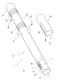
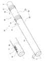
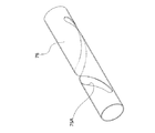
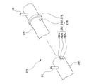
本実施形態に係る内視鏡装置1は、所謂側視型のものであって、図1から図3に示すように、照明部2、観察レンズ3及び図示しないCCDが配された内視鏡先端部5が先端に配されて、細長で可撓性を有するとともに湾曲操作可能な挿入部6と、挿入部6を湾曲操作させるジョイスティック7が配された操作部8と、CCDにより撮像された図示しない観察対象物を画像表示させる表示部10が配された装置本体11と、空気や水等の冷却用流体を流通させて挿入部6の先端側を冷却する内視鏡用冷却装置12とを備えている。
A first embodiment according to the present invention will be described with reference to FIGS.
The endoscope apparatus 1 according to the present embodiment is of a so-called side view type, and as shown in FIGS. 1 to 3, an endoscope provided with an
内視鏡用冷却装置12は、挿入部6に対して相対移動可能に挿入部6の外周面との間に冷却用流体が流れる挿入部流路13を形成して挿入部6の先端側に装着されるシース15と、挿入部流路13に冷却用流体を供給して回収する流体流通部16と、挿入部流路13を流れる冷却用流体がシース15の端部から排出されるのを規制する封止部17と、シース15の側面に配された観察窓18とを備えている。
The
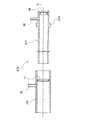
シース15は、金属部材からなり先端が開口されて挿入部6との間に挿入部流路13を形成し、先端からシース15の中心軸線C方向に向かって延びる切り欠き部20Aが形成された略円形断面の内シース20と、金属部材からなり先端が封止され、内シース20に対して相対移動可能に内シース20の外周面との間に冷却用流体が流れるシース流路21を形成する略円形断面の外シース22と、外シース22の基端側に配されてシース流路21に冷却用流体を流通させたときに冷却用流体が外シース22の基端から排出されるのを規制するシース封止部23とを備えている。挿入部流路13とシース流路21とは、内シース20の先端で連通されている。
The
内シース20は、外シース22が装着された際に外シース22の基端から所定の長さで基端側が突出可能な長さとなっている。内シース20の基端には、後述する第一接続リング37を螺合させるための第一おねじ部25が設けられている。
The
観察窓18は、切り欠き部20Aよりも小さく長孔状に形成されて外シース22の先端側の側面に配されている。切り欠き部20A及び観察窓18は、内シース20と外シース22とを嵌合させた際、切り欠き部20A及び観察窓18を通して挿入部6先端に配された照明部2及び観察レンズ3を視認可能な大きさとなっている。観察窓18には透明なカバーガラス26が接着されている。外シース22の基端には、後述する第二接続リング40を螺合させるための第二おねじ部27が設けられている。
The
流体流通部16は、冷却用流体の供給源28と、供給源28からの冷却用流体を挿入部流路13に流入させるために、外シース22の基端から中心軸線C方向に突出して内シース20の基端側に径方向外方に突出して設けられた流体供給口30と、シース15内を循環した冷却用流体をシース流路21から排出するために外シース22の基端側に径方向外方に突出して設けられた流体排出口31と、供給源28と流体供給口30とを接続する供給配管32と、供給源28と流体排出口31とを接続する排出配管33とを備えている。
The
供給源28は、冷却用流体が貯留されるタンク35と、タンク35内の冷却用流体を供給配管32に供給するためのポンプ36とを備えている。
The
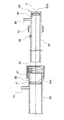
封止部17は、図3に示すように、内シース20の基端に設けられた第一おねじ部25と螺合された第一接続リング37と、第一接続リング37と内シース20の基端との間に挟持された第一Oリング38とを備えている。第一接続リング37の基端には、第一接続リング37と内シース20とを螺合することにより、第一Oリング38を内シース20の基端との間で中心軸線C方向に押圧するための第一鍔部37Aが、径方向内方に突出するようにして設けられている。なお、挿入部6と内シース20とは、第一Oリング38が押圧されて弾性変形することによって互いに固定される。ここで、第一Oリング38は、挿入部6と内シース20とを中心軸線C方向に互いにスライド可能、かつ、中心軸線C回りに互いに回転可能な状態で封止している。そのため、内視鏡先端部5に対して、切り欠き部20A及び観察窓18の位置が正確に位置合わせされる。なお、直視型の場合であっても、内視鏡先端部5とシースの先端面との位置決めが正確に調整される。
As shown in FIG. 3, the sealing
シース封止部23は、外シース22の基端に設けられた第二おねじ部27と螺合された第二接続リング40と、第二接続リング40と外シース22の基端との間に挟持された第二Oリング41とを備えている。第二接続リング40の基端には、第二接続リング40と外シース22とを螺合することにより、第二Oリング41を外シース22の基端との間で中心軸線C方向に押圧するための第二鍔部40Aが、径方向内方に突出するようにして設けられている。なお、内シース20と外シース22とは、第二Oリング41が押圧されて弾性変形することによって互いに固定される。ここで、第二Oリング41は、内シース20と外シース22とを中心軸線C方向に互いにスライド可能、かつ、中心軸線C回りに互いに回転可能な状態で封止している。
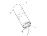
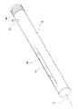
なお、直視型の内視鏡装置の場合、図4に示すように、内シースの切り欠き部を設ける代わりに、内シース42及び外シース43の先端がそれぞれ開口され、外シース43の先端面が観察窓45とされて直視型の挿入部46が視認可能とされたものでもよい。
The
In the case of a direct-view type endoscope apparatus, as shown in FIG. 4, instead of providing a cutout portion of the inner sheath, the distal ends of the
次に、本実施形態に係る内視鏡用冷却装置12及びこれを備える内視鏡装置1の使用方法及び作用について説明する。
まず、挿入部6の先端と内シース20の先端とが同一面上となるように内シース20と挿入部6とを嵌合し、第一接続リング37と内シース20の第一おねじ部25とを螺合して、第一鍔部37Aと内シース20の基端との間で第一Oリング38を押圧する。このとき、挿入部6の照明部2及び観察レンズ3が、内シース20の切り欠き部20A内に配されるようにしておく。この状態で、挿入部6と内シース20との間に形成された挿入部流路13が内シース20の基端側にて封止されるとともに、あわせて挿入部6と内シース20とが固定される。
Next, the usage method and operation of the
First, the
続いて、内シース20と外シース22とを嵌合し、観察窓18のカバーガラス26を介して挿入部6の照明部2や観察レンズ3が見えるように、第二接続リング40と外シース22の第二おねじ部27とを螺合して、第二鍔部40Aと外シース22の基端との間で第二Oリング41を押圧する。この状態で、内シース20と外シース22との間に形成されたシース流路21が外シース22の基端側にて封止されるとともに、あわせて内シース20と外シース22とが固定される。なお、先に内シース20と外シース22とを嵌合させてから、内シース20と挿入部6とを嵌合させてもよい。
Subsequently, the
次に、供給源28のポンプ36を駆動して冷却用流体をタンク35からシース15に送出する。即ち、冷却用流体は、供給配管32を介して流体供給口30から挿入部流路13に流入する。このとき、流体供給口30よりも内シース20の基端側に第一Oリング38が配されているので、冷却用流体は、挿入部流路13をシース15の先端側に向って流れ、内シース20先端の開口部分から外シース22と内シース20との先端面間に放出される。
Next, the
冷却用流体は、次にシース流路21に流入して、シース15の基端側に向かって流れる。このとき、流体排出口31が、外シース22に設けられた第二Oリング41よりも先端側に配されているので、冷却用流体は、流体排出口31から排出配管33に導入される。こうして、排出配管33からタンク35に戻った冷却用流体は、再び上述した経路を循環する。
The cooling fluid then flows into the
この状態で挿入部6をシース15とともに図示しない観察対象物の内部に挿入し、外シース22の観察窓18のカバーガラス26及び内シース20の切り欠き部20Aを介して照明部2から照明光を観察対象物に照射し、観察レンズ3を介してCCDにその状態を撮像させて表示部10に表示させる。このとき、シース15の周囲が高温状態でも、冷却用流体によって挿入部6先端が冷却されているので、挿入部6を介して内部に配された不図示のCCDカメラ等の温度上昇が抑えられる。
In this state, the
ここで、表示部10にて観察位置が最適な位置ではないと判断した場合には、第二接続リング40を把持しながら第二Oリング41の押圧変形によって内シース20との間に生じた摩擦力よりも大きな力を加えて、外シース22と内シース20とを中心軸線C方向に相対移動させる。このとき、観察窓18と挿入部6との相対位置が変化して、所望の観察画像が得られる。
観察が終了した際には、挿入部6及びシース15をともに観察対象物から取り出し、内視鏡用冷却装置12の供給源28のポンプ36の駆動を停止する。
Here, when it is determined by the
When the observation is completed, both the
この内視鏡用冷却装置12及びこれを備える内視鏡装置1によれば、シース15を内視鏡装置1の挿入部6に装着した状態で、挿入部流路13に冷却用流体を導入して挿入部6と内シース20との間の空間に流通させ、シース流路21に入ってさらに内シース20と外シース22との間のシース空間に冷却用流体を流通して外シース22から流体流通部16に排出させることにより、冷却用流体を循環させることができ、挿入部6の先端側を冷却することができる。この際、押圧された第二Oリング41の摩擦力以上の軸力を加えることにより、外シース22と挿入部6との相対位置を調整することができ、挿入部6の先端と観察窓18とが好適な位置になるように調整することができる。
According to the
次に、第2の実施形態について図5及び図6を参照しながら説明する。
なお、上述した第1の実施形態と同様の構成要素には同一符号を付すとともに説明を省略する。
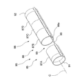
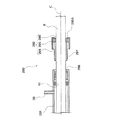
第2の実施形態と第1の実施形態との異なる点は、本実施形態に係る内視鏡用冷却装置50が、内シース51と外シース52との相対位置を調整する位置決め部53を備えているとした点である。
Next, a second embodiment will be described with reference to FIGS.
In addition, the same code | symbol is attached | subjected to the component similar to 1st Embodiment mentioned above, and description is abbreviate | omitted.
The difference between the second embodiment and the first embodiment is that the
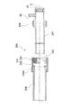
位置決め部53は、流体供給口30よりも先端側となる内シース51の所定位置に形成された位置決め用おねじ部55と、位置決め用おねじ部55の近傍で、位置決め用おねじ部55よりも先端側に内シース51の径方向外方に突設された凸部材56と、外シース52の鍔部52Aに回転自在に係合された位置決め用接続リング57と、外シース52の基端の内周面に設けられて、凸部材56が係合されるキー溝58とを備えている。キー溝58は、内シース51と外シース52との相対回転位置を、例えば、流体供給口30と流体排出口31とが同一平面上に並ぶように、所定の決められた位置に設けられている。この場合、冷却用流体の出入口が同一平面上となるので、供給配管32や排出配管33が複雑に絡んだりするのが抑えられる。特に、側視型の場合には、切り欠き部20A及び観察窓18の互いのずれがなくなる。
位置決め用接続リング57の内周面には、位置決め用おねじ部55と螺合可能な位置決め用めねじ部60が設けられている。
The positioning
On the inner peripheral surface of the
封止部17は、第1の実施形態と同様の構成となっているが、第一Oリング38は、内シース51の基端側に径方向内方に突出して設けられたOリング係止部51Aに接触して配されている。シース封止部61は、外シース52の内周面に形成された第二凹溝52a内に配された第二Oリング41のみを備えている。
The sealing
次に、本実施形態に係る内視鏡用冷却装置50及びこれを備える内視鏡装置62の使用方法、及び作用について説明する。
まず、第1の実施形態と同様に、図示しない挿入部の先端面と内シース51の先端面とが同一面上となるように内シース51と挿入部とを嵌合する。この際、第一Oリング38がOリング係止部51Aと第一鍔部37Aとの間で押圧変形され、挿入部と内シース51との間の図示しない挿入部流路が内シース51の基端にて封止される。このとき、挿入部6と内シース51とは、第一Oリング38によって、スライド、かつ回転可能に封止されている。
Next, the usage method and operation of the
First, as in the first embodiment, the
続いて、内シース51と外シース52とを嵌合して、凸部材56とキー溝58とを係合させる。そして、位置決め用接続リング57の位置決め用めねじ部60と内シース51の位置決め用おねじ部55とを所定長さで螺合させる。これによって、内シース51と外シース52とのそれぞれの先端の距離が所定の距離dに固定される。このとき、第二Oリング41が押圧変形されるので、内シース51と外シース52との間に形成される図示しないシース流路が外シース52の基端側にて封止される。
Subsequently, the
次に、第1の実施形態と同様に、冷却用流体をシース63内で循環させる。この状態で挿入部をシース63とともに図示しない観察対象物の内部に挿入し、観察対象物を観察する。このとき、シース63の周囲が高温状態でも、冷却用流体によって挿入部の先端側が冷却される。 Next, as in the first embodiment, the cooling fluid is circulated in the sheath 63. In this state, the insertion portion is inserted into an observation object (not shown) together with the sheath 63, and the observation object is observed. At this time, even if the periphery of the sheath 63 is in a high temperature state, the distal end side of the insertion portion is cooled by the cooling fluid.
ここで、表示部10にて観察位置が最適な位置ではないと判断した場合には、位置決め用接続リング57を回転して位置決め用めねじ部60と内シース51の位置決め用おねじ部55との螺合長さを調整する。これによって、外シース52と内シース51とが中心軸線C方向に相対移動して、図示しない観察窓と挿入部6との相対位置が変化し、所望の観察画像が得られる。
Here, when the
この内視鏡用冷却装置50及びこれを備える内視鏡装置62によれば、位置決め用接続リング57を回転して内シース51との螺合状態を調整することによって、観察窓18と挿入部の先端との相対位置を好適な位置に調整することができる。
According to the
なお、図7及び図8に示すように、封止部66が、シース封止部61と同様に、内シース67の内周面に形成された第一凹溝67a内に配された第一Oリング38のみを備えているとしてもよい。
As shown in FIGS. 7 and 8, the sealing
次に、第3の実施形態について図9から図11を参照しながら説明する。
なお、上述した他の実施形態と同様の構成要素には同一符号を付すとともに説明を省略する。
第3の実施形態と上記他の実施形態との異なる点は、本実施形態に係る内視鏡用冷却装置70の観察窓71が外シース72の側面に長孔状に設けられ、シース73が、外シース72の先端側に回転自在に配された外筒部75を備えているとした点である。
Next, a third embodiment will be described with reference to FIGS.
In addition, the same code | symbol is attached | subjected to the component similar to other embodiment mentioned above, and description is abbreviate | omitted.
The difference between the third embodiment and the other embodiments described above is that the
観察窓71は、中心軸線C方向に沿って延びて外シース72に設けられている。なお、観察窓の長手方向は、必ずしも中心軸線C方向と一致していなくても構わない。観察窓71にはカバーガラス76が装着されている。
The
外筒部75は弾性変形可能な部材からなり、観察窓71の長手方向に対して螺旋溝75Aが設けられ、観察窓71と交差した際に観察窓71の一部を露出可能になっている。
外筒部75の中心軸線C方向の長さは、観察窓71の長手方向の長さよりも長くなるように決められている。
The
The length of the
次に、本実施形態に係る内視鏡用冷却装置70及びこれを備える内視鏡装置77の使用方法、及び作用について説明する。
まず、第1の実施形態と同様に、図示しない内シースと挿入部とを嵌合して、挿入部の先端と内シースの先端とが同一面上となるように固定する。
Next, the usage method and operation of the
First, similarly to the first embodiment, an inner sheath (not shown) and an insertion portion are fitted, and fixed so that the distal end of the insertion portion and the distal end of the inner sheath are on the same plane.
続いて、内シースと外シース72とを嵌合し、第1の実施形態と同様に、観察窓71を介して図示しない内視鏡先端部の照明部や観察レンズが見えるように、内シースと外シース72とを所定の相対位置に固定する。そして、外筒部75と外シース72とを嵌合させ、外筒部75の弾性力により外筒部75を外シース72に位置決めする。そして、外筒部75と外シース72とを相対回転して、観察窓71を介して螺旋溝75Aから照明部及び観察レンズがシース73の外側から視認できる位置になるように調整する。
Subsequently, the inner sheath and the
次に、第1の実施形態と同様に、冷却用流体をシース73内で循環させる。この状態で挿入部をシース73とともに図示しない観察対象物の内部に挿入し、冷却用流体によって挿入部の先端側が冷却された状態で観察対象物を観察する。
Next, as in the first embodiment, the cooling fluid is circulated in the
ここで、シース73に対して挿入部を進退移動して観察場所を変更した場合には、内視鏡先端部の照明部及び観察レンズが外筒部75の螺旋溝75Aから外れ、螺旋溝75A以外の部分で外筒部75に覆われてしまう。そこで、外筒部75をシース73回りに回転することにより、観察窓71に対する螺旋溝75Aの位置が移動して、照明部及び観察レンズの位置と螺旋溝75Aの位置とが一致するように調整する。
Here, when the observation portion is changed by moving the insertion portion forward and backward with respect to the
この内視鏡用冷却装置70及び内視鏡装置77によれば、外筒部75を外シース72に対して回転することにより、螺旋溝75Aから外部に露出される観察窓71の位置を、シース73の中心軸線C方向に相対移動させることができる。従って、挿入部とシース73とを相対移動させなくても観察位置を変更することができる。この際、観察窓71が長孔状に形成されていても、螺旋溝75Aと交差しない部分では外筒部75が観察窓71を覆うので、余計な光が外方から観察窓71に入射してしまうのを好適に抑えることができ、観察性能を向上することができる。
According to the
次に、第4の実施形態について図12を参照しながら説明する。
なお、上述した他の実施形態と同様の構成要素には同一符号を付すとともに説明を省略する。
第4の実施形態と第3の実施形態との異なる点は、本実施形態に係る内視鏡用冷却装置80の外筒部81に、螺旋溝75Aの代わりに、図示しない観察窓と交差するように観察窓の長手方向に対して螺旋状に並んで観察窓の一部を露出させる複数の孔81A,81B,81Cが設けられているとした点である。
Next, a fourth embodiment will be described with reference to FIG.
In addition, the same code | symbol is attached | subjected to the component similar to other embodiment mentioned above, and description is abbreviate | omitted.
The difference between the fourth embodiment and the third embodiment is that the
各孔81A,81B,81Cは、図示しない外シースの中心軸線C方向を長手方向とする長孔状に形成されている。各孔81A,81B,81Cの長さは、内視鏡先端部5と略同一の長さとされ、幅は観察窓よりも狭い幅になっている。外筒部81の表面には、孔81A,81B,81Cと交差しない位置に、拡開可能なスリット82が中心軸線Cに沿って設けられている。
Each
この内視鏡用冷却装置80及び内視鏡装置83によれば、外筒部81と外シースとを嵌合させる際、スリット82を拡げて外筒部81を弾性変形させることができ、観察窓と孔81A,81B,81Cの何れかが一致するように外筒部81を外シースに対して相対回転させることによって、第3の実施形態と同様の作用・効果を奏することができる。
According to the
次に、第5の実施形態について図13を参照しながら説明する。
なお、上述した他の実施形態と同様の構成要素には同一符号を付すとともに説明を省略する。
第5の実施形態と第3及び第4の実施形態との異なる点は、本実施形態に係る内視鏡用冷却装置85のシース86が、外筒部75,81の代わりに、図示しない外シースに対して中心軸線C方向に互いに進退自在に配列されて、図示しない観察窓の一部のみを露出させる複数の短管部87A,87B,87C,87Dを有する短管部列88を備えているとした点である。
Next, a fifth embodiment will be described with reference to FIG.
In addition, the same code | symbol is attached | subjected to the component similar to other embodiment mentioned above, and description is abbreviate | omitted.
The difference between the fifth embodiment and the third and fourth embodiments is that the
短管部列88は、さらに、各短管部87A,87B,87C,87Dを連結するための連結ワイヤ90と、連結ワイヤ90の先端が固定される短管状の前側固定部91と、連結ワイヤ90の基端が固定される後側固定部92とを備えている。短管部87A,87B,87C,87Dは、前側固定部91と後側固定部92との間に挟まれて一列に並べられて配されている。
The short
短管部87A,87B,87C,87Dには、連結ワイヤ90が各短管部に対して進退自在に貫通される貫通孔部88aが中心軸線C方向にそれぞれ設けられている。前側固定部91、後側固定部92、各短管部の内径は、外シースの外径と略同一の大きさとされて、外シースと嵌合可能となっている。
The
連結ワイヤ90は、図示しない観察窓の長手方向の長さよりも長くなっており、両端部が前側固定部91及び後側固定部92にそれぞれ接続されている。前側固定部91、後側固定部92、各短管部の中心軸線C方向長さ及び各短管部の数は、これらを一列に並べたときの中心軸線C方向の長さが、連結ワイヤ90よりも観察窓の長手方向の長さ分だけ短くなるように決められている。従って、各短管部の中心軸線C方向長さ及び各短管部の数を調整することにより、何れかの短管部間に、隙間93が所定の長さで形成されるようになっている。隙間93の長手方向の長さは、図示しない内視鏡先端部の照明部や観察レンズの長さよりも若干大きく、観察の妨げにならない長さであればよい。
The connecting
ここで、短管部列の長手方向の長さを一定とした状態で、各短管部の長手方向の長さを短くするとともに、短管部の数を増やした場合には、観察窓に対する隙間93の位置をより細かく調整することができる。一方、細かい調整が不要の場合には、逆に短管部の長手方向の長さを長くするとともに、短管部の数を少なくしてもよい。
Here, when the length in the longitudinal direction of each short tube portion is shortened and the number of short tube portions is increased while keeping the length in the longitudinal direction of the short tube portion row constant, The position of the
次に、本実施形態に係る内視鏡用冷却装置85及びこれを備える内視鏡装置95の使用方法、及び作用について説明する。
まず、第3の実施形態と同様に、図示しない内シースと挿入部とを嵌合し、内シースと外シースとを嵌合して、図示しない観察窓を介して図示しない照明部や観察レンズが見えるように、内シースと外シースとを所定の相対位置に固定する。
Next, the usage method and operation of the
First, similarly to the third embodiment, an inner sheath (not shown) and an insertion portion are fitted, an inner sheath and an outer sheath are fitted, and an illumination unit and an observation lens (not shown) are connected via an observation window (not shown). So that the inner sheath and the outer sheath are fixed at a predetermined relative position.
続いて、短管部列88を外シースと嵌合させて外シースに固定する。そして、短管部87A,87B,87C,87Dを外シースに沿って進退移動して何れかの短管部間に隙間93を形成し、観察窓を介して照明部及び観察レンズがシース86の外側から視認できる位置になるように調整しておく。
Subsequently, the short
次に、第1の実施形態と同様に、冷却用流体をシース86内で循環させる。この状態で図示しない挿入部をシース86とともに図示しない観察対象物の内部に挿入し、冷却用流体によって挿入部の先端側が冷却された状態で観察対象物を観察する。
Next, similarly to the first embodiment, the cooling fluid is circulated in the
ここで、シース86に対して挿入部を進退移動して観察場所を変更した場合には、内視鏡先端部の照明部及び観察レンズが短管部間の隙間93から外れ、別の短管部に覆われてしまう。そこで、所定の短管部を連結ワイヤ90に沿って外シースに対して進退移動することにより、観察窓に対する隙間93の相対位置が変化して、照明部及び観察レンズの位置と隙間93の位置とを一致させる。
Here, when the observation portion is changed by moving the insertion portion forward and backward with respect to the
この内視鏡用冷却装置85及び内視鏡装置95によれば、短管部列88を装着して外シースに対して短管部87A,87B,87C,87Dを進退させることによって、第3及び第4の実施形態と同様の効果を奏することができる。
According to the
次に、第6の実施形態について図14を参照しながら説明する。
なお、上述した他の実施形態と同様の構成要素には同一符号を付すとともに説明を省略する。
第6の実施形態と第1の実施形態との異なる点は、本実施形態に係る内視鏡用冷却装置100のシース101の外シース102が、ガラス等の透明部材からなる透明シース103と、透明シース103に進退及び回転自在に装着された保護シース105とを備え、保護シース105の側面に透明シース103の一部を露出させる孔が観察窓106として設けられているとした点である。
Next, a sixth embodiment will be described with reference to FIG.
In addition, the same code | symbol is attached | subjected to the component similar to other embodiment mentioned above, and description is abbreviate | omitted.
The difference between the sixth embodiment and the first embodiment is that the
透明シース103の先端は封止されており、基端には、流体排出口31が設けられた口金107が接続されている。保護シース105の先端も封止されており、透明シース103と略同一の長さとなっている。保護シース105の先端の所定位置には、観察窓106が形成されている。ただし、観察窓106には、第1の実施形態のようなカバーガラスは接着されておらず、貫通孔となっている。
The distal end of the
次に、本実施形態に係る内視鏡用冷却装置100及びこれを備える内視鏡装置108の使用方法、及び作用について説明する。
まず、第1の実施形態と同様に、図示しない内シースと挿入部とを嵌合した後、内シースと透明シース103とを嵌合する。そして、透明シース103と保護シース105とをさらに嵌合する。この際、観察窓106を介して図示しない内視鏡先端部の照明部や観察レンズがシース101の外側から見えるように、内シース及び保護シース105を所定の位置に固定する。
Next, the usage method and operation of the
First, similarly to the first embodiment, after fitting an inner sheath (not shown) and an insertion portion, the inner sheath and the
その後、第1の実施形態と同様に、冷却用流体をシース101内で循環させる。この状態で挿入部をシース101とともに図示しない観察対象物の内部に挿入し、冷却用流体によって挿入部の先端側が冷却された状態で観察対象物を観察する。
Thereafter, the cooling fluid is circulated in the
この内視鏡用冷却装置100及び内視鏡装置108によれば、外シース102からガラスの接着部分をなくすことができ、高温にも耐えられる接着剤を用意しなくても観察可能なものを提供することができる。
According to the
次に、第7の実施形態について図15を参照しながら説明する。
なお、上述した他の実施形態と同様の構成要素には同一符号を付すとともに説明を省略する。
第7の実施形態と第1の実施形態との異なる点は、本実施形態に係る内視鏡用冷却装置110が、内シース111と外シース112との相対回転を規制する回転規制部113を備えているとした点である。
Next, a seventh embodiment will be described with reference to FIG.
In addition, the same code | symbol is attached | subjected to the component similar to other embodiment mentioned above, and description is abbreviate | omitted.
The difference between the seventh embodiment and the first embodiment is that the
回転規制部113は、内シース111の基端側から径方向外方に突出して設けられた凸部115と、外シース112の基端から先端に向かって中心軸線C方向に所定の長さで設けられて凸部115が係合される溝部116とを備えている。内シース111及び外シース112の基端の内周面には、封止部及びシース封止部として、流体供給口30及び流体排出口31よりも先端側となる所定の位置に、それぞれ図示しないOリングが配されている。
The
外シース112に配された観察窓117は、先端面に設けられた外側直視窓(直視窓)117A及び側面に設けられた外側側視窓(側視窓)117Bを備えている。外側直視窓117Aには直視用カバーガラス118が、また、外側側視窓117Bには側視用カバーガラス120がそれぞれ配されている。
内シース111の先端側の側面には、外側側視窓117Bと相似形で外側側視窓117Bよりも小さい内側側視窓(側視窓)121が開口して設けられ、先端面には、内側直視窓(直視窓)122が開口して設けられている。
外側側視窓117Bと内側側視窓121とは、内シース111と外シース112とを位置決めした際に、ずれが生じないような大きさとなっている。
The
An inner side viewing window (side viewing window) 121 that is similar to the outer
The outer
溝部116は、外シース112の基端から先端側に向かって中心軸線C方向に有限長さで延びて形成されている。溝部116の幅は、凸部115と略同一の大きさとなっている。溝部116の長さは、凸部115と溝部116とが係合された状態で凸部115が溝部116の先端位置まで移動したときに凸部115の移動が規制され、内シース111と外シース112との先端面が所定の間隔となるようになっている。
The
次に、本実施形態に係る内視鏡用冷却装置110及びこれを備える内視鏡装置123の使用方法、及び作用について説明する。
まず、第1の実施形態と同様に、内シース111と挿入部6とを嵌合した後、内シース111と外シース112とを嵌合する。この際、外シース112の溝部116と内シース111の凸部115とを係合させながら、内シース111と外シース112とを相対移動させる。
Next, the usage method and operation of the
First, as in the first embodiment, after the
このとき、凸部115を溝部116の先端に当接させることにより、外側側視窓117Bと内側側視窓121とが重なる。これによって、外側側視窓117Bと内側側視窓121とを介して図示しない内視鏡先端部の照明部や観察レンズが外シース112の外側から視認できるように、内シース111と外シース112とが所定の位置に固定される。
At this time, the outer
その後、第1の実施形態と同様に、冷却用流体をシース125内で循環させる。この状態で挿入部をシース125とともに図示しない観察対象物の内部に挿入し、冷却用流体によって挿入部の先端側が冷却された状態で観察対象物を観察する。
Thereafter, the cooling fluid is circulated in the
この内視鏡用冷却装置110及び内視鏡装置123によれば、特に、側視型の内視鏡装置に対して、内シース111と外シース112とが相対的に回転移動して挿入部6の先端側と観察窓117との位置ずれが生じるのを好適に抑えることができる。
According to the
次に、第8の実施形態について図16を参照しながら説明する。
なお、上述した他の実施形態と同様の構成要素には同一符号を付すとともに説明を省略する。
第8の実施形態と第7の実施形態との異なる点は、本実施形態に係る内視鏡用冷却装置130の内シース131及び外シース132が、ともに断面略矩形状とされ、各シース131,132の角部133が回転規制部134とされた点である。
Next, an eighth embodiment will be described with reference to FIG.
In addition, the same code | symbol is attached | subjected to the component similar to other embodiment mentioned above, and description is abbreviate | omitted.
The difference between the eighth embodiment and the seventh embodiment is that both the
外シース132に配された観察窓135は、先端面に設けられた矩形状の外側直視窓135A及び側面に設けられた矩形状の外側側視窓135Bを備えている。外側直視窓135Aには矩形状の直視用カバーガラス136が、また、外側側視窓135Bには矩形状の側視用カバーガラス137がそれぞれ配されている。内シース131の先端側には、内側直視窓138A及び内側側視窓138Bがそれぞれ開口して設けられている。
The
この内視鏡用冷却装置130及び内視鏡装置139によれば、内側側視窓138Bと外側側視窓135Bとの位置が合うように、内シース131と外シース132とを嵌合させることによって、両者の角部133が内シース131と外シース132との相対回転を規制することができ、内側側視窓138Bと外側側視窓135Bとが位置ずれしてしまうのを抑えることができる。なお、内シース131と外シース132との相対回転による、外側側視窓135Bと内側側視窓138Bとの位置ずれを防ぐため、角部133ではなく、内シース及び外シースの一部を変形して、相対回転しない形状としても構わない。
According to the
次に、第9の実施形態について図17を参照しながら説明する。
なお、上述した他の実施形態と同様の構成要素には同一符号を付すとともに説明を省略する。
第9の実施形態と第7の実施形態との異なる点は、本実施形態に係る内視鏡用冷却装置140の観察窓117が、外シース141に着脱可能に装着されるとした点である。
Next, a ninth embodiment will be described with reference to FIG.
In addition, the same code | symbol is attached | subjected to the component similar to other embodiment mentioned above, and description is abbreviate | omitted.
The difference between the ninth embodiment and the seventh embodiment is that the
即ち、外シース141に着脱可能に装着されて外側直視窓117Aを覆い、かつ、外側側視窓117Bを露出させる第一短管142と、外シース141に着脱可能に装着されて外側側視窓117Bを覆い、かつ、外側直視窓117Aを露出させる第二短管143とが内視鏡用冷却装置140に設けられている。
That is, the first
第一短管142の先端は封止されており、第二短管143の先端は開口端となっている。また、第一短管142のほうが第二短管143よりも中心軸線C方向に短くなっている。
外側側視窓117Bよりも先端側の外シース141の外周面には、おねじ部145が設けられている。そして、第一短管142の基端側及び第二短管143の先端側の内周面には、おねじ部145と螺合可能なめねじ部146が設けられている。
The tip of the first
A
次に、本実施形態に係る内視鏡用冷却装置140及びこれを備える内視鏡装置147の使用方法、及び作用について説明する。
図示しない内シースと外シース141とを嵌合する際、内視鏡が側視型の場合には、外シース141のめねじ部146に第一短管142のおねじ部145を螺合させて第一短管142を外シース141の先端に装着する。このとき、外側直視窓117Aは第一短管142に覆われてしまうが、外側側視窓117Bは、第一短管142に覆われずに外部に露出した状態となる。
Next, a method of using the
When fitting the inner sheath (not shown) and the
一方、内視鏡が直視型の場合には、外シース141のめねじ部146に第二短管143のおねじ部145を螺合させて第二短管143を外シース141の先端に装着する。このとき、外側側視窓117Bは第二短管143に覆われてしまうが、外側直視窓117Aは、第二短管143に覆われずに外部に露出した状態となる。
その後は、上述した他の実施形態と同様に冷却を行う。
On the other hand, when the endoscope is a direct view type, the second
Thereafter, cooling is performed as in the other embodiments described above.
この内視鏡用冷却装置140及び内視鏡装置147によれば、外シース141に第一短管142を装着することにより、直視方向からの光の影響を減らして側視型による観察を好適に行うことができる。また、外シース141に第二短管143を装着することにより、側視方向からの光の影響を減らして直視型による観察を好適に行うことができる。
According to the
次に、第10の実施形態について図18を参照しながら説明する。
なお、上述した他の実施形態と同様の構成要素には同一符号を付すとともに説明を省略する。
第10の実施形態と第9の実施形態との異なる点は、本実施形態に係る内視鏡用冷却装置150の外シース151には、おねじ部145の代わりに、外周面から径方向外方に突出した突起部152が設けられ、第一短管153及び第二短管155には、めねじ部146の代わりに、突起部152が係合可能な溝部156A,156Bが設けられているとした点である。
Next, a tenth embodiment will be described with reference to FIG.
In addition, the same code | symbol is attached | subjected to the component similar to other embodiment mentioned above, and description is abbreviate | omitted.
The difference between the tenth embodiment and the ninth embodiment is that the
溝部156Aは第一短管153の基端から、及び、溝部156Bは第二短管155の基端からそれぞれの先端側に向かって中心軸線C方向に有限長さに延びて形成されている。溝部156Aよりも溝部156Bのほうが長く形成されている。溝部156A,156Bの幅は、基端側は突起部152よりも小さい幅とされ、突起部152が係合された際には、溝部156A,156Bの幅が拡開可能となっている。
The
溝部156A,156Bの先端は、突起部152と略同一の大きさの幅を有する固定部157となっており、突起部152が固定部157の位置に配されたときには、溝部156A,156Bの幅が狭まって突起部152の溝部156A,156B内の移動が規制されるようになっている。
The tips of the
次に、本実施形態に係る内視鏡用冷却装置150及びこれを備える内視鏡装置158の使用方法、及び作用について説明する。
図示しない内シースと外シース151とを嵌合する際、内視鏡が側視型の場合には、外シース151の突起部152と第一短管153の溝部156Aとを係合させる。この際、溝部156Aが拡開されながら突起部152が溝部156Aの先端側に相対移動する。突起部152が固定部157まで相対移動したとき、第一短管153が外シース151の先端に装着される。このとき、外側直視窓117Aは第一短管153に覆われてしまうが、外側側視窓117Bは、第一短管153に覆われずに外部に露出した状態となる。
Next, the usage method and operation of the
When the inner sheath (not shown) and the
一方、内視鏡が直視型の場合には、外シース151の突起部152と第二短管155の溝部156Bとを係合させて、第一短管153の場合と同様に第二短管155を外シース151の先端に装着する。このとき、外側側視窓117Bは第二短管155に覆われてしまうが、外側直視窓117Aは、第二短管155に覆われずに外部に露出した状態となる。こうして、第9の実施形態と同様に冷却及び観察を行う。
On the other hand, when the endoscope is a direct view type, the
この内視鏡用冷却装置150及び内視鏡装置158によれば、第9の実施形態と同様の効果を奏することができる。
According to the
次に、第11の実施形態について図19を参照しながら説明する。
なお、上述した他の実施形態と同様の構成要素には同一符号を付すとともに説明を省略する。
第11の実施形態と第1の実施形態との異なる点は、本実施形態に係る内視鏡用冷却装置160の外シース161が、先端に装着されたガラスからなるガラス短管162を備えているとした点である。
Next, an eleventh embodiment will be described with reference to FIG.
In addition, the same code | symbol is attached | subjected to the component similar to other embodiment mentioned above, and description is abbreviate | omitted.
The difference between the eleventh embodiment and the first embodiment is that the
即ち、外シース161は、先端が開口され、基端に流体排出口31やシース封止部17が配された外シース本体163と、ガラス短管162とを備えている。そして、ガラス短管162が外シース本体163の先端に螺合されている。ガラス短管162は、内視鏡装置165の図示しない挿入部と図示しない内シースとを嵌合させ、さらに外シース161と嵌合させた際に、挿入部の観察レンズ及び照明部をガラス短管162の外側から視認可能な長さとなっている。なお、このガラス短管162に対して、第6の実施形態における保護シース105と同様の形状及び機能を有する保護管を装着しても構わない。
That is, the
次に、本実施形態に係る内視鏡用冷却装置160及びこれを備える内視鏡装置165の使用方法、及び作用について説明する。
まず、ガラス短管162を外シース本体163に螺合させて外シース161とする。そして、挿入部6と図示しない内シースとを嵌合し、さらに内シースと外シース161とを嵌合する。この際、必要に応じて、上述した図示しない保護管をガラス短管162に被せる。
Next, the usage method and operation of the
First, the
その後は、上述した他の実施形態と同様に冷却を行う。
この内視鏡用冷却装置160及び内視鏡装置165によれば、第6の実施形態と同様の効果を奏することができる。特に、ガラス短管162に不具合があった場合、外シース161全体でなく、ガラス短管162のみを外シース本体163から取り外して修理・交換すればよいので、取り扱いをより容易にすることができる。なお、ガラス短管162と外シース本体163とを、着脱可能な接着剤によって接着して装着しても構わない。
Thereafter, cooling is performed as in the other embodiments described above.
According to the
次に、第12の実施形態について図20及び図21を参照しながら説明する。
なお、上述した他の実施形態と同様の構成要素には同一符号を付すとともに説明を省略する。
第12の実施形態と第11の実施形態との異なる点は、本実施形態に係る内視鏡用冷却装置170の観察窓171が、外シース172に着脱可能に装着されるとした点である。
Next, a twelfth embodiment will be described with reference to FIGS.
In addition, the same code | symbol is attached | subjected to the component similar to other embodiment mentioned above, and description is abbreviate | omitted.
The difference between the twelfth embodiment and the eleventh embodiment is that the
観察窓171は、外側直視窓171Aと外側側視窓171Bとを備えている。
外シース172は、外シース本体175と、外側直視窓171Aが配されて外シース本体175の先端に着脱可能に装着される直視用変換アダプタ176と、外側側視窓171Bが配されて外シース本体175の先端に着脱可能に装着される側視用変換アダプタ177とを備えている。外シース本体175の先端の内周面には、装着用めねじ部178が設けられている。装着用めねじ部178の基端には、装着用凹溝175aが形成され、装着用Oリング180が配されている。
The
The
直視用変換アダプタ176及び側視用変換アダプタ177の基端側外周面は、装着用Oリング180が接触されるシール面181となっており、シール面181よりも先端側には、装着用めねじ部178と螺合可能な装着用おねじ部182が形成されている。直視用変換アダプタ176は、外側直視窓171Aに直視用カバーガラス118が接着されて先端側が封止されている。側視用変換アダプタ177は、外側側視窓171Bに側視用カバーガラス120が接着されて先端側が封止されている。
The outer peripheral surface of the proximal end of the direct-
次に、本実施形態に係る内視鏡用冷却装置170及びこれを備える内視鏡装置183の使用方法、及び作用について説明する。
まず、直視用変換アダプタ176又は側視用変換アダプタ177を外シース本体175に螺合させて外シース172とする。そして、挿入部6と図示しない内シースとを嵌合し、さらに内シースと外シース172とを嵌合する。この際、装着用Oリング180がシール面181に押圧されて変形して外シース172の先端が封止される。
Next, the usage method and operation of the
First, the direct
その後は、上述した他の実施形態と同様に冷却を行う。
この内視鏡用冷却装置170及び内視鏡装置183によれば、内視鏡装置182が直視型か又は側視型かに応じて直視用変換アダプタ176又は側視用変換アダプタ177を交換することによって、異なる観察窓を設けることができる。この際、外シース172全体でなく、一番高熱に晒される先端部分のみを交換することができ、装置全体の取り扱いを容易にするとともに、製造コストを低減させることができる。
Thereafter, cooling is performed as in the other embodiments described above.
According to the
次に、第13の実施形態について図22を参照しながら説明する。
なお、上述した他の実施形態と同様の構成要素には同一符号を付すとともに説明を省略する。
第13の実施形態と第2の実施形態との異なる点は、本実施形態に係る内視鏡用冷却装置190の内シース191が、外シース192と嵌合される先端側の小径部191Aと、外シース192の外径と略同一の大きさの外径とされ、外シース192と嵌合された際に外シース192の基端よりもさらに基端に突出する大径部191Bとを備えているとした点である。また、位置決め部193が、挿入部6の貫通を阻止するとともに、挿入部6からの観察を可能とする孔195aが形成されて内シース191の先端に設けられた規制部195と、内シース191の小径部191Aと大径部191Bとの境界に設けられた段部196とを備えているとした点である。
Next, a thirteenth embodiment will be described with reference to FIG.
In addition, the same code | symbol is attached | subjected to the component similar to other embodiment mentioned above, and description is abbreviate | omitted.
The difference between the thirteenth embodiment and the second embodiment is that the
段部196の小径部191A側の外周面には、位置決め用おねじ部197が設けられ、外シース192の基端の内周面には、位置決め用おねじ部197と螺合される位置決め用めねじ部198が設けられている。ここで、封止部17は第1の実施形態と同様の構成となっており、シース封止部61は、第2の実施形態と同様の構成となっている。
A positioning
次に、本実施形態に係る内視鏡用冷却装置190及び内視鏡装置199の使用方法、及び作用について説明する。
まず、挿入部6と内シース191とを嵌合する。この際、挿入部6の先端面が内シース191の規制部195に当接するまで押し込むことにより、内シース191と挿入部6とが位置決めされる。
Next, the usage and operation of the
First, the
続いて内シース191の小径部191Aと外シース192とを嵌合させる。そして、両者を相対回転させて位置決め用おねじ部197と位置決め用めねじ部198とを所定の長さで螺合する。こうして、内シース191と外シース192とが位置決めされる。
Subsequently, the
その後は、上述と同様に冷却を行う。
この内視鏡用冷却装置190及び内視鏡装置199によれば、挿入部6を規制部195に当接させることによって、挿入部6と内シース191との先端面を確実に同一面上に位置決めすることができる。また、内シース191と外シース192とを相対回転させることによって、両者の相対位置を調整することができる。
Thereafter, cooling is performed in the same manner as described above.
According to the
次に、第14の実施形態について図23を参照しながら説明する。
なお、上述した他の実施形態と同様の構成要素には同一符号を付すとともに説明を省略する。
第14の実施形態と第13の実施形態との異なる点は、本実施形態に係る内視鏡用冷却装置200の位置決め部201が、内シース202の先端にて挿入部6の先端が当接可能な長さまで径方向内方に突出して設けられた一対の第一係止部203A,203Bと、外シース205の先端にて内シース202の先端が当接可能な長さまで径方向内方に突出して設けられた一対の第二係止部206A,206Bとを備えているとした点である。
Next, a fourteenth embodiment will be described with reference to FIG.
In addition, the same code | symbol is attached | subjected to the component similar to other embodiment mentioned above, and description is abbreviate | omitted.
The difference between the fourteenth embodiment and the thirteenth embodiment is that the
一対の第一係止部203A,203Bと一対の第二係止部206A,206Bとは、突出方向が中心軸線Cに対して互いに略直交するように配されている。なお、シース封止部23は、第1の実施形態と同様の構成となっている。
The pair of
次に本実施形態に係る内視鏡用冷却装置200及び内視鏡装置208の使用方法、及び作用について説明する。
まず、挿入部6と内シース202とを嵌合する際には、挿入部6の先端面が内シース202の一対の第一係止部203A,203Bに当接するまで押し込む。このとき、内シース202と挿入部6との先端面が略同一面上に位置決めされる。
Next, the usage method and operation of the
First, when the
続いて、内シース202と外シース205とを嵌合する。この際、内シース202の先端面が外シース205の一対の第二係止部206A,206Bに当接するまで押し込むことにより、内シース202と外シース205との先端面が略同一面上に位置決めされる。
その後は、上述と同様の冷却を行う。
この内視鏡用冷却装置200及び内視鏡装置208によれば、挿入部6と内シース202とを、及び、内シース202と外シース205とをそれぞれ好適な位置に容易に位置決めすることができる。
Subsequently, the
Thereafter, the same cooling as described above is performed.
According to the
次に、第15の実施形態について図24及び図25を参照しながら説明する。
なお、上述した他の実施形態と同様の構成要素には同一符号を付すとともに説明を省略する。
第15の実施形態と第3の実施形態との異なる点は、第3の実施形態では、外筒部75と外シース72とが回転自在に嵌合されていたのに対して、本実施形態に係る内視鏡用冷却装置210が、外筒部211と外シース212との位置決めのための外筒部位置決め部213を備えているとした点である。
Next, a fifteenth embodiment will be described with reference to FIGS.
In addition, the same code | symbol is attached | subjected to the component similar to other embodiment mentioned above, and description is abbreviate | omitted.
The difference between the fifteenth embodiment and the third embodiment is that, in the third embodiment, the
外筒部211には、第3の実施形態と同様の螺旋溝211Aが設けられている。また外筒部211の基端には、外筒部211を外シース212に対して相対回転させる際に把持する把持部211Bが設けられている。把持部211Bの内面には、外筒部211と外シース212との間に形成された隙間を封止して摩擦を発生させることにより、互いの位置を保持するための外筒Oリング215が配されている。なお、内シース51は、第2の実施形態と同様の構成となっている。
The outer
外筒部位置決め部213は、外シース212に配された流体排出口31よりも先端側の外周面に径方向外方に突設された外筒用凸部材216と、外筒用凸部材216が係合可能に外筒部211に設けられた外筒溝211Cとを備えている。
The outer cylinder
次に、本実施形態に係る内視鏡用冷却装置210及びこれを備える内視鏡装置217の使用方法、及び作用について説明する。
まず、第2の実施形態と同様に、内シース51と挿入部6とを嵌合して、内視鏡先端部5の先端と内シース51の先端とが略同一面上となるように固定する。
Next, the usage method and operation of the
First, as in the second embodiment, the
続いて、内シース51と外シース212とを嵌合し、第1の実施形態と同様に、観察窓71を介して照明部2や観察レンズ3が見えるように、内シース51と外シース212とを所定の相対位置に固定する。そして、外筒部211と外シース212と嵌合させ、外筒用凸部材216と外筒溝211Cとを係合させて、把持部211Bを把持しながら外筒部211を外シース212回りに回転して、観察窓171を介して螺旋溝211Aから照明部2及び観察レンズ3が外側から視認できる位置になるように調整する。
Subsequently, the
その後は、上述した他の実施形態と同様に冷却を行う。
この内視鏡用冷却装置210及びこれを備える内視鏡装置217によれば、第3の実施形態と同様の効果を奏することができる。
Thereafter, cooling is performed as in the other embodiments described above.
According to the
次に、第16の実施形態について図26を参照しながら説明する。
なお、上述した他の実施形態と同様の構成要素には同一符号を付すとともに説明を省略する。
第16実施形態と第2の実施形態との異なる点は、本実施形態に係る内視鏡装置220が、挿入部221とシース222との相対位置を調整するための先端位置決め部223を備えているとした点である。
Next, a sixteenth embodiment will be described with reference to FIG.
In addition, the same code | symbol is attached | subjected to the component similar to other embodiment mentioned above, and description is abbreviate | omitted.
The difference between the sixteenth embodiment and the second embodiment is that the
先端位置決め部223は、内視鏡先端部224の先端に所定の長さに設けられた位置決め用第一おねじ部225と、内シース226の先端の内周面に位置決め用第一おねじ部225と螺合されるように設けられた位置決め用第一めねじ部227とを備えている。内シース226の先端には、位置決め用第一おねじ部225と位置決め用第一めねじ部227とを最後まで螺合させた際に、内視鏡先端部224が当接するように径方向内方に突出した第一係止部228が設けられている。
The distal
内視鏡用冷却装置230が有する位置決め部231は、内シース226の外周面に所定の長さに設けられた位置決め用第二おねじ部232と、外シース233の先端の内周面に位置決め用第二おねじ部232と螺合されるように設けられた位置決め用第二めねじ部235とを備えている。外シース233の先端には、位置決め用第二おねじ部232と位置決め用第二めねじ部235とを最後まで螺合させた際に、内シース226の先端が当接するように径方向内方に突出した第二係止部236が設けられている。
The
位置決め用第一おねじ部225は、挿入部流路237を確保して両者を連通させるために、複数のねじ片225Aが周方向に所定の間隔を設けて並んで配されて構成されている。位置決め用第二おねじ部232も、シース流路238を確保するために、同様のねじ片232Aにて構成されている。冷却用流体は、ねじ片225A,232A間にそれぞれ形成された隙間を流通する。
The first male threaded
次に、本実施形態に係る内視鏡装置220及び内視鏡用冷却装置230の使用方法、及び作用について説明する。
まず、挿入部221と内シース226とを嵌合する際には、内視鏡先端部224の先端面が第一係止部228に当接するまで、位置決め用第一おねじ部225と位置決め用第一めねじ部227とを螺合する。
Next, the usage method and operation of the
First, when the
内シース226と外シース233とを嵌合する際には、内シース226の先端面が第二係止部236に当接するまで、位置決め用第二おねじ部232と位置決め用第二めねじ部235とを螺合する。
その後は、上述と同様に冷却を行う。
この内視鏡装置220によれば、第一係止部228及び第二係止部236が配されているので、挿入部221と内シース226とが、及び内シース226と外シース233とが先端で接触するのが抑えられる。また、中心軸線C方向にスライドさせる場合には、それぞれ相対回転させることによって、ねじ長さ分で調整することができる。
When the
Thereafter, cooling is performed in the same manner as described above.
According to this
なお、本発明の技術範囲は上記実施の形態に限定されるものではなく、本発明の趣旨を逸脱しない範囲において種々の変更を加えることが可能である。
例えば、上記実施形態では、直視観察窓と側視観察窓とが互いに離間して設けられているが、図27に示すように、両者が一体となった観察窓240が外シース241に設けられ、直視用の円板ガラス242Aと側視用の側面ガラス242Bとが一体となったカバーガラス242が観察窓240に接着されていても構わない。
The technical scope of the present invention is not limited to the above embodiment, and various modifications can be made without departing from the spirit of the present invention.
For example, in the above embodiment, the direct view observation window and the side view observation window are provided apart from each other, but as shown in FIG. 27, an
また、上述した第1及び第2の実施形態に係るシース封止部に限らず、図28に示すように、シース封止部245が、外シース246の基端に径方向外方に突出して設けられた鍔部246Aに回転自在に係止され、流体供給口30よりも先端側の内シース247に径方向外方に突出して設けられた封止用おねじ部248と螺合される封止用めねじ部250が設けられた封止用接続リング251と、鍔部246Aと封止用おねじ部248との間に挟持される第二Oリング252とを備えているとしてもよい。
In addition to the sheath sealing portion according to the first and second embodiments described above, as shown in FIG. 28, the
この内視鏡用冷却装置253の場合、図示しない挿入部と内シース247とを嵌合した後、内シース247と外シース246とを嵌合して、封止用接続リング251の封止用めねじ部250と内シース247の封止用おねじ部248とを螺合させる。これによって、内シース247と外シース246とが所定の相対位置に固定されるとともに、第二Oリング252が鍔部246Aと封止用おねじ部248の先端との間で押圧変形されて、外シース246と内シース247との間に形成された図示しないシース流路の基端側が封止される。従って、第1及び第2の実施形態と同様の効果を奏することができる。
In the case of this
さらに、図29に示すように、内視鏡用冷却装置255の封止部256が、内シース257の基端に接続された短管状の第一口金258と、第一Oリング260と、第一口金258との間で第一Oリング260を押圧する第一接続リング261とを備えているとしてもよい。ここで、第一口金258の中央部の径方向内方には、第一接続リング261の先端との間で第一Oリング260を押圧する円環状の内シース突起部258Aが設けられ、基端には第一めねじ部262が設けられている。また、第一接続リング261の先端には、第一めねじ部262と螺合される第一おねじ部263が設けられている。
Furthermore, as shown in FIG. 29, the sealing
そして、シース封止部265が、外シース266の基端に接続された短管状の第二口金267と、第二Oリング268と、第二口金267との間で第二Oリング268を押圧する第二接続リング270とを備えているとしてもよい。ここで、第二口金267の中央部の径方向内方には、第二接続リング270の先端との間で第二Oリング268を押圧する円環状の外シース突起部266Aが設けられ、基端には第二めねじ部271が設けられている。また、第二接続リング270の先端には、第二めねじ部271と螺合される第二おねじ部272が設けられている。
The
この内視鏡用冷却装置255の場合、図示しない挿入部と内シース257とを嵌合し、互いの先端面を所定の距離に離間させた状態で、第一接続リング261の第一おねじ部263と内シース257の第一めねじ部262とを螺合させて第一Oリング260を押圧変形させる。このとき、図示しない挿入部と内シース257とが所定の相対位置に固定されるとともに、第一Oリング260が図示しない挿入部の外表面を押圧することにより、内シース257の基端にて、図示しない挿入部流路の基端側が封止される。
In the case of the
一方、内シース257と外シース266とを嵌合して、互いの先端面を所定の距離に離間させた状態で、第二接続リング270の第二めねじ部271と外シース266の第二おねじ部272とを螺合させて第二Oリング268を押圧変形させる。このとき、内シース257と外シース266とが所定の相対位置に固定されるとともに、第二Oリング268が内シース257の外表面を押圧することにより、外シース266の基端にて、図示しないシース流路の基端側が封止される。
On the other hand, the second
また、上述した第2の実施形態に係る位置決め部53に限らず、図30及び図31に示すように、内視鏡用冷却装置275の位置決め部276が、流体供給口30よりも先端側の内シース277の所定位置に円環状に径方向外方に突出して設けられた突き当て部278と、突き当て部278の近傍、かつ、突き当て部278よりも内シース277のさらに先端側に設けられた位置決め用凸部材280と、外シース281の基端に設けられて位置決め用凸部材280が係合されるキー溝282とを備えるものとしてもよい。
Further, not only the
キー溝282は、上記第2の実施形態とは異なり、外シース281の基端から中心軸線Cに沿って延びる第一キー溝282Aと、その位置から周方向に屈曲して延びる第二キー溝282Bとを備えている。第一キー溝282Aは、図示しない第二Oリングよりも基端側であって、位置決め用凸部材280を係合した状態で位置決め用凸部材280を案内しながら、外シース281の基端が突き当て部278に当接可能な位置まで延びている。第二キー溝282Bの端部には、位置決め用凸部材280が係合可能な固定部282Cが設けられている。
Unlike the second embodiment, the
この内視鏡用冷却装置275の場合、図示しない内視鏡先端部の先端面と内シース277の先端面とが略同一面上となるように内シース277と図示しない挿入部とを嵌合し、さらに、位置決め用凸部材280と第一キー溝282Aとが係合するようにして内シース277と外シース281とを嵌合する。そして、位置決め用凸部材280と突き当て部278とを当接させ、さらに中心軸線C回りに相対回転させて、位置決め用凸部材280を第二キー溝282Bに沿って案内させて固定部282Cと係合させる。これによって、図示しない観察窓のカバーガラス及び切り欠き部を介して図示しない照明部やレンズが視認できるように、内シース277と外シース281とが所定の相対位置に固定することができる。
In the case of the
また、図32及び図33に示すように、内視鏡用冷却装置290が、挿入部6と内シース291とをより確実に固定するためのシース固定部292を備えているとしてもよい。
シース固定部292は、挿入部6の外周面に固定される円環状の第一固定部材293と、径方向内方に突出した鍔部295Aが基端に設けられて第一固定部材293に接続された第二固定部材295と、第一固定部材293の基端と第二固定部材295の鍔部295Aとの間に挟持されたゴム等の弾性部材296とを備えている。
Further, as shown in FIGS. 32 and 33, the
The
第一固定部材293の先端には、固定用おねじ部297が設けられており、内シース291の基端に設けられた固定用めねじ部298と螺合可能となっている。
この内視鏡用冷却装置290によれば、シース固定部292に挿入部6を挿通させた状態で第二固定部材295を第一固定部材293に螺合させることにより、第一固定部材293と第二固定部材295との間で弾性部材296を押圧変形させて、シース固定部292を挿入部6に固定することができる。そして、内シース291にシース固定部292を接続することによって、挿入部6と内シース291とを所望の位置に、上記他の実施形態よりもより確実に固定させることができ、図示しない内視鏡先端部と内シース291の先端との相対位置をより確実に固定することができる。
A fixing
According to the
また、第12の実施形態の変形例として、図34に示すように、内視鏡用冷却装置300の変換アダプタ301を外シース本体302に装着するため、外シース本体302の先端の内周面に設けられた装着用めねじ部303のさらに先端にシール面305が設けられ、変換アダプタ301の基端の外周面に、装着用めねじ部303と螺合可能な装着用おねじ部306が形成され、装着用おねじ部306の先端側に装着用Oリング307が設けられているとしてもよい。
As a modification of the twelfth embodiment, as shown in FIG. 34, the
この場合も、変換アダプタ301と外シース本体302とを螺合することによって、第12の実施形態と同様の作用・効果を奏することができる。
Also in this case, the same operation and effect as in the twelfth embodiment can be achieved by screwing the
1,62,77,83,95,108,123,147,158,165,183,199,208,217,220 内視鏡装置
6,46,221 挿入部
12,50,70,80,85,100,110,130,140,150,160,170,190,200,210,230,253,255,275,290,300 内視鏡用冷却装置
13,237 挿入部流路
15,63,73,86,101,125,222 シース
16 流体流通部
17,256 封止部
18,45,71,76,106,117,171,240 観察窓
20,42,51,111,131,191,202,226,247,257,277,291 内シース
21,238 シース流路
22,43,52,72,102,112,132,141,151,161,172,192,205,212,233,241,246,266,281 外シース
23,61,245,265 シース封止部
53,193,201,231,276 位置決め部
75,81,211 外筒部
75A,211A 螺旋溝
81A,81B,81C 孔
87A,87B,87C,87D 短管部
88 短管部列
103 透明シース
105 保護シース
113,134 回転規制部
117A,135A,171A 外側直視窓(直視窓)
117B,135B,171B 外側側視窓(側視窓)
121,138B 内側側視窓(側視窓)
122,138A 内側直視窓(直視窓)
1, 62, 77, 83, 95, 108, 123, 147, 158, 165, 183, 199, 208, 217, 220
117B, 135B, 171B Outside view window (side view window)
121,138B Inside view window (side view window)
122,138A Inside direct viewing window (direct viewing window)
Claims (9)
前記挿入部に対して相対移動可能に前記挿入部の外周面との間に前記冷却用流体が流れる挿入部流路を形成して前記挿入部の先端側に装着されるシースと、
前記挿入部流路に前記冷却用流体を供給して回収する流体流通部と、
前記挿入部流路を流れる前記冷却用流体が前記シースの端部から排出されるのを規制する封止部と、
前記シースの側面及び先端面の少なくとも一方に配された観察窓とを備え、
前記シースが、
先端が開口されて前記挿入部との間に前記挿入部流路を形成する内シースと、
先端が封止され、前記内シースに対して周方向及び軸方向に相対移動可能とされて、前記内シースの外周面との間に前記冷却用流体が流れるシース流路を形成する外シースと、
前記外シースの基端側に配され、前記シース流路に前記冷却用流体を流通させたときに該冷却用流体が前記外シースの基端から排出されるのを規制するシース封止部とを備え、
前記挿入部流路と前記シース流路とが、前記内シースの先端で連通されていることを特徴とする内視鏡用冷却装置。 An endoscope cooling device that circulates a cooling fluid and cools the distal end side of the insertion portion of the endoscope device,
A sheath mounted on the distal end side of the insertion portion by forming an insertion portion flow path through which the cooling fluid flows between the insertion portion and an outer peripheral surface of the insertion portion so as to be movable relative to the insertion portion;
A fluid circulation part for supplying and recovering the cooling fluid to the insertion part flow path;
A sealing portion for restricting the cooling fluid flowing through the insertion portion flow path from being discharged from the end portion of the sheath;
An observation window disposed on at least one of the side surface and the distal end surface of the sheath ,
The sheath is
An inner sheath having a distal end opened to form the insertion portion flow channel with the insertion portion;
An outer sheath having a distal end sealed and capable of moving relative to the inner sheath in a circumferential direction and an axial direction to form a sheath channel through which the cooling fluid flows between the outer sheath and the outer circumferential surface of the inner sheath; ,
A sheath sealing portion that is disposed on the proximal end side of the outer sheath and restricts the cooling fluid from being discharged from the proximal end of the outer sheath when the cooling fluid is circulated through the sheath flow path; With
The endoscope cooling apparatus, wherein the insertion portion channel and the sheath channel communicate with each other at a distal end of the inner sheath .
前記シースが、前記外シースに対して回転自在に配された外筒部を備え、
該外筒部には、前記観察窓と交差するように前記観察窓の長手方向に対して螺旋状に複数の孔が配され、又はこれらの孔が連接されてなる螺旋溝が設けられていることを特徴とする請求項1に記載の内視鏡用冷却装置。 The observation window is provided in a long hole shape on the side surface of the outer sheath,
The sheath includes an outer cylinder portion that is rotatably arranged with respect to the outer sheath,
The outer tube portion is provided with a plurality of holes spirally with respect to the longitudinal direction of the observation window so as to intersect the observation window, or a spiral groove formed by connecting these holes. The endoscope cooling apparatus according to claim 1 .
前記シースが、前記外シースに対して前記中心軸線方向に互いに進退自在に配列されて、前記観察窓の一部のみを露出させる複数の短管部を有する短管部列を備えていることを特徴とする請求項1に記載の内視鏡用冷却装置。 The observation window is provided in the shape of a long hole with the central axis direction as the longitudinal direction on the side surface of the outer sheath
The sheath includes a short tube portion row having a plurality of short tube portions that are arranged so as to be able to advance and retreat in the central axis direction with respect to the outer sheath and expose only a part of the observation window. The endoscope cooling apparatus according to claim 1 , wherein the endoscope cooling apparatus is characterized.
透明部材からなる透明シースと、
該透明シースに進退及び回転自在に装着された保護シースとを備え、
該保護シースの側面に前記透明シースの一部を露出させる孔が設けられていることを特徴とする請求項1に記載の内視鏡用冷却装置。 The outer sheath is
A transparent sheath made of a transparent member;
A protective sheath attached to the transparent sheath so as to advance and retreat, and
The endoscope cooling apparatus according to claim 1 , wherein a hole for exposing a part of the transparent sheath is provided on a side surface of the protective sheath.
前記シースに装着されて、前記直視窓を覆い、かつ、前記側視窓を露出させる第一短管と、
前記シースに装着されて、前記側視窓を覆い、かつ、前記直視窓を露出させる第二短管とを備えていることを特徴とする請求項1に記載の内視鏡用冷却装置。 The observation window, and a side-viewing window provided in direct windows and side provided on the distal end surface of the sheath,
A first short tube attached to the sheath, covering the direct viewing window and exposing the side viewing window;
The endoscope cooling apparatus according to claim 1, further comprising a second short tube that is attached to the sheath, covers the side viewing window, and exposes the direct viewing window.
前記シースが装着される挿入部とを備えていることを特徴とする内視鏡装置。 The endoscope cooling apparatus according to any one of claims 1 to 8 ,
An endoscope apparatus comprising: an insertion portion to which the sheath is attached.
Priority Applications (1)
| Application Number | Priority Date | Filing Date | Title |
|---|---|---|---|
| JP2006106130A JP4922650B2 (en) | 2006-04-07 | 2006-04-07 | Endoscope cooling device and endoscope device |
Applications Claiming Priority (1)
| Application Number | Priority Date | Filing Date | Title |
|---|---|---|---|
| JP2006106130A JP4922650B2 (en) | 2006-04-07 | 2006-04-07 | Endoscope cooling device and endoscope device |
Publications (2)
| Publication Number | Publication Date |
|---|---|
| JP2007279416A JP2007279416A (en) | 2007-10-25 |
| JP4922650B2 true JP4922650B2 (en) | 2012-04-25 |
Family
ID=38680924
Family Applications (1)
| Application Number | Title | Priority Date | Filing Date |
|---|---|---|---|
| JP2006106130A Expired - Fee Related JP4922650B2 (en) | 2006-04-07 | 2006-04-07 | Endoscope cooling device and endoscope device |
Country Status (1)
| Country | Link |
|---|---|
| JP (1) | JP4922650B2 (en) |
Families Citing this family (2)
| Publication number | Priority date | Publication date | Assignee | Title |
|---|---|---|---|---|
| JP5787244B2 (en) * | 2009-08-26 | 2015-09-30 | 国立大学法人大阪大学 | Endoscope aids |
| FR3087535B1 (en) * | 2018-10-18 | 2020-11-13 | Safran Aircraft Engines | TOOLS AND METHOD FOR ENDOSCOPIC INSPECTION OF A MANIFOLD CASING OF AN AIRCRAFT TURBOMACHINE |
Family Cites Families (1)
| Publication number | Priority date | Publication date | Assignee | Title |
|---|---|---|---|---|
| JPS58190902A (en) * | 1982-05-01 | 1983-11-08 | Sumitomo Electric Ind Ltd | Image fiber scope |
-
2006
- 2006-04-07 JP JP2006106130A patent/JP4922650B2/en not_active Expired - Fee Related
Also Published As
| Publication number | Publication date |
|---|---|
| JP2007279416A (en) | 2007-10-25 |
Similar Documents
| Publication | Publication Date | Title |
|---|---|---|
| JP5075437B2 (en) | Endoscope cooling device and endoscope device | |
| EP2923628A1 (en) | Flow passage switching valve unit for endoscope, and endoscope | |
| US20090259103A1 (en) | Endoscope cooling device and endoscope system | |
| WO2019187390A1 (en) | Endoscope and attachment method for elongated member | |
| JP4922650B2 (en) | Endoscope cooling device and endoscope device | |
| JP5467183B1 (en) | Insertion device and rotating cylindrical member | |
| JP5838311B2 (en) | Endoscope device | |
| JP5395315B1 (en) | Insertion device, rotating cylindrical member and drive unit | |
| JP4906297B2 (en) | Endoscope cooling device and endoscope device including the same | |
| JP5457318B2 (en) | Endoscope | |
| JP5063967B2 (en) | Endoscope cooling device and endoscope device | |
| JP4838565B2 (en) | Heat resistant endoscope | |
| JP2007093886A (en) | Endoscope cooling apparatus and heat-resistant endoscope equipped with same | |
| JP6509531B2 (en) | Endoscope device | |
| JP2008029742A (en) | Endoscope | |
| JP2836751B2 (en) | Endoscope tip attachment attachment device | |
| JP6165398B1 (en) | Treatment instrument insertion tool | |
| JP6655396B2 (en) | Treatment tool insertion tool | |
| JPS6315210A (en) | Industrial endoscope | |
| JP6038555B2 (en) | Endoscope | |
| JP4994715B2 (en) | Industrial endoscope equipment | |
| JP2011062299A (en) | Endoscope | |
| JP6600485B2 (en) | Endoscope device | |
| JP2010011957A (en) | Distal end of forward viewing endoscope | |
| JPH0866352A (en) | Cover type endoscope |
Legal Events
| Date | Code | Title | Description |
|---|---|---|---|
| A621 | Written request for application examination |
Free format text: JAPANESE INTERMEDIATE CODE: A621 Effective date: 20090323 |
|
| A977 | Report on retrieval |
Free format text: JAPANESE INTERMEDIATE CODE: A971007 Effective date: 20111019 |
|
| A131 | Notification of reasons for refusal |
Free format text: JAPANESE INTERMEDIATE CODE: A131 Effective date: 20111025 |
|
| A521 | Request for written amendment filed |
Free format text: JAPANESE INTERMEDIATE CODE: A523 Effective date: 20111209 |
|
| A521 | Request for written amendment filed |
Free format text: JAPANESE INTERMEDIATE CODE: A821 Effective date: 20111212 |
|
| TRDD | Decision of grant or rejection written | ||
| A01 | Written decision to grant a patent or to grant a registration (utility model) |
Free format text: JAPANESE INTERMEDIATE CODE: A01 Effective date: 20120117 |
|
| A01 | Written decision to grant a patent or to grant a registration (utility model) |
Free format text: JAPANESE INTERMEDIATE CODE: A01 |
|
| A61 | First payment of annual fees (during grant procedure) |
Free format text: JAPANESE INTERMEDIATE CODE: A61 Effective date: 20120206 |
|
| R151 | Written notification of patent or utility model registration |
Ref document number: 4922650 Country of ref document: JP Free format text: JAPANESE INTERMEDIATE CODE: R151 |
|
| FPAY | Renewal fee payment (event date is renewal date of database) |
Free format text: PAYMENT UNTIL: 20150210 Year of fee payment: 3 |
|
| S531 | Written request for registration of change of domicile |
Free format text: JAPANESE INTERMEDIATE CODE: R313531 |
|
| R350 | Written notification of registration of transfer |
Free format text: JAPANESE INTERMEDIATE CODE: R350 |
|
| R250 | Receipt of annual fees |
Free format text: JAPANESE INTERMEDIATE CODE: R250 |
|
| R250 | Receipt of annual fees |
Free format text: JAPANESE INTERMEDIATE CODE: R250 |
|
| R250 | Receipt of annual fees |
Free format text: JAPANESE INTERMEDIATE CODE: R250 |
|
| R250 | Receipt of annual fees |
Free format text: JAPANESE INTERMEDIATE CODE: R250 |
|
| S111 | Request for change of ownership or part of ownership |
Free format text: JAPANESE INTERMEDIATE CODE: R313111 |
|
| R371 | Transfer withdrawn |
Free format text: JAPANESE INTERMEDIATE CODE: R371 |
|
| LAPS | Cancellation because of no payment of annual fees | ||
| S111 | Request for change of ownership or part of ownership |
Free format text: JAPANESE INTERMEDIATE CODE: R313111 |
|
| R371 | Transfer withdrawn |
Free format text: JAPANESE INTERMEDIATE CODE: R371 |