US9025183B2 - Image forming apparatus, method for controlling image forming apparatus, and storage medium for performing maintenance on an image forming apparatus - Google Patents
Image forming apparatus, method for controlling image forming apparatus, and storage medium for performing maintenance on an image forming apparatus Download PDFInfo
- Publication number
- US9025183B2 US9025183B2 US13/748,348 US201313748348A US9025183B2 US 9025183 B2 US9025183 B2 US 9025183B2 US 201313748348 A US201313748348 A US 201313748348A US 9025183 B2 US9025183 B2 US 9025183B2
- Authority
- US
- United States
- Prior art keywords
- image forming
- forming apparatus
- maintenance
- code
- input
- Prior art date
- Legal status (The legal status is an assumption and is not a legal conclusion. Google has not performed a legal analysis and makes no representation as to the accuracy of the status listed.)
- Expired - Fee Related
Links
- 238000012423 maintenance Methods 0.000 title claims abstract description 113
- 238000000034 method Methods 0.000 title claims description 21
- 238000012545 processing Methods 0.000 description 20
- 230000010485 coping Effects 0.000 description 15
- 230000006870 function Effects 0.000 description 10
- 230000007257 malfunction Effects 0.000 description 10
- 238000011161 development Methods 0.000 description 3
- 239000000284 extract Substances 0.000 description 3
- 238000000605 extraction Methods 0.000 description 3
- 238000010586 diagram Methods 0.000 description 2
- 230000006399 behavior Effects 0.000 description 1
- 238000012790 confirmation Methods 0.000 description 1
- 238000013461 design Methods 0.000 description 1
- 238000003384 imaging method Methods 0.000 description 1
- 238000009434 installation Methods 0.000 description 1
- 238000012986 modification Methods 0.000 description 1
- 230000004048 modification Effects 0.000 description 1
Images


Classifications
-
- H—ELECTRICITY
- H04—ELECTRIC COMMUNICATION TECHNIQUE
- H04N—PICTORIAL COMMUNICATION, e.g. TELEVISION
- H04N1/00—Scanning, transmission or reproduction of documents or the like, e.g. facsimile transmission; Details thereof
- H04N1/0035—User-machine interface; Control console
- H04N1/00405—Output means
- H04N1/00408—Display of information to the user, e.g. menus
- H04N1/00413—Display of information to the user, e.g. menus using menus, i.e. presenting the user with a plurality of selectable options
- H04N1/00416—Multi-level menus
-
- H—ELECTRICITY
- H04—ELECTRIC COMMUNICATION TECHNIQUE
- H04N—PICTORIAL COMMUNICATION, e.g. TELEVISION
- H04N2201/00—Indexing scheme relating to scanning, transmission or reproduction of documents or the like, and to details thereof
- H04N2201/0077—Types of the still picture apparatus
- H04N2201/0094—Multifunctional device, i.e. a device capable of all of reading, reproducing, copying, facsimile transception, file transception
Definitions
- the present invent relates to maintenance of an image forming apparatus.
- a maintenance engineer To stably operate an image forming apparatus, a maintenance engineer periodically visits a customer destination to do maintenance. In the case, the maintenance engineer confirms a value of a counter for measuring the number of times of operation and various types of information of a sensor installed in the image forming apparatus using an interface for service maintenance. The maintenance engineer determines an internal state of the image forming apparatus and deteriorated states of components based on the confirmed information, and sets a most suitable adjustment value and executes an adjustment operation via the interface, to perform adjustment so that the image forming apparatus normally operates.
- a content of the maintenance at the customer destination by the maintenance engineer is reported to a development company.
- the development company totalizes these reports, and examines adjustment means specific to a model and a method for coping with a specific case.
- service maintenance information is updated, is opened in a service manual and a website, and is provided to the maintenance engineer. This is repeated to always update information about a coping method most suitable for a case so that the maintenance engineer can optimally cope with the case at the customer destination.
- the maintenance engineer checks the service manual and the website to confirm a method for coping with the malfunction.
- There is software-based coping such as resetting of an adjustment value in addition to hardware-based coping such as component replacement and mechanical adjustment depending on a content of the malfunction.
- the serviceman refers to a plurality of sensor values and counter values via the interface for service maintenance, and sets the most suitable adjustment value in view of the values.
- the image forming apparatus has been multifunctionalized, so that optional devices, such as a paper feed deck, a feeder, and a sorter, have been incorporated thereinto.
- optional devices such as a paper feed deck, a feeder, and a sorter.
- the respective numbers of sensors and counters in the imaging apparatus and the optional devices may be increased to a total of 1000 or more.
- the number of maintenance items for confirming or adjusting values of the sensors and the counters are also increased.
- a user needs to confirm a plurality of maintenance items and derive the most suitable adjustment value to do maintenance. More specifically, the user needs to perform work for specifying desired one of an enormous number of maintenance items for all of the plurality of maintenance items to be confirmed when doing maintenance. Even if the technique discussed in Japanese Patent Application Laid-Open No. 2003-114779 is used, it takes time and labor for the user to frequently input the search key.
- the present invention is directed to a mechanism capable of avoiding inconvenience of frequently switching screens when maintenance required to confirm a plurality of maintenance items is done.
- an image forming apparatus configured to display a maintenance item for a user to do maintenance includes an input unit configured to input code information for specifying a plurality of maintenance items to be displayed by the image forming apparatus, a specifying unit configured to specify the plurality of maintenance items to be displayed by the image forming apparatus out of all the maintenance items based on the code information input by the input unit, a generation unit configured to generate a screen for displaying the plurality of maintenance items specified by the specifying unit on the same screen, and a display unit configured to display the screen generated by the generation unit.
- FIG. 1 is a block diagram illustrating an example of a configuration of an image forming apparatus according to a first exemplary embodiment of the present invention.
- FIG. 2 illustrates an operation unit in the image forming apparatus illustrated in FIG. 1 .
- FIGS. 3A and 3B each illustrate an example of display of a screen for normal service maintenance used by a maintenance engineer.
- FIG. 4 illustrates an example of a tree structure of a menu including items for service maintenance.
- FIG. 5 illustrates an example of display of a screen for service maintenance according to the first exemplary embodiment.
- FIG. 6 is a flowchart illustrating an example of processing for the image forming apparatus according to the first exemplary embodiment to display an item screen for a maintenance mode based on an input code.
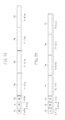
- FIGS. 7A , 7 B, 7 C, and 7 D each illustrate an example of a structure of a code indicating items for service maintenance provided to the image forming apparatus according to the first exemplary embodiment.
- FIG. 8 illustrates an example of a correspondence table between items for service maintenance and code numbers assigned to the items.
- FIG. 9 illustrates an example of a structure of a code indicating items for service maintenance provided to the image forming apparatus according to a second exemplary embodiment.
- FIG. 10 is a flowchart illustrating an example of processing for the image forming apparatus according to the second exemplary embodiment to display an item screen for a maintenance mode based on an input code.
- FIG. 1 is a block diagram illustrating an example of a configuration of an image forming apparatus according to the first exemplary embodiment.
- a control block 100 in an image forming apparatus 110 controls the entire image forming apparatus 110 .
- a central processing unit (CPU) 1 reads out and executes a program, which has been computer-readably recorded on a program read-only memory (ROM) 3 , and controls each of the devices in the image forming apparatus 110 via a system bus 4 .
- CPU central processing unit
- ROM program read-only memory
- the CPU 1 a random access memory (RAM) 2 , the program ROM 3 , a network interface (I/F) 5 , a scanning unit I/F 6 , a printing unit I/F 7 , an external memory I/F 8 , an operation unit 9 , a counter 14 , a sensor 15 , and others are connected to the system bus 4 .
- the program ROM 3 stores various types of data in addition to the program to be executed by the CPU 1 .
- the RAM 2 is used as a work area of the CPU 1 .
- the network I/F 5 is an interface for connection to an external network environment 10 , such as Ethernet.
- the scanning unit I/F 6 communicates with a scanning unit 11 .
- the printing unit I/F 7 communicates with a printing unit (a printer engine) 12 that performs printing.
- the external memory I/F 8 is an interface for connection to an external memory 13 such as a universal serial bus (USB) flash drive.
- the operation unit 9 has a function of displaying various types of information and accepting input from a user.
- the sensor 15 includes a plurality of sensors, and detects various states of the image forming apparatus 110 .
- the counter 14 stores the number of times of various operations.
- the CPU 1 outputs an image signal serving as output information to the printing unit (the printer engine) 12 via the printing unit I/F 7 based on the control program stored in the program ROM 3 .
- the CPU 1 similarly receives an image signal from the scanning unit 11 via the scanning unit I/F 6 .
- the CPU 1 receives sensor information from various sensors 15 under controller management.
- the CPU 1 performs control to manage and store a value counted up by measuring the number of times of operations in the counter 14 .
- the scanning unit 11 and the printing unit 12 respectively store the sensor information and the counter 14 , which is not illustrated, and the CPU 1 can acquire their respective values via the scanning unit I/F 6 and the printing unit I/F 7 .
- FIG. 2 illustrates the operation unit 9 in the image forming apparatus 110 illustrated in FIG. 1 .
- the operation unit 9 includes a display unit 20 with a touch panel, various types of control keys (collectively referred to as a control key 21 ) including a numeric keypad, and special keys (collectively referred to as a special key 22 ) for switching a content to be displayed on the display unit 20 .
- the display in the present exemplary embodiment, described below, is performed on the display unit 20 , and input to the display is executed with a touch on the display unit 20 or the control key 21 .
- An interface for service maintenance will be described below with reference to FIGS. 3A and 3B and FIG. 4 .
- the content to be displayed on the display unit 20 in the operation unit 9 is changed for each function used by the image forming apparatus 110 .
- FIGS. 3A and 3B illustrate examples of display on a screen for normal service maintenance used by a maintenance engineer.
- the screen for normal service maintenance is not opened to a customer user, and can be used only by the maintenance engineer.
- the screen for normal service maintenance has conventionally been provided in the image forming apparatus 110 .
- FIG. 4 illustrates an example of a tree structure of a menu including items for service maintenance.
- the items for service maintenance are positioned in a final node of the menu having the tree structure (the display level>the second layer>the third layer>the fourth layer>the items in the example illustrated in FIG. 4 ).
- the items for service maintenance settings of version information, various types of sensor information, counter information, and an adjustment value, and a state of a switch for an operation change can be displayed, and their setting values can be changed.
- the highest layer (a first layer) is classified as the “display level”.
- the display level indicates the levels of layers and items below the first layer in the tree structure.
- the levels include a level used only for confirmation during normal maintenance work, a level used when setting is changed during normal maintenance work, and a level used only in a significantly special case.
- the second layer is classified by parts (the controller block 100 , the printing unit 12 , the scanning unit 11 , and a feeder, etc.) of the image forming apparatus 110 .
- the third layer is classified by functions of the parts in the second layer.
- the third layer below the second layer (the printing unit 12 ) is classified by a function of switching operation modes, an adjusting function, and component levels (a fixing unit, a feeding unit, and an image forming unit) in the part.
- the fourth layer changes depending on the meaning of the third layer above the fourth layer.
- the layer below the fourth layer is the final layer in the tree structure, and indicates individual items.
- FIG. 3A illustrates an example of display in a halfway stage before the tree is followed up to the item.
- “LEVEL 2 ” ( 31 ), “FEEDER” ( 32 ), and “OPTION” ( 33 ) are respectively selected in the display level, the second layer, and the third layer.
- the selected layers are displayed as “LEVEL 2 >FEEDER>OPTION”.
- node names SENSOR, MENU 1 , MENU 3 , MENU 4 , and MENU 5
- a node (“OPTION” ( 33 ) illustrated in FIG. 4 ) (LEVEL 2 >FEEDER>OPTION) are displayed as the menu in the display area 38 .
- FIG. 3B illustrates display when the maintenance engineer selects the “SENSOR” ( 34 ) as the menu in FIG. 3A to have reached the final layer.
- the final node indicates items. Therefore, a value managed by each of the items is displayed.
- the number of items that can be displayed is limited by the limitation of the screen size of the display unit 20 . Therefore, a maximum of eight items are simultaneously displayed. However, items to be respectively displayed using a left button ( 35 ) and a right button ( 36 ) can be switched, i.e., scrolled.
- the items that can be simultaneously displayed are only items that are included in the same final node and within the same scroll range.
- the maintenance engineer at the site examines the manual and the website, to obtain information about the coping method. For example, a database of cases indicating the coping method is operated in the website, so that the maintenance engineer can input and examine the case required to be adjusted.
- the coping method includes a method for checking the current state of an image forming apparatus based on a sensor value to change an adjustment value according to the sensor value. More specifically, a voltage value of a specific component or a table of a potential map for each temperature is changed based on a temperature and a humidity inside the image forming apparatus. In the manual and the website, an instruction to confirm the items and change their setting is placed.
- FIG. 5 illustrates an example of display of a screen for service maintenance according to the present exemplary embodiment.
- FIG. 5 illustrates an example in which items for performing information display and adjustment value setting required to cope with a specific malfunction respectively belong to entirely different nodes in the tree structure.
- information display and adjustment value setting may be required for an item “SENSOR_ 1 ” belonging to the display level “2”>the second layer “FEEDER”>the third layer “OPTION”>the fourth layer “SENSOR”, an item.
- TPTBL 1 belonging to the display level “1”>the second layer “COPIER”>the third layer “ADJUST”>the fourth layer “OPTION”
- information display and adjustment value setting for the four items respectively belonging to the entirely different nodes in the tree structure may be required to cope with a specific malfunction.
- interfaces for service maintenance as illustrated in FIGS. 3A and 3B the user needs to frequency access required items by following the menu having the tree structure for each of the required items, which is significantly inconvenient because it takes a lot of time and labor to perform an operation, and work for comparing displayed values cannot be performed.
- interfaces for performing information display and adjustment value setting for a plurality of items required to cope with the above-described malfunction can be displayed on the same screen, therefore, the above-described problem can be solved.
- an interface as illustrated in FIG. 5 is used, so that values of a plurality of items required to cope with the malfunction may be compared and confirmed, like in information 53 a to 53 d , to be set.
- a serviceman may select the item to be adjusted by touching one of information 54 b to 54 d , and can set the item to be adjusted by inputting an adjustment value for the item from the control key 21 .
- Cases required to be adjusted in a general image forming apparatus and items required to be adjusted, which have occurred in a past model and a model of the same group, may be previously stocked.
- a program for service maintenance is upgraded, so that content thereof may also be updated.
- the program for service maintenance may be upgraded using the same means as a mechanism for upgrading the program for the image forming apparatus because the program for service maintenance is included in the program for the image forming apparatus.
- the means includes a method for downloading the program using a dedicated tool by connecting the image forming apparatus and a personal computer in a peer-to-peer fashion, a method for downloading the program from a download site via a network by the image forming apparatus, and a method for downloading the program using an external memory such as a USB flash drive.
- Display of a screen having measures accumulated therein can desirably be performed without changing the program in a new combination. Therefore, a development company places a code including 8 to 16 digit sequences described below, when a new case required to be adjusted and measures therefor are added to an addendum of the manual and the website as information about measures.
- the maintenance engineer searches the addendum of the manual and the website for the case required to be adjusted to acquire the placed code together with information about coping means.
- a function of enabling input of code information to a service maintenance screen of the image forming apparatus 110 (a code input portion 51 illustrated in FIG. 5 ) is prepared, and the CPU 1 accepts code input from the maintenance engineer via the operation unit 9 . If inputting the code information, the serviceman selects the code by touching the code input portion 51 , and inputs the code from the numeric keypad of the control key 21 .
- the image forming apparatus 110 extracts data indicating items for measures from the code input from the code input portion 51 , reconstructs the required items, and displays the reconstructed items on the service maintenance screen ( FIG. 5 ).
- the CPU 1 specifies, out of all the maintenance items, the plurality of maintenance items to be displayed by the image forming apparatus 110 based on the code information input from the operation unit 9 , generates a screen for displaying the specified plurality of maintenance items on the same screen, and displays the generated screen 50 illustrated in FIG. 5 .
- FIGS. 7A , 7 B, 7 C, and 7 D illustrate respective examples of a structure of a code indicating items for service maintenance provided in the image forming apparatus 110 according to the first exemplary embodiment.
- two bits at the head of the code correspond to a format bit 71 indicating each of four types of formats.
- the subsequent two bits correspond to a data number bit 72 indicating the number of data portions to be designated in the code. Further, the subsequent two bits correspond to a checksum bit 73 .
- the checksum bit 73 includes determination information for determining whether the code is effective by determining the presence or absence of an error in the code.
- the subsequent data portions 74 to 77 differ in bit lengths depending on the format bit 71 .
- the respective data portions 74 to 77 store code numbers assigned to the items for service maintenance, as illustrated in a table in FIG. 8 .
- the number of data portions is not limited to four. More specifically, a code to be input to the code input portion 51 to cope with a specific malfunction includes one or more code numbers assigned to the items for service maintenance provided in the image forming apparatus 110 .
- FIG. 8 illustrates an example of a correspondence table of items for service maintenance and code numbers assigned to the items. More specifically, FIG. 8 illustrates correspondence information between code numbers stored in the respective data portions 74 to 77 illustrated in FIGS. 7A , 7 B, 7 C, and 7 D and the items for service maintenance. Data corresponding to the correspondence table illustrated in FIG. 8 is stored in the program ROM 3 in the image forming apparatus 110 .
- all the data portions 74 , 75 , 76 , and 77 may be eight bits in length, as illustrated in FIG. 7A , so that the entire bit size of the code may be reduced.
- the items are assigned in use frequency order in a step-by-step manner.
- a code is generated, a format is determined to match the item assigned the maximum number of bits out of the plurality of items included in the code. If only items having high frequencies of use are included in the code, therefore, the number of digits of the code may fall within 11 or less.
- the number of digits of the code is not limited to 11 or less, and can be changed in design depending on the number of items for service maintenance provided in the image forming apparatus 110 .
- FIG. 6 is a flowchart illustrating an example of processing for the image forming apparatus 110 to display an item screen for a maintenance mode based on the input code.
- Each of steps in the flowchart is implemented when the CPU 1 in the image forming apparatus 110 reads out and executes a program that is computer-readably recorded in the program ROM 3 .
- step S 601 when the maintenance engineer touches the code input portion 51 , the CPU 1 first accepts input of a code from a numeric keypad of the control key 21 . Then, when the maintenance engineer inputs the code with the numeric keypad, the CPU 1 detects the input to acquire the code input from the numeric keypad.
- the code includes a decimal number that can be input from the numeric keypad.
- the code is not limited to only a number.
- a character string which can be input using a soft keyboard and a USB-connected hard keyboard, may also be used.
- step S 602 the CPU 1 acquires the format bit 71 from the code that has been acquired in step S 601 .
- step S 603 the CPU 1 acquires the checksum bit 73 from the code that has been acquired in step S 601 , and determines whether a checksum of the numbers of bits assigned to the respective data portions 74 to 77 is correct.
- the checksum is adjusted so that ones digit is even when the code excluding the format bit 71 and the data number bit 72 is indicated in bit notation, for example, to check whether the code has been input in error.
- the checksum may be adjusted so that ones digit is even when the input code is directly indicated in bit notation, to check whether the code has been input in error.
- step S 603 If it is determined that the checksum is not correct (NO in step S 603 ), the CPU 1 determines that the code, which has been acquired in step S 601 , is not effective but is in error (NG), and the processing proceeds to step S 608 .
- step S 608 the CPU 1 displays error information (error information indicating that there is an error in the input code) on the display unit 20 in the operation unit 9 , and the processing proceeds to step S 601 .
- step S 601 the CPU 1 waits until a code is input again.
- step S 603 if it is determined that the checksum is correct (YES in step S 603 ), the CPU 1 determines that the code, which has been acquired in step S 601 , is effective (OK). Then, the processing proceeds to step S 604 .
- step S 604 the CPU 1 acquires the number of data from the data number bit 72 in the code that has been acquired in step S 601 , and extracts code numbers corresponding to the number of data from the data portion 74 to the data portion 77 in the code.
- the data portions 74 to 77 differ in bit size depending on the format bit 71 , so that the code numbers assigned to the items corresponding to the number of data indicated by the data number bit 72 can be extracted from the data portions 74 to 77 in the bit size.
- step S 605 the CPU 1 extracts each of the items from the code numbers assigned to the items that have been extracted in step S 604 using the code table ( FIG. 8 ) stored in the program ROM 3 .
- step S 606 the CPU 1 determines whether all the items corresponding to the code numbers have been extracted (have been included in the code table) in the extraction processing of step S 605 . If the CPU 1 determines that the item corresponding to one of the code numbers has not been extracted from the code table (has not been included in the code table) in the extraction processing of step S 605 (NO in step S 606 ), the processing proceeds to step S 608 .
- step S 608 the CPU 1 displays error information on the display unit 20 in the operation unit 9 , and the processing proceeds to step S 601 .
- step S 601 the CPU 1 performs control to wait until a code is input again.
- step S 605 determines that all the items corresponding to the code numbers have been extracted from the code table (have been included in the code table) in the extraction processing in step S 605 (YES in step S 606 ).
- the processing proceeds to step S 607 .
- step S 607 the CPU 1 performs control to dynamically generate and display the screen 50 for displaying information about the items (e.g., the information 53 a to 53 d illustrated in FIG. 5 ) extracted from the code table in step S 605 .
- the CPU 1 then performs control to accept setting of an adjustment value for each of the displayed items from the screen 50 .
- the CPU 1 performs control to accept input of the adjustment value for the item from the control key 21 .
- the CPU 1 performs control to set the input adjustment value to the item.
- the interface having items required to cope with the newest case collected therein may be dynamically constructed and provided even for the plurality of items that have been distributed in a deep layer structure.
- man-hours required for the serviceman to access the required items may be significantly reduced.
- an interface, on which the newest information has been reflected may be provided by only inputting a simple code, like in the code input portion 51 illustrated in FIG. 5 , without installing a new program on the image forming apparatus 110 or updating the current program.
- the service maintenance can be done without depending on the environment (e.g., the network policy) at an installation destination of the image forming apparatus 110 .
- the interface for accessing each of the items for service maintenance which have been conventionally provided, as illustrated in FIGS. 3A and 3B , is categorized by each feature of the item, and is not suitable for efficient work because the items required to cope with the case are scattered.
- the program for the image forming apparatus 110 may be corrected and coped with by providing a dedicated screen. To reflect the newest maintenance information, however, the image forming apparatus 110 may be difficult in operation to update the program every time the maintenance information is reflected.
- the screen having items required to cope with the newest case collected therein e.g., the screen 50 illustrated in FIG. 5
- the screen 50 illustrated in FIG. 5 may be dynamically generated and provided by code input (e.g., the code input portion 51 illustrated in FIG. 5 ) without updating the program for the image forming apparatus 110 . Therefore, the above-described problem may be solved.
- a second exemplary embodiment will be described below.
- a configuration in which a code includes information about an item included in the code and checksum information for ensuring the certainty of a code number has been described.
- additional information for confirming whether an image forming apparatus to which a code has been input is a target model of the code is added to the code as determination information for determining whether the code is effective.
- FIG. 9 illustrates an example of a structure of a code indicating items for service maintenance provided to the image forming apparatus 110 according to the second exemplary embodiment.
- OPTION FLAG 91
- OPTION DATA 92
- a model code may be included as the option to prevent the method from being misused in a model other than the target model.
- OPTION FLAG ( 91 ) indicates a model code (model information) of the image forming apparatus 110 . If OPTION FLAG ( 91 ) is “01”, OPTION DATA ( 92 ) indicates the serial number of the image forming apparatus 110 . If OPTION FLAG ( 91 ) is “10”, OPTION DATA ( 92 ) indicates date-and-time information about an expiration date of the code.
- FIG. 10 is a flowchart illustrating an example of processing for an image forming apparatus 110 according to the second exemplary embodiment to display an item screen for a maintenance mode based on an input code.
- Each of the steps in the flowchart is implemented when the CPU 1 in the image forming apparatus 110 reads out and executes a program that is computer-readably recorded in the program ROM 3 .
- Steps S 901 to S 906 illustrated in FIG. 10 are the same as steps S 601 to S 606 illustrated in FIG. 6 in the first exemplary embodiment, and hence description thereof is not repeated.
- the CPU 1 acquires OPTION FLAG ( 91 ) and OPTION DATA ( 92 ) from the code that has been acquired in step S 901 .
- the CPU 1 determines whether an option is effective. If OPTION FLAG ( 91 ) is “00”, a value of OPTION DATA ( 92 ) indicates a model code of the image forming apparatus 110 .
- the CPU 1 determines whether the option is effective depending on whether the value of OPTION DATA ( 92 ) matches the model code of the image forming apparatus 110 .
- the model code (the model information) of the image forming apparatus 110 is stored in a model information storage unit (a storage area in the program ROM 3 ).
- step S 910 the CPU 1 displays an error information on the display unit 20 in the operation unit 9 , and the processing proceeds to step S 901 .
- step S 901 the CPU 1 performs control to wait until a code is input.
- step S 908 the CPU 1 determines that the option is effective (i.e., the acquired code is effective) (YES in step S 908 ), and the processing proceeds to step S 909 .
- step S 909 the CPU 1 performs control to display each of the items, which have been extracted from a code table in step S 905 , on the screen 50 .
- the CPU 1 then performs control to accept setting of an adjustment value for each of the displayed items on the screen 50 .
- step S 901 determines that the option is ineffective (i.e., the acquired code is ineffective) (NO in step S 908 ), and the processing proceeds to step S 910 .
- the serial number of the image forming apparatus 110 is stored in a serial number storage unit (the storage area in the program ROM 3 ).
- step S 901 If the expiration date included in the code, which has been input in step S 901 , exceeds the date at the time point where the code has been input, the option is ineffective (i.e., the acquired code is ineffective) (NO in step S 908 ), and the processing proceeds to step S 910 .
- the input code can be checked whether the input code is ineffective by including, in the code, information (OPTION FLAG ( 91 ) and OPTION DATA ( 92 )) such as the type and serial number of the image forming apparatus to which the code corresponds, and an expiration date of the code.
- information OPTION FLAG ( 91 ) and OPTION DATA ( 92 )
- the configuration in which a code is input is not limited to this.
- information e.g., a barcode placed in a service manual or a website may be read out by the scanning unit 11 , to extract a code.
- aspects of the present invention can also be realized by a computer of a system or apparatus (or devices such as a CPU or MPU) that reads out and executes a program recorded on a memory device to perform the functions of the above-described embodiment (s), and by a method, the steps of which are performed by a computer of a system or apparatus by, for example, reading out and executing a program recorded on a memory device to perform the functions of the above-described embodiment (s).
- the program is provided to the computer for example via a network or from a recording medium of various types serving as the memory device (e.g., computer-readable medium).
Landscapes
- Engineering & Computer Science (AREA)
- Human Computer Interaction (AREA)
- Multimedia (AREA)
- Signal Processing (AREA)
- Control Or Security For Electrophotography (AREA)
- Facsimiles In General (AREA)
- Accessory Devices And Overall Control Thereof (AREA)
Applications Claiming Priority (2)
| Application Number | Priority Date | Filing Date | Title |
|---|---|---|---|
| JP2012019897A JP5924960B2 (ja) | 2012-02-01 | 2012-02-01 | 画像形成装置、画像形成装置の制御方法、及びプログラム |
| JP2012-019897 | 2012-02-01 |
Publications (2)
| Publication Number | Publication Date |
|---|---|
| US20130194629A1 US20130194629A1 (en) | 2013-08-01 |
| US9025183B2 true US9025183B2 (en) | 2015-05-05 |
Family
ID=48869972
Family Applications (1)
| Application Number | Title | Priority Date | Filing Date |
|---|---|---|---|
| US13/748,348 Expired - Fee Related US9025183B2 (en) | 2012-02-01 | 2013-01-23 | Image forming apparatus, method for controlling image forming apparatus, and storage medium for performing maintenance on an image forming apparatus |
Country Status (2)
| Country | Link |
|---|---|
| US (1) | US9025183B2 (enExample) |
| JP (1) | JP5924960B2 (enExample) |
Families Citing this family (3)
| Publication number | Priority date | Publication date | Assignee | Title |
|---|---|---|---|---|
| JP6859833B2 (ja) * | 2017-04-27 | 2021-04-14 | 富士電機株式会社 | 設備管理装置、設備管理システム、プログラムおよび設備管理方法 |
| WO2018042940A1 (ja) * | 2016-09-01 | 2018-03-08 | 富士電機株式会社 | 設備管理装置、設備管理システム、プログラムおよび設備管理方法 |
| US11295370B1 (en) * | 2017-05-26 | 2022-04-05 | Amazon Technologies, Inc. | Buyback offers using precalculated cached user data |
Citations (2)
| Publication number | Priority date | Publication date | Assignee | Title |
|---|---|---|---|---|
| JP2003114779A (ja) | 2001-10-04 | 2003-04-18 | Ricoh Co Ltd | 画像形成装置の設定処理装置 |
| US20040046984A1 (en) * | 2002-04-19 | 2004-03-11 | Seiko Epson Corporation | Printer, an operation panel thereof having a function for doing maintenance of print station |
Family Cites Families (1)
| Publication number | Priority date | Publication date | Assignee | Title |
|---|---|---|---|---|
| JPS617906A (ja) * | 1984-06-22 | 1986-01-14 | Ricoh Co Ltd | 装置状態の表示装置 |
-
2012
- 2012-02-01 JP JP2012019897A patent/JP5924960B2/ja not_active Expired - Fee Related
-
2013
- 2013-01-23 US US13/748,348 patent/US9025183B2/en not_active Expired - Fee Related
Patent Citations (2)
| Publication number | Priority date | Publication date | Assignee | Title |
|---|---|---|---|---|
| JP2003114779A (ja) | 2001-10-04 | 2003-04-18 | Ricoh Co Ltd | 画像形成装置の設定処理装置 |
| US20040046984A1 (en) * | 2002-04-19 | 2004-03-11 | Seiko Epson Corporation | Printer, an operation panel thereof having a function for doing maintenance of print station |
Also Published As
| Publication number | Publication date |
|---|---|
| JP5924960B2 (ja) | 2016-05-25 |
| US20130194629A1 (en) | 2013-08-01 |
| JP2013158917A (ja) | 2013-08-19 |
Similar Documents
| Publication | Publication Date | Title |
|---|---|---|
| US8984413B2 (en) | Transmission system, transmission apparatus, and method | |
| US10567435B2 (en) | Apparatus that is managed in accordance with a security policy, control method thereof, and storage medium | |
| US9411450B2 (en) | Display input device, image forming apparatus, and control method of display input device | |
| JP5102650B2 (ja) | 情報検索システム、情報検索方法、情報検索プログラム及び記録媒体 | |
| US20100245897A1 (en) | Electronic apparatus and image forming system | |
| US9025183B2 (en) | Image forming apparatus, method for controlling image forming apparatus, and storage medium for performing maintenance on an image forming apparatus | |
| JP2010218062A (ja) | 情報提供装置、情報提供システム、情報提供方法、情報提供プログラム、及びそのプログラムを記録した記録媒体 | |
| US6427053B1 (en) | Method and apparatus for monitoring parameters corresponding to operation of an electrophotographic marking machine | |
| US10204232B2 (en) | Apparatus capable of executing adjusting operation, control method for controlling adjusting operation of apparatus, and storage medium | |
| JP5109508B2 (ja) | ユーザインターフェイス装置およびプログラム | |
| US20100195145A1 (en) | Image processing apparatus, control method for image processing apparatus, and storage medium storing control program therefor | |
| JP2019161269A (ja) | 情報処理装置及びプログラム | |
| JP6291987B2 (ja) | 処理装置、画像形成装置、検索方法、および検索プログラム | |
| JP2018028832A (ja) | 認証装置 | |
| KR20080060905A (ko) | 시스템 진단을 수행하는 화상형성장치 및 그 방법 | |
| JP2019186599A (ja) | 画像形成装置及びプログラム | |
| JP5299898B2 (ja) | データベース生成装置、データベース生成方法及びコンピュータプログラム | |
| JP2010152601A (ja) | プリンタードライバー | |
| JP5402044B2 (ja) | 保守制御装置、保守制御システム及び保守制御プログラム | |
| US9507573B2 (en) | Driver program generating apparatus, driver program generating method, driver program generating program, and driver program | |
| JP6274463B2 (ja) | 機器管理方法 | |
| JP2014132492A (ja) | 情報提供装置、情報提供システム、情報提供方法、情報提供プログラム、及びそのプログラムを記録した記録媒体 | |
| JP6323371B2 (ja) | 情報処理装置、情報処理方法 | |
| JP2019080097A (ja) | シミュレート装置、画像形成装置、装置設定方法および装置設定プログラム | |
| JP2025102518A (ja) | 情報装置、情報処理方法、及び情報処理プログラム |
Legal Events
| Date | Code | Title | Description |
|---|---|---|---|
| AS | Assignment |
Owner name: CANON KABUSHIKI KAISHA, JAPAN Free format text: ASSIGNMENT OF ASSIGNORS INTEREST;ASSIGNOR:KOJIMA, NOBUYUKI;REEL/FRAME:030330/0846 Effective date: 20130117 |
|
| STCF | Information on status: patent grant |
Free format text: PATENTED CASE |
|
| FEPP | Fee payment procedure |
Free format text: MAINTENANCE FEE REMINDER MAILED (ORIGINAL EVENT CODE: REM.); ENTITY STATUS OF PATENT OWNER: LARGE ENTITY |
|
| LAPS | Lapse for failure to pay maintenance fees |
Free format text: PATENT EXPIRED FOR FAILURE TO PAY MAINTENANCE FEES (ORIGINAL EVENT CODE: EXP.); ENTITY STATUS OF PATENT OWNER: LARGE ENTITY |
|
| STCH | Information on status: patent discontinuation |
Free format text: PATENT EXPIRED DUE TO NONPAYMENT OF MAINTENANCE FEES UNDER 37 CFR 1.362 |
|
| FP | Expired due to failure to pay maintenance fee |
Effective date: 20190505 |