US9017600B2 - Methods of forming molybdenum sputtering targets - Google Patents
Methods of forming molybdenum sputtering targets Download PDFInfo
- Publication number
- US9017600B2 US9017600B2 US13/849,918 US201313849918A US9017600B2 US 9017600 B2 US9017600 B2 US 9017600B2 US 201313849918 A US201313849918 A US 201313849918A US 9017600 B2 US9017600 B2 US 9017600B2
- Authority
- US
- United States
- Prior art keywords
- billet
- cases
- powder
- worked
- temperature
- Prior art date
- Legal status (The legal status is an assumption and is not a legal conclusion. Google has not performed a legal analysis and makes no representation as to the accuracy of the status listed.)
- Expired - Fee Related, expires
Links
Images


Classifications
-
- C—CHEMISTRY; METALLURGY
- C23—COATING METALLIC MATERIAL; COATING MATERIAL WITH METALLIC MATERIAL; CHEMICAL SURFACE TREATMENT; DIFFUSION TREATMENT OF METALLIC MATERIAL; COATING BY VACUUM EVAPORATION, BY SPUTTERING, BY ION IMPLANTATION OR BY CHEMICAL VAPOUR DEPOSITION, IN GENERAL; INHIBITING CORROSION OF METALLIC MATERIAL OR INCRUSTATION IN GENERAL
- C23C—COATING METALLIC MATERIAL; COATING MATERIAL WITH METALLIC MATERIAL; SURFACE TREATMENT OF METALLIC MATERIAL BY DIFFUSION INTO THE SURFACE, BY CHEMICAL CONVERSION OR SUBSTITUTION; COATING BY VACUUM EVAPORATION, BY SPUTTERING, BY ION IMPLANTATION OR BY CHEMICAL VAPOUR DEPOSITION, IN GENERAL
- C23C14/00—Coating by vacuum evaporation, by sputtering or by ion implantation of the coating forming material
- C23C14/22—Coating by vacuum evaporation, by sputtering or by ion implantation of the coating forming material characterised by the process of coating
- C23C14/34—Sputtering
- C23C14/3407—Cathode assembly for sputtering apparatus, e.g. Target
- C23C14/3414—Metallurgical or chemical aspects of target preparation, e.g. casting, powder metallurgy
-
- B—PERFORMING OPERATIONS; TRANSPORTING
- B22—CASTING; POWDER METALLURGY
- B22F—WORKING METALLIC POWDER; MANUFACTURE OF ARTICLES FROM METALLIC POWDER; MAKING METALLIC POWDER; APPARATUS OR DEVICES SPECIALLY ADAPTED FOR METALLIC POWDER
- B22F1/00—Metallic powder; Treatment of metallic powder, e.g. to facilitate working or to improve properties
-
- B—PERFORMING OPERATIONS; TRANSPORTING
- B22—CASTING; POWDER METALLURGY
- B22F—WORKING METALLIC POWDER; MANUFACTURE OF ARTICLES FROM METALLIC POWDER; MAKING METALLIC POWDER; APPARATUS OR DEVICES SPECIALLY ADAPTED FOR METALLIC POWDER
- B22F3/00—Manufacture of workpieces or articles from metallic powder characterised by the manner of compacting or sintering; Apparatus specially adapted therefor ; Presses and furnaces
- B22F3/02—Compacting only
- B22F3/04—Compacting only by applying fluid pressure, e.g. by cold isostatic pressing [CIP]
-
- B—PERFORMING OPERATIONS; TRANSPORTING
- B22—CASTING; POWDER METALLURGY
- B22F—WORKING METALLIC POWDER; MANUFACTURE OF ARTICLES FROM METALLIC POWDER; MAKING METALLIC POWDER; APPARATUS OR DEVICES SPECIALLY ADAPTED FOR METALLIC POWDER
- B22F3/00—Manufacture of workpieces or articles from metallic powder characterised by the manner of compacting or sintering; Apparatus specially adapted therefor ; Presses and furnaces
- B22F3/10—Sintering only
-
- B—PERFORMING OPERATIONS; TRANSPORTING
- B22—CASTING; POWDER METALLURGY
- B22F—WORKING METALLIC POWDER; MANUFACTURE OF ARTICLES FROM METALLIC POWDER; MAKING METALLIC POWDER; APPARATUS OR DEVICES SPECIALLY ADAPTED FOR METALLIC POWDER
- B22F3/00—Manufacture of workpieces or articles from metallic powder characterised by the manner of compacting or sintering; Apparatus specially adapted therefor ; Presses and furnaces
- B22F3/12—Both compacting and sintering
- B22F3/16—Both compacting and sintering in successive or repeated steps
- B22F3/162—Machining, working after consolidation
-
- B—PERFORMING OPERATIONS; TRANSPORTING
- B22—CASTING; POWDER METALLURGY
- B22F—WORKING METALLIC POWDER; MANUFACTURE OF ARTICLES FROM METALLIC POWDER; MAKING METALLIC POWDER; APPARATUS OR DEVICES SPECIALLY ADAPTED FOR METALLIC POWDER
- B22F3/00—Manufacture of workpieces or articles from metallic powder characterised by the manner of compacting or sintering; Apparatus specially adapted therefor ; Presses and furnaces
- B22F3/17—Manufacture of workpieces or articles from metallic powder characterised by the manner of compacting or sintering; Apparatus specially adapted therefor ; Presses and furnaces by forging
- B22F3/172—Continuous compaction, e.g. rotary hammering
-
- B—PERFORMING OPERATIONS; TRANSPORTING
- B22—CASTING; POWDER METALLURGY
- B22F—WORKING METALLIC POWDER; MANUFACTURE OF ARTICLES FROM METALLIC POWDER; MAKING METALLIC POWDER; APPARATUS OR DEVICES SPECIALLY ADAPTED FOR METALLIC POWDER
- B22F3/00—Manufacture of workpieces or articles from metallic powder characterised by the manner of compacting or sintering; Apparatus specially adapted therefor ; Presses and furnaces
- B22F3/20—Manufacture of workpieces or articles from metallic powder characterised by the manner of compacting or sintering; Apparatus specially adapted therefor ; Presses and furnaces by extruding
-
- B—PERFORMING OPERATIONS; TRANSPORTING
- B22—CASTING; POWDER METALLURGY
- B22F—WORKING METALLIC POWDER; MANUFACTURE OF ARTICLES FROM METALLIC POWDER; MAKING METALLIC POWDER; APPARATUS OR DEVICES SPECIALLY ADAPTED FOR METALLIC POWDER
- B22F3/00—Manufacture of workpieces or articles from metallic powder characterised by the manner of compacting or sintering; Apparatus specially adapted therefor ; Presses and furnaces
- B22F3/24—After-treatment of workpieces or articles
-
- B—PERFORMING OPERATIONS; TRANSPORTING
- B22—CASTING; POWDER METALLURGY
- B22F—WORKING METALLIC POWDER; MANUFACTURE OF ARTICLES FROM METALLIC POWDER; MAKING METALLIC POWDER; APPARATUS OR DEVICES SPECIALLY ADAPTED FOR METALLIC POWDER
- B22F5/00—Manufacture of workpieces or articles from metallic powder characterised by the special shape of the product
- B22F5/006—Manufacture of workpieces or articles from metallic powder characterised by the special shape of the product of flat products, e.g. sheets
-
- C—CHEMISTRY; METALLURGY
- C21—METALLURGY OF IRON
- C21D—MODIFYING THE PHYSICAL STRUCTURE OF FERROUS METALS; GENERAL DEVICES FOR HEAT TREATMENT OF FERROUS OR NON-FERROUS METALS OR ALLOYS; MAKING METAL MALLEABLE, e.g. BY DECARBURISATION OR TEMPERING
- C21D8/00—Modifying the physical properties of ferrous metals or ferrous alloys by deformation combined with, or followed by, heat treatment
- C21D8/02—Modifying the physical properties of ferrous metals or ferrous alloys by deformation combined with, or followed by, heat treatment during manufacturing of plates or strips
- C21D8/0221—Modifying the physical properties of ferrous metals or ferrous alloys by deformation combined with, or followed by, heat treatment during manufacturing of plates or strips characterised by the working steps
-
- C—CHEMISTRY; METALLURGY
- C21—METALLURGY OF IRON
- C21D—MODIFYING THE PHYSICAL STRUCTURE OF FERROUS METALS; GENERAL DEVICES FOR HEAT TREATMENT OF FERROUS OR NON-FERROUS METALS OR ALLOYS; MAKING METAL MALLEABLE, e.g. BY DECARBURISATION OR TEMPERING
- C21D8/00—Modifying the physical properties of ferrous metals or ferrous alloys by deformation combined with, or followed by, heat treatment
- C21D8/02—Modifying the physical properties of ferrous metals or ferrous alloys by deformation combined with, or followed by, heat treatment during manufacturing of plates or strips
- C21D8/0247—Modifying the physical properties of ferrous metals or ferrous alloys by deformation combined with, or followed by, heat treatment during manufacturing of plates or strips characterised by the heat treatment
-
- C—CHEMISTRY; METALLURGY
- C22—METALLURGY; FERROUS OR NON-FERROUS ALLOYS; TREATMENT OF ALLOYS OR NON-FERROUS METALS
- C22C—ALLOYS
- C22C1/00—Making non-ferrous alloys
- C22C1/04—Making non-ferrous alloys by powder metallurgy
- C22C1/045—Alloys based on refractory metals
-
- C—CHEMISTRY; METALLURGY
- C22—METALLURGY; FERROUS OR NON-FERROUS ALLOYS; TREATMENT OF ALLOYS OR NON-FERROUS METALS
- C22C—ALLOYS
- C22C27/00—Alloys based on rhenium or a refractory metal not mentioned in groups C22C14/00 or C22C16/00
- C22C27/04—Alloys based on tungsten or molybdenum
-
- C—CHEMISTRY; METALLURGY
- C22—METALLURGY; FERROUS OR NON-FERROUS ALLOYS; TREATMENT OF ALLOYS OR NON-FERROUS METALS
- C22F—CHANGING THE PHYSICAL STRUCTURE OF NON-FERROUS METALS AND NON-FERROUS ALLOYS
- C22F1/00—Changing the physical structure of non-ferrous metals or alloys by heat treatment or by hot or cold working
- C22F1/16—Changing the physical structure of non-ferrous metals or alloys by heat treatment or by hot or cold working of other metals or alloys based thereon
- C22F1/18—High-melting or refractory metals or alloys based thereon
-
- C—CHEMISTRY; METALLURGY
- C23—COATING METALLIC MATERIAL; COATING MATERIAL WITH METALLIC MATERIAL; CHEMICAL SURFACE TREATMENT; DIFFUSION TREATMENT OF METALLIC MATERIAL; COATING BY VACUUM EVAPORATION, BY SPUTTERING, BY ION IMPLANTATION OR BY CHEMICAL VAPOUR DEPOSITION, IN GENERAL; INHIBITING CORROSION OF METALLIC MATERIAL OR INCRUSTATION IN GENERAL
- C23C—COATING METALLIC MATERIAL; COATING MATERIAL WITH METALLIC MATERIAL; SURFACE TREATMENT OF METALLIC MATERIAL BY DIFFUSION INTO THE SURFACE, BY CHEMICAL CONVERSION OR SUBSTITUTION; COATING BY VACUUM EVAPORATION, BY SPUTTERING, BY ION IMPLANTATION OR BY CHEMICAL VAPOUR DEPOSITION, IN GENERAL
- C23C14/00—Coating by vacuum evaporation, by sputtering or by ion implantation of the coating forming material
- C23C14/06—Coating by vacuum evaporation, by sputtering or by ion implantation of the coating forming material characterised by the coating material
- C23C14/14—Metallic material, boron or silicon
-
- C—CHEMISTRY; METALLURGY
- C23—COATING METALLIC MATERIAL; COATING MATERIAL WITH METALLIC MATERIAL; CHEMICAL SURFACE TREATMENT; DIFFUSION TREATMENT OF METALLIC MATERIAL; COATING BY VACUUM EVAPORATION, BY SPUTTERING, BY ION IMPLANTATION OR BY CHEMICAL VAPOUR DEPOSITION, IN GENERAL; INHIBITING CORROSION OF METALLIC MATERIAL OR INCRUSTATION IN GENERAL
- C23C—COATING METALLIC MATERIAL; COATING MATERIAL WITH METALLIC MATERIAL; SURFACE TREATMENT OF METALLIC MATERIAL BY DIFFUSION INTO THE SURFACE, BY CHEMICAL CONVERSION OR SUBSTITUTION; COATING BY VACUUM EVAPORATION, BY SPUTTERING, BY ION IMPLANTATION OR BY CHEMICAL VAPOUR DEPOSITION, IN GENERAL
- C23C14/00—Coating by vacuum evaporation, by sputtering or by ion implantation of the coating forming material
- C23C14/22—Coating by vacuum evaporation, by sputtering or by ion implantation of the coating forming material characterised by the process of coating
- C23C14/34—Sputtering
- C23C14/3471—Introduction of auxiliary energy into the plasma
- C23C14/3478—Introduction of auxiliary energy into the plasma using electrons, e.g. triode sputtering
-
- C—CHEMISTRY; METALLURGY
- C23—COATING METALLIC MATERIAL; COATING MATERIAL WITH METALLIC MATERIAL; CHEMICAL SURFACE TREATMENT; DIFFUSION TREATMENT OF METALLIC MATERIAL; COATING BY VACUUM EVAPORATION, BY SPUTTERING, BY ION IMPLANTATION OR BY CHEMICAL VAPOUR DEPOSITION, IN GENERAL; INHIBITING CORROSION OF METALLIC MATERIAL OR INCRUSTATION IN GENERAL
- C23C—COATING METALLIC MATERIAL; COATING MATERIAL WITH METALLIC MATERIAL; SURFACE TREATMENT OF METALLIC MATERIAL BY DIFFUSION INTO THE SURFACE, BY CHEMICAL CONVERSION OR SUBSTITUTION; COATING BY VACUUM EVAPORATION, BY SPUTTERING, BY ION IMPLANTATION OR BY CHEMICAL VAPOUR DEPOSITION, IN GENERAL
- C23C14/00—Coating by vacuum evaporation, by sputtering or by ion implantation of the coating forming material
- C23C14/22—Coating by vacuum evaporation, by sputtering or by ion implantation of the coating forming material characterised by the process of coating
- C23C14/34—Sputtering
- C23C14/3485—Sputtering using pulsed power to the target
-
- C—CHEMISTRY; METALLURGY
- C23—COATING METALLIC MATERIAL; COATING MATERIAL WITH METALLIC MATERIAL; CHEMICAL SURFACE TREATMENT; DIFFUSION TREATMENT OF METALLIC MATERIAL; COATING BY VACUUM EVAPORATION, BY SPUTTERING, BY ION IMPLANTATION OR BY CHEMICAL VAPOUR DEPOSITION, IN GENERAL; INHIBITING CORROSION OF METALLIC MATERIAL OR INCRUSTATION IN GENERAL
- C23C—COATING METALLIC MATERIAL; COATING MATERIAL WITH METALLIC MATERIAL; SURFACE TREATMENT OF METALLIC MATERIAL BY DIFFUSION INTO THE SURFACE, BY CHEMICAL CONVERSION OR SUBSTITUTION; COATING BY VACUUM EVAPORATION, BY SPUTTERING, BY ION IMPLANTATION OR BY CHEMICAL VAPOUR DEPOSITION, IN GENERAL
- C23C14/00—Coating by vacuum evaporation, by sputtering or by ion implantation of the coating forming material
- C23C14/22—Coating by vacuum evaporation, by sputtering or by ion implantation of the coating forming material characterised by the process of coating
- C23C14/34—Sputtering
- C23C14/35—Sputtering by application of a magnetic field, e.g. magnetron sputtering
-
- C—CHEMISTRY; METALLURGY
- C23—COATING METALLIC MATERIAL; COATING MATERIAL WITH METALLIC MATERIAL; CHEMICAL SURFACE TREATMENT; DIFFUSION TREATMENT OF METALLIC MATERIAL; COATING BY VACUUM EVAPORATION, BY SPUTTERING, BY ION IMPLANTATION OR BY CHEMICAL VAPOUR DEPOSITION, IN GENERAL; INHIBITING CORROSION OF METALLIC MATERIAL OR INCRUSTATION IN GENERAL
- C23C—COATING METALLIC MATERIAL; COATING MATERIAL WITH METALLIC MATERIAL; SURFACE TREATMENT OF METALLIC MATERIAL BY DIFFUSION INTO THE SURFACE, BY CHEMICAL CONVERSION OR SUBSTITUTION; COATING BY VACUUM EVAPORATION, BY SPUTTERING, BY ION IMPLANTATION OR BY CHEMICAL VAPOUR DEPOSITION, IN GENERAL
- C23C14/00—Coating by vacuum evaporation, by sputtering or by ion implantation of the coating forming material
- C23C14/22—Coating by vacuum evaporation, by sputtering or by ion implantation of the coating forming material characterised by the process of coating
- C23C14/34—Sputtering
- C23C14/46—Sputtering by ion beam produced by an external ion source
-
- B—PERFORMING OPERATIONS; TRANSPORTING
- B22—CASTING; POWDER METALLURGY
- B22F—WORKING METALLIC POWDER; MANUFACTURE OF ARTICLES FROM METALLIC POWDER; MAKING METALLIC POWDER; APPARATUS OR DEVICES SPECIALLY ADAPTED FOR METALLIC POWDER
- B22F3/00—Manufacture of workpieces or articles from metallic powder characterised by the manner of compacting or sintering; Apparatus specially adapted therefor ; Presses and furnaces
- B22F3/24—After-treatment of workpieces or articles
- B22F2003/248—Thermal after-treatment
-
- B—PERFORMING OPERATIONS; TRANSPORTING
- B22—CASTING; POWDER METALLURGY
- B22F—WORKING METALLIC POWDER; MANUFACTURE OF ARTICLES FROM METALLIC POWDER; MAKING METALLIC POWDER; APPARATUS OR DEVICES SPECIALLY ADAPTED FOR METALLIC POWDER
- B22F2301/00—Metallic composition of the powder or its coating
- B22F2301/20—Refractory metals
-
- B—PERFORMING OPERATIONS; TRANSPORTING
- B22—CASTING; POWDER METALLURGY
- B22F—WORKING METALLIC POWDER; MANUFACTURE OF ARTICLES FROM METALLIC POWDER; MAKING METALLIC POWDER; APPARATUS OR DEVICES SPECIALLY ADAPTED FOR METALLIC POWDER
- B22F2998/00—Supplementary information concerning processes or compositions relating to powder metallurgy
- B22F2998/10—Processes characterised by the sequence of their steps
Definitions
- the present invention relates to forms of molybdenum, their use as sputtering targets and method of their manufacture.
- the sputtering technique is a film-forming technique with which a plasma is utilized to generate ions striking a sputtering target so as to result in atoms of the sputtering target depositing on a substrate as a film.
- the sputtering technique is particularly used to produce a metallic layer in various manufacturing processes used in the semiconductor and the photoelectric industries.
- the properties of films formed during sputtering is related to the properties of the sputtering target itself, such as the size of the respective crystal grain and the formation of secondary phase with distribution characteristics.
- Various sputtering techniques are used in order to effect the deposition of a film over the surface of a substrate.
- Deposited metal films such as metal films on a flat panel display device, can be formed by a magnetron sputtering apparatus or other sputtering techniques.
- the magnetron sputtering apparatus induces plasma ions of a gas to bombard a target, causing surface atoms of the target material to be ejected therefrom and to be deposited as a film or layer on the surface of a substrate.
- a sputtering source in the form of a planar disc or rectangle is used as the target, and ejected atoms travel along a line-of-sight trajectory to deposit on top of a wafer whose deposition face is parallel to the erosion face of the target.
- a tubular-shaped sputtering target can also be used.
- the plasma is external and the atoms are sputtered from the exterior of the tube.
- the flat substrate is slowly passed over the target. Typically, its motion is horizontal, and in a direction at a right angle to the target axis, which is also horizontal. Thus the substrate can be gradually coated as it passes over the target.
- sputtering targets particularly those containing molybdenum
- These “non-uniformities” lead to non-uniform films being deposited onto substrates and devices, particularly flat panel displays that do not operate optimally.
- molybdenum-based sputtering targets are manufactured using a conventional thermomechanical working step.
- this methodology generally induces heterogeneity of grain size and texture.
- the heterogeneity in the sputtering targets typically leads to sputtered films that do not possess the uniformity desired in most semiconductor and photoelectric applications.
- large plates of pure molybdenum are required as sputtering targets.
- the production of large plates is accomplished through the machining and assembly of multiple plates, often referred to as segmented plates.
- the preparation of segmented plates requires an increased amount of machining and assembly cost compared to the production of a single plate ingot. Additionally, the assembly of different plates creates variability in the large segmented plate, which can cause unacceptable variability in films formed by sputtering the large plate target.
- the present invention is directed to molybdenum, sputtering targets characterized as having no or minimal texture banding or through thickness gradient.
- the present invention is additionally directed to a tubular-shaped sputtering target formed by:
- the present invention is also directed to a tubular-shaped sputtering target containing molybdenum having a uniform texture, which features particularly a 110 orientation parallel to the longitudinal direction and a 111 orientation relative to the radial direction.
- the present invention is additionally directed to a method of making a tubular sputtering target that includes:
- Embodiments of the invention are also directed to a disc-shaped sputtering target containing molybdenum having a uniform grain and texture.
- inventions of the invention are directed to large molybdenum plates having a non-segmented construction, weighing at least 300 kg, and containing at least 99% by weight of molybdenum.
- Additional embodiments of the invention are directed to a process for preparing the above-described plates, which includes the steps of:
- the present invention is further directed to sputtering targets and sintering tiles that include the above-described molybdenum plate.
- the present invention is additionally directed to a method of sputtering that includes subjecting any of the above-described sputtering targets to sputtering conditions and thereby sputtering the target.
- the present invention is further directed to a method of sputtering that includes subjecting the above-described sputtering target to sputtering conditions and thereby sputtering the target.
- the present invention is further directed to a method for making a thin film including the steps of:
- the present invention also provides a thin film made in accordance with the above-described method.
- the thin films can be used in electronic components such as semiconductor devices, thin film transistors, TFT-LCD devices, black matrix devices that enhance image contrast in Flat Panel Displays, solar cells, sensors, and gate device for CMOS (complementary metal oxide semiconductor) with tunable work functions.
- CMOS complementary metal oxide semiconductor
- FIG. 1 is a schematic view of a consolidated hollow billet according to the invention
- FIG. 2 is a schematic view of a hollow billet being extruded according to the present invention for extrusion of a tube;
- FIGS. 3A , 3 B and 3 C show electron backscatter diffraction (EBSD) electron micrographs relative to the longitudinal (z), radial (ND) and tangential (x) directions, respectively, of a tubular sputtering target according to the present invention
- FIG. 4 shows the EBSD micrograph of 3 B under higher magnification
- FIG. 5 shows the EBSD Pole Figure analysis of a tubular sputtering target according to the present invention
- FIG. 6 shows the EBSD Inverse Pole Figure analysis of a tubular sputtering target according to the present invention
- FIG. 7 is a schematic showing a solid billet being extruded according to the invention for intermediate work pieces
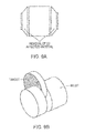
- FIGS. 8A and 8B show schematic views of upset forging a billet according to the present invention
- FIGS. 9A and 9B show sputtering target plates according to the present invention being cut from forged billets.
- FIGS. 10A and 10B show a billet being hammer forged according to one embodiment of this invention.
- banding refers to non-uniformities in the grain or texture, the grain size, or grain orientation that occur in a strip or pattern along the surface of the sputtering target.
- through thickness gradient refers to changes in grain or texture, grain size, or grain orientation moving from the edge of the target to the center of the target.
- molybdenum, sputtering targets described herein below are characterized as having no or minimal banding or through thickness gradient.
- the present invention is directed to molybdenum sputtering targets having fine, uniform grain size as well as uniform texture, substantially free of both texture banding and through thickness gradient from a center to an edge of the target, with high purity and optionally micro-alloyed for improved performance.
- the molybdenum sputtering targets are very pure, as such, the molybdenum sputtering targets have a purity of at least 99.5%, in some cases 99.9%, n other cases 99.95%, in some instances at least 99.99% and in other instances at least 99.999%.
- the term “purity” refers to the weight percentage of molybdenum in the sputtering target.
- the present invention provides a tubular-shaped sputtering target and its method of manufacture.
- the present method involves the use of pure molybdenum powder as a starting material, and its consolidation to a substantially fully dense article in the form of a tube.
- the tubular form produced has a fine, uniform grain size, and a texture which is substantially uniform throughout, and does not change from tube to tube.
- Such tubular forms yield thin films that have the required purity, and a thickness which is both easily predictable and uniform across the area of a given substrate.
- the tubular-shaped sputtering target has a texture that is substantially free of banding and substantially free of any through thickness gradient.
- a tubular-shaped sputtering target is formed by the pressing and sintering of molybdenum powder to form a billet, removing the center of the billet, working the billet, and heat treating the billet to form a tubular-shaped sputtering target.
- ammonium dimolybdate is selected to meet required purity specifications, and then reduced to molybdenum metal powder in hydrogen using conventional hydrogen reduction processes.
- the ammonium dimolybdate can be at least 95% pure, in some cases at least 99% pure, in other cases at least 99.5% pure and in certain instances 99.999% pure.
- the purity of the ammonium dimolybdate can range between any of the values recited above.
- the molybdenum powder is placed in a mold and the powder is pressed at a pressure of at least 16 ksi, in some cases at least 30 ksi and in other cases at least 32 ksi. Also, the powder can be pressed at a pressure of up to 40 ksi, in some cases up to 37 ksi and in other cases up to 35 ksi.
- the molybdenum powder in the mold can be pressed at any pressure recited above or at pressures ranging between any of the pressures recited above.
- the pressed billet when the pressed billet is sintered in the mold, it is sintered at a temperature of at least 1785° C., in some cases at least 1800° C. and in other cases at least 1850° C. Also, the pressed billet can be sintered at a temperature of up to 2200° C., in some cases up to 2175° C. and in other cases up to 2150° C.
- the pressed molybdenum billet in the mold can be sintered at any temperature recited above or at temperatures ranging between any of the temperatures recited above.
- the pressing is performed isostatically.
- the powder is sintered in hydrogen.
- the center of the consolidated billet is removed through trepanning such that the ID I is smaller than the inside diameter of the finished tubular form.
- the OD I is selected such that the ratio of reduction in cross-sectional area normal to the billet length is at least 3:1, in some cases at least 3.5:1 and in other cases at least 4:1.
- the reduction in cross-sectional area normal to the billet length can be up to 12:1, in some cases up to 10:1 and in other cases up to 8:1.
- the reduction in cross-sectional area normal to the billet length is 4.9:1 or higher.
- the reduction in cross-sectional area normal to the billet length can be any of the values or range between any of the values recited above.
- the tubular billet is worked to form a worked billet having an inner diameter ID and an outer diameter OD f such that the ratio of OD I to OD f is as described above.
- the tubular billet is worked by extruding the billet, as shown in FIG. 2 .
- the billet is extruded with a reduction ratio (created by the change of OD I to OD f ) in cross-sectional area as described above.
- the billet length may be variable.
- the product form ID is controlled through the use of mandrel tooling.
- the tubular billet can be extruded at a temperature of at least 925° C., in some cases at least 950° C., and in other cases at least 1000° C. Also, the tubular billet can be extruded at a temperature of up to 1370° C., in some cases up to 1260° C. and in other cases up to 1175° C. The tubular billet can be extruded at any temperature recited above or at a temperature ranging between any of the temperatures recited above.
- the working i.e., reduction ratio (created by the change of OD I to OD f ) in cross-sectional area
- a rotary forging process that replaces the extrusion
- the billet after working the billet, it is heat treated at a temperature of at least 815° C., in some instances at least 925° C., in some cases at least 950° C. and in other cases at least 1000° C. Also, the heat treatment can be carried out at up to 1375° C., in some cases up to 1260° C. and in other cases up to 1175° C. The heat treatment can be at any temperature or range between any temperatures recited above.
- the heat treatment is carried out at from 1250 to 1375° C.
- the heat treatment is carried out at from 815 to 960° C.
- the heat treatment is applied for “stress-relief” purposes only.
- tubular form After heat treatment, the tubular form is machined to its final dimensions.
- the tubular-shaped sputtering target has a uniform texture which is a 110 orientation parallel to the longitudinal direction and a 111 orientation relative to the radial direction.
- the present invention provides a source of molybdenum in the form of a tube.
- the tube can be used in a sputtering process whereby thin films are deposited on a substrate.
- the components containing thin-film-deposited substrates are used in a flat panel display (FPD).
- the invention provides molybdenum in a form and with properties which were not previously available, allowing improvements in the manufacturability and the performance of the FPD's.
- a particular advantage of the present tubular-shaped sputtering target is its uniform texture.
- the crystallographic texture of a tube made according to the invention was determined and is detailed below.
- FIGS. 3A , 3 B and 3 C show the texture of the sample relative to the longitudinal (z), radial (ND) and tangential (x) directions, respectively.
- FIG. 4 shows the top part of FIG. 3B at higher magnification, so the grains can be distinguished.
- FIG. 5 shows the Pole Figures
- FIG. 6 shows the Inverse Pole Figures.
- the material is fully recrystallized and strain-free, as seen by the fact that there is no significant color variation within each grain.
- the texture is well defined, but not very strong (the highest peak is 3.6 times random).
- the most obvious component of texture is 110 parallel to the longitudinal direction, as seen by the predominant red in FIG. 3A .
- Another noticeable feature is a sharp 111 peak parallel to the radial direction.
- the fine, uniform grain size, and the uniformity of texture through the thickness of the tube and along the length of the tube are features which distinguish the present invention from the prior art. These features allow for more uniform film deposition during sputtering operations.
- the present invention provides a sputtering target having a uniform and fine texture and grain structure.
- the grain size is at least 22 ⁇ m, and in some cases at least 45 ⁇ m. More importantly, however, the average grain size is not more than 125 ⁇ m, in some cases not more than 90 ⁇ m and in other cases not more than 65 ⁇ m. When the grain size is too large, thin films formed from sputtering the present sputtering target will not have the desired uniform texture and/or film thickness.
- the grain size in the present sputtering target can be any value or range between any values recited above.
- Embodiments of the invention are also directed to a novel method of manufacturing molybdenum sputtering targets, which produces performance superior to that which is presently known in the art.
- This method of manufacture involves the use of pure molybdenum powder as a starting material and its consolidation to a substantially fully dense article in the form of a plate.
- the inventive plate which is produced through a multi-directional thermomechanical working process as described below, has a fine, uniform grain size and a texture which is substantially uniform throughout the plate.
- Such plates yield thin films that have the required purity, and a thickness that is both easily predictable and uniform across the area of the substrate.
- the plates have a texture that is substantially free of banding and substantially free of any through thickness gradient.
- ammonium dimolybdate is reduced to molybdenum metal powder in hydrogen using methodologies well known in the art.
- the ammonium dimolybdate is 99.95%, in some cases 99.9% and in other cases 99.5% pure.
- the molybdenum powder is placed in a mold and pressed at a pressure of at least 100 MPa, in some cases at least 200 MPa and in other cases at least 250 MPa. Also, the powder can be pressed at a pressure of up to 275 MPa.
- the molybdenum powder in the mold can be pressed at any pressure recited above or at pressures ranging between any of the pressures recited above.
- the molybdenum powder is sintered at a temperature of at least 1785° C.
- the powder can be sintered at a temperature of up to 2175° C., in some cases up to 2200° C.
- the pressed molybdenum workpiece can be sintered at any temperature recited above or at temperatures ranging between any of the temperatures recited above.
- the pressing is performed isostatically.
- the pressed powder is sintered in hydrogen.
- the molybdenum metal powder can be placed in a rubber mold, isostatically pressed and the pressed piece then sintered in hydrogen to form a billet with a cross-sectional area which can be from 1.5 to 4, in some cases from 2 to 3, and in a particular embodiment approximately 2.4 times the size of the intended target cross-sectional area of the eventual sputtering target.
- the billet has a diameter of D o .
- the billet is then preheated, prior to extruding, to a temperature of at least 900° C., in some cases 925° C. and in other cases at least 950° C. Also, the billet can be preheated to a temperature of up to 1260° C., in some cases 1225° C. and in other cases up to 1175° C.
- the preheated temperature can be any value or can range between any values recited above.
- the billet is extruded to form an extruded billet having a diameter of D 2 , such that the ratio of reduction (D o :D 2 ) in cross-sectional area is at least 2.5:1, in some cases at least 3:1 and in other cases at least 3.5:1. Also, the ratio of reduction can be up to 12:1, in some cases 10:1 and in other cases up to 8:1. The ratio of reduction can be any value or range between any values recited above.
- the billet length can be variable.
- rotary forging or hammer forging can be used in place of the extrusion operation to provide a billet with the aforementioned ratio of reduction (D o :D 2 ) in cross-sectional area.
- This heat treatment step generally provides stress relief.
- the first heat treatment is conducted at a temperature of at least 800° C., in some cases at least 815° C., in some cases at least 830° C. and in other cases at a temperature of at least 850° C. Also, the first heat treatment can be conducted at a temperature up to 960° C., in some cases up to 930° C. and in other cases up to 900° C.
- the temperature of the first heat treatment step can be any value recited above or can range between any values recited above.
- the billet is also cut to a length so that it will not buckle.
- the billet is cut to a length such that the billet's aspect ratio (Length/Diameter) is less than or equal to 2.0, in some cases less than or equal to 1.6.
- the heat-treated extruded billet is preheated to a temperature of at least 900° C., in some cases at least 925° C., in other cases at least 950° C., in some situations at least 975° C. and in other cases at least 1000° C.
- the heat-treated extruded billet can be preheated to a temperature of up to 1300° C., in some cases up to 1260° C., in other cases up to 1200° C. and in some instances up to 1150° C.
- the heat-treated extruded billet can be preheated to any temperature recited above or can range between any temperature recited above.
- the heat-treated extruded billet is subjected to upset forging such that the ratio of D 2 , the heat-treated extruded billet cross-sectional area, to D f , the forged billet cross-sectional area, is from 1:1.5 to 1:3, in some cases 1:1.75 to 1:2.5, and in other cases from 1:1.8 to 1:2.25.
- the ratio of D 2 to D f is approximately 1:2 ⁇ 0.2.
- FIG. 8A shows the billet at the start of the upset forging process and FIG. 8B shows the billet at the end of the upset forging process.
- the upset forging of the extruded billet is carried out at a temperature of at least 800° C., in some cases at least 900° C., in other cases at least 925° C. and in some instances at least 950° C. Also, the upset forging of the extruded billet can be carried out at up to 1300° C., in some cases up to 1260° C., in other cases up to 1200° C., in some instances up to 1100° C. and in other instances up to 1000° C.
- the forging temperature allows the billet to be forged to form a forged billet having a diameter D f as described above.
- the forging temperature can be any temperature described above or can range between any of the temperatures recited above.
- the second heat treatment step is a recrystallization step that provides a strain-free equiaxial grain structure.
- the second heat treatment is conducted at a temperature of at least 1200° C., in some cases at least 1250° C., in some cases at least 1275° C. and in other cases at a temperature of at least 1300° C.
- the second heat treatment can be conducted at a temperature up to 1400° C., in some cases up to 1375° C. and in other cases up to 1350° C.
- the temperature of the second heat treatment step can be any value recited above or can range between any values recited above.
- the second heat treatment provides stress relief only and not recrystallization.
- the heat treatment is carried out at a temperature of at least 800° C., in some cases 815° C. and in other cases at least 850° C.
- the heat treatment can be carried out at a temperature of up to 1000° C., in some cases up to 960° C. and in other cases up to 925° C.
- the temperature of the second heat treatment step under this embodiment can be any value recited above or can range between any values recited above.
- the second heat treatment is applied at a temperature and for a time that provides a billet that has a strain-free equiaxial grain structure.
- a billet is provided that is completely recrystallized and strain free.
- FIG. 9A material affected during upset forging by the centering disks (CD) is removed.
- the material affected by the centering disks is not generally usable as target material.
- Sputtering targets are sliced from the billet according to the orientation shown in FIG. 9B . The entirety of the billet is usable as target once the centering disk affected material is removed.
- the upset forging operation is replaced by a hammer/upset forging such that the ratio of D 2 , the heat-treated extruded billet cross-sectional area, to D f , the forged billet cross-sectional area, is as described above.
- FIG. 10A shows the billet at the start of the hammer forging operation and
- FIG. 10B shows the billet after the hammer forging operation.
- the billet is given a second heat treatment as described above. In other words, a disc-shaped portion is cut from the heat-treated forged billet to provide a disc-shaped sputtering target.
- the grain and texture of the resulting sputtering target is generally analyzed using electron backscatter diffraction (EBSD). Because of the above-described process, the grain and texture from target to target is very consistent.
- the targets are typically sampled from the center, mid-radius, and edge on the XZ plane, i.e., the radial-axial plane.
- a sputtering target having a uniform and fine texture and grain structure.
- the grain size is at least 22 ⁇ m and in some cases at least 65 ⁇ m. More importantly, however, the average grain size is not more than 125 ⁇ m, in some cases not more than 90 ⁇ m and in other cases not more than 65 ⁇ m as determined by electron backscatter diffraction.
- the grain size is too large and/or non-uniform, thin films formed from sputtering the present sputtering target will not have the desired uniform texture and/or film thickness.
- the grain size in the present sputtering target can be any value or range between any values recited above.
- the present invention also provides a method of making a sputtering target including the steps, as described above, of:
- Embodiments of the invention provide large molybdenum plates having a non-segmented construction.
- non-segmented refers to plates made in one piece and not to plates made by combining or joining two or more plates.
- the present plates weigh at least 300 kg, in some cases at least 350 kg and in other cases at least 400 kg.
- the plates according to the invention include at least 99%, in some cases at least 99.5% and in other cases at least 99.9% by weight of molybdenum.
- the large molybdenum plates have a fine, uniform grain size where the average grains are not more than 100 ⁇ m, in some cases not more than 60 ⁇ m, and in other cases not more than 20 ⁇ m.
- the grain size can be at least 5 ⁇ m and in some cases at least 10 ⁇ m.
- the grain size can be any value recited above or range between any values recited above.
- the large molybdenum plates include a backing plate to provide support.
- the large plate has a texture that is substantially free of banding and substantially free of any through thickness gradient.
- the plates have a rectangular cross-sectional shape and have a length of at least 0.8 m, in some cases at least 1.2 m and in other cases at least 2 m and up to 2.6 m, in some cases up to 3.4 m and in other cases up to 4 m; a width of at least 0.7 m, in some cases at least 0.9 m and in other cases at least 1.2 m and up to 1.7 m, in some cases up to 2.0 m and in other cases up to 2.5 m; and a height (thickness) of at least 0.008 m, in some cases at least 0.012 m and in other cases at least 0.018 m and up to 0.020 m, in some cases up to 0.032 m and in other cases up to 0.064 m.
- the dimensions of the rectangular plate can be any of the values recited above and can range between any of the values recited above.
- the plates have a square cross sectional shape and have a length of at least 0.8 m, in some cases at least 1.0 m and in other cases at least 1.2 m and up to 1.6 m, in some cases up to 2.0, in some situations up to 2.5 m, and in other cases up to 3.0 m; a substantially equal width and height (thickness) of at least 0.008 m, in some cases at least 0.012 m and in other cases at least 0.018 m and up to 0.020 m, in some cases up to 0.032 m and in other cases up to 0.064 m.
- the dimensions of the square plate can be any of the values recited above and can range between any of the values recited above.
- a portion can be cut from the plate to form either a circular or cylindrical cross-sectional shaped portion having a length (thickness) of at least 0.008 m, in some cases at least 0.010 m and in other cases at least 0.012 m and up to 0.018 m, in some cases up to 0.032 m and in other cases up to 0.064 m; and a diameter of at least 0.7 m, in some cases at least 0.9 m and in other cases at least 1.2 m and up to 1.75 m, in some cases up to 2.0 m, in other cases up to 2.5 m, and in some instances up to 3.0 m.
- the dimensions of the circular portion can be any of the values recited above and can range between any of the values recited above.
- a backing plate is included with the sputtering target.
- molybdenum powder is used.
- the powder is prepared by thermal and hydrogen reduction of ammonium molybdate that is at least 99%, in some cases at least 99.5% and in other cases at least 99.9% pure to produce molybdenum metal powder.
- the powder is typically screened to produce a particle morphology and size distribution to sinter.
- the particle size typically has a weight average value of at least 0.1 ⁇ m, in some cases at least 0.5 ⁇ m, in other cases at least 1 ⁇ m, in some instances at least 5 ⁇ m, in other instances at least 10 ⁇ m, in some situations at least 15 ⁇ m and in other situations at least 20 ⁇ m.
- the particle size typically has a weight average value and up to 150 ⁇ m, in some cases up to 125 pm, in other cases up to 100 ⁇ m, in some instance up to 75 ⁇ m, in other instances up to 50 ⁇ m and in some situations up to 40 ⁇ m.
- the particle size of the powder can be any of the values recited above and can range between any of the values recited above.
- the particle morphology can typically be described as irregularly-shaped agglomerates of fine particles.
- the molybdenum powder is poured into a sheet bar mold and jolted/tapped.
- the molybdenum powder is then consolidated by cold isostatic pressing (CIP) at a pressure of at least 100, in some cases at least 125 and in other cases at least 150 Mpa. Also, the CIP pressure can be up to 250, in some cases up to 225, and in other cases up to 200 Mpa. The CIP pressure is a pressure sufficient to form a sheet bar.
- the CIP pressure can be any value recited above or range between any values recited above.
- the sheet bar is sintered at a temperature of at least 1600° C., in some cases 1650° C. and in other cases at least 1700° C.
- the sintering temperature can be up to 1800° C., in some cases up to 1750° C. and in other cases up to 1725° C.
- the sintering temperature is a temperature sufficient to form an ingot having a density of at least 90% of the theoretical density.
- the sintering temperature can be any temperature or range between any temperatures recited above.
- the sintering is performed for at least 4, in some cases at least 10 and in other cases at least 16 hours. Also, the sintering is performed for up to 32, in some cases up to 24 and in other cases up to 20 hours.
- the time for sintering is a length of time sufficient to achieve at least 90% of the theoretical density. The length of time for sintering can be any value recited above or range between any values recited above.
- the sintered bar, or ingot is preheated to a temperature of at least 1100° C., in some cases at least 1150° C. and in other cases at least 1200° C. Also, the ingot can be preheated to a temperature of up to 1450° C., in some cases up to 1350° C. and in other cases up to 1300° C. The ingot can be preheated to any temperature or range between any temperatures recited above.
- the preheated ingot is hot rolled at a temperature of at least 1050° C., in some cases at least 1100° C. and in other cases at least 1150° C.
- the ingot can be hot rolled at a temperature of up to 1400° C., in some cases up to 1300° C. and in other cases up to 1250° C.
- the hot rolling effects a reduction in the thickness and an increase in the length of the ingot.
- the hot rolling temperature can be any value or range between any value recited above.
- the reduction achieve from hot rolling can be at least 50%, in some cases 75% and in other cases at least 98% of the thickness of the pre-hot rolled ingot.
- the length of the ingot can increase at least 50%, in some cases at least 75% and in other cases at least 150% and can increase up to 300%, in some cases up to 400% and in other cases up to 500%.
- the length of the ingot can increase to any value or range between any of the values recited above.
- the thickness of the hot rolled ingot can be further reduced by subsequent reduction, maintaining the integrity of the plate.
- the subsequent reduction can be at least 10%, in some cases at least 15% and in other cases at least 20% and can be up to 30%, in some cases up to 28% and in other cases up to 25% of the hot rolled ingot thickness.
- the subsequent reduction can be any value or range between any of the values recited above.
- the plates can be reheated to maintain the temperatures indicated above.
- the plates are inspected for integrity throughout the rolling process.
- the plates can be precision leveled to achieve optimum flatness for subsequent machining/grinding operations in order to achieve the desired final dimensions.
- the roll reduced ingot is heat treated at a temperature of at least 850° C., in some cases at least 860° C. and in other cases at least 880° C. and can be up to 950° C., in some cases up to 920° and in other cases up to 900° C.
- This heat treatment step can be carried out any temperature or range between any of the temperatures recited above.
- the roll reduced ingot heat treatment is performed for at least 30 minutes, in some cases at least 45 minutes and in other cases at least 60 minutes. Also, the heat treatment can be performed for up to 180 minutes, in some cases up to 120 minutes and in other cases up to 90 minutes.
- the length of time for the heat treatment can be any value recited above or range between any values recited above.
- the integrity of an ingot can be conducted using ultrasonic techniques.
- microalloys in preparing any of the sputtering targets described above, can be included in the molybdenum powder prior to pressing.
- suitable microalloys include those comprising one or more metallic materials selected from Ta, Nb, Cr, W and/or V.
- the microalloy has a body-centered cubic (BCC) structure.
- BCC body-centered cubic
- microalloys When microalloys are used they are typically processed by adding one or more metallic materials into the molybdenum powder before the powder pressing stage described above. The described steps in forming ingots or billets are followed as indicated above.
- the metallic materials can be included at up to 1000 ppm, in some cases up to 750 ppm, in other cases up to 500 ppm, in some situations up to 300 ppm, in other situations up to 150 ppm, and in some instances up to 75 ppm. Also, when included, the metallic materials can be included at a level of at least 10 ppm, in some cases at least 20 ppm and in other cases at least 25 ppm.
- microalloys When microalloys are included, they are typically included to provide particular affects on the molybdenum that is finally produced.
- the molybdenum can take on a BCC structure by intentionally adding W, V and/or Cr or combinations thereof.
- These BCC metallic elements when included with the molybdenum, create a localized lattice stress. The stress decreases the energy barrier for (a) atoms leaving the sputtering targets when sputtering (i.e. increasing the sputtering rates of the targets), and (b) the etch of thin film during photolithographic processes (for example by either liquid etch or dry etch, such as by plasma etch or reactive etch).
- the microalloy When the microalloy is included, it is included at a level that provides the above-described effect, but not at a level that would compromise any properties of the film produced.
- the present invention provides a method of sputtering, whereby any of the above-described sputtering targets are subjected to sputtering conditions and are thereby sputtered.
- Suitable sputtering methods include, but are not limited to, magnetron sputtering, pulse laser sputtering, ion beam sputtering, triode sputtering, and combinations thereof.
- the present invention also provides a method of making a thin film including the steps of:
- a step including supplying a reactive gas to the Mo can be added.
- a reactive gas is a gas that includes a component that can react with the molybdenum either in a gaseous state or once deposited onto a substrate to form a molybdenum compound.
- the reactive gas can be oxygen, nitrogen and/or a silicon containing gas.
- the thin film applied by the present method can have any desired thickness.
- the thickness of the thin film will depend on the end use application desired.
- the thickness of the thin film can be at least 0.5 nm, in some situations 1 nm, in some cases at least 5 nm, in other cases at least 10 nm, in some situations at least 25 nm, in other situations at least 50 nm, in some circumstance at least 75 nm and in other circumstances at least 100 nm.
- the film thickness can be up to 10 ⁇ m, in some cases up to 5 ⁇ m, in other cases up to 2 ⁇ m, in some situations up to 1 ⁇ m and in other situations up to 0.5 ⁇ m.
- the film thickness can be any of the stated values or can range between any of the values stated above.
- the thin film can be or be part of a flat panel display.
- the films obtained from such targets have excellent uniformity.
- a very thin film is provided.
- the thin film is at least 100 ⁇ , in some cases at least 250 ⁇ and in other cases at least 500 ⁇ .
- the thin film can be up to 5,000 ⁇ , in some cases up to 3,000 ⁇ , in other cases up to 2,500 ⁇ and in some situations up to 2,000 ⁇ .
- Suitable substrates for the thin film used in the flat panel display devices include, but are not limited to, flexible foils, plastic substrates, glass substrates, ceramic substrates, and combinations thereof
- the plastic substrates include, but are not limited to, polynorbomene, polyimide, polyarylate, polycarbonate, polyethylenenaphthanate (PEN), polyethyleneterephthalate (PET), and the like.
- a non-limiting example of a ceramic substrate includes sapphire.
- MoO x oxide
- MoN x nitridation
- MoSi x siliconcidation
- a thin film made in accordance with the invention can be used in thin film transistor (TFT)-liquid crystal display (LCD) applications.
- TFT thin film transistor
- LCD liquid crystal display
- the invention encompasses a thin film used in solar cell applications, sensor applications, semiconductor devices and metal gates for CMOS technology (complementary metal oxide semiconductor).
- the invention is directed to a TFT-LCD device containing molybdenum thin films that serve as gate electrodes that have excellent uniformity.
- Another embodiment is directed to thin film solar cell applications, where the invention encompasses solar cells in which Mo thin films function as a back contact for the following illustrative device structure: MoO 2 containing front contact/p-layer/junction layer/n-layer/Mo back contact, in which the p-layer releases electrons when it is struck by light, resulting in a lack of electrons, and p-layer is negatively charged.
- an MoO 3 film can be produced by reactive sputtering from a Mo target for use as a gas sensor, such as for ammonia detection.
- the invention encompasses either molybdenum or nitrided molybdenum films used as gate devices for CMOS processes (complementary metal oxide semiconductor) with a tunable work function depending on the nitrogen-doping level.
- MoO x film can be used to form a black matrix by reactive sputtering from molybdenum sputtering target to enhance image contrast.
- molybdenum sputtering target to enhance image contrast.
- Cr or CrO 2 target is used to form a black matrix in Flat Panel Display, which has both health and environmental concerns.
Landscapes
- Chemical & Material Sciences (AREA)
- Engineering & Computer Science (AREA)
- Mechanical Engineering (AREA)
- Materials Engineering (AREA)
- Metallurgy (AREA)
- Organic Chemistry (AREA)
- Chemical Kinetics & Catalysis (AREA)
- Physics & Mathematics (AREA)
- Manufacturing & Machinery (AREA)
- Crystallography & Structural Chemistry (AREA)
- Thermal Sciences (AREA)
- Plasma & Fusion (AREA)
- Powder Metallurgy (AREA)
- Physical Vapour Deposition (AREA)
- Physical Deposition Of Substances That Are Components Of Semiconductor Devices (AREA)
- Fluid Mechanics (AREA)
- Photovoltaic Devices (AREA)
Abstract
Description
- A) placing molybdenum powder in a mold and pressing the powder at a pressure of from 200 to 250 MPa and sintering the pressed piece at a temperature of from 1780 to 2175° C. to form a billet;
- B) removing the center of the billet to form a tubular billet having an inner diameter IDI and an outer diameter ODI;
- C) working the tubular billet to form a worked billet having an inner diameter ID and an outer diameter ODf such that the ratio of ODI to ODf is at least 3:1; and
- D) heat treating the tubular billet at a temperature of from 815 to 1375° C.
-
- I) placing molybdenum powder in a mold and pressing the powder at a pressure of from 200 to 250 MPa and sintering the pressed piece at a temperature of from 1780 to 2175° C. to form a billet having a diameter of Do;
- II) extruding the billet to form an extruded billet having a diameter of D2 such that the ratio of Do to D2 is from 3:1 to 5:1;
- III) applying a first heat treatment to the extruded billet at a temperature of from 900 to 1300° C.;
- IV) upset forging the extruded billet at a temperature of from 870 to 1200° C. to form a forged billet having a diameter Df such that the ratio of Df to D2 is from 1.5:1 to 3:1; and
- V) applying a second heat treatment to the forged billet at a temperature of from 1200 to 1400° C.
- i) pouring powder into a sheet bar mold;
- ii) consolidating the powder by cold isostatic pressing (C.I.P.) at a pressures of from 100 to 250 MPa (15 to 36 ksi) to form a sheet bar;
- iii) sintering the sheet bar at a temperature of at least 1600° C. to form an ingot having a density of at least 90% of the theoretical density;
- iv) preheating the ingot at a temperature of from 1100 to 1450° C.;
- v) hot rolling the ingot at a temperature of from 1050 to 1400° C. to effect a reduction in the thickness and an increase in the length of the ingot; and
- vi) heat treating the rolled ingot at a temperature of from 850 to 950° C.
- (a) sputtering the above-described sputtering target;
- (b) removing Mo atoms from the target; and
- (c) forming a thin film comprising molybdenum onto a substrate.
-
- I) placing molybdenum powder in a mold and pressing the powder at the pressures indicated above and sintering the pressed piece at temperatures indicated above to form a billet having a diameter of Do;
- II) extruding the billet to form an extruded billet having a diameter of D2 such that the ratio of Do to D2 is as indicated above;
- III) applying a first heat treatment to the extruded billet at the temperatures indicated above;
- IV) upset forging the extruded billet at the temperatures indicated above to form a forged billet having a diameter Df such that the ratio of Df to D2 is as indicated above;
- V) applying a second heat treatment to the forged billet at the temperatures indicated above; and optionally
- VI) cutting a disc-shaped portion from the heat-treated forged billet to provide a disc-shaped sputtering target.
- (a) sputtering the above-described sputtering target;
- (b) removing Mo atoms from the target; and
- (c) forming a thin film comprising molybdenum onto a substrate.
Claims (28)
Priority Applications (3)
| Application Number | Priority Date | Filing Date | Title |
|---|---|---|---|
| US13/849,918 US9017600B2 (en) | 2004-08-31 | 2013-03-25 | Methods of forming molybdenum sputtering targets |
| US14/608,995 US9309591B2 (en) | 2004-08-31 | 2015-01-29 | Methods of depositing thin films using molybdenum sputtering targets |
| US15/061,566 US9926623B2 (en) | 2004-08-31 | 2016-03-04 | Methods of forming molybdenum sputtering targets |
Applications Claiming Priority (5)
| Application Number | Priority Date | Filing Date | Title |
|---|---|---|---|
| US10/931,203 US20060042728A1 (en) | 2004-08-31 | 2004-08-31 | Molybdenum sputtering targets |
| PCT/US2005/030852 WO2006026621A2 (en) | 2004-08-31 | 2005-08-29 | Molybdenum tubular sputtering targets with uniform grain size and texture |
| US57446907A | 2007-06-21 | 2007-06-21 | |
| US13/340,973 US8425833B2 (en) | 2004-08-31 | 2011-12-30 | Methods of forming molybdenum sputtering targets |
| US13/849,918 US9017600B2 (en) | 2004-08-31 | 2013-03-25 | Methods of forming molybdenum sputtering targets |
Related Parent Applications (1)
| Application Number | Title | Priority Date | Filing Date |
|---|---|---|---|
| US13/340,973 Continuation US8425833B2 (en) | 2004-08-31 | 2011-12-30 | Methods of forming molybdenum sputtering targets |
Related Child Applications (1)
| Application Number | Title | Priority Date | Filing Date |
|---|---|---|---|
| US14/608,995 Continuation US9309591B2 (en) | 2004-08-31 | 2015-01-29 | Methods of depositing thin films using molybdenum sputtering targets |
Publications (2)
| Publication Number | Publication Date |
|---|---|
| US20130224059A1 US20130224059A1 (en) | 2013-08-29 |
| US9017600B2 true US9017600B2 (en) | 2015-04-28 |
Family
ID=35429607
Family Applications (5)
| Application Number | Title | Priority Date | Filing Date |
|---|---|---|---|
| US10/931,203 Abandoned US20060042728A1 (en) | 2004-08-31 | 2004-08-31 | Molybdenum sputtering targets |
| US13/340,973 Expired - Fee Related US8425833B2 (en) | 2004-08-31 | 2011-12-30 | Methods of forming molybdenum sputtering targets |
| US13/849,918 Expired - Fee Related US9017600B2 (en) | 2004-08-31 | 2013-03-25 | Methods of forming molybdenum sputtering targets |
| US14/608,995 Expired - Fee Related US9309591B2 (en) | 2004-08-31 | 2015-01-29 | Methods of depositing thin films using molybdenum sputtering targets |
| US15/061,566 Expired - Lifetime US9926623B2 (en) | 2004-08-31 | 2016-03-04 | Methods of forming molybdenum sputtering targets |
Family Applications Before (2)
| Application Number | Title | Priority Date | Filing Date |
|---|---|---|---|
| US10/931,203 Abandoned US20060042728A1 (en) | 2004-08-31 | 2004-08-31 | Molybdenum sputtering targets |
| US13/340,973 Expired - Fee Related US8425833B2 (en) | 2004-08-31 | 2011-12-30 | Methods of forming molybdenum sputtering targets |
Family Applications After (2)
| Application Number | Title | Priority Date | Filing Date |
|---|---|---|---|
| US14/608,995 Expired - Fee Related US9309591B2 (en) | 2004-08-31 | 2015-01-29 | Methods of depositing thin films using molybdenum sputtering targets |
| US15/061,566 Expired - Lifetime US9926623B2 (en) | 2004-08-31 | 2016-03-04 | Methods of forming molybdenum sputtering targets |
Country Status (14)
| Country | Link |
|---|---|
| US (5) | US20060042728A1 (en) |
| EP (2) | EP2065480B1 (en) |
| JP (1) | JP2008511757A (en) |
| KR (2) | KR20130080054A (en) |
| CN (1) | CN100549202C (en) |
| AU (1) | AU2005279847A1 (en) |
| BR (1) | BRPI0515132A (en) |
| CA (1) | CA2577162A1 (en) |
| IL (1) | IL181454A0 (en) |
| MX (1) | MX2007002290A (en) |
| PL (1) | PL2065480T3 (en) |
| RU (1) | RU2007111556A (en) |
| TW (1) | TWI377261B (en) |
| WO (1) | WO2006026621A2 (en) |
Cited By (1)
| Publication number | Priority date | Publication date | Assignee | Title |
|---|---|---|---|---|
| US9926623B2 (en) | 2004-08-31 | 2018-03-27 | H.C. Starck Inc. | Methods of forming molybdenum sputtering targets |
Families Citing this family (72)
| Publication number | Priority date | Publication date | Assignee | Title |
|---|---|---|---|---|
| US20030002043A1 (en) * | 2001-04-10 | 2003-01-02 | Kla-Tencor Corporation | Periodic patterns and technique to control misalignment |
| US20060201589A1 (en) * | 2005-03-11 | 2006-09-14 | Honeywell International Inc. | Components comprising metallic material, physical vapor deposition targets, thin films, and methods of forming metallic components |
| CA2606478C (en) | 2005-05-05 | 2013-10-08 | H.C. Starck Gmbh | Method for coating a substrate surface and coated product |
| CN101368262B (en) * | 2005-05-05 | 2012-06-06 | H.C.施塔克有限公司 | Method for coating surface |
| AT8697U1 (en) * | 2005-10-14 | 2006-11-15 | Plansee Se | TUBE TARGET |
| US7837929B2 (en) * | 2005-10-20 | 2010-11-23 | H.C. Starck Inc. | Methods of making molybdenum titanium sputtering plates and targets |
| CN101374611B (en) * | 2006-03-07 | 2015-04-08 | 卡伯特公司 | Methods of producing deformed metal articles |
| US20080078268A1 (en) | 2006-10-03 | 2008-04-03 | H.C. Starck Inc. | Process for preparing metal powders having low oxygen content, powders so-produced and uses thereof |
| CA2669052C (en) * | 2006-11-07 | 2013-11-26 | Stefan Zimmermann | Method for coating a substrate and coated product |
| US20080105542A1 (en) * | 2006-11-08 | 2008-05-08 | Purdy Clifford C | System and method of manufacturing sputtering targets |
| US7776166B2 (en) * | 2006-12-05 | 2010-08-17 | Praxair Technology, Inc. | Texture and grain size controlled hollow cathode magnetron targets and method of manufacture |
| US20080145688A1 (en) | 2006-12-13 | 2008-06-19 | H.C. Starck Inc. | Method of joining tantalum clade steel structures |
| JP5426173B2 (en) * | 2007-01-12 | 2014-02-26 | 新日鉄住金マテリアルズ株式会社 | Mo-based sputtering target plate and manufacturing method thereof |
| US8784729B2 (en) * | 2007-01-16 | 2014-07-22 | H.C. Starck Inc. | High density refractory metals and alloys sputtering targets |
| US8197894B2 (en) | 2007-05-04 | 2012-06-12 | H.C. Starck Gmbh | Methods of forming sputtering targets |
| JP5389802B2 (en) | 2007-08-06 | 2014-01-15 | エイチ.シー. スターク インコーポレイテッド | Refractory metal plate with improved tissue uniformity |
| US8250895B2 (en) | 2007-08-06 | 2012-08-28 | H.C. Starck Inc. | Methods and apparatus for controlling texture of plates and sheets by tilt rolling |
| RU2365673C2 (en) * | 2007-08-30 | 2009-08-27 | Вадим Георгиевич Глебовский | High-purity sputtering molybdenum target and method of its production |
| KR100936016B1 (en) * | 2007-11-23 | 2010-01-11 | 한양대학교 산학협력단 | Manufacturing method of ultra-fine grain MO sputtering target, and MO sputtering target obtained thereby |
| US20090181179A1 (en) * | 2008-01-11 | 2009-07-16 | Climax Engineered Materials, Llc | Sodium/Molybdenum Composite Metal Powders, Products Thereof, and Methods for Producing Photovoltaic Cells |
| TW201006938A (en) * | 2008-04-28 | 2010-02-16 | Starck H C Inc | Molybdenum-niobium alloys, sputtering targets containing such alloys, methods of making such targets, thin films prepared therefrom and uses thereof |
| US8246903B2 (en) | 2008-09-09 | 2012-08-21 | H.C. Starck Inc. | Dynamic dehydriding of refractory metal powders |
| US8043655B2 (en) * | 2008-10-06 | 2011-10-25 | H.C. Starck, Inc. | Low-energy method of manufacturing bulk metallic structures with submicron grain sizes |
| FR2944295B1 (en) * | 2009-04-10 | 2014-08-15 | Saint Gobain Coating Solutions | MOLYBDENE-BASED TARGET AND THERMAL PROJECTION DELIVERY METHOD OF A TARGET |
| FR2944293B1 (en) | 2009-04-10 | 2012-05-18 | Saint Gobain Coating Solutions | THERMAL PROJECTION DEVELOPING METHOD OF A TARGET |
| WO2011004887A1 (en) * | 2009-07-09 | 2011-01-13 | 株式会社東芝 | High purity molybdenum powder and production method for same |
| JP5550328B2 (en) * | 2009-12-22 | 2014-07-16 | 株式会社東芝 | Mo sputtering target and manufacturing method thereof |
| CN101792897A (en) * | 2010-04-06 | 2010-08-04 | 韩伟东 | High-purity molybdenum target for thin-film solar cell and preparation method thereof |
| US8449817B2 (en) | 2010-06-30 | 2013-05-28 | H.C. Stark, Inc. | Molybdenum-containing targets comprising three metal elements |
| US8449818B2 (en) | 2010-06-30 | 2013-05-28 | H. C. Starck, Inc. | Molybdenum containing targets |
| CN103140600B (en) * | 2010-09-30 | 2015-06-10 | 日立金属株式会社 | Method for producing molybdenum target |
| CN101956159A (en) * | 2010-09-30 | 2011-01-26 | 金堆城钼业股份有限公司 | Method for preparing high-purity molybdenum titanium sputtering target |
| DE102010053751A1 (en) * | 2010-10-28 | 2012-05-03 | Oerlikon Trading Ag, Trübbach | Molybdenum monoxide layers and their production by PVD |
| CN102560359A (en) * | 2010-12-30 | 2012-07-11 | 鸿富锦精密工业(深圳)有限公司 | Coating part and producing method thereof |
| KR101259599B1 (en) * | 2011-03-08 | 2013-04-30 | 한국생산기술연구원 | Manufacturing of molybdenum sputtering target for back electrode application of CIGS solar cell |
| CA2832750A1 (en) * | 2011-04-10 | 2012-10-18 | The Governors Of The University Of Alberta | Production of technetium from a molybdenum metal target |
| JP2012237056A (en) * | 2011-04-28 | 2012-12-06 | Hitachi Metals Ltd | METHOD FOR PRODUCING MoCr TARGET MATERIAL AND THE MoCr TARGET MATERIAL |
| JP5808066B2 (en) | 2011-05-10 | 2015-11-10 | エイチ.シー.スターク インク. | Compound target |
| US9108273B2 (en) | 2011-09-29 | 2015-08-18 | H.C. Starck Inc. | Methods of manufacturing large-area sputtering targets using interlocking joints |
| CN102617044B (en) * | 2012-03-05 | 2014-08-06 | 湖北大学 | Method for preparing vertical orientation anatase titanium oxide film by using hydrothermal method and gas sensor thereof |
| US9334565B2 (en) | 2012-05-09 | 2016-05-10 | H.C. Starck Inc. | Multi-block sputtering target with interface portions and associated methods and articles |
| US9005357B2 (en) * | 2012-05-24 | 2015-04-14 | Agency For Science, Technology And Research | Method of preparing molybdenum oxide films |
| CN202828801U (en) * | 2012-07-26 | 2013-03-27 | 富鼎电子科技(嘉善)有限公司 | Delivery mechanism |
| CN104342619B (en) * | 2013-07-31 | 2017-06-30 | 宁波江丰电子材料股份有限公司 | The preparation method of molybdenum target material |
| AT13602U3 (en) * | 2013-10-29 | 2014-08-15 | Plansee Se | Sputtering target and method of preparation |
| KR102316360B1 (en) * | 2013-10-29 | 2021-10-22 | 플란제 에스이 | Sputtering target and production method |
| CN110257782B (en) * | 2016-03-28 | 2021-12-21 | Jx金属株式会社 | Cylindrical sputtering target and method for producing same |
| KR102708594B1 (en) | 2016-09-07 | 2024-09-23 | 삼성디스플레이 주식회사 | Display device |
| CN106567047A (en) * | 2016-11-04 | 2017-04-19 | 北方民族大学 | Method of preparing high-purity microstructure-controllable Mo-Nb alloy target material through hot-pressing process |
| CN108070832A (en) * | 2016-11-14 | 2018-05-25 | 宁波江丰电子材料股份有限公司 | The manufacturing method of molybdenum niobium target blankss |
| CN106493525A (en) * | 2016-12-23 | 2017-03-15 | 有研亿金新材料有限公司 | A kind of preparation method of sputtering titanacycle |
| JP6768575B2 (en) * | 2017-03-24 | 2020-10-14 | Jx金属株式会社 | Tungsten silicide target and its manufacturing method |
| CN107022739A (en) * | 2017-05-19 | 2017-08-08 | 包头稀土研究院 | The manufacture method of sputter coating molybdenum rotary target material |
| CN107815654B (en) * | 2017-11-16 | 2020-02-11 | 金堆城钼业股份有限公司 | Method for preparing molybdenum disulfide sputtering target material |
| CN108546894A (en) * | 2018-05-11 | 2018-09-18 | 成都联虹钼业有限公司 | A kind of preparation method with Properties of High Temperature Creep molybdenum plate |
| CN108687158B (en) * | 2018-05-11 | 2019-12-17 | 成都联虹钼业有限公司 | preparation method of isotropic molybdenum plate |
| CN110777343A (en) * | 2019-11-05 | 2020-02-11 | 河南科技大学 | Preparation method of molybdenum planar sputtering target |
| US11043352B1 (en) | 2019-12-20 | 2021-06-22 | Varex Imaging Corporation | Aligned grain structure targets, systems, and methods of forming |
| CN111254396A (en) * | 2020-01-21 | 2020-06-09 | 洛阳高新四丰电子材料有限公司 | Preparation method of molybdenum-tungsten alloy sputtering target material |
| CN111318570B (en) * | 2020-03-05 | 2021-11-19 | 爱发科电子材料(苏州)有限公司 | Process for manufacturing micronized target material crystal grains |
| CN113463042A (en) * | 2021-05-31 | 2021-10-01 | 洛阳科威钨钼有限公司 | Preparation method of molybdenum-titanium alloy sputtering coating target material |
| KR102601264B1 (en) * | 2021-08-13 | 2023-11-09 | 연세대학교 산학협력단 | Composition for gas sensor, gas sensor comprising same, and method for manufacturing the same |
| CN113996819B (en) * | 2021-09-30 | 2023-07-25 | 宁波江丰电子材料股份有限公司 | Sputtering arc surface machining method of circular molybdenum target assembly |
| KR102879420B1 (en) * | 2021-10-14 | 2025-11-03 | 엘티메탈 주식회사 | Molybdenum oxide sintered body, sputtering target and oxide thin film |
| CN114131026B (en) * | 2021-12-08 | 2024-05-24 | 西安瑞福莱钨钼有限公司 | Process for producing molybdenum tube blank by mould pressing method |
| CN114411103A (en) * | 2022-01-18 | 2022-04-29 | 宁波江丰钨钼材料有限公司 | Large-size molybdenum target material and preparation method and application thereof |
| CN114574821B (en) * | 2022-01-31 | 2023-05-23 | 安泰科技股份有限公司 | Preparation method of large-size molybdenum target |
| CN116716561B (en) * | 2023-06-14 | 2025-12-02 | 中国电子科技集团公司第四十八研究所 | A method for fabricating an ion source grid |
| CN120167015A (en) * | 2023-10-12 | 2025-06-17 | 联合材料公司 | Materials containing molybdenum |
| WO2025193831A1 (en) * | 2024-03-13 | 2025-09-18 | Applied Materials, Inc. | Molybdenum physical vapor deposition target |
| CN118222997B (en) * | 2024-04-18 | 2025-07-18 | 深圳仕上电子科技股份有限公司 | Molybdenum removal process for plate surface |
| CN119615032B (en) * | 2024-11-11 | 2026-02-27 | 先导薄膜材料(安徽)有限公司 | A tantalum sputtering target, its preparation method and application |
Citations (7)
| Publication number | Priority date | Publication date | Assignee | Title |
|---|---|---|---|---|
| JPH03150356A (en) | 1989-11-02 | 1991-06-26 | Hitachi Metals Ltd | Tungsten or molybdenum target and production thereof |
| JP2000045066A (en) | 1998-07-27 | 2000-02-15 | Hitachi Metals Ltd | Mo-BASED TARGET MATERIAL AND ITS PRODUCTION |
| US6183614B1 (en) | 1999-02-12 | 2001-02-06 | Applied Materials, Inc. | Rotating sputter magnetron assembly |
| US6238494B1 (en) | 1997-07-11 | 2001-05-29 | Johnson Matthey Electronics Inc. | Polycrystalline, metallic sputtering target |
| US6342133B2 (en) | 2000-03-14 | 2002-01-29 | Novellus Systems, Inc. | PVD deposition of titanium and titanium nitride layers in the same chamber without use of a collimator or a shutter |
| US7158206B2 (en) | 2002-12-30 | 2007-01-02 | Lg. Philips Lcd Co., Ltd. | Sputter for deposition of metal layer and fabricating method of liquid crystal display device using the same |
| US8088232B2 (en) | 2004-08-31 | 2012-01-03 | H.C. Starck Inc. | Molybdenum tubular sputtering targets with uniform grain size and texture |
Family Cites Families (8)
| Publication number | Priority date | Publication date | Assignee | Title |
|---|---|---|---|---|
| JPS6066425A (en) * | 1983-09-22 | 1985-04-16 | Nippon Telegr & Teleph Corp <Ntt> | High-purity molybdenum target and high-purity molybdenum silicide target for lsi electrode and manufacture thereof |
| JPH0539566A (en) * | 1991-02-19 | 1993-02-19 | Mitsubishi Materials Corp | Sputtering target and method for producing the same |
| JP3769761B2 (en) * | 1994-04-28 | 2006-04-26 | 住友化学株式会社 | Aluminum alloy single crystal target and method for producing the same |
| US6238526B1 (en) * | 1999-02-14 | 2001-05-29 | Advanced Ion Technology, Inc. | Ion-beam source with channeling sputterable targets and a method for channeled sputtering |
| JP3748221B2 (en) * | 2001-10-23 | 2006-02-22 | 日立金属株式会社 | Mo-based sputtering target and method for producing the same |
| US7534282B2 (en) * | 2003-09-16 | 2009-05-19 | Japan New Metals Co., Ltd. | High purity metal Mo coarse powder and sintered sputtering target produced by thereof |
| US20050279630A1 (en) * | 2004-06-16 | 2005-12-22 | Dynamic Machine Works, Inc. | Tubular sputtering targets and methods of flowforming the same |
| US20060042728A1 (en) | 2004-08-31 | 2006-03-02 | Brad Lemon | Molybdenum sputtering targets |
-
2004
- 2004-08-31 US US10/931,203 patent/US20060042728A1/en not_active Abandoned
-
2005
- 2005-08-29 EP EP20090154926 patent/EP2065480B1/en not_active Expired - Lifetime
- 2005-08-29 PL PL09154926T patent/PL2065480T3/en unknown
- 2005-08-29 EP EP05792638A patent/EP1784518A2/en not_active Ceased
- 2005-08-29 KR KR1020137013387A patent/KR20130080054A/en not_active Ceased
- 2005-08-29 CA CA002577162A patent/CA2577162A1/en not_active Abandoned
- 2005-08-29 RU RU2007111556/02A patent/RU2007111556A/en not_active Application Discontinuation
- 2005-08-29 JP JP2007530275A patent/JP2008511757A/en not_active Withdrawn
- 2005-08-29 WO PCT/US2005/030852 patent/WO2006026621A2/en not_active Ceased
- 2005-08-29 CN CNB2005800372658A patent/CN100549202C/en not_active Expired - Fee Related
- 2005-08-29 AU AU2005279847A patent/AU2005279847A1/en not_active Abandoned
- 2005-08-29 KR KR1020077007294A patent/KR20070057225A/en not_active Ceased
- 2005-08-29 MX MX2007002290A patent/MX2007002290A/en not_active Application Discontinuation
- 2005-08-29 BR BRPI0515132-5A patent/BRPI0515132A/en not_active IP Right Cessation
- 2005-08-30 TW TW94129572A patent/TWI377261B/en not_active IP Right Cessation
-
2007
- 2007-02-20 IL IL181454A patent/IL181454A0/en unknown
-
2011
- 2011-12-30 US US13/340,973 patent/US8425833B2/en not_active Expired - Fee Related
-
2013
- 2013-03-25 US US13/849,918 patent/US9017600B2/en not_active Expired - Fee Related
-
2015
- 2015-01-29 US US14/608,995 patent/US9309591B2/en not_active Expired - Fee Related
-
2016
- 2016-03-04 US US15/061,566 patent/US9926623B2/en not_active Expired - Lifetime
Patent Citations (7)
| Publication number | Priority date | Publication date | Assignee | Title |
|---|---|---|---|---|
| JPH03150356A (en) | 1989-11-02 | 1991-06-26 | Hitachi Metals Ltd | Tungsten or molybdenum target and production thereof |
| US6238494B1 (en) | 1997-07-11 | 2001-05-29 | Johnson Matthey Electronics Inc. | Polycrystalline, metallic sputtering target |
| JP2000045066A (en) | 1998-07-27 | 2000-02-15 | Hitachi Metals Ltd | Mo-BASED TARGET MATERIAL AND ITS PRODUCTION |
| US6183614B1 (en) | 1999-02-12 | 2001-02-06 | Applied Materials, Inc. | Rotating sputter magnetron assembly |
| US6342133B2 (en) | 2000-03-14 | 2002-01-29 | Novellus Systems, Inc. | PVD deposition of titanium and titanium nitride layers in the same chamber without use of a collimator or a shutter |
| US7158206B2 (en) | 2002-12-30 | 2007-01-02 | Lg. Philips Lcd Co., Ltd. | Sputter for deposition of metal layer and fabricating method of liquid crystal display device using the same |
| US8088232B2 (en) | 2004-08-31 | 2012-01-03 | H.C. Starck Inc. | Molybdenum tubular sputtering targets with uniform grain size and texture |
Non-Patent Citations (4)
| Title |
|---|
| Bereznai et al., "Reactive Pulsed Laser Deposition of Thin Molybdenum-and Tungsten-Nitride Films," Thin Solid Films 473 Availabel Online, pp. 16-23 (2004). |
| Krenn et al., "Ideal Strengths of BCC Metals," Materials Science and Engineering A319-321, pp. 111-114 (2001). |
| Michaluk et al., "Affect of Localized Texture on Sputter Performance of Tantalum," ICOTOM 12: 12th International Conference on Textures of Materials; Montreal, Quebec; Canada; pp. 9-13 (1999). |
| Thorton et al., "Internal Stresses in Titanium, Nickel, Molybdenu, and Tantalum Films Deposited by Cylindrical Magnetron Sputtering," J. Vac. Sci. Technol., vol. 14, No. 1, pp. 164-168 (1977). |
Cited By (1)
| Publication number | Priority date | Publication date | Assignee | Title |
|---|---|---|---|---|
| US9926623B2 (en) | 2004-08-31 | 2018-03-27 | H.C. Starck Inc. | Methods of forming molybdenum sputtering targets |
Also Published As
| Publication number | Publication date |
|---|---|
| MX2007002290A (en) | 2007-04-16 |
| KR20130080054A (en) | 2013-07-11 |
| TWI377261B (en) | 2012-11-21 |
| PL2065480T3 (en) | 2012-12-31 |
| BRPI0515132A (en) | 2008-07-08 |
| EP1784518A2 (en) | 2007-05-16 |
| US20060042728A1 (en) | 2006-03-02 |
| CN100549202C (en) | 2009-10-14 |
| CN101057000A (en) | 2007-10-17 |
| RU2007111556A (en) | 2008-10-10 |
| CA2577162A1 (en) | 2006-03-06 |
| AU2005279847A1 (en) | 2006-03-09 |
| US20130224059A1 (en) | 2013-08-29 |
| US9926623B2 (en) | 2018-03-27 |
| US8425833B2 (en) | 2013-04-23 |
| WO2006026621A3 (en) | 2006-07-13 |
| EP2065480B1 (en) | 2012-05-30 |
| US9309591B2 (en) | 2016-04-12 |
| US20160186311A1 (en) | 2016-06-30 |
| IL181454A0 (en) | 2007-07-04 |
| WO2006026621A2 (en) | 2006-03-09 |
| US20120189483A1 (en) | 2012-07-26 |
| TW200624581A (en) | 2006-07-16 |
| JP2008511757A (en) | 2008-04-17 |
| KR20070057225A (en) | 2007-06-04 |
| EP2065480A1 (en) | 2009-06-03 |
| US20150136584A1 (en) | 2015-05-21 |
Similar Documents
| Publication | Publication Date | Title |
|---|---|---|
| US9926623B2 (en) | Methods of forming molybdenum sputtering targets | |
| US8088232B2 (en) | Molybdenum tubular sputtering targets with uniform grain size and texture | |
| CN102513353B (en) | Sputtering target and manufacture method | |
| EP2172292B1 (en) | Method of manufacturing bulk metallic structures with submicron grain sizes and structures made with such method | |
| US20030052000A1 (en) | Fine grain size material, sputtering target, methods of forming, and micro-arc reduction method | |
| CN100557055C (en) | Molybdenum alloy | |
| JP2012180599A (en) | Sputter target, and its manufacturing method by rotary shaft direction forging | |
| WO2001094660A2 (en) | Sputtering target | |
| TW202544262A (en) | Refractory metal plates |
Legal Events
| Date | Code | Title | Description |
|---|---|---|---|
| AS | Assignment |
Owner name: H.C. STARCK INC., MASSACHUSETTS Free format text: ASSIGNMENT OF ASSIGNORS INTEREST;ASSIGNORS:LEMON, BRAD;HIRT, JOSEPH;WELLING, TIMOTHY;AND OTHERS;SIGNING DATES FROM 20070508 TO 20070808;REEL/FRAME:030088/0609 |
|
| STCF | Information on status: patent grant |
Free format text: PATENTED CASE |
|
| AS | Assignment |
Owner name: GLAS TRUST CORPORATION LIMITED, AS SECURITY AGENT Free format text: SECURITY INTEREST;ASSIGNOR:H.C. STARCK INC.;REEL/FRAME:038311/0472 Effective date: 20160324 Owner name: GLAS TRUST CORPORATION LIMITED, AS SECURITY AGENT Free format text: SECURITY INTEREST;ASSIGNOR:H.C. STARCK INC.;REEL/FRAME:038311/0460 Effective date: 20160324 |
|
| MAFP | Maintenance fee payment |
Free format text: PAYMENT OF MAINTENANCE FEE, 4TH YEAR, LARGE ENTITY (ORIGINAL EVENT CODE: M1551); ENTITY STATUS OF PATENT OWNER: LARGE ENTITY Year of fee payment: 4 |
|
| AS | Assignment |
Owner name: H.C. STARCK INC., GERMANY Free format text: RELEASE BY SECURED PARTY;ASSIGNOR:GLAS TRUST CORPORATION LIMITED;REEL/FRAME:058769/0242 Effective date: 20211101 Owner name: H.C. STARCK INC., GERMANY Free format text: RELEASE BY SECURED PARTY;ASSIGNOR:GLAS TRUST CORPORATION LIMITED;REEL/FRAME:058768/0827 Effective date: 20211101 Owner name: H.C. STARCK INC., GERMANY Free format text: RELEASE OF SECURITY INTEREST;ASSIGNOR:GLAS TRUST CORPORATION LIMITED;REEL/FRAME:058769/0242 Effective date: 20211101 Owner name: H.C. STARCK INC., GERMANY Free format text: RELEASE OF SECURITY INTEREST;ASSIGNOR:GLAS TRUST CORPORATION LIMITED;REEL/FRAME:058768/0827 Effective date: 20211101 |
|
| FEPP | Fee payment procedure |
Free format text: MAINTENANCE FEE REMINDER MAILED (ORIGINAL EVENT CODE: REM.); ENTITY STATUS OF PATENT OWNER: LARGE ENTITY |
|
| LAPS | Lapse for failure to pay maintenance fees |
Free format text: PATENT EXPIRED FOR FAILURE TO PAY MAINTENANCE FEES (ORIGINAL EVENT CODE: EXP.); ENTITY STATUS OF PATENT OWNER: LARGE ENTITY |
|
| STCH | Information on status: patent discontinuation |
Free format text: PATENT EXPIRED DUE TO NONPAYMENT OF MAINTENANCE FEES UNDER 37 CFR 1.362 |
|
| FP | Lapsed due to failure to pay maintenance fee |
Effective date: 20230428 |
|
| AS | Assignment |
Owner name: COLDWATER FACILITY HOLDING, LLC, MICHIGAN Free format text: ASSIGNMENT OF ASSIGNORS INTEREST;ASSIGNOR:H.C. STARCK INC.;REEL/FRAME:065402/0530 Effective date: 20211026 |
|
| AS | Assignment |
Owner name: H.C. STARCK SOLUTIONS COLDWATER, LLC, MICHIGAN Free format text: CHANGE OF NAME;ASSIGNOR:COLDWATER FACILITY HOLDING, LLC;REEL/FRAME:065415/0744 Effective date: 20211102 |