JP5389802B2 - Refractory metal plate with improved tissue uniformity - Google Patents
Refractory metal plate with improved tissue uniformity Download PDFInfo
- Publication number
- JP5389802B2 JP5389802B2 JP2010519963A JP2010519963A JP5389802B2 JP 5389802 B2 JP5389802 B2 JP 5389802B2 JP 2010519963 A JP2010519963 A JP 2010519963A JP 2010519963 A JP2010519963 A JP 2010519963A JP 5389802 B2 JP5389802 B2 JP 5389802B2
- Authority
- JP
- Japan
- Prior art keywords
- plate
- refractory metal
- metal plate
- less
- thickness
- Prior art date
- Legal status (The legal status is an assumption and is not a legal conclusion. Google has not performed a legal analysis and makes no representation as to the accuracy of the status listed.)
- Active
Links
- 239000003870 refractory metal Substances 0.000 title claims description 53
- 238000000034 method Methods 0.000 claims description 67
- GUVRBAGPIYLISA-UHFFFAOYSA-N tantalum atom Chemical compound [Ta] GUVRBAGPIYLISA-UHFFFAOYSA-N 0.000 claims description 41
- 229910052715 tantalum Inorganic materials 0.000 claims description 40
- 238000005096 rolling process Methods 0.000 claims description 39
- 230000015572 biosynthetic process Effects 0.000 claims description 19
- 239000013078 crystal Substances 0.000 claims description 14
- 238000001887 electron backscatter diffraction Methods 0.000 claims description 13
- 238000005272 metallurgy Methods 0.000 claims description 13
- 238000005477 sputtering target Methods 0.000 claims description 10
- 229910052758 niobium Inorganic materials 0.000 claims 1
- 239000010955 niobium Substances 0.000 claims 1
- GUCVJGMIXFAOAE-UHFFFAOYSA-N niobium atom Chemical compound [Nb] GUCVJGMIXFAOAE-UHFFFAOYSA-N 0.000 claims 1
- 239000002245 particle Substances 0.000 description 50
- 238000000137 annealing Methods 0.000 description 32
- 238000009721 upset forging Methods 0.000 description 20
- 239000010408 film Substances 0.000 description 19
- 238000004663 powder metallurgy Methods 0.000 description 17
- 230000008569 process Effects 0.000 description 17
- 238000005259 measurement Methods 0.000 description 16
- 238000005242 forging Methods 0.000 description 14
- 229910052751 metal Inorganic materials 0.000 description 13
- 239000002184 metal Substances 0.000 description 13
- 238000004544 sputter deposition Methods 0.000 description 13
- 239000000843 powder Substances 0.000 description 11
- 238000003754 machining Methods 0.000 description 10
- 239000000758 substrate Substances 0.000 description 10
- 238000005520 cutting process Methods 0.000 description 9
- 230000000052 comparative effect Effects 0.000 description 8
- 238000010894 electron beam technology Methods 0.000 description 8
- 238000012360 testing method Methods 0.000 description 8
- 230000008859 change Effects 0.000 description 7
- 238000009826 distribution Methods 0.000 description 7
- 238000004519 manufacturing process Methods 0.000 description 6
- 238000012545 processing Methods 0.000 description 6
- 238000009499 grossing Methods 0.000 description 5
- 238000002844 melting Methods 0.000 description 5
- 230000008018 melting Effects 0.000 description 5
- 238000010310 metallurgical process Methods 0.000 description 5
- 230000008520 organization Effects 0.000 description 5
- XUIMIQQOPSSXEZ-UHFFFAOYSA-N Silicon Chemical compound [Si] XUIMIQQOPSSXEZ-UHFFFAOYSA-N 0.000 description 4
- 238000004364 calculation method Methods 0.000 description 4
- 238000007796 conventional method Methods 0.000 description 4
- 238000012937 correction Methods 0.000 description 4
- 229910052710 silicon Inorganic materials 0.000 description 4
- 239000010703 silicon Substances 0.000 description 4
- 235000012431 wafers Nutrition 0.000 description 4
- 229910052782 aluminium Inorganic materials 0.000 description 3
- XAGFODPZIPBFFR-UHFFFAOYSA-N aluminium Chemical compound [Al] XAGFODPZIPBFFR-UHFFFAOYSA-N 0.000 description 3
- 230000008901 benefit Effects 0.000 description 3
- 235000013351 cheese Nutrition 0.000 description 3
- 238000004140 cleaning Methods 0.000 description 3
- 239000012535 impurity Substances 0.000 description 3
- 239000000463 material Substances 0.000 description 3
- 238000001953 recrystallisation Methods 0.000 description 3
- 238000010561 standard procedure Methods 0.000 description 3
- 229910000831 Steel Inorganic materials 0.000 description 2
- 238000011161 development Methods 0.000 description 2
- 239000012776 electronic material Substances 0.000 description 2
- 238000001513 hot isostatic pressing Methods 0.000 description 2
- 239000000314 lubricant Substances 0.000 description 2
- 238000001755 magnetron sputter deposition Methods 0.000 description 2
- 239000012528 membrane Substances 0.000 description 2
- 238000011002 quantification Methods 0.000 description 2
- 230000009467 reduction Effects 0.000 description 2
- 239000010959 steel Substances 0.000 description 2
- 239000010409 thin film Substances 0.000 description 2
- 229910000838 Al alloy Inorganic materials 0.000 description 1
- 238000002441 X-ray diffraction Methods 0.000 description 1
- 238000004458 analytical method Methods 0.000 description 1
- XKRFYHLGVUSROY-UHFFFAOYSA-N argon Substances [Ar] XKRFYHLGVUSROY-UHFFFAOYSA-N 0.000 description 1
- 229910052786 argon Inorganic materials 0.000 description 1
- 230000004888 barrier function Effects 0.000 description 1
- 230000000903 blocking effect Effects 0.000 description 1
- 238000009694 cold isostatic pressing Methods 0.000 description 1
- 238000007596 consolidation process Methods 0.000 description 1
- 238000005336 cracking Methods 0.000 description 1
- 238000013461 design Methods 0.000 description 1
- 238000001514 detection method Methods 0.000 description 1
- 238000009792 diffusion process Methods 0.000 description 1
- 230000000694 effects Effects 0.000 description 1
- 238000005516 engineering process Methods 0.000 description 1
- 238000010438 heat treatment Methods 0.000 description 1
- 229910001092 metal group alloy Inorganic materials 0.000 description 1
- 150000002739 metals Chemical class 0.000 description 1
- 238000002156 mixing Methods 0.000 description 1
- 239000000203 mixture Substances 0.000 description 1
- 238000012986 modification Methods 0.000 description 1
- 230000004048 modification Effects 0.000 description 1
- 238000002360 preparation method Methods 0.000 description 1
- 238000003672 processing method Methods 0.000 description 1
- 230000002250 progressing effect Effects 0.000 description 1
- 230000008439 repair process Effects 0.000 description 1
- 230000002441 reversible effect Effects 0.000 description 1
- 238000007711 solidification Methods 0.000 description 1
- 230000008023 solidification Effects 0.000 description 1
- 238000007619 statistical method Methods 0.000 description 1
- 229910000601 superalloy Inorganic materials 0.000 description 1
Images


Classifications
-
- H—ELECTRICITY
- H01—ELECTRIC ELEMENTS
- H01J—ELECTRIC DISCHARGE TUBES OR DISCHARGE LAMPS
- H01J37/00—Discharge tubes with provision for introducing objects or material to be exposed to the discharge, e.g. for the purpose of examination or processing thereof
- H01J37/32—Gas-filled discharge tubes
- H01J37/34—Gas-filled discharge tubes operating with cathodic sputtering
- H01J37/3411—Constructional aspects of the reactor
- H01J37/3414—Targets
- H01J37/3426—Material
-
- B—PERFORMING OPERATIONS; TRANSPORTING
- B21—MECHANICAL METAL-WORKING WITHOUT ESSENTIALLY REMOVING MATERIAL; PUNCHING METAL
- B21B—ROLLING OF METAL
- B21B1/00—Metal-rolling methods or mills for making semi-finished products of solid or profiled cross-section; Sequence of operations in milling trains; Layout of rolling-mill plant, e.g. grouping of stands; Succession of passes or of sectional pass alternations
- B21B1/22—Metal-rolling methods or mills for making semi-finished products of solid or profiled cross-section; Sequence of operations in milling trains; Layout of rolling-mill plant, e.g. grouping of stands; Succession of passes or of sectional pass alternations for rolling plates, strips, bands or sheets of indefinite length
- B21B1/227—Surface roughening or texturing
-
- B—PERFORMING OPERATIONS; TRANSPORTING
- B22—CASTING; POWDER METALLURGY
- B22F—WORKING METALLIC POWDER; MANUFACTURE OF ARTICLES FROM METALLIC POWDER; MAKING METALLIC POWDER; APPARATUS OR DEVICES SPECIALLY ADAPTED FOR METALLIC POWDER
- B22F3/00—Manufacture of workpieces or articles from metallic powder characterised by the manner of compacting or sintering; Apparatus specially adapted therefor ; Presses and furnaces
- B22F3/18—Manufacture of workpieces or articles from metallic powder characterised by the manner of compacting or sintering; Apparatus specially adapted therefor ; Presses and furnaces by using pressure rollers
-
- C—CHEMISTRY; METALLURGY
- C22—METALLURGY; FERROUS OR NON-FERROUS ALLOYS; TREATMENT OF ALLOYS OR NON-FERROUS METALS
- C22F—CHANGING THE PHYSICAL STRUCTURE OF NON-FERROUS METALS AND NON-FERROUS ALLOYS
- C22F1/00—Changing the physical structure of non-ferrous metals or alloys by heat treatment or by hot or cold working
- C22F1/16—Changing the physical structure of non-ferrous metals or alloys by heat treatment or by hot or cold working of other metals or alloys based thereon
- C22F1/18—High-melting or refractory metals or alloys based thereon
-
- C—CHEMISTRY; METALLURGY
- C23—COATING METALLIC MATERIAL; COATING MATERIAL WITH METALLIC MATERIAL; CHEMICAL SURFACE TREATMENT; DIFFUSION TREATMENT OF METALLIC MATERIAL; COATING BY VACUUM EVAPORATION, BY SPUTTERING, BY ION IMPLANTATION OR BY CHEMICAL VAPOUR DEPOSITION, IN GENERAL; INHIBITING CORROSION OF METALLIC MATERIAL OR INCRUSTATION IN GENERAL
- C23C—COATING METALLIC MATERIAL; COATING MATERIAL WITH METALLIC MATERIAL; SURFACE TREATMENT OF METALLIC MATERIAL BY DIFFUSION INTO THE SURFACE, BY CHEMICAL CONVERSION OR SUBSTITUTION; COATING BY VACUUM EVAPORATION, BY SPUTTERING, BY ION IMPLANTATION OR BY CHEMICAL VAPOUR DEPOSITION, IN GENERAL
- C23C14/00—Coating by vacuum evaporation, by sputtering or by ion implantation of the coating forming material
- C23C14/22—Coating by vacuum evaporation, by sputtering or by ion implantation of the coating forming material characterised by the process of coating
- C23C14/34—Sputtering
- C23C14/3407—Cathode assembly for sputtering apparatus, e.g. Target
- C23C14/3414—Metallurgical or chemical aspects of target preparation, e.g. casting, powder metallurgy
-
- B—PERFORMING OPERATIONS; TRANSPORTING
- B21—MECHANICAL METAL-WORKING WITHOUT ESSENTIALLY REMOVING MATERIAL; PUNCHING METAL
- B21B—ROLLING OF METAL
- B21B2265/00—Forming parameters
- B21B2265/24—Forming parameters asymmetric rolling
-
- B—PERFORMING OPERATIONS; TRANSPORTING
- B21—MECHANICAL METAL-WORKING WITHOUT ESSENTIALLY REMOVING MATERIAL; PUNCHING METAL
- B21B—ROLLING OF METAL
- B21B2267/00—Roll parameters
- B21B2267/02—Roll dimensions
- B21B2267/06—Roll diameter
- B21B2267/065—Top and bottom roll have different diameters; Asymmetrical rolling
-
- B—PERFORMING OPERATIONS; TRANSPORTING
- B21—MECHANICAL METAL-WORKING WITHOUT ESSENTIALLY REMOVING MATERIAL; PUNCHING METAL
- B21B—ROLLING OF METAL
- B21B2273/00—Path parameters
- B21B2273/02—Vertical deviation, e.g. slack, looper height
-
- B—PERFORMING OPERATIONS; TRANSPORTING
- B21—MECHANICAL METAL-WORKING WITHOUT ESSENTIALLY REMOVING MATERIAL; PUNCHING METAL
- B21B—ROLLING OF METAL
- B21B39/00—Arrangements for moving, supporting, or positioning work, or controlling its movement, combined with or arranged in, or specially adapted for use in connection with, metal-rolling mills
- B21B39/02—Feeding or supporting work; Braking or tensioning arrangements, e.g. threading arrangements
- B21B39/04—Lifting or lowering work for conveying purposes, e.g. tilting tables arranged immediately in front of or behind the pass
-
- Y—GENERAL TAGGING OF NEW TECHNOLOGICAL DEVELOPMENTS; GENERAL TAGGING OF CROSS-SECTIONAL TECHNOLOGIES SPANNING OVER SEVERAL SECTIONS OF THE IPC; TECHNICAL SUBJECTS COVERED BY FORMER USPC CROSS-REFERENCE ART COLLECTIONS [XRACs] AND DIGESTS
- Y10—TECHNICAL SUBJECTS COVERED BY FORMER USPC
- Y10T—TECHNICAL SUBJECTS COVERED BY FORMER US CLASSIFICATION
- Y10T428/00—Stock material or miscellaneous articles
- Y10T428/12—All metal or with adjacent metals
- Y10T428/12014—All metal or with adjacent metals having metal particles
-
- Y—GENERAL TAGGING OF NEW TECHNOLOGICAL DEVELOPMENTS; GENERAL TAGGING OF CROSS-SECTIONAL TECHNOLOGIES SPANNING OVER SEVERAL SECTIONS OF THE IPC; TECHNICAL SUBJECTS COVERED BY FORMER USPC CROSS-REFERENCE ART COLLECTIONS [XRACs] AND DIGESTS
- Y10—TECHNICAL SUBJECTS COVERED BY FORMER USPC
- Y10T—TECHNICAL SUBJECTS COVERED BY FORMER US CLASSIFICATION
- Y10T428/00—Stock material or miscellaneous articles
- Y10T428/12—All metal or with adjacent metals
- Y10T428/12458—All metal or with adjacent metals having composition, density, or hardness gradient
Description
本発明は、新規な特性を有する純タンタルまたはその他の高融点金属のプレート、ならびにスパッタリングターゲットとしてのこれらの利用に関する。 The present invention relates to pure tantalum or other refractory metal plates having novel properties, and their use as sputtering targets.
スパッタリングターゲットとして使用されるプレートの結晶組織は、スパッタリング性能、特に基板に成膜する薄膜の膜厚の均一性にとって非常に重要である。体積全体で組織が均一であるプレートのみが最適な性能を与えるため、使用者は、組織の似たプレートの安定供給を頼みにしている。しかし、既存の最新の方法によるプレートの製造では、均一な組織を作ることができない。 The crystal structure of the plate used as the sputtering target is very important for the sputtering performance, particularly the uniformity of the thickness of the thin film formed on the substrate. Since only plates with uniform tissue throughout the volume provide optimal performance, users rely on a stable supply of similar tissue plates. However, it is not possible to produce a uniform structure by the plate manufacturing by the existing latest method.
従来の加工(1980年代の技術)、すなわちサイド鍛造(side-forging)、圧延、および焼鈍により、電子ビーム融解インゴットから作製されるタンタルプレートは、凝固中に形成される大きな粒子の残りである帯状組織を有する。また、圧延中に発生する剪断歪み(板厚方向)の変動によって生じる板厚方向の組織勾配も有する。また、不完全な再結晶と、結晶粒径の帯形成(banding)も示しうる"http://www.patentjp.com/08/F/F100004/DA10228.html"。 By conventional processing (1980s technology), ie side-forging, rolling, and annealing, tantalum plates made from electron beam melted ingots are strips that are the remainder of large particles formed during solidification. Have an organization. Moreover, it also has a structure gradient in the plate thickness direction caused by fluctuations in shear strain (in the plate thickness direction) generated during rolling. It can also show incomplete recrystallization and banding of crystal grain size "http://www.patentjp.com/08/F/F100004/DA10228.html".
タンタルインゴットの加工におけるさまざまな進展および改善に関して、以下の文献が刊行されている。 The following publications have been published regarding various advances and improvements in the processing of tantalum ingots.
Pokrossは、'Controlling the Texture of Tantalum Plate', JOM, Oct. 1989において、Clarkらは、1991年、1992年のMetallurgical Transactions Aの3件の連続する論文において、二方向圧延(「クロス圧延」とも呼ぶ)の値と複数回の焼鈍について記載している。 Pokross in 'Controlling the Texture of Tantalum Plate', JOM, Oct. 1989, Clark et al. In three consecutive papers of Metallurgical Transactions A in 1991 and 1992 Value) and multiple annealing.
Michalukらは、米国特許第6,348,113号および第6,893,513号明細書において、高いレベルの均一性が得られないタンタルプレートの作製方法を開示している。 Michaluk et al. In US Pat. Nos. 6,348,113 and 6,893,513 disclose a method for making a tantalum plate that does not provide a high level of uniformity.
Jepsonらは、米国特許出願第10/079286号明細書において、アプセット/鍛造戻し(forge-back)/焼鈍のシーケンスを導入することによって得られる、組織の帯形成度(banding severity)の低い高融点金属プレートを開示している。 Jepson et al., In US patent application Ser. No. 10/079286, have a high melting point with low tissue banding severity obtained by introducing an upset / forge-back / annealing sequence. A metal plate is disclosed.
Turnerは、米国特許第6,331,233号明細書において、帯形成度の低いタンタルプレートを作製するためのプロセスを開示しているが、このプロセスでは、板厚方向の組織勾配がかなり大きくなる。 In US Pat. No. 6,331,233, Turner discloses a process for making a tantalum plate with low banding, which results in a significant increase in the thickness gradient in the thickness direction. .
ShahとSegalは、米国特許第6,348,139号明細書において、歪みをより均一化するために、アプセット鍛造における低摩擦界面層の使用を開示している。他の材料のアプセット鍛造における低摩擦界面層の使用は、以前より公知であった(例えば、MorraおよびJepson、Superalloys 718, 625, 706 Conference、1997年)。 Shah and Segal in US Pat. No. 6,348,139 disclose the use of a low friction interface layer in upset forging to make the strain more uniform. The use of low friction interface layers in upset forging of other materials has long been known (eg, Morra and Jepson, Superalloys 718, 625, 706 Conference, 1997).
Field et al., "Microstructural Development in Asymmetric Processing of Tantalum Plate" in Journal of Electronic Materials, Vol 34, No 12, 2005は、プレートの板厚方向に剪断歪みを発生させるために、非対称加工の概念を導入した。 Field et al., “Microstructural Development in Asymmetric Processing of Tantalum Plate” in Journal of Electronic Materials, Vol 34, No 12, 2005 introduces the concept of asymmetric processing to generate shear strain in the plate thickness direction. did.
Kumarらは、米国特許第6,521,173号明細書において、スパッタリング用のプレートへの圧密に適した金属粉末の製造を開示している。熱間等方圧加圧加工によって圧密化される粉末は、ランダムかつ完全に均一な組織を有するが、圧密化された粉末のブロックがプレート状に圧延され焼鈍されると、組織の一部が、板厚方向に組織勾配を有して成長する。 Kumar et al., In US Pat. No. 6,521,173, discloses the production of metal powders suitable for consolidation into plates for sputtering. The powder that is consolidated by hot isostatic pressing has a random and completely uniform structure, but when the consolidated block of powder is rolled into a plate and annealed, part of the structure is Growing with a tissue gradient in the plate thickness direction.
KoenigsmannとGilmanは、米国特許第6,770,154号および第7,081,148号明細書において、さまざまな粒子配向を特定の比率で有し、目視可能な帯形成のない粉末冶金法によって作製したタンタルスパッタリングターゲットを開示している。これらの特許に従って作製され、圧延工程を使用するターゲットは、板厚方向の組織勾配を有する。 Koenigsmann and Gilman in US Pat. Nos. 6,770,154 and 7,081,148 made by powder metallurgy with various particle orientations in specific ratios and no visible banding An improved tantalum sputtering target is disclosed. Targets made according to these patents and using a rolling process have a texture gradient in the thickness direction.
組織の測定が進歩を遂げており、組織の均一性を定量的に表わすことができるように測定を使用することができる。EBSD(電子後方散乱回折)法は、粒子単位で組織を測定し(これに対し、2000年代初頭まで唯一利用可能な技術であったX線回折は、多くの粒子を含む照射領域の粒子の集合を測定するのみであった)、適切な時間でプレートの板厚全体を測定することができるEBSD装置が、現在利用可能である。組織の均一性を定量化する方法は、Michalukの米国特許第6,348,113号とJepsonの米国特許出願第10/079286号明細書の両方に記載されているが、これらの方法のいずれも不十分であり、満足できるものではなかった。2002年3月に、若干改善された別の方法がMichalukらによってJOMに報告された。現在、組織の定量化のためのASTM規格が、SutliffとJepsonの主導の元で草稿の段階(未公開)にあり、本願では、提案されているASTM規格の方法を、組織の均一性を記述するのに使用する。 Measurements can be used so that tissue measurements are progressing and the uniformity of the tissue can be expressed quantitatively. The EBSD (electron backscatter diffraction) method measures the structure in units of particles (in contrast, X-ray diffraction, which was the only technique available until the early 2000s, is a collection of particles in an irradiated region containing many particles. EBSD devices are currently available that can measure the entire plate thickness in a reasonable amount of time. Methods for quantifying tissue homogeneity are described in both Michaluk US Pat. No. 6,348,113 and Jepson US patent application Ser. No. 10/079286, any of these methods. It was insufficient and was not satisfactory. In March 2002, another slightly improved method was reported to JOM by Michaluk et al. Currently, the ASTM standard for quantification of organizations is in the draft stage (unpublished) under the leadership of Sutliff and Jepson. In this application, the proposed ASTM standard method is described for organizational uniformity. Use to do.
プレート内の組織の不均一性を総合的に評価するには、
a)板厚方向の勾配
b)帯形成度
c)プレート内変動、の3つの因子を計算および使用しなければならない。
To comprehensively evaluate the inhomogeneity of the tissue in the plate,
Three factors must be calculated and used: a) Gradient in the thickness direction b) Degree of band formation c) Intraplate variation.
また、同じプロセスで製作した多数のプレートに同じ組織測定を行えば、プレート間のプロセスの安定性を推定することもできる。 In addition, if the same tissue measurement is performed on a large number of plates manufactured by the same process, the stability of the process between the plates can be estimated.
ターゲット内の粒子からのスパッタリング速度は、表面に対するその粒子の結晶面の配向によって決まる(Zhang et al, "Effect of Grain Orientation on Tantalum Magnetron Sputtering Yield", J. Vac. Sci. Technol. A 24(4), Jul/Aug 2006参照)。また、特定の結晶方向が、スパッタされた原子が飛行するのに好適な方向である(Wickersham et al, "Measurement of Angular Emission Trajectories for Magnetron-Sputtered Tantalum", Journal of Electronic Materials, Vol 34, No 12, 2005参照)スパッタリングターゲットの粒子は非常に小さい(一般に直径50〜100μm)ため、個々の粒子の配向が大きく影響することはない。しかし、スパッタ表面の領域(直径約5cm〜10cmの領域)の組織は、大きく影響しうる。このため、ターゲットの表面のある領域の組織が他のいずれかの領域の組織と異なる場合、成膜される膜の膜厚が基板全体で不均一となる可能性がある。また、表面領域の組織が、ターゲットプレートからある程度の深さの同じ領域の組織と異なる場合、後の基板(ターゲットがその深さまで使用または侵食されたあと)に成膜される膜の膜厚が、最初の基板に作製した膜の膜厚とは変わってしまう可能性がある。 The sputtering rate from the particles in the target is determined by the orientation of the crystal plane of the particles relative to the surface (Zhang et al, "Effect of Grain Orientation on Tantalum Magnetron Sputtering Yield", J. Vac. Sci. Technol. A 24 (4 ), Jul / Aug 2006). Also, the specific crystal orientation is the preferred direction for the sputtered atoms to fly (Wickersham et al, “Measurement of Angular Emission Trajectories for Magnetron-Sputtered Tantalum”, Journal of Electronic Materials, Vol 34, No 12 , 2005) Since the particles of the sputtering target are very small (generally 50-100 μm in diameter), the orientation of the individual particles is not significantly affected. However, the structure of the sputter surface area (area of about 5 cm to 10 cm in diameter) can be greatly affected. For this reason, when the structure | tissue of the area | region with the surface of a target differs from the structure | tissue of any other area | region, the film thickness of the film | membrane formed into a film | membrane may become non-uniform | heterogenous in the whole board | substrate. In addition, when the surface region structure is different from the structure of the same region at a certain depth from the target plate, the film thickness of the film formed on the subsequent substrate (after the target has been used or eroded to that depth) There is a possibility that the film thickness of the film formed on the first substrate may change.
ある領域の組織が他のどの領域とも同じであれば、その組織の性質は重要でない。換言すれば、全ての粒子がプレートの法線方向(ND)に平行な111の配向を有するターゲットプレートは、全ての粒子が、NDに平行な100の配向を有するターゲットプレート、あるいは、混合の比率が領域間で一定である限り、100、111および他の粒子の混合物のターゲットプレートよりも良くも悪くもない。 If the organization of a region is the same as any other region, the nature of that organization is not important. In other words, a target plate in which all particles have an orientation of 111 parallel to the normal direction (ND) of the plate is a target plate in which all particles have an orientation of 100 parallel to ND, or a mixing ratio. Is better or worse than a target plate of a mixture of 100, 111 and other particles as long as is constant between regions.
膜厚の均一性は重要である。集積回路では、数百の膜がシリコンウェハに同時に作製され、例えば、ある点で膜が薄すぎれば適切な拡散バリアが得られず、別の点で膜が厚すぎるとビアまたはトレンチをブロックしたり、後の工程で除去しなければならない領域を除去したりすることができなくなる。成膜される膜の板厚が、設計者が指定した範囲にない場合には、デバイスが用途あるいはサービスを満たすことができず、修復または再加工が一般に不可能であるため、試験時点までの製造原価全体が損失となる。 The uniformity of film thickness is important. In integrated circuits, hundreds of films are made simultaneously on a silicon wafer, for example, if the film is too thin at one point, an adequate diffusion barrier cannot be obtained, and at another point the film is too thick, blocking vias or trenches. Or a region that must be removed in a later process cannot be removed. If the thickness of the film to be deposited is not within the range specified by the designer, the device cannot meet the application or service, and repair or rework is generally not possible. The entire manufacturing cost is lost.
ターゲットの組織が均一ではなく、このため、予測可能な均一なスパッタリング速度が得られない場合には、最新技術のスパッタ装置において、基板上の点間における膜厚の変動を制御することは不可能である。基板間およびターゲット間の膜厚の変動の、全体的ではなく部分的な制御は、試験片を使用することで行うことができる。しかし、試験片の使用は、時間とコストがかかる。 It is impossible to control film thickness variation between points on a substrate in state-of-the-art sputtering equipment if the target structure is not uniform and therefore a predictable uniform sputtering rate cannot be obtained. It is. Partial rather than overall control of film thickness variations between substrates and targets can be achieved by using test specimens. However, the use of a test piece is time consuming and expensive.
先行技術に従って作製したターゲットでは、ターゲットプレートにおける組織の不均一性により、スパッタリング速度(衝突するアルゴンイオン当たりの、ターゲットからスパッタされるタンタル原子の平均個数として定義される)またはターゲットの使用に伴うスパッタリング速度の変化が予測不能となる。スパッタリング速度の変動により、基板上に成膜される膜の点間において膜厚の変動が生じ、基板間およびターゲット間でも、基板上に成膜される膜の平均膜厚の変動が生じる。 For targets made in accordance with the prior art, sputtering rates (defined as the average number of tantalum atoms sputtered from the target per impinging argon ion) or sputtering associated with the target due to tissue non-uniformity in the target plate Speed changes are unpredictable. Variations in the sputtering rate cause variations in film thickness between points of the film deposited on the substrate, and variations in the average film thickness of the film deposited on the substrate also between the substrates and between targets.
したがって、本発明は、成膜する膜の膜厚の予測可能性および均一性をかなり改善し、このため、ターゲットの使い勝手を向上させる。 Therefore, the present invention significantly improves the predictability and uniformity of the film thickness to be deposited, thus improving the usability of the target.
本発明は、プレートの体積にわたって組織が実質的に均一であるプレートの生産を可能にする。また、本発明に従って製造した1枚のプレートの組織は、同じ方法で作成した他のどのプレートとも実質的に等しくなる。 The present invention allows for the production of plates where the tissue is substantially uniform over the volume of the plate. Also, the texture of one plate made in accordance with the present invention is substantially equal to any other plate made in the same way.
本発明のプロセスは、インゴットの組織をなくし、制御された組織を導入するために、材料に十分に冗長な加工を導入するために、従来のEB溶解インゴットを開始点として、本願と同日出願の米国特許出願「Methods of Controlling Texture of Plates and Sheets by Tilt Rolling(傾斜圧延法によってプレートおよびシートの組織を制御する方法)」に記載されているような改良された鍛造法と改良された圧延法を使用する。同出願を参照によりここに援用する。鍛造、圧延および熱処理の特定のシーケンスにより、従来技術では得られなかった組織の均一性を有する最終的な微細構造が形成される。 The process of the present invention starts with a conventional EB melt ingot, starting from a conventional EB melt ingot, in order to eliminate the ingot structure and introduce a sufficiently redundant process to introduce a controlled structure. An improved forging method and an improved rolling method as described in US patent application “Methods of Controlling Texture of Plates and Sheets by Tilt Rolling”. use. That application is incorporated herein by reference. The specific sequence of forging, rolling and heat treatment forms the final microstructure with the structural uniformity not available with the prior art.
別の実施形態では、本発明のプロセスは、金属粉末を出発点として、粉末を圧密化する従来の方法を使用し、組織の均一性が改良されたプレートを作製するために、同じ改良された圧延法を使用する。 In another embodiment, the process of the present invention uses the conventional method of compacting a powder starting from a metal powder, and has the same modification to produce a plate with improved tissue uniformity. Use the rolling method.
したがって、一態様において、本発明は、中央、板厚、端部、上面および裏面を有する高融点金属プレートであって、前記高融点金属プレートは、前記プレートにわたって実質的に均一な結晶組織(100//ND組織成分および111//ND組織成分のそれぞれについて、板厚方向勾配、帯形成度およびプレート内変動によって特徴付けられる)を有する高融点金属プレートを提供する。 Accordingly, in one aspect, the present invention is a refractory metal plate having a center, a plate thickness, an edge, a top surface, and a back surface, wherein the refractory metal plate has a substantially uniform crystal structure (100 A refractory metal plate is provided having a thickness gradient, banding degree and intraplate variation for each of // ND and 111 / ND tissue components.
別の態様では、本発明は、中央、板厚、端部、上面および裏面を有するインゴット冶金法によって製造した高融点金属プレートであって、前記高融点金属プレートは、100//ND組織成分および111//ND組織成分について、板厚方向勾配、帯形成度およびプレート内変動によって特徴付けられる結晶組織を有し、平均板厚方向勾配が1mm当たり6%以下であり、平均帯形成度が6%以下であり、平均プレート内変動が6%以下である高融点金属プレートを提供する。 In another aspect, the present invention is a refractory metal plate manufactured by an ingot metallurgical process having a center, a plate thickness, an edge, a top surface, and a back surface, the refractory metal plate comprising a 100 // ND tissue component and The 111 // ND structure component has a crystal structure characterized by a plate thickness direction gradient, a band formation degree, and an intraplate variation, an average plate thickness direction gradient is 6% or less per mm, and an average band formation degree is 6 % Refractory metal plates having an average intraplate fluctuation of 6% or less are provided.
また、本発明は、中央、板厚、端部、上面および裏面を有するインゴット冶金法によって製造した高融点金属プレートであって、前記高融点金属プレートは、100//ND組織成分および111//ND組織成分について、板厚方向勾配、帯形成度およびプレート内変動によって特徴付けられる結晶組織を有し、最大板厚方向勾配が1mm当たり13%以下であり、最大帯形成度が8%以下であり、最大プレート内変動が11%以下である高融点金属プレートを提供する。 The present invention also relates to a refractory metal plate manufactured by an ingot metallurgy method having a center, a plate thickness, an edge, an upper surface and a back surface, the refractory metal plate comprising 100 // ND structure component and 111 // The ND structure component has a crystal structure characterized by a plate thickness direction gradient, band formation degree, and intraplate fluctuation, a maximum plate thickness direction gradient is 13% or less per mm, and a maximum band formation degree is 8% or less. There is provided a refractory metal plate having a maximum in-plate variation of 11% or less.
更に別の態様では、本発明は、中央、板厚、端部、上面および裏面を有するインゴット冶金法によって製造した高融点金属プレートであって、前記高融点金属プレートは、100//ND組織成分および111//ND組織成分について、板厚方向勾配によって特徴付けられる組織を有し、平均板厚方向勾配が1mm当たり4%以下である高融点金属プレートを提供する。 In yet another aspect, the present invention relates to a refractory metal plate manufactured by an ingot metallurgy method having a center, a plate thickness, an edge, an upper surface and a back surface, wherein the refractory metal plate has a 100 // ND structure component. And a refractory metal plate having a structure characterized by a thickness gradient, and having an average thickness gradient of 4% or less per mm.
また、中央、板厚、端部、上面および裏面を有するインゴット冶金法によって製造した高融点金属プレートであって、前記高融点金属プレートは、板厚方向勾配によって特徴付けられる組織を有し、111//ND組織成分について、平均板厚方向勾配が1mm当たり2%以下である高融点金属プレートも提供される。 Further, a refractory metal plate manufactured by an ingot metallurgy method having a center, a plate thickness, an end, an upper surface and a back surface, the refractory metal plate having a structure characterized by a thickness direction gradient, Also provided is a refractory metal plate having an average thickness gradient of 2% or less per mm for // ND tissue component.
追加の態様では、本発明は、中央、板厚、端部、上面および裏面を有するインゴット冶金法によって製造した高融点金属プレートであって、前記高融点金属プレートは、板厚方向勾配によって特徴付けられる組織を有し、100//ND組織成分および111//ND組織成分について、最大板厚方向勾配が1mm当たり9%以下である高融点金属プレートを提供する。 In an additional aspect, the present invention is a refractory metal plate manufactured by an ingot metallurgical method having a center, a plate thickness, an edge, a top surface, and a back surface, wherein the refractory metal plate is characterized by a thickness direction gradient. A refractory metal plate having a maximum thickness gradient of 9% or less per 1 mm for 100 // ND and 111 // ND tissue components is provided.
別の態様では、本発明は、中央、板厚、端部、上面および裏面を有する粉末冶金法によって製造された高融点金属プレートであって、前記高融点金属プレートは、100//ND組織成分および111//ND組織成分について、板厚方向勾配、帯形成度およびプレート内変動によって特徴付けられる結晶組織を有し、平均板厚方向勾配が1mm当たり5%以下であり、平均帯形成度が4%以下であり、平均プレート内変動が4%以下である高融点金属プレートを提供する。 In another aspect, the present invention is a refractory metal plate manufactured by powder metallurgy having a center, a plate thickness, an edge, a top surface, and a back surface, the refractory metal plate comprising a 100 // ND tissue component. And the 111 // ND structure component have a crystal structure characterized by a plate thickness direction gradient, a band formation degree, and intraplate fluctuation, an average plate thickness direction gradient is 5% or less per mm, and an average band formation degree is Provided is a refractory metal plate having an average intra-plate variation of 4% or less and 4% or less.
また、本発明は、中央、板厚、端部、上面および裏面を有する粉末冶金法によって製造された高融点金属プレートであって、前記高融点金属プレートは、板厚方向勾配によって特徴付けられる組織を有し、100//ND組織成分および111//ND組織成分について、最大板厚方向勾配が1mm当たり3%以下である高融点金属プレートを提供する。 The present invention also relates to a refractory metal plate manufactured by a powder metallurgy method having a center, a plate thickness, an end, an upper surface and a back surface, wherein the refractory metal plate is characterized by a thickness direction gradient. And a refractory metal plate having a maximum thickness direction gradient of 3% or less per mm for 100 // ND and 111 / ND structure components.
本発明は、更に高融点金属プレートの作製などの方法に関し、前記方法は、
i)EB融解インゴットを提供するステップと、
ii)前記インゴットの表面を洗浄するステップと、
iii)ワークピースを提供するために前記インゴットを所定の長さに切断するステップと、
iv)アプセット鍛造および鍛造戻しを含むサイクルを少なくとも3回行って各ワークピースを加工するステップと、
v)各サイクルにおいて少なくとも部分的に再結晶させるための適切な歪みを与えるために、アプセット鍛造/鍛造戻しサイクルの前または後に、各ワークピースを少なくとも3回焼鈍するステップと、
vi)各ワークピースをターゲットプレートに適したサイズに切断するステップと、
vii)各プレートを所望の板厚に非対称圧延するステップと、
viii)実質的に完全に再結晶させるために、圧延後に焼鈍するステップと、を有する。
The present invention further relates to a method such as preparation of a refractory metal plate, the method comprising:
i) providing an EB melting ingot;
ii) cleaning the surface of the ingot;
iii) cutting the ingot to a predetermined length to provide a workpiece;
iv) machining each workpiece by performing at least three cycles including upset forging and forging back;
v) annealing each workpiece at least three times before or after the upset forging / forging cycle to provide the appropriate strain to at least partially recrystallize in each cycle;
vi) cutting each workpiece into a size suitable for the target plate;
vii) asymmetrically rolling each plate to a desired plate thickness;
viii) annealing after rolling to substantially completely recrystallize.
追加の態様では、本発明は、ロールへの傾斜導入により、金属プレートの板厚中央に剪断を付与するステップを有する、金属プレートの圧延方法を有する。 In an additional aspect, the present invention comprises a method for rolling a metal plate, comprising the step of applying shear to the center of the plate thickness of the metal plate by introducing a slope into the roll.
本発明の更に別の態様は、高融点金属プレートの作製方法であって、
i)粉末冶金法によって作製したビレットを提供するステップと、
ii)前記ビレットを焼鈍するステップと、
iii)各ビレットをターゲットプレートに適したサイズに切断するステップと、
iv)各プレートを所望の板厚に非対称圧延するステップと、
v)実質的に完全に再結晶させるために、圧延後に焼鈍するステップと、を有する。
Yet another aspect of the present invention is a method for producing a refractory metal plate,
i) providing a billet made by powder metallurgy;
ii) annealing the billet;
iii) cutting each billet to a size suitable for the target plate;
iv) asymmetrically rolling each plate to a desired plate thickness;
v) annealing after rolling to substantially completely recrystallize.
また、本発明は、中央、板厚、端部、上面および裏面を有するインゴット冶金法によって製造した高融点金属プレートであって、前記高融点金属プレートは、100//ND組織成分および111//ND組織成分について、板厚方向勾配によって特徴付けられる組織を有し、平均板厚方向勾配が1mm当たり4%以下であり、前記組織が同じ方法で作成された他のプレートと実質的に同じである高融点金属プレートを提供する。 The present invention also relates to a refractory metal plate manufactured by an ingot metallurgy method having a center, a plate thickness, an edge, an upper surface and a back surface, the refractory metal plate comprising 100 // ND structure component and 111 // For the ND tissue component, it has a tissue characterized by a thickness gradient, the average thickness gradient is 4% or less per mm, and the tissue is substantially the same as other plates made in the same way. A refractory metal plate is provided.
また、本発明は、中央、板厚、端部、上面および裏面を有する粉末冶金法によって製造された高融点金属プレートであって、前記高融点金属プレートは、100//ND組織成分および111//ND組織成分について、板厚方向勾配によって特徴付けられる組織を有し、平均板厚方向勾配が1mm当たり2%以下であり、前記組織が同じ方法で作成された他のプレートと実質的に同じである高融点金属プレートを提供する。 The present invention also relates to a refractory metal plate manufactured by a powder metallurgy method having a center, a plate thickness, an edge, an upper surface and a back surface, wherein the refractory metal plate includes 100 // ND structure component and 111 / For the / ND tissue component, it has a tissue characterized by a thickness gradient, the average thickness gradient is 2% or less per mm, and the tissue is substantially the same as other plates made in the same way A refractory metal plate is provided.
本発明の上記の態様および他の態様は、添付の図面、詳細な説明および添付の特許請求の範囲からより容易に明らかになるであろう。 The above and other aspects of the present invention will become more readily apparent from the accompanying drawings, detailed description and appended claims.
本特許のファイルには、少なくとも1枚のカラー写真が含まれる。カラー写真を含む本特許のコピーは、請求を行い、必要な料金を支払うことにより、米国特許商標局から入手できる。 The file of this patent contains at least one color photograph. Copies of this patent, including color photographs, are available from the US Patent and Trademark Office upon request and payment of the necessary fee.
本発明は、上記に挙げた図面に更に図示される。 The invention is further illustrated in the drawings listed above.
特段の断りのない限り、本明細書と特許請求の範囲で使用される全ての数字は、実施例に使用するものも含め、「約」が明示的に付されていない場合であっても、数字の前に「約」が付されているものとする。また、本明細書に記載する任意の数値範囲は、その範囲内に包含される全ての部分範囲を含むことを意図する。全ての範囲は、記載した終点を含む。 Unless otherwise noted, all numbers used in the specification and claims, including those used in the examples, are not explicitly marked with `` about '', including those used in the examples, It is assumed that “about” is added before the number. Also, any numerical range recited herein is intended to include all sub-ranges subsumed within that range. All ranges include the stated endpoints.
A−インゴット冶金法
従来のEB(電子ビーム)融解インゴットを出発点として使用する。インゴットは、スパッタリングターゲットに一般に使用される任意の純度(一般に、「3ナイン5」〜「5ナイン5」)などである。好ましくは、インゴットの純度、少なくとも99.95%、より好ましくは少なくとも99.995%である。ここで使用する「純度」とは、格子間不純物でなく、金属不純物がないことを指す。従来のEB融解インゴットは、表面に核形成した粒子を含む表面近傍の領域(約1cmのサイズの略等軸結晶)と、長軸がインゴットの軸に平行な長い粒子を含む中心領域とからなる。粒子の結晶配向は、どのような形であれ制御されない。
A-Ingot Metallurgy A conventional EB (electron beam) melting ingot is used as a starting point. The ingot is of any purity generally used for sputtering targets (generally “3
一実施形態では、本発明は、中央、板厚、端部、上面および裏面を有する高融点金属プレートの作製方法であって、以下を有する方法を提供する。
i)EB融解インゴットを提供するステップと、
ii)前記インゴットの表面を洗浄するステップと、
iii)ワークピースを提供するために前記インゴットを所定の長さに切断するステップと、
iv)アプセット鍛造および鍛造戻しを含むサイクルを少なくとも3回行って各ワークピースを加工するステップと、
v)各サイクルにおいて少なくとも部分的に再結晶させるための適切な歪みを与えるために、アプセット鍛造/鍛造戻しサイクルの前または後に、各ワークピースを少なくとも3回焼鈍するステップと、
vi)各ワークピースをターゲットプレートに適したサイズに切断するステップと、
vii)各プレートを所望の板厚に非対称圧延するステップと、
viii)実質的に完全に再結晶させるために、圧延後に焼鈍するステップと、を有する。
In one embodiment, the present invention provides a method of making a refractory metal plate having a center, a plate thickness, an edge, a top surface, and a back surface, the method comprising:
i) providing an EB melting ingot;
ii) cleaning the surface of the ingot;
iii) cutting the ingot to a predetermined length to provide a workpiece;
iv) machining each workpiece by performing at least three cycles including upset forging and forging back;
v) annealing each workpiece at least three times before or after the upset forging / forging cycle to provide the appropriate strain to at least partially recrystallize in each cycle;
vi) cutting each workpiece into a size suitable for the target plate;
vii) asymmetrically rolling each plate to a desired plate thickness;
viii) annealing after rolling to substantially completely recrystallize.
ここに使用する実質的に完全な「再結晶」との文言は、冶金法の当業者に公知の技術用語であり、少なくとも85%、90%、95%、96%、97%、98%、99%、99.5%またはこれ以上の再結晶を含むプレートを指す。一般に、再結晶の量は、最終焼鈍ステップの後、プレートの端部からサンプルを採取し、顕微鏡で検査して求められる。 As used herein, the term “substantially complete” is a technical term known to those skilled in the metallurgical process and is at least 85%, 90%, 95%, 96%, 97%, 98%, Refers to a plate containing 99%, 99.5% or more of recrystallization. In general, the amount of recrystallization is determined by taking a sample from the end of the plate after the final annealing step and examining with a microscope.
一実施形態では、高融点金属プレートは、各焼鈍の前の表面の洗浄、チーズへのアプセット鍛造(upset forge to cheese)、平滑矯正、圧延後の所定サイズへの切断からなる群から選択される1つ以上の加工ステップによって更に加工される。 In one embodiment, the refractory metal plate is selected from the group consisting of cleaning the surface before each annealing, upset forge to cheese, smoothing, and cutting to a predetermined size after rolling. It is further processed by one or more processing steps.
例えば、インゴットは、米国特許出願第10/079286号明細書(段落29)に記載されているインゴット加工方法の一実施形態によって処理することができ、同願を参照によりここに援用する。詳細には、この動作は以下の通りである。
1)マシニングによってインゴットの表面を洗浄。
2)インゴットを所定長に切断。
3)アプセット鍛造(U1)。
4)焼鈍(A1)。
5)ほぼ元の寸法まで鍛造戻し(FB1)。
6)アプセット鍛造(U2)。
7)ほぼ元の寸法まで鍛造戻し(FB2)。
8)焼鈍(A2)。
For example, ingots can be processed by one embodiment of the ingot processing method described in US patent application Ser. No. 10/079286 (paragraph 29), which is hereby incorporated by reference. Specifically, this operation is as follows.
1) The surface of the ingot is cleaned by machining.
2) Cutting the ingot to a predetermined length.
3) Upset forging (U1).
4) Annealing (A1).
5) Forging back to the original size (FB1).
6) Upset forging (U2).
7) Forging back to almost the original size (FB2).
8) Annealing (A2).
その後の操作は、米国特許出願第10/079286号明細書の実施形態とは異なる。本発明の実施形態の操作のシーケンスの例は以下のとおりである。
9)アプセット鍛造(U3)。
10)元の直径よりも短い直径に鍛造戻し(FB3)。
11)焼鈍(A3)。
12)更に鍛造戻し(FB4)。
13)マシニングにより表面を洗浄。
14)1ピースがそれぞれ1枚のターゲットプレートを製作するのに必要な重量を有する長さにビレットを切断。
15)チーズにアプセット鍛造(UC)。
16)所望の板厚に圧延。
17)焼鈍(A4)。
18)平滑矯正。
19)所定サイズに切断。
Subsequent operations differ from the embodiment of US patent application Ser. No. 10/079286. An example of an operation sequence according to the embodiment of the present invention is as follows.
9) Upset forging (U3).
10) Forging back to a diameter shorter than the original diameter (FB3).
11) Annealing (A3).
12) Further forging back (FB4).
13) Clean the surface by machining.
14) Cut the billet to a length that each piece has the weight necessary to produce one target plate.
15) Upset forging (UC) on cheese.
16) Roll to desired thickness.
17) Annealing (A4).
18) Smoothing correction.
19) Cut to a predetermined size.
一般に、焼鈍は、所望の位置に入れることができ、各アプセット/鍛造戻しシーケンス後に焼鈍を入れる必要はない。焼鈍の位置は、(a)焼鈍中に実質的に完全に再結晶させるように、体積全体に十分な歪みが加えられるが、(b)材料が強くなり過ぎ、鍛造プレスの強度が不足したり、ワークピースに亀裂が生じ始めない大きさの歪みとなるように設定される。好ましくは、焼鈍は、体積の最も歪みの少ない部分の真歪みが1の値に達した後、できるだけ迅速に実施する。しかし、ワークピースがこの段階では亀裂を受けやすいため、最初の焼鈍は、好ましくは低い歪みで実施される。 In general, the annealing can be put in the desired position and there is no need to put the annealing after each upset / forging sequence. The annealing position is (a) sufficient strain is applied to the entire volume so that it is substantially completely recrystallized during annealing, but (b) the material becomes too strong and the strength of the forging press is insufficient. The strain is set so that the workpiece does not start to crack. Preferably, the annealing is performed as quickly as possible after the true strain at the least strained part of the volume reaches a value of one. However, since the workpiece is susceptible to cracking at this stage, the initial annealing is preferably performed with low strain.
操作9,10,11,12,13は、米国特許出願第10/079286号明細書に記載されている操作と同様に実施される。
操作2〜11は、3つの「歪み−焼鈍」サイクルを構成している。各操作の前後の個々のワークピースの寸法は、各サイクルにおけるワークピースの体積の全ての要素の歪みが、経験法則上、少なくとも約1となり、その歪みが、3つの直交する「主歪み」方向の相当する歪み成分から構成されるように設定される。 Operations 2-11 constitute three "strain-anneal" cycles. The dimensions of the individual workpieces before and after each operation are such that the distortion of all elements of the volume of the workpiece in each cycle is at least about 1 empirically, and the distortion is in three orthogonal “principal strain” directions. Are set so as to be composed of the corresponding distortion components.
操作12は任意選択である。この操作は、小型のスパッタリングターゲットプレート(例えば、200mmのシリコンウェハのスパッタに使用するものなど)に使用され、大型のプレート(例えば、300mmのシリコンウェハのスパッタに使用するものなど)では使用されない。 Operation 12 is optional. This operation is used for small sputtering target plates (eg, those used for sputtering 200 mm silicon wafers) and not for large plates (eg, used for sputtering 300 mm silicon wafers).
操作14は、バンドソーまたは任意の同様の適した切断装置によって実施される。 Operation 14 is performed by a band saw or any similar suitable cutting device.
操作15は、上ダイとワークピース間、および下ダイとワークピース間の低摩擦層によって実施される。1/4インチ厚のアルミニウム(軟質のAl合金1100などの)プレートが適していることがわかっているが、他の金属および金属合金も使用することができる。操作15は任意選択である。この操作は、厚いスパッタリングターゲットプレート(板厚約0.300インチ超)で使用され、薄いターゲットでは使用されない。
操作16は、従来の圧延機(例えば、ロールの直径が16インチである水平可逆4高シングルスタンド圧延機など)で実施されるが、本願と同日出願の米国特許出願「Methods of Controlling Texture of Plates and Sheets by Tilt Rolling(傾斜圧延法によってプレートおよびシートの組織を制御する方法)」に記載されているような特別な条件で実施される。同出願を参照によりここに援用し、以下に詳細に記載する。 Operation 16 is performed on a conventional rolling mill (eg, a horizontal reversible four-high single-stand rolling mill with a roll diameter of 16 inches), but is a US patent application entitled “Methods of Controlling Texture of Plates” filed on the same day as this application. and Sheets by Tilt Rolling (method for controlling the structure of plates and sheets by tilt rolling). This application is incorporated herein by reference and is described in detail below.
操作17,18,19は、どのような順序で実施してもよい。これらの操作は、全て従来の方法で実施される。 Operations 17, 18, and 19 may be performed in any order. All of these operations are performed in a conventional manner.
操作19の後、プレートが、バッキングプレートに接合され、仕上げマシニングされ、洗浄されて、完成した平坦なスパッタリングターゲットに成形される。これらの操作には、一般に認められている方法であれば、どのような方法を使用してもよい。スパッタリングターゲットは、その後、シリコンウェハなどの基板上にタンタルの薄い膜を形成するために、例えばDCマグネトロンスパッタリングプロセスによりスパッタされる。本発明の利点は、古い世代のスパッタ装置においては、ターゲットの変動による不均一性がほかの原因による不均一性よりも小さいため、さほど顕著ではないが、特に、65nmまたはこれ以下の設計ルールの集積回路を作製するために設計された最新のスパッタ装置は、特に本発明の恩恵を受けるであろう。 After operation 19, the plate is bonded to the backing plate, finish machined, cleaned, and formed into a finished flat sputtering target. Any method may be used for these operations as long as it is a generally accepted method. The sputtering target is then sputtered, for example by a DC magnetron sputtering process, to form a thin film of tantalum on a substrate such as a silicon wafer. The advantages of the present invention are not so noticeable in older generation sputtering systems because the non-uniformity due to target variation is less than the non-uniformity due to other causes, especially for design rules of 65 nm or less. A state-of-the-art sputter apparatus designed to fabricate integrated circuits will particularly benefit from the present invention.
B−粉末冶金法
粉末は、米国特許第6,521,173号明細書に記載されている円筒状のビレットの形成方法に従って製造および加工される。
B-Powder Metallurgy The powder is manufactured and processed according to the cylindrical billet formation method described in US Pat. No. 6,521,173.
詳細には、この操作は以下の通りである。
1)粉末を60〜90%の密度に冷間等方圧加圧加工(CIP)。
2)プレスしたプリフォームをスチール缶に封入し、缶を排気および封止。
3)プリフォームを密度100%のビレットに熱間等方圧加圧加工(HIP)。
4)スチール缶を除去。
5)ビレットを焼鈍。
6)バンドソーまたは任意の類似の適切な切断装置を使用して、プレートに圧延するために適した、ホッケーパックの形状を有するスライスに切断。
Specifically, this operation is as follows.
1) Cold isostatic pressing (CIP) to a density of 60-90%.
2) The pressed preform is enclosed in a steel can, and the can is evacuated and sealed.
3) Hot isostatic pressing (HIP) into a billet having a density of 100%.
4) Remove the steel can.
5) Annealing the billet.
6) Using a band saw or any similar suitable cutting device, cut into slices having the shape of a hockey pack, suitable for rolling into plates.
パックが、インゴット冶金法について上で記載したとおりに圧延される(操作16)。 The pack is rolled as described above for the ingot metallurgical process (operation 16).
圧延後、プレートが、インゴット冶金について上で説明したように加工および処理される(操作17,18,19、バッキングプレートへのボンディングなど)。 After rolling, the plate is processed and processed as described above for ingot metallurgy (operations 17, 18, 19, bonding to backing plate, etc.).
上記の方法によって製作した、インゴットからの高融点金属プレートは、100//ND組織成分および111//ND組織成分について、1mm当たり6%以下、より好ましくは4%未満、最も好ましくは3%未満の平均板厚方向勾配を有する。 Refractory metal plates from ingots made by the above method are less than 6% per mm, more preferably less than 4%, most preferably less than 3% for 100 // ND and 111 // ND tissue components. The average thickness direction gradient is as follows.
インゴットからのプレートの最大板厚方向勾配は、100//ND組織成分および111//ND組織成分について、1mm当たり13%以下、より好ましくは9%未満、最も好ましくは8%未満である。 The maximum plate thickness gradient from the ingot is 13% or less per mm, more preferably less than 9%, most preferably less than 8% for 100 // ND and 111 // ND tissue components.
インゴットからのプレートは、100//ND組織成分および111//ND組織成分について、平均帯形成度が6%以下であり、最大帯形成度が8%以下である。 Plates from ingots have an average band formation of 6% or less and a maximum band formation of 8% or less for 100 // ND and 111 / ND tissue components.
インゴットからのプレートは、100//ND組織成分および111//ND組織成分について、平均プレート内変動が6%以下、より好ましくは5%以下である。 Plates from ingots have an average intraplate variation of 6% or less, more preferably 5% or less, for 100 // ND tissue components and 111 // ND tissue components.
インゴットからのプレートの最大プレート内変動は、100//ND組織成分および111//ND組織成分について、11%以下、より好ましくは7%未満である。 The maximum in-plate variation of the plate from the ingot is 11% or less, more preferably less than 7%, for 100 // ND and 111 // ND tissue components.
一実施形態では、本発明のインゴットからの高融点金属プレートは、組織成分111//NDについて、平均板厚方向勾配が1mm当たり2%以下である。 In one embodiment, the refractory metal plate from the ingot of the present invention has an average thickness direction gradient of 2% or less per mm for the tissue component 111 // ND.
粉末冶金法(粉末金属)によって作製した、上記の方法によって作製した高融点金属プレートの平均板厚方向勾配は、100//ND組織成分および111//ND組織成分について、1mm当たり5%以下、より好ましくは2%未満である。 The average plate thickness direction gradient of the refractory metal plate produced by the above method produced by the powder metallurgy method (powder metal) is 5% or less per mm for 100 // ND and 111 / ND structure components, More preferably, it is less than 2%.
粉末金属プレートの最大板厚方向勾配は、100//ND組織成分および111//ND組織成分について、1mm当たり8%以下、より好ましくは3%未満である。 The maximum thickness gradient of the powder metal plate is 8% or less per mm, more preferably less than 3% for 100 // ND and 111 // ND tissue components.
粉末金属プレートは、100//ND組織成分および111//ND組織成分について、平均帯形成度が5%以下、より好ましくは4%未満である。 The powder metal plate has an average band formation degree of 5% or less, more preferably less than 4% with respect to 100 // ND tissue component and 111 // ND tissue component.
粉末金属プレートの最大帯形成度は、100//ND組織成分および111//ND組織成分について、7%以下、より好ましくは5%未満である。 The maximum band formation degree of the powder metal plate is 7% or less, more preferably less than 5%, for the 100 // ND tissue component and the 111 // ND tissue component.
粉末金属プレートは、100//ND組織成分および111//ND組織成分について、平均プレート内変動が4%以下であり、最大プレート内変動が7%以下である。 The powder metal plate has an average intraplate variation of 4% or less and a maximum intraplate variation of 7% or less for the 100 // ND and 111 / ND tissue components.
平均勾配および最大勾配などの板厚方向勾配、プレート内変動またはプレート間の変動の測定では、下限が0%となりうる、すなわち、変動または勾配がゼロとなりうる。帯形成の測定では、下限が約2%である。つまり、これより低いレベルは、達成困難であるか、あるいは、この特性の測定のノイズのため検出困難である。 In the measurement of thickness direction gradients such as average gradient and maximum gradient, intra-plate variation or inter-plate variation, the lower limit can be 0%, ie the variation or gradient can be zero. In the measurement of band formation, the lower limit is about 2%. That is, lower levels are difficult to achieve or difficult to detect due to noise in measuring this characteristic.
本発明の方法の利点の一部は、1)インゴットの粒状組織を破壊し、テクスチャを均質化するアプセット−鍛造戻しの少なくとも3サイクルの使用、2)チーズアプセット内の歪み分布を改善する(より均質性にする)ためのアルミニウムまたは他の金属プレートの使用、3)ワークピースを圧延機に供給するための斜面の使用、4)反りが制御され、パス間およびワークピース間で均一になるような、圧延の制御、によって得られうる。後の作業を容易にするための反りの制御は、日常的に実施されているが、ワークピース間の組織の変動を最小化するための反りの制御は新規である。 Some of the advantages of the method of the present invention are: 1) Use of at least 3 cycles of upset-back-forging to break up the granular structure of the ingot and homogenize the texture 2) Improve strain distribution within the cheese upset (more Use of aluminum or other metal plates to make homogeneity), 3) Use of ramps to feed workpieces to the rolling mill, 4) Warpage is controlled and uniform between passes and workpieces It can be obtained by controlling the rolling. Warpage control to facilitate later work is routinely implemented, but warpage control to minimize tissue variation between workpieces is novel.
傾斜面の使用は、ここで「傾斜圧延」、あるいは「傾斜導入」と呼ぶ。これは、標準的な圧延プロセス(ワークピースの板厚中間面に相当する対称面が存在するという点で対称的である)と比べ、非対称の圧延プロセスとなる。例えば、非対称圧延は、後続の深絞り操作の結果を改善するために、アルミニウムシートの圧延に時として使用される(例えば、"Development of Grain Structure and Texture during Annealing in Asymmetrically-Rolled AA5754", H. Jin and D.J. Lloyd, Materials Science Forum Vols 467-470 (2004), p.381を参照のこと)。 The use of the inclined surface is referred to herein as “inclined rolling” or “inclined introduction”. This is an asymmetric rolling process compared to the standard rolling process (symmetric in that there is a symmetrical plane corresponding to the workpiece thickness intermediate plane). For example, asymmetric rolling is sometimes used to roll aluminum sheets to improve the results of subsequent deep drawing operations (eg, "Development of Grain Structure and Texture during Annealing in Asymmetrically-Rolled AA5754", H. Jin and DJ Lloyd, Materials Science Forum Vols 467-470 (2004), p.381).
タンタルプレートのスパッタリング性能を高める非対称圧延法は、2005年にFieldら(「背景技術」に前述)によって導入されているが、非対称性は、以下の方法の1つによって導入される。
1)回転速度の異なるロール(上ワークロールと下ワークロール)の使用
2)直径の異なるロール(上ワークロールと下ワークロール)の使用
3)摩擦係数の異なるロール(上ワークロールと下ワークロール)の使用
An asymmetric rolling method that enhances the sputtering performance of tantalum plates was introduced in 2005 by Field et al. (Described above in “Background”), but asymmetry is introduced by one of the following methods.
1) Use of rolls with different rotational speeds (upper work roll and lower work roll) 2) Use of rolls with different diameters (upper work roll and lower work roll) 3) Rolls with different friction coefficients (upper work roll and lower work roll) )Use of
このため、本発明の方法では、「非対称圧延」という文言は、傾斜導入または傾斜圧延を指す。圧延は、本発明によれば、2%〜20%の傾斜角、より好ましくは、3〜7%の傾斜角を使用して実施される。当業者が理解するように、通常、この角度は、水平上方、すなわちロールにシートまたはプレートが下向きで供給される。しかし、場合によっては、マルチスタンド圧延などのように、角度が水平下方であってもよく、ロールにプレートまたはシートが上向きで供給される。ここで使用する「傾斜角」という文言は、ロールにプレート/シートを供給する、この2つの態様の両方を指す。 For this reason, in the method of the present invention, the term “asymmetric rolling” refers to inclined introduction or inclined rolling. The rolling is performed according to the present invention using an inclination angle of 2% to 20%, more preferably an inclination angle of 3 to 7%. As will be appreciated by those skilled in the art, this angle is typically supplied horizontally upwards, that is, with the sheet or plate facing down the roll. However, in some cases, such as multi-stand rolling, the angle may be horizontally downward, and a plate or sheet is supplied upward to the roll. As used herein, the term “tilt angle” refers to both of these two aspects of feeding plates / sheets to a roll.
本発明のプロセスで製作した製品は、現在利用可能な他のどのタンタルプレートと比べても、また論文または特許文献に記載されているインゴットからのタンタルプレートの組織の一様性に関するどの報告と比べても、より均一な組織を有し、実質的に完全に均一である。組織は、「Through-Thickness Gradient, Banding Severity, Variation Across a Plate, and Variation from Plate to Plate(膜厚方向勾配、帯形成度、プレート内変動およびプレート間変動)」として報告されている草案のASTM規格の方法で測定した。ここでは、「実質的に均一な組織」とは、利用可能な最良の方法を使用した検出限界において、組織が僅かな変動のみを有することを指し、例えば、測定の精度が不完全なため、板厚方向勾配が1mm当たり3%以下、帯形成度が5%以下、プレート内変動6%以下などである。 The product produced by the process of the present invention compared to any other tantalum plate currently available and to any report on the tantalum plate texture uniformity from the ingot described in the article or patent literature. However, it has a more uniform structure and is substantially completely uniform. The organization is a draft ASTM reported as “Through-Thickness Gradient, Banding Severity, Variation Across a Plate, and Variation from Plate to Plate”. It was measured by the standard method. As used herein, “substantially uniform tissue” refers to the tissue having only minor variations at the limit of detection using the best available method, for example, because the accuracy of the measurement is incomplete. The gradient in the plate thickness direction is 3% or less per mm, the degree of band formation is 5% or less, and the variation in the plate is 6% or less.
より詳細には、板厚方向勾配が従来技術よりも低下し、帯形成度とプレート内変動およびプレート間変動とが、少なくとも従来技術と同程度である。 More specifically, the thickness direction gradient is lower than that in the prior art, and the degree of band formation, intraplate variation, and interplate variation are at least as high as in the prior art.
プレート間変動に関して、「実質的に同じ」とは、多数のプレートのそれぞれの組織を、表10(後述)に示す6つのパラメータによって定量化して、各パラメータの母集団の標準偏差が4未満である場合、その母集団の全てのプレートが、実質的に同じ組織を有するといえる。 With regard to plate-to-plate variation, “substantially the same” means that each tissue of a number of plates is quantified by the six parameters shown in Table 10 (described below), and the standard deviation of the population of each parameter is less than 4. In some cases, it can be said that all plates of the population have substantially the same tissue.
プレートの結晶粒径が、均一な組織を得るために必要な特別な加工によって悪化することはない。一般に、80μm未満の平均結晶粒径(線形切片)が得られ、一部の実施形態では、60μm未満である。 The crystal grain size of the plate is not deteriorated by the special processing necessary to obtain a uniform structure. In general, an average grain size (linear intercept) of less than 80 μm is obtained, and in some embodiments, less than 60 μm.
一部の実施形態では、圧延中に、ワークピースがパス間で、垂直軸に対して所定の角度回転される。ここでは、「所定の」とは、角度が回転ごとに選択され、使用されることを指す。 In some embodiments, during rolling, the workpiece is rotated a predetermined angle relative to the vertical axis between passes. Here, “predetermined” means that an angle is selected and used for each rotation.
一部の実施形態では、パス当たりの板厚減少量が、事前に決定される。別の実施形態では、ワークピースが、一定間隔で反転される。更に別の実施形態では、潤滑剤がワークピースの上面と下面に塗布され、ロールが一定の粗さに維持される。 In some embodiments, the amount of plate thickness reduction per pass is predetermined. In another embodiment, the workpiece is inverted at regular intervals. In yet another embodiment, a lubricant is applied to the upper and lower surfaces of the workpiece to maintain the roll at a constant roughness.
回転、板厚減少、反転、潤滑剤の使用および粗さの同じパラメータを使用することにより、プレート間変動を最小化することができる。 By using the same parameters of rotation, plate thickness reduction, reversal, lubricant usage and roughness, the plate-to-plate variation can be minimized.
粉末冶金加工は、一般に、インゴット冶金加工に比べて、より均一な組織を作製するうえで有利である。しかし、粉末冶金法には、不純物の含有量が高いなどの特有の不利な点がある。本発明に従って作製した粉末冶金プレートは、従来のどの粉末冶金プレートよりも板厚方向の組織勾配が小さい。 Powder metallurgy is generally advantageous in producing a more uniform structure as compared to ingot metallurgy. However, the powder metallurgy method has specific disadvantages such as a high impurity content. The powder metallurgy plate produced according to the present invention has a smaller texture gradient in the thickness direction than any conventional powder metallurgy plate.
このプレートから作製したターゲットのスパッタリング性能は、従来技術に従って作製したターゲットと比べて、予測可能であり、ターゲットの使用中(すなわち、寿命初期から寿命末期まで)安定しており、いわゆるコンシステンシーが高く、ターゲット間の安定性が高い。 The sputtering performance of a target made from this plate is predictable and stable during use of the target (ie from the beginning of the life to the end of the life) compared to the targets made according to the prior art, and has a high so-called consistency. High stability between targets.
本発明を以下の実施例を用いて説明するが、これらの実施例は限定することを意図するものではない。 The present invention is illustrated using the following examples, which are not intended to be limiting.
実施例1(比較例)
米国特許出願第10/079286号明細書の段落26,28,29に従ってプレートを作製した。合計3回の焼鈍(中間2回、最終1回)を実施した。
Example 1 (comparative example)
Plates were made according to paragraphs 26, 28, 29 of US patent application Ser. No. 10/079286. A total of 3 annealings (2 intermediate times, 1 final time) were performed.
プレートの中央、プレート径の中間点およびプレートの端部からサンプルを採取し、水平方向と垂直方向の両方において15μmのステップを使用して、EBSDによって組織を求めた。プレートの板厚は6mmであった。平均結晶粒径は、約ASTM 6(40ミクロンの平均線形切片(ALI)距離)であった。結果を、さまざまな形でここに示す。 Samples were taken from the center of the plate, the midpoint of the plate diameter, and the edge of the plate, and the tissue was determined by EBSD using 15 μm steps in both the horizontal and vertical directions. The plate thickness was 6 mm. The average grain size was approximately ASTM 6 (40 micron mean linear intercept (ALI) distance). The results are presented here in various ways.
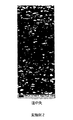
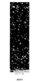
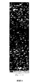
まず、3つの位置から採取したサンプルの板厚全体の粒子マップを、図1A,図1B,図1Cに示す。マップの上端は一方の圧延面であり、下端はもう一方の圧延面である。プレートは圧延されると、端部よりも中央が僅かに厚くなる点に注意されたい。試験幅(各マップの水平長さ)は、1.5mmである。マップは、プレートの放線方向(マップの垂直方向)の15°内に特定の結晶配向を有する粒子を示している。NDの15°内の100(100//ND成分として知られる)の粒子は赤、NDの15°内の111(111//ND成分として知られる)の粒子は青、NDの15°内の110の粒子は黄色で示されている。これらのいずれも満たさない粒子は灰色で示されている。これらの色ブロックが占める面積の割合が、以下に示す数値因子の計算の基礎となる。 First, particle maps of the entire plate thickness of samples taken from three positions are shown in FIGS. 1A, 1B, and 1C. The upper end of the map is one rolling surface, and the lower end is the other rolling surface. Note that when the plate is rolled, the center is slightly thicker than the edges. The test width (horizontal length of each map) is 1.5 mm. The map shows particles with a specific crystal orientation within 15 ° of the plate's normal direction (vertical direction of the map). 100 particles within 15 ° of ND (known as 100 // ND component) are red, 111 particles within 15 ° of ND (blue known as 111 // ND component) are blue, particles within 15 ° of ND The 110 particles are shown in yellow. Particles that do not satisfy any of these are shown in gray. The ratio of the area occupied by these color blocks is the basis for calculating the numerical factors shown below.
第2に、マップを、以下のように数学的に分析する。
1)マップを、上半分(H1)と下半分(H2)の2つの部分に分ける。
2)高さ135μm、全幅(この例では1.5mm)の切り欠孔を有するマスクを、切り欠孔の上端が、マップの下端に一致するように、マップの上に置く。ウィンドウの高さ(この場合135μm)にほぼ3つの粒子が入り、EBSDのステップが整数(この場合9ステップ)となるように選択されている点に注意されたい。
3)切り欠孔の赤色が占める面積の割合と青色が占める割合とを計算する。
4)マスクを1ステップ(この場合15μm)下に移動させ、計算を繰り返す。
5)切り欠孔の下端がマップの下端に一致するまで、操作4を繰り返す。
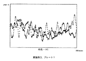
6)結果を示すグラフ(図1D)を作成する。例えば、このグラフは、中央のサンプルの上半分のグラフである。Y軸は、0%〜70%の面積の割合を示し、X軸は、マップの上(左側)から板厚中央(右側)までのマスク切り欠の位置を示す。赤い点は100を指し、青いドットは111を指す。
7)板厚の半分のそれぞれについて、このデータを分析して、以下を決定する。
a)100のデータを通る最良適合直線の勾配(1mm当たりの%)(100勾配)。
b)111のデータを通る最良適合直線の勾配(1mm当たりの%)(111勾配)。
c)最良適合直線からの100の各データ点の(y方向の)平均距離(%)(マイナスの場合、ゼロとしてカウントされる)(100BF)。
d)最良適合直線からの111の各データ点の(y方向の)平均距離(%)(マイナスの場合、ゼロとしてカウントされる)(111BF)。
3つの標本の上半分と下半分の両方の、この分析の結果を以下に示す。
Second, the map is analyzed mathematically as follows.
1) The map is divided into two parts, an upper half (H1) and a lower half (H2).
2) A mask having a notch hole with a height of 135 μm and a full width (1.5 mm in this example) is placed on the map so that the upper end of the notch hole coincides with the lower end of the map. Note that the window height (in this case 135 μm) contains approximately 3 particles and the EBSD steps are chosen to be an integer (in this case 9 steps).
3) Calculate the ratio of the area occupied by red in the cutout hole and the ratio occupied by blue.
4) Move the mask down one step (in this
5)
6) Create a graph (FIG. 1D) showing the results. For example, this graph is a graph of the upper half of the center sample. The Y axis indicates the area ratio of 0% to 70%, and the X axis indicates the position of the mask cutout from the top (left side) of the map to the center of the plate thickness (right side). The red dot points to 100 and the blue dot points to 111.
7) For each half of the thickness, analyze this data to determine:
a) Slope of best fit straight line through 100 data (% per mm) (100 slope).
b) The slope of the best fit straight line through the 111 data (% per mm) (111 slope).
c) Average distance (in y direction) of 100 data points from the best-fit straight line (%) (if negative, counts as zero) (100BF).
d) Average distance (in y direction) of 111 data points from the best-fit straight line (%) (if negative, counts as zero) (111BF).
The results of this analysis for both the upper and lower halves of the three specimens are shown below.

8)最後に、プレート内変動を計算する。この計算は、草案のASTM規格の方法には含まれない。この計算は、各サンプルの上半分と下半分のそれぞれについて、NDの15°内の100と111の面積の割合を示す以下の表から最も良好に評価される。「範囲」とは、行内の最大値と最小値の間の差である。切り欠を設けたマスクがこの計算では使用されない点に注意されたい。 8) Finally, calculate the intraplate variation. This calculation is not included in the draft ASTM standard method. This calculation is best evaluated from the following table showing the ratio of the area of 100 and 111 within 15 ° of ND for each of the upper and lower halves of each sample. “Range” is the difference between the maximum and minimum values in a row. Note that notched masks are not used in this calculation.
−「100勾配」と「111勾配」は、板厚方向勾配の値である。
−「100BF」と「111BF」は、帯形成度の値である。
−「A/P範囲」は、プレート内組織変動の値である。
-"100 gradient" and "111 gradient" are the values of the thickness direction gradient.
-"100BF" and "111BF" are values of the band formation degree.
-“A / P range” is the value of tissue variation in the plate.
実施例2(比較例)
米国特許第6,331,233号明細書の「詳細な説明」および図3に従ってプレートを作製した。平均結晶粒径は、約ASTM 5(60ミクロンALI)であった。
Example 2 (comparative example)
Plates were made according to the “detailed description” of US Pat. No. 6,331,233 and FIG. The average grain size was about ASTM 5 (60 micron ALI).
プレートの中央、プレート径の中間点およびプレートの端部からサンプルを採取し、水平方向と垂直方向の両方において15μmのステップを使用して、EBSDによって組織を求めた。プレートの板厚は9mmで、試験幅は3.6mmであった。180μmのウィンドウ高さを使用した。(グラフの面積の割合が0%〜70%ではなく、0%〜90%である点を除き)実施例1と同様に、結果を、図2A,図2B,図2C,図2Dと、表2A,表2Bとに示す。 Samples were taken from the center of the plate, the midpoint of the plate diameter, and the edge of the plate, and the tissue was determined by EBSD using 15 μm steps in both the horizontal and vertical directions. The plate thickness was 9 mm and the test width was 3.6 mm. A window height of 180 μm was used. Similar to Example 1, the results are shown in FIG. 2A, FIG. 2B, FIG. 2C, FIG. 2D and the table (except that the area ratio of the graph is 0% to 90% instead of 0% to 70%). 2A and Table 2B.
実施例3(比較例)
米国特許第6,521,173号明細書と上で説明したプロセス(ステップ1〜6)に従って、板厚7〜8mmの3枚のプレートを、粉末冶金プロセスによって作製し、直径165mmおよび厚さ81mmのパックを得た。パックは、従来法(厚さ33mmでの焼鈍ステップを含む)で圧延し、従来法で仕上げ加工を行った。
Example 3 (comparative example)
In accordance with US Pat. No. 6,521,173 and the process described above (steps 1-6), three plates with a thickness of 7-8 mm were made by a powder metallurgy process, 165 mm in diameter and 81 mm in thickness. Got a pack of. The pack was rolled by a conventional method (including an annealing step at a thickness of 33 mm) and finished by the conventional method.
各プレートの中央、各プレート径の中間点および各プレートの端部からサンプルを採取し(2サンプル、十分に離間)、水平方向と垂直方向の両方において10μmのステップを使用して、EBSDによって組織を求めた。試験幅が1.5mmではなく1.64mmである点と、グラフの面積割合が、0%〜70%ではなく0%〜60%を示す点を除き、結果を、実施例1と同様に表3A,表3Bに示す。プレート1の粒子マップを、図3A,図3B,図3C,図3Dに示し、中央−H1の結果を図3Eに示す。平均結晶粒径は、約ASTM 7(28ミクロンALI)であった。 Samples are taken from the center of each plate, the midpoint of each plate diameter, and the end of each plate (2 samples, well spaced) and tissue by EBSD using 10 μm steps in both horizontal and vertical directions. Asked. The results are the same as in Example 1 except that the test width is 1.64 mm instead of 1.5 mm and the area ratio of the graph is 0% to 60% instead of 0% to 70%. 3A, shown in Table 3B. The particle map of the plate 1 is shown in FIGS. 3A, 3B, 3C, and 3D, and the result of the center-H1 is shown in FIG. 3E. The average grain size was about ASTM 7 (28 micron ALI).
実施例4(比較例)
米国特許出願第10/079286号明細書の段落26,28,29に従って19枚のプレートを作製したが、合計4回の焼鈍(中間3枚、最終1回)を実施した点が、実施例1とは異なる。プレートの板厚は、約10mmであった。
Example 4 (comparative example)
Nineteen plates were produced according to paragraphs 26, 28, and 29 of US patent application Ser. No. 10/079286, but a total of four annealing (three intermediate, one final) was performed. Is different. The plate thickness was about 10 mm.
各プレートの端部から1サンプルを採取した。水平方向と垂直方向の両方において15μmのステップを使用して、EBSDによって組織を求めた。端部のサンプルのみを採取したため、A/P範囲を計算できなかった点を除き、実施例1と同じように、結果を、図4A,図4B,図4Cと、表4Aとに示す。平均結晶粒径は、約ASTM 5(53ミクロンALI)であった。 One sample was taken from the end of each plate. Tissues were determined by EBSD using 15 μm steps in both the horizontal and vertical directions. The results are shown in FIG. 4A, FIG. 4B, FIG. 4C, and Table 4A in the same manner as in Example 1 except that the A / P range could not be calculated because only the end samples were collected. The average grain size was about ASTM 5 (53 micron ALI).
実施例5(本発明)
上で簡単に説明したインゴット冶金プロセスを使用して、板厚6mmのプレートを作製した。このプロセスには、以下が含まれる。
1)マシニングによってインゴットの表面を洗浄。インゴット(直径195mm)を所定の長さ(374mm)に切断し、質量474ポンドとした。
2)ビレットを初期ビレット長の65%にアプセット鍛造(U1)。
3)ビレットを1370℃で焼鈍(A1)。
4)ビレットを直径197mmに鍛造戻し(FB1)。
5)ビレットを初期ビレット長の65%にアプセット鍛造(U2)。
6)ビレットを直径197mmに鍛造戻し(FB2)。
7)ビレットを初期ビレット長の65%にアプセット鍛造(U3)。
8)ビレットを1065℃で焼鈍(A2)。
9)ビレットを直径133mmに鍛造戻し(FB3)。マシニングによってインゴットの表面を洗浄し、このため、ビレットの直径が127mmに減少。
10)ビレットを38.1mmの長さに切断。
11)ビレットを1065℃で焼鈍(A3)。
12)所定の板厚に圧延。10°の傾斜角を使用した。各パスで、ピースの板厚を5%ずつ低下させた。各パスの後、垂直軸を中心に各ピースを90°回転させた。ピースは、4パスごとに反転させた。圧延後のピースの最終的な板厚は、6mmであった。
13)ビレットを1065℃で焼鈍(A4)。
14)平滑矯正。
15)プレートの中央、プレート径の中間点およびプレートの端部からサンプルを採取し、水平方向と垂直方向の両方において15μmのステップを使用して、EBSDによって組織を求めた。試験幅が1.5mmではなく1.64mmである点と、グラフの面積割合が、0%〜70%ではなく0%〜60%を示す点を除き、実施例1と同様に、結果をここに示す。粒子マップとグラフ化した結果を、図5A,図5B,図5C,図5Dにそれぞれ示す。平均結晶粒径は、約ASTM 6(約40μmALI)であった。
Example 5 (Invention)
A 6 mm thick plate was made using the ingot metallurgy process briefly described above. This process includes:
1) The surface of the ingot is cleaned by machining. An ingot (diameter 195 mm) was cut to a predetermined length (374 mm) to a mass of 474 pounds.
2) Upset forging (U1) to 65% of initial billet length.
3) Annealing the billet at 1370 ° C. (A1).
4) The billet is forged back to a diameter of 197 mm (FB1).
5) Upset forging (U2) to 65% of initial billet length.
6) The billet is forged back to a diameter of 197 mm (FB2).
7) Upset forging (U3) to 65% of initial billet length.
8) Annealing the billet at 1065 ° C. (A2).
9) The billet is forged back to 133 mm in diameter (FB3). The surface of the ingot is cleaned by machining, which reduces the billet diameter to 127 mm.
10) Cut the billet to a length of 38.1 mm.
11) The billet was annealed at 1065 ° C. (A3).
12) Roll to a predetermined plate thickness. A tilt angle of 10 ° was used. In each pass, the plate thickness of the piece was reduced by 5%. After each pass, each piece was rotated 90 ° about the vertical axis. The pieces were inverted every 4 passes. The final plate thickness of the piece after rolling was 6 mm.
13) Announce the billet at 1065 ° C. (A4).
14) Smoothing correction.
15) Samples were taken from the center of the plate, the midpoint of the plate diameter and the edge of the plate and the tissue was determined by EBSD using 15 μm steps in both the horizontal and vertical directions. The results are the same as in Example 1 except that the test width is 1.64 mm instead of 1.5 mm and that the area ratio of the graph shows 0% to 60% instead of 0% to 70%. Shown in The particle map and graphed results are shown in FIGS. 5A, 5B, 5C, and 5D, respectively. The average grain size was about ASTM 6 (about 40 μm ALI).
その他の測定手順の使用
実施例5で製作したプレート(本発明の実施例として)の中央のサンプルを、従来使用し、上で説明した方法で分析する。
Use of other measurement procedures A central sample of the plate produced in Example 5 (as an example of the present invention) is conventionally used and analyzed in the manner described above.
米国特許第6,348,113号明細書に記載の方法を使用する。すなわち、以下のとおりである。 The method described in US Pat. No. 6,348,113 is used. That is, it is as follows.
板厚を、20の区分(increments)に分けた。各区分について、10°の半値幅を使用してピーク強度を計算した(この方法は、113号明細書には記載されていないが、業界で標準的である)。 The plate thickness was divided into 20 increments. For each segment, peak intensities were calculated using a half width of 10 ° (this method is not described in the 113 specification but is standard in the industry).
111のピーク強度の変化は1.55〜5.07であったのに対し、113号明細書で最良の実施例の1つであるプレート125Bのピーク強度の変化は、0.85〜6.06であった。100のピーク強度の変化は2.35〜7.43であったのに対し、プレート125Bのピーク強度の変化は、0.37〜10.65であった。In(111/100)の変化は−1.09〜0.12であったのに対し、プレート125BのIn(111/100)の変化は−2.53〜3.11であった。 While the change in peak intensity of 111 was 1.55 to 5.07, the change in peak intensity of the plate 125B, which is one of the best examples of the 113 specification, was 0.85 to 6.7. 06. The change in peak intensity of 100 was 2.35 to 7.43, while the change in peak intensity of plate 125B was 0.37 to 10.65. The change of In (111/100) was -1.09 to 0.12, whereas the change of In (111/100) of the plate 125B was -2.53 to 3.11.
このため、113号明細書に記載した組織の定量化方法により、発明の実施例は、113号明細書における最良の実施例よりも板厚が極めて均一である。しかし、この方法は、上で使用したASTMの草案の方法と比べると、良好な比較方法でない。 For this reason, according to the tissue quantification method described in No. 113 specification, the embodiment of the invention has a much more uniform plate thickness than the best example in No. 113 specification. However, this method is not a good comparison method compared to the ASTM draft method used above.
米国特許出願第10/079286号明細書に記載の方法を使用する。すなわち、以下のとおりである。 The method described in US patent application Ser. No. 10/079286 is used. That is, it is as follows.
板厚を、8の区分に分けた。区分の数は286号明細書には記載されていないが、8が代表的であり、区分の数は重要ではない。区分ごとに、100の15°内の面積と、111の15°内の面積割合%を計算し、その差(分布)を更に計算する。 The plate thickness was divided into 8 sections. The number of sections is not described in the specification of 286, but 8 is representative and the number of sections is not important. For each section, the area within 15 ° of 100 and the area percentage% within 15 ° of 111 are calculated, and the difference (distribution) is further calculated.
最小の差は1%、最大の差は10%であるため、分布は9%となる。米国特許出願第10/079286号明細書には30%未満の分布が報告され、そのプロセスに従って作製したプレートは、一般に25%の分布となるため、本発明の実施例(9%)の組織の分布は、従来得られた分布よりも非常に小さいことが分かる。しかし、この比較方法は、上で使用したASTMの草案の方法と比べると、良好な方法でない。 Since the minimum difference is 1% and the maximum difference is 10%, the distribution is 9%. In US patent application Ser. No. 10/079286, a distribution of less than 30% is reported, and plates made according to that process generally have a distribution of 25%, so that the tissue of the example of the present invention (9%) It can be seen that the distribution is much smaller than the distribution obtained in the past. However, this comparison method is not as good as the ASTM draft method used above.
実施例6(本発明)
上で簡単に説明したインゴット冶金プロセスを使用して、板厚7.5mmのプレートを作製した。このプロセスには、以下が含まれる。
1)マシニングによってインゴットの表面を洗浄。インゴット(直径195mm)を所定の長さ(374mm)に切断し、質量474ポンドとした。
2)ビレットを初期ビレット長の65%にアプセット鍛造(U1)。
3)ビレットを1370℃で焼鈍(A1)。
4)ビレットを直径197mmに鍛造戻し(FB1)。
5)ビレットを初期ビレット長の65%にアプセット鍛造(U2)。
6)ビレットを直径197mmに鍛造戻し(FB2)。
7)ビレットを初期ビレット長の65%にアプセット鍛造(U3)。
8)ビレットを1065℃で焼鈍(A2)。
9)ビレットを直径133mmに鍛造戻し(FB3)。マシニングによってインゴットの表面を洗浄し、このため、ビレットの直径が127mmに減少。
10)ビレットを63.5mmの長さに切断。
11)ビレットを1065℃で焼鈍(A3)。
12)所定の板厚に圧延。5°の傾斜角を使用した。各パスで、ピースの板厚を5〜10%ずつ減少させた。各パスの後、各ピースを垂直軸に対して45°回転させた。ピースは、4パスごとに反転させた。圧延後のピースの最終的な板厚は、7.5mmであった。
13)ビレットを1010℃で焼鈍(A4)。
14)平滑矯正。
15)プレートの中央、プレート径の中間点およびプレートの端部からサンプルを採取し、水平方向と垂直方向の両方において15μmのステップを使用して、EBSDによって組織を求めた。試験幅が1.5mmではなく1.80mmである点を除き、結果を、実施例1と同様に、図6A,図6B,図6C,図6Dと、表6A,表6Bとに示す。平均結晶粒径は、約ASTM 6(約40μmALI)であった。
Example 6 (Invention)
A 7.5 mm thick plate was made using the ingot metallurgical process described briefly above. This process includes:
1) The surface of the ingot is cleaned by machining. An ingot (diameter 195 mm) was cut to a predetermined length (374 mm) to a mass of 474 pounds.
2) Upset forging (U1) to 65% of initial billet length.
3) Annealing the billet at 1370 ° C. (A1).
4) The billet is forged back to a diameter of 197 mm (FB1).
5) Upset forging (U2) to 65% of initial billet length.
6) The billet is forged back to a diameter of 197 mm (FB2).
7) Upset forging (U3) to 65% of initial billet length.
8) Annealing the billet at 1065 ° C. (A2).
9) The billet is forged back to 133 mm in diameter (FB3). The surface of the ingot is cleaned by machining, which reduces the billet diameter to 127 mm.
10) Cut the billet to a length of 63.5 mm.
11) The billet was annealed at 1065 ° C. (A3).
12) Roll to a predetermined plate thickness. An inclination angle of 5 ° was used. In each pass, the plate thickness of the piece was reduced by 5-10%. After each pass, each piece was rotated 45 ° about the vertical axis. The pieces were inverted every 4 passes. The final plate thickness of the piece after rolling was 7.5 mm.
13) Announce the billet at 1010 ° C. (A4).
14) Smoothing correction.
15) Samples were taken from the center of the plate, the midpoint of the plate diameter and the edge of the plate and the tissue was determined by EBSD using 15 μm steps in both the horizontal and vertical directions. The results are shown in FIG. 6A, FIG. 6B, FIG. 6C, FIG. 6D, and Tables 6A, 6B, as in Example 1, except that the test width is 1.80 mm instead of 1.5 mm. The average grain size was about ASTM 6 (about 40 μm ALI).
実施例7(本発明)
上で説明したのと同じ粉末冶金プロセス(ステップ1〜6)を使用して、板厚7.5mmのプレートを作製し、直径165mmおよび厚さ42mmのパックを得た。
Example 7 (present invention)
Using the same powder metallurgy process described above (steps 1-6), a plate with a plate thickness of 7.5 mm was made, resulting in a pack with a diameter of 165 mm and a thickness of 42 mm.
次に、これを所定の板厚に圧延した。5°の傾斜角を使用した。各パスで、ピースの板厚を5〜10%ずつ減少させた。各パスの後、各ピースを垂直軸に対して45°回転させた。ピースは、4パスごとに反転させた。圧延後のピースの最終的な板厚は、7.5mmであった。仕上げ加工(焼鈍など)は、従来の方法で実施した。 Next, this was rolled to a predetermined plate thickness. An inclination angle of 5 ° was used. In each pass, the plate thickness of the piece was reduced by 5-10%. After each pass, each piece was rotated 45 ° about the vertical axis. The pieces were inverted every 4 passes. The final plate thickness of the piece after rolling was 7.5 mm. Finishing (such as annealing) was performed by a conventional method.
プレートの中央、プレート径の中間点およびプレートの端部からサンプルを採取し、水平方向と垂直方向の両方において15μmのステップを使用して、EBSDによって組織を求めた。試験幅が1.5mmではなく1.64mmである点と、グラフの面積割合が、0%〜70%ではなく0%〜60%を示す点を除き、結果を、実施例1と同様に、ここに(図7A,7B,7C,7D)に示す。平均結晶粒径は、約ASTM 6 1/2(32ミクロンALI)であった。
Samples were taken from the center of the plate, the midpoint of the plate diameter, and the edge of the plate, and the tissue was determined by EBSD using 15 μm steps in both the horizontal and vertical directions. The results are the same as in Example 1, except that the test width is 1.64 mm instead of 1.5 mm, and the area ratio of the graph shows 0% to 60% instead of 0% to 70%. Here (shown in FIGS. 7A, 7B, 7C, 7D). The average grain size was about
実施例8(本発明)
上で説明したインゴット冶金プロセスを使用して、板厚8mmのプレートを3枚作製した。このプロセスには、以下が含まれる。
1)マシニングによってインゴットの表面を洗浄。インゴット(直径195mm)を所定の長さ(374mm)に切断し、質量474ポンドとした。
2)ビレットを初期ビレット長の65%にアプセット鍛造(U1)。
3)ビレットを1370℃で焼鈍(A1)。
4)ビレットを直径197mmに鍛造戻し(FB1)。
5)ビレットを初期ビレット長の65%にアプセット鍛造(U2)。
6)ビレットを直径197mmに鍛造戻し(FB2)。
7)ビレットを1065℃で焼鈍(A2)。
8)ビレットを初期ビレット長の65%にアプセット鍛造(U3)。
9)ビレットを直径133mmに鍛造戻し(FB3)。マシニングによってインゴットの表面を洗浄し、このため、ビレットの直径が127mmに減少。
10)ビレットを68.6mmの長さに切断。
11)ビレットを50.0mmにアプセット鍛造。
11)ビレットを1065℃で焼鈍(A3)。
12)従来の(直線)圧延を使用して、25.4mmの板厚に圧延。各パスで、ピースの板厚を20%ずつ低下させた。各パスの後、垂直軸を中心に各ピースを90°回転させた。
13)所定の最終板厚に圧延。5°の傾斜角を使用した。各パスで、ピースの板厚を10%ずつ低下させた。各パスの後、各ピースを垂直軸に対して45°回転させた。ピースは、パスごとに反転させた。圧延後のピースの最終的な板厚は、8mmであった。
14)ビレットを955℃で焼鈍(A4)。
15)平滑矯正。
Example 8 (Invention)
Three plates with a thickness of 8 mm were produced using the ingot metallurgical process described above. This process includes:
1) The surface of the ingot is cleaned by machining. An ingot (diameter 195 mm) was cut to a predetermined length (374 mm) to a mass of 474 pounds.
2) Upset forging (U1) to 65% of initial billet length.
3) Annealing the billet at 1370 ° C. (A1).
4) The billet is forged back to a diameter of 197 mm (FB1).
5) Upset forging (U2) to 65% of initial billet length.
6) The billet is forged back to a diameter of 197 mm (FB2).
7) The billet was annealed at 1065 ° C. (A2).
8) Upset forging (U3) to 65% of initial billet length.
9) The billet is forged back to 133 mm in diameter (FB3). The surface of the ingot is cleaned by machining, which reduces the billet diameter to 127 mm.
10) Cut the billet to a length of 68.6 mm.
11) Upset forging of billet to 50.0 mm.
11) The billet was annealed at 1065 ° C. (A3).
12) Roll using conventional (linear) rolling to a thickness of 25.4 mm. In each pass, the plate thickness of the piece was reduced by 20%. After each pass, each piece was rotated 90 ° about the vertical axis.
13) Roll to a predetermined final thickness. An inclination angle of 5 ° was used. In each pass, the plate thickness of the piece was reduced by 10%. After each pass, each piece was rotated 45 ° about the vertical axis. The piece was inverted after each pass. The final plate thickness of the piece after rolling was 8 mm.
14) Announce the billet at 955 ° C. (A4).
15) Smoothing correction.
1プレートの場合、プレートの中央、プレート径の中間点およびプレートの端部からサンプルを採取し(2サンプル、十分に離間)、水平方向と垂直方向の両方において15μmのステップを使用して、EBSDによって組織を求めた。実施例1と同様に、結果を、図8A,8B,8C,8D,8Eと、表8A,8Bとに示す。ほかの2枚のプレートの場合、端部のサンプル(2サンプル、十分に離間)のみを採取した。平均結晶粒径は、約ASTM 7 1/2(24ミクロンALI)であった。 In the case of one plate, samples are taken from the center of the plate, the midpoint of the plate diameter and the end of the plate (2 samples, well spaced) and using 15 μm steps in both horizontal and vertical directions, EBSD Asked for an organization. Similar to Example 1, the results are shown in FIGS. 8A, 8B, 8C, 8D, 8E and Tables 8A, 8B. For the other two plates, only end samples (2 samples, well separated) were taken. The average grain size was about ASTM 71/2 (24 micron ALI).
まとめ
以下の概要表では、本発明の実施例を、4つの従来技術の実施例と、便利に比較することができる。平均勾配の計算では、各勾配値の絶対値を使用する。下に示す最大勾配は、採取したサンプルのいずれかの最大値であり、本発明の全実施例の場合には、端部、径方向の中央および中心の位置を含む。各値が低いほど、プレートの組織の均一性が高い。
Summary In the following summary table, examples of the present invention can be conveniently compared with four prior art examples. In calculating the average slope, the absolute value of each slope value is used. The maximum slope shown below is the maximum value of any of the collected samples and includes the end, radial center and center positions for all examples of the present invention. The lower each value, the more uniform the tissue of the plate.
「N/A」は「なし」である。
“N / A” is “none”.
表9(実施例3,7は粉末冶金を使用し、ほかはインゴット冶金法を使用した)から、以下のことがわかる。
1)比較例は、全て平均勾配が1mm当たり5%を超えている。
2)比較例のうち、実施例3(粉末冶金法)は、実施例1,2,3(インゴット冶金法)よりも均一な組織を有する。
3)本発明の実施例は、全て平均勾配が1mm当たり5%未満であり、実施例の一部では、粉末冶金法およびインゴット冶金法の両方について、平均勾配が、関連する比較例の半分未満である。
4)本発明の実施例のうち、実施例7(粉末冶金法)は、実施例5,6,8(インゴット冶金法)よりも均一な組織を有する。
6)本発明の実施例の一部では、帯形成係数とA/P範囲が、関連する比較例と同等であるのみならず、これらよりも実際に低い。
From Table 9 (Examples 3 and 7 use powder metallurgy, and others use ingot metallurgy), the following can be seen.
1) In all the comparative examples, the average gradient exceeds 5% per mm.
2) Of the comparative examples, Example 3 (powder metallurgy) has a more uniform structure than Examples 1, 2, and 3 (ingot metallurgy).
3) All examples of the present invention have an average gradient of less than 5% per mm, and in some of the examples, the average gradient is less than half that of the related comparative examples for both powder metallurgy and ingot metallurgy. It is.
4) Of the examples of the present invention, Example 7 (powder metallurgy method) has a more uniform structure than Examples 5, 6 and 8 (ingot metallurgy method).
6) In some of the examples of the present invention, the banding factor and A / P range are not only comparable to the related comparative examples, but actually lower than these.
また、実施例3,4,8はそれぞれ、プレートを複数枚作製したため、これらの実施例間の比較により、プレート間の組織の変動の統計解析とこのため比較が可能となるため、有益である。端部のサンプル(実施例4から19サンプル、その他の実施例のそれぞれから6サンプル)を、表10に比較する。 In addition, each of Examples 3, 4 and 8 is useful because a plurality of plates were prepared, and comparison between these Examples enables statistical analysis of tissue fluctuations between the plates and thus comparison. . The edge samples (Examples 4 to 19 samples, 6 samples from each of the other examples) are compared in Table 10.
12のデータ点からの標準偏差は、あまり正確でないが、(表10の標準偏差に示すように)実施例8の変動が実施例3,4の変動と似ていることがわかる。表において、実施例8の平均勾配が実施例3,4と比べて低いことが強調されている。 The standard deviation from 12 data points is not very accurate, but it can be seen that the variation of Example 8 is similar to that of Examples 3 and 4 (as shown in the standard deviation of Table 10). In the table, it is emphasized that the average slope of Example 8 is low compared to Examples 3 and 4.
本発明の特定の実施形態を、説明のために上で説明したが、添付の特許請求の範囲に記載の本発明を逸脱しない範囲で、本発明の詳細をさまざまに変更することができることは、当業者に明らかであろう。 While particular embodiments of the present invention have been described above for purposes of illustration, the details of the invention may be modified in various ways without departing from the invention as set forth in the appended claims. It will be apparent to those skilled in the art.
Claims (10)
Applications Claiming Priority (3)
| Application Number | Priority Date | Filing Date | Title |
|---|---|---|---|
| US96361607P | 2007-08-06 | 2007-08-06 | |
| US60/963,616 | 2007-08-06 | ||
| PCT/US2008/009388 WO2009020587A1 (en) | 2007-08-06 | 2008-08-05 | Refractory metal plates with improved uniformity of texture |
Related Child Applications (1)
| Application Number | Title | Priority Date | Filing Date |
|---|---|---|---|
| JP2013143996A Division JP6085531B2 (en) | 2007-08-06 | 2013-07-09 | Refractory metal plate with improved tissue uniformity |
Publications (2)
| Publication Number | Publication Date |
|---|---|
| JP2010535943A JP2010535943A (en) | 2010-11-25 |
| JP5389802B2 true JP5389802B2 (en) | 2014-01-15 |
Family
ID=40020260
Family Applications (6)
| Application Number | Title | Priority Date | Filing Date |
|---|---|---|---|
| JP2010519963A Active JP5389802B2 (en) | 2007-08-06 | 2008-08-05 | Refractory metal plate with improved tissue uniformity |
| JP2010519977A Pending JP2010535633A (en) | 2007-08-06 | 2008-08-06 | Method of controlling the structure of plates and sheets by tilt rolling |
| JP2013051303A Active JP5766733B2 (en) | 2007-08-06 | 2013-03-14 | Method of controlling the structure of plates and sheets by tilt rolling |
| JP2013143996A Active JP6085531B2 (en) | 2007-08-06 | 2013-07-09 | Refractory metal plate with improved tissue uniformity |
| JP2015122175A Active JP6140771B2 (en) | 2007-08-06 | 2015-06-17 | Method of controlling the structure of plates and sheets by tilt rolling |
| JP2016020371A Pending JP2016148110A (en) | 2007-08-06 | 2016-02-05 | High melting metal plate with improved uniformity of tissue |
Family Applications After (5)
| Application Number | Title | Priority Date | Filing Date |
|---|---|---|---|
| JP2010519977A Pending JP2010535633A (en) | 2007-08-06 | 2008-08-06 | Method of controlling the structure of plates and sheets by tilt rolling |
| JP2013051303A Active JP5766733B2 (en) | 2007-08-06 | 2013-03-14 | Method of controlling the structure of plates and sheets by tilt rolling |
| JP2013143996A Active JP6085531B2 (en) | 2007-08-06 | 2013-07-09 | Refractory metal plate with improved tissue uniformity |
| JP2015122175A Active JP6140771B2 (en) | 2007-08-06 | 2015-06-17 | Method of controlling the structure of plates and sheets by tilt rolling |
| JP2016020371A Pending JP2016148110A (en) | 2007-08-06 | 2016-02-05 | High melting metal plate with improved uniformity of tissue |
Country Status (7)
| Country | Link |
|---|---|
| US (5) | US9095885B2 (en) |
| EP (3) | EP2185300B1 (en) |
| JP (6) | JP5389802B2 (en) |
| KR (3) | KR101201577B1 (en) |
| CN (2) | CN101772385B (en) |
| CA (1) | CA2694355A1 (en) |
| WO (2) | WO2009020587A1 (en) |
Families Citing this family (28)
| Publication number | Priority date | Publication date | Assignee | Title |
|---|---|---|---|---|
| US7837929B2 (en) | 2005-10-20 | 2010-11-23 | H.C. Starck Inc. | Methods of making molybdenum titanium sputtering plates and targets |
| JP5389802B2 (en) | 2007-08-06 | 2014-01-15 | エイチ.シー. スターク インコーポレイテッド | Refractory metal plate with improved tissue uniformity |
| WO2010051040A1 (en) * | 2008-11-03 | 2010-05-06 | Tosoh Smd, Inc. | Method of making a sputter target and sputter targets made thereby |
| US8449817B2 (en) | 2010-06-30 | 2013-05-28 | H.C. Stark, Inc. | Molybdenum-containing targets comprising three metal elements |
| US8449818B2 (en) | 2010-06-30 | 2013-05-28 | H. C. Starck, Inc. | Molybdenum containing targets |
| WO2012154817A1 (en) | 2011-05-10 | 2012-11-15 | H.C. Starck, Inc. | Composite target |
| US9216445B2 (en) | 2011-08-03 | 2015-12-22 | Ut-Battelle, Llc | Method of forming magnesium alloy sheets |
| CN103105776B (en) * | 2011-11-15 | 2015-03-04 | 宝山钢铁股份有限公司 | Acid-pickling edge-shearing control method of non-oriented silicon steel |
| US9334565B2 (en) | 2012-05-09 | 2016-05-10 | H.C. Starck Inc. | Multi-block sputtering target with interface portions and associated methods and articles |
| CN102719772B (en) * | 2012-07-04 | 2013-08-07 | 北京科技大学 | Copper material with two different surface roughnesses and asymmetrical gradient distribution and forming method thereof |
| JP2014110276A (en) | 2012-11-30 | 2014-06-12 | Samsung Display Co Ltd | Hole transport material for organic electroluminescent element and organic electroluminescent element using the same |
| CN104690088A (en) * | 2013-12-05 | 2015-06-10 | 北京有色金属研究总院 | Simulation experiment method of rolling technology |
| CN104801541A (en) * | 2014-01-23 | 2015-07-29 | 大连理工大学 | Rolling method for preparing high room temperature ductility magnesium alloy panel |
| US20160208377A1 (en) * | 2014-03-27 | 2016-07-21 | Jx Nippon Mining & Metals Corporation | Tantalum sputtering target and method for producing same |
| JP6573629B2 (en) * | 2014-04-11 | 2019-09-11 | ハー ツェー シュタルク インコーポレイテッドH.C. Starck, Inc. | High purity refractory metal powders and their use in sputtering targets that can have disordered texture |
| JP6602550B2 (en) | 2014-04-28 | 2019-11-06 | 株式会社アライドマテリアル | Material for sputtering target |
| CN104226565B (en) * | 2014-08-27 | 2016-04-06 | 史建平 | UV curing is with flattening anti-collision structure |
| CN104646416B (en) * | 2015-01-16 | 2016-08-17 | 湖南科技大学 | A kind of sheet metal Strong shear roll-forming method and device |
| DE102015101580B3 (en) * | 2015-02-04 | 2016-06-02 | Hydro Aluminium Rolled Products Gmbh | Method and device for embossing a strip |
| WO2016190160A1 (en) * | 2015-05-22 | 2016-12-01 | Jx金属株式会社 | Tantalum sputtering target, and production method therefor |
| WO2016190159A1 (en) * | 2015-05-22 | 2016-12-01 | Jx金属株式会社 | Tantalum sputtering target, and production method therefor |
| JP6638639B2 (en) * | 2016-12-19 | 2020-01-29 | トヨタ自動車株式会社 | Method for manufacturing differential thickness metal sheet, method for manufacturing pressed part, and processing machine |
| CN106756832B (en) * | 2016-12-27 | 2019-03-12 | 宁夏东方钽业股份有限公司 | A kind of preparation method of target |
| US11062889B2 (en) | 2017-06-26 | 2021-07-13 | Tosoh Smd, Inc. | Method of production of uniform metal plates and sputtering targets made thereby |
| CN109213086B (en) * | 2017-06-29 | 2020-10-23 | 台湾积体电路制造股份有限公司 | Processing system and processing method |
| CN108465700B (en) * | 2018-03-13 | 2020-09-08 | 重庆大学 | Tantalum plate rolling method for obtaining sputtering target material with uniform structure and texture |
| US20210290934A1 (en) * | 2018-07-17 | 2021-09-23 | Viaderm Llc | Indwelling hyper-dimensional cardiac physiologic data logging and transmission system and method of doing business |
| CN110586942B (en) * | 2018-12-17 | 2020-08-14 | 南京中科煜宸激光技术有限公司 | Method for manufacturing gradient pipe through 3D printing and regulating and controlling microstructure |
Family Cites Families (62)
| Publication number | Priority date | Publication date | Assignee | Title |
|---|---|---|---|---|
| US1852271A (en) | 1930-02-18 | 1932-04-05 | American Rolling Mill Co | Process of rolling sheets |
| US2075066A (en) * | 1934-09-15 | 1937-03-30 | American Rolling Mill Co | Method of rolling metal |
| US2123291A (en) | 1935-02-23 | 1938-07-12 | United Eng Foundry Co | Apparatus for rolling strip |
| US2250541A (en) | 1938-10-28 | 1941-07-29 | Westinghouse Electric & Mfg Co | Tensioning device |
| US3811305A (en) | 1972-10-10 | 1974-05-21 | Bethlehem Steel Corp | Movable descaler spray header |
| AT357587B (en) | 1976-02-18 | 1980-07-25 | Voest Alpine Ag | METHOD FOR PRODUCING SHEETS FROM AUSTENITIC STEELS WITH FINE GRAIN |
| SU738695A1 (en) | 1977-08-12 | 1980-06-05 | Челябинский Политехнический Институт Им.Ленинского Комсомола | Rolling method |
| JPS54149352A (en) * | 1978-05-17 | 1979-11-22 | Ishikawajima Harima Heavy Ind Co Ltd | Rolling method by changing friction forces of upper and lower rolls |
| JPS55139102A (en) * | 1979-04-17 | 1980-10-30 | Mitsubishi Heavy Ind Ltd | Rolling method for strip |
| JPS55165217A (en) | 1979-06-12 | 1980-12-23 | Ishikawajima Harima Heavy Ind Co Ltd | Lubricating method for rolled material |
| SU931244A1 (en) * | 1980-12-10 | 1982-05-30 | Институт Черной Металлургии Мчм Ссср | Method of rolling strip material in multistand mill |
| JPS58116920A (en) * | 1981-12-28 | 1983-07-12 | Mitsubishi Heavy Ind Ltd | Pushing apparatus of rolling mill |
| US4473416A (en) | 1982-07-08 | 1984-09-25 | Nippon Steel Corporation | Process for producing aluminum-bearing grain-oriented silicon steel strip |
| JPS63104703A (en) * | 1986-10-23 | 1988-05-10 | Nippon Steel Corp | Method for preventing camber at front end in rolling with differential diameter roll |
| CH677530A5 (en) | 1988-11-17 | 1991-05-31 | Eidgenoess Munitionsfab Thun | |
| US5242481A (en) | 1989-06-26 | 1993-09-07 | Cabot Corporation | Method of making powders and products of tantalum and niobium |
| JPH0332404A (en) | 1989-06-27 | 1991-02-13 | Nkk Corp | Method for rolling metallic sheet |
| JPH0641684Y2 (en) * | 1990-10-15 | 1994-11-02 | 新日本製鐵株式会社 | High-performance induction device for profiles |
| US5850755A (en) | 1995-02-08 | 1998-12-22 | Segal; Vladimir M. | Method and apparatus for intensive plastic deformation of flat billets |
| US6569270B2 (en) | 1997-07-11 | 2003-05-27 | Honeywell International Inc. | Process for producing a metal article |
| WO1999013998A1 (en) | 1997-09-16 | 1999-03-25 | Ishikawajima-Harima Heavy Industries Co., Ltd. | Plate thickness pressing device and method |
| JPH11188417A (en) * | 1997-12-25 | 1999-07-13 | Kawasaki Steel Corp | Carrier guide apparatus for hot rolling thin steel plate |
| US6348139B1 (en) | 1998-06-17 | 2002-02-19 | Honeywell International Inc. | Tantalum-comprising articles |
| DE19840538A1 (en) | 1998-08-28 | 2000-03-09 | Mannesmann Ag | Roll stand with crossed support and / or work rolls |
| US6348113B1 (en) | 1998-11-25 | 2002-02-19 | Cabot Corporation | High purity tantalum, products containing the same, and methods of making the same |
| US5992201A (en) | 1998-12-07 | 1999-11-30 | Danieli United | Rolling and shearing process and apparatus background |
| JP2001020065A (en) | 1999-07-07 | 2001-01-23 | Hitachi Metals Ltd | Target for sputtering, its production and high melting point metal powder material |
| US6521173B2 (en) | 1999-08-19 | 2003-02-18 | H.C. Starck, Inc. | Low oxygen refractory metal powder for powder metallurgy |
| JP4698779B2 (en) * | 1999-09-08 | 2011-06-08 | Jx日鉱日石金属株式会社 | Magnetic sputtering target and manufacturing method thereof |
| AUPQ436399A0 (en) | 1999-12-01 | 1999-12-23 | Bhp Steel (Jla) Pty Limited | Hot rolling thin strip |
| US6331233B1 (en) | 2000-02-02 | 2001-12-18 | Honeywell International Inc. | Tantalum sputtering target with fine grains and uniform texture and method of manufacture |
| AUPQ546900A0 (en) | 2000-02-07 | 2000-03-02 | Bhp Steel (Jla) Pty Limited | Rolling strip material |
| US6462339B1 (en) | 2000-09-20 | 2002-10-08 | Cabot Corporation | Method for quantifying the texture homogeneity of a polycrystalline material |
| US6946039B1 (en) | 2000-11-02 | 2005-09-20 | Honeywell International Inc. | Physical vapor deposition targets, and methods of fabricating metallic materials |
| CN1257998C (en) | 2001-01-11 | 2006-05-31 | 卡伯特公司 | Tantalum and niobium billets and methods of producing the same |
| CA2438819A1 (en) | 2001-02-20 | 2002-09-12 | Peter R. Jepson | Refractory metal plates with uniform texture and methods of making the same |
| NL1018817C2 (en) | 2001-08-24 | 2003-02-25 | Corus Technology B V | Method for processing a continuously cast metal slab or belt, and plate or belt thus produced. |
| NL1018814C2 (en) * | 2001-08-24 | 2003-02-25 | Corus Technology B V | Device for processing a metal slab, plate or strip and product made with it. |
| US7081148B2 (en) * | 2001-09-18 | 2006-07-25 | Praxair S.T. Technology, Inc. | Textured-grain-powder metallurgy tantalum sputter target |
| US6770154B2 (en) | 2001-09-18 | 2004-08-03 | Praxair S.T. Technology, Inc. | Textured-grain-powder metallurgy tantalum sputter target |
| US6976380B1 (en) * | 2002-01-24 | 2005-12-20 | The Texas A&M University System | Developing the texture of a material |
| JP2003305503A (en) * | 2002-04-09 | 2003-10-28 | Mitsubishi Alum Co Ltd | Highly formable aluminum alloy plate and method for producing the same |
| TWI341337B (en) * | 2003-01-07 | 2011-05-01 | Cabot Corp | Powder metallurgy sputtering targets and methods of producing same |
| US7228722B2 (en) * | 2003-06-09 | 2007-06-12 | Cabot Corporation | Method of forming sputtering articles by multidirectional deformation |
| JP2005103573A (en) * | 2003-09-29 | 2005-04-21 | Daido Steel Co Ltd | Rolling mill and rolling method |
| CN101857950B (en) | 2003-11-06 | 2012-08-08 | Jx日矿日石金属株式会社 | Tantalum sputtering target |
| WO2005080961A2 (en) | 2004-02-18 | 2005-09-01 | Cabot Corporation | Ultrasonic method for detecting banding in metals |
| US7381282B2 (en) | 2004-04-07 | 2008-06-03 | Hitachi Metals, Ltd. | Co alloy target and its production method, soft magnetic film for perpendicular magnetic recording and perpendicular magnetic recording medium |
| US8252126B2 (en) | 2004-05-06 | 2012-08-28 | Global Advanced Metals, Usa, Inc. | Sputter targets and methods of forming same by rotary axial forging |
| US8088232B2 (en) * | 2004-08-31 | 2012-01-03 | H.C. Starck Inc. | Molybdenum tubular sputtering targets with uniform grain size and texture |
| US20060042728A1 (en) * | 2004-08-31 | 2006-03-02 | Brad Lemon | Molybdenum sputtering targets |
| US7998287B2 (en) | 2005-02-10 | 2011-08-16 | Cabot Corporation | Tantalum sputtering target and method of fabrication |
| US20060201589A1 (en) * | 2005-03-11 | 2006-09-14 | Honeywell International Inc. | Components comprising metallic material, physical vapor deposition targets, thin films, and methods of forming metallic components |
| US7928602B2 (en) | 2007-03-30 | 2011-04-19 | Steelcase Development Corporation | Power floor method and assembly |
| US8197894B2 (en) | 2007-05-04 | 2012-06-12 | H.C. Starck Gmbh | Methods of forming sputtering targets |
| US20090010792A1 (en) | 2007-07-02 | 2009-01-08 | Heraeus Inc. | Brittle metal alloy sputtering targets and method of fabricating same |
| JP5389802B2 (en) * | 2007-08-06 | 2014-01-15 | エイチ.シー. スターク インコーポレイテッド | Refractory metal plate with improved tissue uniformity |
| US8250895B2 (en) | 2007-08-06 | 2012-08-28 | H.C. Starck Inc. | Methods and apparatus for controlling texture of plates and sheets by tilt rolling |
| JP5342810B2 (en) | 2008-06-09 | 2013-11-13 | 株式会社コベルコ科研 | Method for producing Al-based alloy sputtering target material |
| MX347082B (en) | 2010-02-15 | 2017-04-11 | Federal-Mogul Corp | A master alloy for producing sinter hardened steel parts and process for the production of sinter hardened parts. |
| JP5165100B1 (en) | 2011-11-01 | 2013-03-21 | 三菱マテリアル株式会社 | Sputtering target and manufacturing method thereof |
| CN102513537B (en) | 2011-12-06 | 2013-07-17 | 中国航空工业集团公司北京航空材料研究院 | Method for preparing TiAl alloy plate by argon atomization in powder metallurgy |
-
2008
- 2008-08-05 JP JP2010519963A patent/JP5389802B2/en active Active
- 2008-08-05 EP EP08795025.9A patent/EP2185300B1/en active Active
- 2008-08-05 KR KR1020107002603A patent/KR101201577B1/en active IP Right Grant
- 2008-08-05 WO PCT/US2008/009388 patent/WO2009020587A1/en active Application Filing
- 2008-08-05 US US12/221,646 patent/US9095885B2/en active Active
- 2008-08-06 EP EP08795075.4A patent/EP2176009B1/en active Active
- 2008-08-06 WO PCT/US2008/009446 patent/WO2009020619A1/en active Application Filing
- 2008-08-06 KR KR1020127018608A patent/KR101365774B1/en active IP Right Grant
- 2008-08-06 JP JP2010519977A patent/JP2010535633A/en active Pending
- 2008-08-06 CN CN2008801019474A patent/CN101772385B/en not_active Expired - Fee Related
- 2008-08-06 CA CA2694355A patent/CA2694355A1/en not_active Abandoned
- 2008-08-06 KR KR1020107002711A patent/KR101204245B1/en active IP Right Grant
- 2008-08-06 EP EP15188449.1A patent/EP2998039B1/en active Active
- 2008-08-06 CN CN201310268498.5A patent/CN103350108B/en not_active Expired - Fee Related
-
2013
- 2013-03-14 JP JP2013051303A patent/JP5766733B2/en active Active
- 2013-07-09 JP JP2013143996A patent/JP6085531B2/en active Active
-
2015
- 2015-06-17 JP JP2015122175A patent/JP6140771B2/en active Active
- 2015-06-26 US US14/751,224 patent/US9767999B2/en active Active
-
2016
- 2016-02-05 JP JP2016020371A patent/JP2016148110A/en active Pending
-
2017
- 2017-08-22 US US15/682,605 patent/US10236164B2/en active Active
-
2019
- 2019-01-29 US US16/260,274 patent/US10943772B2/en active Active
-
2021
- 2021-01-22 US US17/155,254 patent/US11443929B2/en active Active
Also Published As
Similar Documents
| Publication | Publication Date | Title |
|---|---|---|
| JP6085531B2 (en) | Refractory metal plate with improved tissue uniformity | |
| JP5114812B2 (en) | Method for producing deformed metal member | |
| JP5578496B2 (en) | Tantalum sputtering target | |
| CN101278071B (en) | Sputtering target | |
| EP2253731A1 (en) | Tantalum spattering target | |
| JP2000313954A (en) | Production of nickel/vanadium sputtering target with minimal alpha emission | |
| JP6602550B2 (en) | Material for sputtering target | |
| JP5038553B2 (en) | Manufacturing method of sputtering target | |
| WO2000031316A1 (en) | Co-Ti ALLOY SPUTTERING TARGET AND MANUFACTURING METHOD THEREOF | |
| WO2023058698A1 (en) | Sputtering target, method for producing same, and method for producing sputtering film using sputtering target |
Legal Events
| Date | Code | Title | Description |
|---|---|---|---|
| A521 | Request for written amendment filed |
Free format text: JAPANESE INTERMEDIATE CODE: A523 Effective date: 20100916 |
|
| A621 | Written request for application examination |
Free format text: JAPANESE INTERMEDIATE CODE: A621 Effective date: 20100916 |
|
| A977 | Report on retrieval |
Free format text: JAPANESE INTERMEDIATE CODE: A971007 Effective date: 20121219 |
|
| A131 | Notification of reasons for refusal |
Free format text: JAPANESE INTERMEDIATE CODE: A131 Effective date: 20130109 |
|
| A601 | Written request for extension of time |
Free format text: JAPANESE INTERMEDIATE CODE: A601 Effective date: 20130404 |
|
| A602 | Written permission of extension of time |
Free format text: JAPANESE INTERMEDIATE CODE: A602 Effective date: 20130411 |
|
| A601 | Written request for extension of time |
Free format text: JAPANESE INTERMEDIATE CODE: A601 Effective date: 20130509 |
|
| A602 | Written permission of extension of time |
Free format text: JAPANESE INTERMEDIATE CODE: A602 Effective date: 20130516 |
|
| A601 | Written request for extension of time |
Free format text: JAPANESE INTERMEDIATE CODE: A601 Effective date: 20130607 |
|
| A602 | Written permission of extension of time |
Free format text: JAPANESE INTERMEDIATE CODE: A602 Effective date: 20130614 |
|
| A521 | Request for written amendment filed |
Free format text: JAPANESE INTERMEDIATE CODE: A523 Effective date: 20130709 |
|
| TRDD | Decision of grant or rejection written | ||
| A01 | Written decision to grant a patent or to grant a registration (utility model) |
Free format text: JAPANESE INTERMEDIATE CODE: A01 Effective date: 20130925 |
|
| A61 | First payment of annual fees (during grant procedure) |
Free format text: JAPANESE INTERMEDIATE CODE: A61 Effective date: 20131009 |
|
| R150 | Certificate of patent or registration of utility model |
Ref document number: 5389802 Country of ref document: JP Free format text: JAPANESE INTERMEDIATE CODE: R150 Free format text: JAPANESE INTERMEDIATE CODE: R150 |
|
| R250 | Receipt of annual fees |
Free format text: JAPANESE INTERMEDIATE CODE: R250 |
|
| R250 | Receipt of annual fees |
Free format text: JAPANESE INTERMEDIATE CODE: R250 |
|
| R250 | Receipt of annual fees |
Free format text: JAPANESE INTERMEDIATE CODE: R250 |
|
| R250 | Receipt of annual fees |
Free format text: JAPANESE INTERMEDIATE CODE: R250 |
|
| R250 | Receipt of annual fees |
Free format text: JAPANESE INTERMEDIATE CODE: R250 |
|
| R250 | Receipt of annual fees |
Free format text: JAPANESE INTERMEDIATE CODE: R250 |
|
| R250 | Receipt of annual fees |
Free format text: JAPANESE INTERMEDIATE CODE: R250 |
|
| R250 | Receipt of annual fees |
Free format text: JAPANESE INTERMEDIATE CODE: R250 |