US8942895B2 - Display system of hydraulic shovel, and control method therefor - Google Patents
Display system of hydraulic shovel, and control method therefor Download PDFInfo
- Publication number
- US8942895B2 US8942895B2 US13/819,456 US201213819456A US8942895B2 US 8942895 B2 US8942895 B2 US 8942895B2 US 201213819456 A US201213819456 A US 201213819456A US 8942895 B2 US8942895 B2 US 8942895B2
- Authority
- US
- United States
- Prior art keywords
- blade edge
- bucket
- target surface
- distance
- hydraulic shovel
- Prior art date
- Legal status (The legal status is an assumption and is not a legal conclusion. Google has not performed a legal analysis and makes no representation as to the accuracy of the status listed.)
- Active
Links
Images


Classifications
-
- E—FIXED CONSTRUCTIONS
- E02—HYDRAULIC ENGINEERING; FOUNDATIONS; SOIL SHIFTING
- E02F—DREDGING; SOIL-SHIFTING
- E02F9/00—Component parts of dredgers or soil-shifting machines, not restricted to one of the kinds covered by groups E02F3/00 - E02F7/00
- E02F9/26—Indicating devices
-
- E—FIXED CONSTRUCTIONS
- E02—HYDRAULIC ENGINEERING; FOUNDATIONS; SOIL SHIFTING
- E02F—DREDGING; SOIL-SHIFTING
- E02F9/00—Component parts of dredgers or soil-shifting machines, not restricted to one of the kinds covered by groups E02F3/00 - E02F7/00
- E02F9/26—Indicating devices
- E02F9/264—Sensors and their calibration for indicating the position of the work tool
Definitions
- the present invention relates to a display system in a hydraulic shovel and a control method therefor.
- a work machine comprising a bucket is typically operated by an operator operating an operating lever. At such times, it is difficult for the operator to determine whether, when digging a ditch of a predetermined depth or a slope of a predetermined grade, digging the target shape is being accurately performed only by observing the motions of the work machine.
- the positional relationship between the target digging surface and a bucket blade edge is displayed as an image on a monitor.
- a numerical value displaying the distance between the target digging surface and the blade edge of the bucket is also displayed on the monitor. An operator is thereby capable of properly operating to dig a predetermined target digging surface.
- the distance between the blade edge of the bucket and the target digging surface will not be the same at all positions along the blade edge of the bucket in its widthwise direction. For example, taking the distance between the center of the blade edge of the bucket in its widthwise direction and the target digging surface as a reference distance, the distance between an end of the blade edge of the bucket in its widthwise direction and the target digging surface may be less than the reference distance. Conversely; the distance between the end of the blade edge of the bucket in its widthwise direction and the target digging surface may also be greater than the reference distance.
- An object of the present invention is to provide a hydraulic shovel display system and a control method therefor allowing digging operation to be performed with precision
- a hydraulic shovel display system is a display system in a hydraulic shovel having a work machine comprising a bucket and a main body to which the work machine is attached.
- the display system comprises a position detector unit, a storage unit, a calculation unit, and a display unit.
- the position detector unit detects information pertaining to a current position of the hydraulic shovel.
- the storage unit stores positional information for a design surface indicating a target shape of a work object.
- the calculation unit calculates a position of the blade edge of the bucket on the basis of information pertaining to the current position of the hydraulic shovel.
- the calculation unit calculates the distance between the design surface and the position closest to the design surface among positions of the blade edge in the widthwise direction of the blade edge on the basis of positional information for the blade edge and the design surface.
- the display unit displays a guidance picture.
- the guidance picture includes an image showing a positional relationship between the design surface and the blade edge of the bucket, and information indicating the distance between the design surface and the closest position.
- a display system in a hydraulic shovel according to a second aspect of the present invention is the display system in the hydraulic shovel according to the first aspect, wherein the image showing the positional relationship between the design surface and the blade edge of the bucket includes a head-on view of the bucket. The closest position is also displayed in the head-on view of the bucket.
- a display system in a hydraulic shovel according to a third aspect of the present invention is the display system in the hydraulic shovel according to the first aspect, wherein part of the design surface is selected as a target surface. Information indicating the distance between the target surface and the position closest to the target surface among positions of the blade edge in the widthwise direction of the blade edge is also displayed in the guidance picture.
- a display system in a hydraulic shovel according to a fourth aspect of the present invention is the display system in the hydraulic shovel according to the third aspect, wherein information indicating the distance between a non-target surface excluding the target surface of the design surface and a position closest to the non-target surface among positions of the blade edge in the widthwise direction of the blade edge is displayed using a feature different from the information indicating the distance between the target surface and the position closest to the target surface when the non-target surface is closer to the blade edge of the bucket than the target surface.
- a display system in a hydraulic shovel according to a fifth aspect of the present invention is the display system in the hydraulic shovel according to the third aspect, wherein information indicating the distance between an outer boundary of the target surface and a position closest to the outer boundary of the target surface among positions of the blade edge in the widthwise direction of the blade edge is displayed in the guidance picture, when the blade edge of the bucket is outside an area which is oriented perpendicular to the target surface.
- a display system in a hydraulic shovel according to a sixth aspect of the present invention is the display system in the hydraulic shovel according to the fifth aspect, wherein information indicating whichever is the smaller of the distance between the outer boundary of the target surface and the position closest to the outer boundary of the target surface among positions of the blade edge in the widthwise direction of the blade edge and the distance between the target surface and the position closest to the target surface among positions of the blade edge in the widthwise direction of the blade edge is displayed in the guidance picture, when part of the blade edge of the bucket is outside an area which is oriented perpendicular to the target surface and another part of the blade edge of the bucket is within the area which is oriented perpendicular to the target surface.
- a display system in a hydraulic shovel according to a seventh aspect of the present invention is the display system in the hydraulic shovel according to the third aspect, wherein information indicating the distance between an extended plane of the target surface and the position closest to the extended plane of the target surface among positions of the blade edge in the widthwise direction of the blade edge is displayed in the guidance picture, when the blade edge of the bucket is out of an area which is oriented perpendicular to the target surface.
- a display system in a hydraulic shovel according to an eighth aspect of the present invention is the display system in the hydraulic shovel according to the first aspect, wherein the distance between the design surface and a position closest to the design surface in a direction parallel to a plane perpendicular to the widthwise direction being calculated as the distance between the design surface and the closest position.
- a display system in a hydraulic shovel according to a ninth aspect of the present invention is the display system in the hydraulic shovel according to the first aspect, wherein the shortest distance between the design surface and the position closest to the design surface in any direction is calculated as the distance between the design surface and the closest position.
- a display system in a hydraulic shovel according to a tenth aspect of the present invention is the display system in the hydraulic shovel according to the first aspect, wherein the image showing the positional relationship between the design surface and the blade edge of the bucket includes a line segment indicating a cross-section of the design surface as seen from the side, and an area closer to the ground than the tine segment and an area closer to the air than the line segment are shown in different colors.
- a hydraulic shovel according to an eleventh aspect of the present invention is provided with the display system in the hydraulic shovel according to one of the first through the tenth aspects.
- a method of controlling a display system in a hydraulic shovel is a method of controlling a display system in a hydraulic shovel comprising a work machine including a bucket and a main body to which the work machine is attached.
- the control method comprises the following steps. In the first step, information pertaining to a current position of the hydraulic shovel is detected. In the second step, a position of the blade edge of the bucket is calculated on the basis of information pertaining to the current position of the hydraulic shovel.
- the distance between a design surface indicating a target shape of a work object and a position closest to the design surface among positions of the blade edge in the widthwise direction of the blade edge is calculated on the basis of the positional information for the design surface and the position of the blade edge of the bucket.
- a guidance picture including an image showing a positional relationship between the design surface and the blade edge of the bucket and information indicating the distance between the design surface and the closest position is displayed.
- information indicating the distance between the design surface and the position closest to the design surface among positions of the blade edge in the widthwise direction of the blade edge of the bucket is calculated.
- an operator can easily ascertain the position closest to the design surface in the head-on view of the bucket. This allows the operator to perform digging operation with greater precision.
- an operator is capable of performing digging operation with precision upon a selected target surface.
- an operator can easily ascertain, when the blade edge of the bucket is out of an area which is oriented toward the target surface, how far the blade edge of the bucket is from the target surface.
- the distance between the blade edge of the bucket and the target surface is displayed even if another part of the blade edge of the bucket is out of an area which is oriented toward the target surface. This prevents an operator from mistakenly operating to over-dig the target surface.
- a target surface can easily be shaped by operating the blade edge of the bucket so that the blade edge moves in a direction parallel to the target surface from a position away from the target surface (for example, the extended plane of the target surface). Accordingly, shaping after positioning the blade edge at the top of the slope prevents earth above the top of the slope from collapsing, or neat shaping from being impeded by the shock of the work machine when it begins to act.
- an operator can easily ascertain the distance between the design surface and the position closest to the design surface in a direction parallel to a plane perpendicular to the widthwise direction. Normally, when an operator operates the work machine, the bucket is moved in a plane perpendicular to the widthwise direction.
- having the abovementioned distance-indicating information displayed in the guidance picture enables the operator to precisely ascertain the distance between the blade edge of the bucket and the design surface when operating the work machine.
- an operator can easily ascertain the shortest distance between the design surface and the position closest to the design surface regardless of the direction to which the work machine is moved. For example, if the main body of the hydraulic shovel is tilted to the left or right, the bucket may move not only in the drive direction of the work machine, but also in the widthwise direction of the work machine. Additionally, if the main body is pivotable, the bucket moves in the widthwise direction when the main body pivots as welt. Thus, having the abovementioned distance-indicating information displayed in the guidance picture enables the operator to precisely ascertain the distance between the blade edge of the bucket and the design surface when moving the main body.
- an area closer to the ground than the line segment and an area closer to the air than the line segment are shown in different colors in the guidance picture.
- information indicating the distance between the design surface and the position closest to the design surface among the positions of the blade edge in the widthwise direction of the blade edge of the bucket is calculated.
- information indicating the distance between the design surface and the position closest to the design surface among the positions of the blade edge of the bucket in the widthwise direction of the blade edge of the bucket is calculated.
- FIG. 1 is a perspective view of a hydraulic shovel
- FIG. 2 is a schematic illustration of the configuration of the hydraulic shovel
- FIG. 3 is a block diagram showing the configuration of a control system which the hydraulic shovel comprises
- FIG. 4 is an illustration of a design land shape indicated by design land shape data
- FIG. 5 is an illustration of a rough digging mode of a guidance picture
- FIG. 6 is an illustration of a fine digging mode of a guidance picture
- FIG. 7 shows a method of calculating the current position of a bucket blade edge
- FIG. 8 is a flow chart of a method of calculating the distance between the blade edge of the bucket and a design surface
- FIG. 9 is an illustration of reckoned points on the blade edge of the bucket.
- FIG. 10 is a perspective view of an example in which the blade edge of the bucket is positioned over both a target surface and a non-target surface;
- FIG. 11 is a side view of a reckoned point positioned within the target area
- FIG. 12 is a side view of a reckoned point positioned within a first non-target area
- FIG. 13 is a side view of a reckoned point positioned in a gap area between a target area and a first non-target area;
- FIG. 14 is a side view of a reckoned point positioned within an area in which a target area and a second non-target area overlap;
- FIG. 15 is a side view of a reckoned point positioned within an area in which a target area and a second non-target area overlap;
- FIG. 16 shows a method of determining the shortest distance between a reckoned point and a design surface in another embodiment
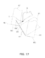
- FIG. 17 shows a method of calculating the shortest distance when a reckoned point is positioned in a gap area between a target area and a first non-target area in another embodiment.
- FIG. 1 is a perspective view of a hydraulic shovel 100 in which a display system is installed.
- the hydraulic shovel 100 has a main vehicle body 1 and a work machine 2 .
- the main vehicle body 1 is equivalent to the main body of the present invention.
- the main vehicle body 1 has an upper pivoting body 3 , a cab 4 , and a travel unit 5 .
- the upper pivoting body 3 includes devices, such as an engine, a hydraulic pump, and/or the like, which are not shown in the drawings.
- the cab 4 is installed on the front of the upper pivoting body 3 .
- a display input device 38 and an operating device 25 described below are disposed within the cab 4 (cf. FIG. 3 ).
- the travel unit 5 has tracks 5 a , 5 b , and the rotation of the tracks 5 a , 5 b causes the hydraulic shovel 100 to travel.
- the work machine 2 is attached to the front of the main vehicle body 1 , and has a boom 6 , an arm 7 , a bucket 8 , a boom cylinder 10 , an arm cylinder 11 , and a bucket cylinder 12 .
- the base end of the boom 6 is pivotally attached to the front of the main vehicle body 1 with a boom pin 13 disposed therebetween.
- the base end of the arm 7 is pivotally attached to the tip end of the boom 6 with an arm pin 14 disposed therebetween.
- the tip end of the arm 7 is pivotally attached to the bucket 8 with a bucket pin 15 disposed therebetween.
- FIG. 2 is a schematic illustration of the configuration of the hydraulic shovel 100 .
- FIG. 2( a ) is a side view of the hydraulic shovel 100
- FIG. 2( b ) is a rear view of the hydraulic shovel 100 .
- L 1 is the length of the boom 6 , i.e., the length from the boom pin 13 to the arm pin 14
- L 2 is the length of the arm 7 , i.e., the length from the arm pin 14 to the bucket pin 115
- L 3 is the length of the bucket 8 , i.e., the length from the bucket pin 15 to the blade edge of the bucket 8 .
- the boom cylinder 10 , arm cylinder 11 , and bucket cylinder 12 shown in FIG. 1 are hydraulic cylinders, each of which is driven by hydraulic pressure.
- the boom cylinder 10 drives the boom 6 .
- the arm cylinder 11 drives the arm 7 .
- the bucket cylinder 12 drives the bucket 8 .
- a proportional control valve 37 (cf, FIG. 3 ) is disposed between a hydraulic pump not shown in the drawings and the hydraulic cylinders, such as the boom cylinder 10 , arm cylinder 11 , bucket cylinder 12 , and the like.
- the proportional control valve 37 is controlled by a work machine controller 26 described below. Hence, the flow rate of hydraulic oil supplied to the hydraulic cylinders 10 - 12 is controlled. In this way, the movements of the hydraulic cylinders 10 - 12 are controlled.
- the boom 6 , arm 7 , and bucket 8 are provided with first through third stroke sensors 16 - 18 , respectively.
- the first stroke sensor 16 detects the stroke length of the boom cylinder 10 .
- a display controller 39 (cf. FIG. 3) calculates an angle of inclination ⁇ 1 of the boom 6 with respect to an axis Za (cf FIG. 7 ) of a main vehicle body coordinate system described below using the stroke length of the boom cylinder 10 detected by the first stroke sensor 16 .
- the second stroke sensor 17 detects the stroke length of the arm cylinder 11 .
- the display controller 39 calculates an angle of inclination ⁇ 2 of the arm 7 with respect to the boom 6 using the stroke length of the arm cylinder 11 detected by the second stroke sensor 17 .
- the third stroke sensor 18 detects the stroke length of the bucket cylinder 12 .
- the display controller 39 calculates an angle of inclination ⁇ 3 of the bucket 8 with respect to the arm 7 using the stroke length of the bucket cylinder 12 detected by the third stroke sensor 18 .
- the main vehicle body 1 is provided with a position detector unit 19 .
- the position detector unit 19 detects the current position of the hydraulic shovel 100 .
- the position detector unit 19 has two Real-Time-Kinematic Global Navigation Satellite System (RTK-GNSS) antennas 21 , 22 (hereafter, “GNSS antennas 21 , 22 ”), a three-dimensional position sensor 23 , and an inclination angle sensor 24 .
- the GNSS antennas 21 , 22 are disposed at a fixed interval along a Ya axis (cf. FIG. 7 ) of a main vehicle body coordinate system Xa-Ya-Za described below. Signals corresponding to GNSS radio waves received by the GNSS antennas 21 , 22 are inputted to the three-dimensional position sensor 23 .
- the three-dimensional position sensor 23 detects mounting positions P 1 , P 2 of the GNSS antennas 21 , 22 .
- the inclination angle sensor 24 detects an angle of inclination ⁇ 4 (hereafter, “roll angle ⁇ 4 ”) of the widthwise direction of the main vehicle body 1 with respect to the direction of gravity (a vertical line).
- “widthwise direction” refers to the widthwise direction of the bucket 8 , and is the same as the widthwise direction of the vehicle. However, if the work machine 2 is provided with a tilting bucket as described below, the widthwise direction of the bucket may not correspond to the vehicle widthwise direction.
- FIG. 3 is a block diagram of the configuration of a control system which the hydraulic shovel 100 comprises.
- the hydraulic shovel 100 comprises the operating device 25 , the work machine controller 26 , a work machine control device 27 , and a display system 28 .
- the operating device 25 has a work machine operating member 31 , a work machine operation detector unit 32 , a travel operating member 33 , and a travel operation detector unit 34 .
- the work machine operating member 31 is a member for allowing an operator to operate the work machine 2 , and is, for example, an operating lever.
- the work machine operation detector unit 32 detects the details of the operation inputted by using the work machine operating member 31 , and sends the details to the work machine controller 26 as a detection signal.
- the travel operating member 33 is a member for allowing an operator to operate the traveling of the hydraulic shovel 100 , and is, for example, an operating lever.
- the travel operation detector unit 34 detects the details of the operation inputted by using the travel operating member 33 , and sends the details to the work machine controller 26 as a detection signal.
- the work machine controller 26 has a storage unit 35 such as RAM or ROM, and a calculation unit 36 such as a CPU.
- the work machine controller 26 primarily controls the work machine 2 .
- the work machine controller 26 generates a control signal for causing the work machine 2 to act according to the operation of the work machine operating member 31 , and outputs the signal to the work machine con rot device 27 .
- the work machine control device 27 has the proportional control valve 37 , and the proportional control valve 37 is controlled based on the control signal from the work machine controller 26 . Hydraulic oil is drained from the proportional control valve 37 at a flow rate corresponding to the control signal from the work machine controller 26 , and is supplied to the hydraulic cylinders 10 - 12 .
- the hydraulic cylinders 10 to 12 are driven according to the hydraulic oil supplied from the proportional control valve 37 . This causes the work machine 2 to act.
- the display system 28 is a system for providing an operator with information for digging the ground within a work area to form a shape like that of a design surface described hereafter.
- the display system 28 comprises a display input device 28 and a display controller 39 along with the first through third stroke sensors 16 to 18 , the three-dimensional position sensor 23 , and the inclination angle sensor 24 described above.
- the display input device 38 has an input unit 41 like a touch panel, and a display unit 42 such as an LCD.
- the display input device 38 displays a guidance picture for providing information for digging operation. A variety of keys are shown in the guidance picture. An operator can execute the variety of functions of the display system 28 by touching the keys in the guidance picture. The guidance picture will be described in detail later.
- the display controller 39 executes the variety of functions of the display system 28 .
- the display controller 39 has a storage unit 43 such as RAM or ROM, and a calculation unit 44 such as a CPU.
- the storage unit 43 stores work machine data.
- the work machine data comprises the length L 1 of the boom 6 , the length L 2 of the arm 7 , and the length L 3 of the bucket 8 described above.
- the work machine data also comprises the minimum and maximum values for each of the angle of inclination ⁇ 1 of the boom 6 , the angle of inclination ⁇ 2 of the arm 7 , and the angle of inclination ⁇ 3 of the bucket 8 .
- the display controller 39 and the work machine controller 26 are capable of communicating with each other via wired or wireless communication means.
- Design land shape data is created in advance and stored in the storage unit 43 of the display controller 39 .
- the design land shape data is information pertaining to the three-dimensional shape and position of the design land shape.
- the design land shape indicates a target shape for the ground that is the work object.
- the display controller 39 displays a guidance picture on the display input device 38 based on data such as the design land shape data and the results detected by the various sensors described above.
- the design land shape includes a plurality of design surfaces 45 , each of which is represented using a triangular polygon. In FIG. 4 , only one of the plurality of design surfaces is labeled 45 , while labels for the other design surfaces are omitted.
- the target work object is one or a plurality of design surfaces among the design surfaces 45 .
- the operator selects one or a plurality of design surfaces among the design surfaces 45 as a target surface 70 .
- the display controller 39 causes the display input device 38 to display a guidance picture for informing the operator of the position of the target surface 70 .
- the guidance picture is a picture for showing the positional relationship between the target surface 70 and the blade edge of the bucket 8 , and for guiding the work machine 2 of the hydraulic shovel 100 so that the ground forming the work object takes on the same shape as the target surface 70 .
- the guidance picture includes a rough digging mode of a guidance picture (hereafter, “rough digging picture 53 ”), and a fine digging mode of a guidance picture (hereafter, “fine digging picture 54 ”).
- FIG. 5 illustrates the rough digging picture 53 .
- the rough digging picture 53 comprises an upper view 53 a showing the design land shape of the work area and the current position of the hydraulic shovel 100 , and a side view 53 b showing the positional relationship between the target surface 70 and the hydraulic shovel 100 .
- the upper view 53 a of the rough digging picture 53 represents the design land shape as viewed from above using a plurality of triangular polygons. More specifically, the upper view 53 a represents the design land shape using the pivoting plate of the hydraulic shovel 100 as a projected plane. Thus, the upper view 53 a is a view directly from above the hydraulic shovel 100 , and the design surface tilts when the hydraulic shovel 100 tilts.
- the target surface 70 selected from the plurality of design surfaces 45 as the target work object is displayed in a different color from the rest of the design surfaces 45 .
- current position of the hydraulic shovel 100 is displayed as an icon 61 of the hydraulic shovel as seen from above, but another symbol may be displayed to indicate the current position.
- the upper view 53 a comprises information for bringing the hydraulic shovel 100 directly face-to-face with the target surface 70 .
- the information for bringing the hydraulic shovel 100 directly face-to-face with the target surface 70 is displayed as a facing compass 73 .
- the facing compass 73 is an icon showing the direction directly facing the target surface 70 and the direction of the hydraulic shovel 100 to pivot in. The operator can find the degree to which the shovel faces the target surface 70 using the facing compass 73 .
- the side view 53 b of the rough digging picture 53 comprises an image showing the positional relationship between the target surface 70 and the blade edge of the bucket 8 , and distance information indicating the distance between the target surface 70 and the blade edge of the bucket 8 .
- the side view 53 b comprises a design surface line 74 , a target surface line 79 , and an icon 75 of the hydraulic shovel 100 as seen from the side.
- the design surface line 74 indicates a cross section of the design surfaces 45 apart from the target surface 70 .
- the target surface line 79 indicates a cross section of the target surface 70 . As shown in FIG.
- a design surface line 81 and a target surface line 8 are obtained by calculating an intersection 80 of the design surfaces 45 and a plane 77 passing through a current position of the blade edge P 3 of the bucket 8 .
- a method of calculating the current position of the blade edge P 3 of the bucket 8 will be described later.
- the target surface line 79 is displayed in a different color from the design surface line 74 .
- different types of line are used to represent the target surface line 79 and the design surface line 74 .
- the area closer to the ground than the target surface line 79 and the design surface line 74 and the area on the side closer to the air than these line segments are displayed in different colors.
- a dot pattern in the area closer to the ground than the target surface line 79 and the design surface line 74 represents the difference in color.
- the distance information indicating the distance between the target surface 70 and the blade edge of the bucket 8 comprises numerical value information 83 and graphic information 84 .
- the numerical value information 83 is a numerical value indicating the shortest distance between the blade edge of the bucket 8 and the target surface 70 .
- the graphic information 84 is information graphically indicating the distance between the blade edge of the bucket 8 and the target surface 70 .
- the graphic information 84 comprises index bars 84 a and an index mark 84 b indicating a position among positions of the index bars 84 a where the distance between the blade edge of the bucket 8 and the target surface 70 is equivalent to zero.
- the index bars 84 a are configured so as to illuminate according to the shortest distance between the tip of the bucket 8 and the target surface 70 . Displaying the graphic information 84 may be switched on/off through the operator's operation. The method of calculating the distance between the blade edge of the bucket 8 and the target surface 70 will be described in detail later.
- a picture change key 65 for switching between guidance pictures is displayed in the rough digging picture 53 .
- An operator can switch from the rough digging picture 53 to the fine digging picture 54 by operating the screen change key 65 .
- FIG. 6 illustrates the fine digging picture 54 .
- the fine digging picture 54 shows the positional relationship between the target surface 70 and the hydraulic shovel 100 in greater detail than the rough digging picture 53 .
- the fine digging picture 54 shows the positional relationship between the target surface 70 and the blade edge of the bucket 8 in greater detail than the rough digging picture 53 .
- the fine digging picture 54 has a head-on view 54 a showing the target surface 70 and the bucket 8 , and a side view 54 b showing the target surface 70 and the bucket 8 .
- the head-on view 54 a of the fine digging picture 54 comprises an icon 89 of the bucket 8 as seen head-on and a line 78 indicating a cross-section of the target surface 70 as seen head-on (hereafter, “target surface line 78 ”).
- the side view 54 b of the fine digging picture 54 comprises an icon 90 of the bucket 8 as seen from the side and the design surface line 74 .
- Both the head-on view 54 a and the side view 54 b of the fine digging picture 54 show information indicating the positional relationship between the target surface 70 and the bucket 8 .
- the information indicating the positional relationship between the target surface 70 and the bucket 8 on the head-on view 54 a comprises distance information 86 a and angle information 86 b .
- the distance information 86 a indicates the distance between the blade edge of the bucket 8 and the target surface 70 in the direction Za. As will be described later, this distance is the distance between the target surface 70 and the position closest to the target surface 70 among positions of the blade edge of the bucket 8 in the widthwise direction.
- a mark 86 c indicating the closest position is displayed overlapping the icon 89 of the head-on view of the bucket 8 .
- the angle information 86 b is information indicating the angle between the target surface 70 and bucket 8 . Specifically, the angle information 86 b is the angle between an imaginary line segment passing through the blade edge of the bucket 8 and the target surface line 78 .
- the information indicating the positional relationship between the target surface 70 and the bucket 8 in the side view 54 b comprises distance information 87 a and angle information 87 b .
- the distance information 87 a indicates the shortest distance between the target surface 70 and the blade edge of the bucket 8 , i.e., the distance between the target surface 70 and the tip of the bucket 8 in the direction of a line perpendicular to the target surface 70 .
- the angle information 87 b is information indicating the angle between the target surface 70 and the bucket 8 . Specifically, the angle information 87 b displayed in the side view 54 b is the angle between the bottom surface of the bucket 8 and the target surface line 79 .
- the fine digging picture 54 includes graphic information 88 graphically indicating the distance between the blade edge of the bucket 8 and the target surface 70 as described above.
- the graphic information 88 like the graphic information 84 of the rough digging picture 53 , has an index bar 88 a and an index mark 88 b.
- the relative positional relationships between the target surface lines 78 , 79 and the blade edge of the bucket 8 are shown in detail in the fine digging picture 54 .
- the operator can set the blade edge of the bucket 8 to move along the target surface lines 78 , 79 so that the current land shape takes on the same shape as the three-dimensional design land shape, which leads to easier operation of digging.
- a picture change key 65 is displayed in the fine digging picture 54 . An operator can switch from the fine digging picture 54 to the rough digging picture 53 by operating the screen change key 65 .
- the target surface line 79 is calculated based on the current position of the blade edge of the bucket 8 .
- the display controller 39 calculates the current position of the blade edge of the bucket 8 in a global coordinate system ⁇ X, Y, Z ⁇ based on the results detected by the three-dimensional position sensor 23 , first through third stroke sensors 16 - 18 , inclination sensor 24 , and the like. Specifically, the current position of the blade edge of the bucket S is obtained as follows.
- FIG. 7 a main vehicle body coordinate system ⁇ Xa, Ya, Za ⁇ whose point of origin is the mounting position P 1 of the GNSS antenna 21 described above is obtained.
- FIG. 7( a ) is a side view of the hydraulic shovel 100 .
- FIG. 7( b ) is a rear view of the hydraulic shovel 100 .
- the front-back direction of the hydraulic shovel 100 i.e., the Ya axis direction of the main vehicle body coordinate system, is inclined with respect to the Y axis direction of the global coordinate system.
- the coordinates of the boom pin 13 in the main vehicle body coordinate system are (0, Lb 1 , ⁇ Lb 2 ), and are stored in the storage unit 43 of the display controller 39 in advance.
- the three-dimensional position sensor 23 detects the mounting positions P 1 , P 2 of the GNSS antennas 21 , 22 .
- a unit vector for the Ya axis direction is calculated from the detected coordinate positions P 1 , P 2 according to the following formula (1).
- Ya ( P 1 ⁇ P 2)/
- Z′ is Obtained in the following formula (4).
- Z′ Z + ⁇ ( Ya ⁇ Z )/(( Z,Ya ) ⁇ 1) ⁇ ( Ya ⁇ Z ) (4)
- the main vehicle body coordinate system is rotated around the Ya axis by the roll angle ⁇ 4 , and is thus shown as in the following formula (6).
- the current angles of inclination ⁇ 1 , ⁇ 2 , ⁇ 3 of the boom 6 , arm 7 , and bucket 8 , respectively as described above are calculated from the results detected by the first through third stroke sensors 16 - 18 .
- yat Lb 1 +L 1 sin ⁇ 1 +L 2 sin( ⁇ 1+ ⁇ 2)+ L 3 sin( ⁇ 1+ ⁇ 2+ ⁇ 3)
- zat ⁇ Lb 2+ L 1 cos ⁇ 1+ L 2 cos( ⁇ 1+ ⁇ 2)+ L 3 cos( ⁇ 1+ ⁇ 2+ ⁇ 3) (9)
- the blade edge P 3 of the bucket 8 moves along the plane Ya-Za in the main vehicle body coordinate system.
- the display controller 39 calculates, on the basis of the current position of the blade edge of the bucket 8 calculated as described above and the design land shape data stored in the storage unit 43 , an intersection 80 of the three-dimensional design land shape and a Ya-Za plane 77 through which the blade edge P 3 of the bucket 8 passes.
- the display controller 39 displays the part of the intersection passing through the target surface 70 in the guidance picture as the target surface line 79 described above.
- the distance between the blade edge of the bucket 8 and the target surface 70 displayed in the guidance picture is the distance between the target surface 70 and the position closest to the target surface 70 among positions of the blade edge in the widthwise direction of the blade edge. Processes executed by the display controller 39 in order to calculate the distance between the blade edge of the bucket 8 and the target surface 70 will be described with referring to FIG. 8 .
- step S 1 the current position of the hydraulic shovel 100 is detected.
- the display controller 39 detects the current position of the main vehicle body 1 based on the detection signal from the three-dimensional position sensor 23 , as described above.
- step S 2 a plurality of reckoned points on the blade edge of the bucket 8 are set.
- the bucket 8 has a plurality of blades 8 a - 8 e . Therefore, an imaginary line segment LS 1 which passes through the tips of the plurality of blades 8 a - 8 e and which corresponds to the size of the bucket 8 in the widthwise direction of the bucket 8 is assumed, The imaginary line segment LS 1 is divided into four sub-segments whose lengths are equal, and the five points indicating the ends of the sub-segments are set as first through fifth reckoned points C 1 TO C 5 .
- the first through fifth reckoned points C 1 TO C 5 indicate a plurality of positions of the blade edge of the bucket 8 in the widthwise direction of the blade edge.
- the current positions of the first through fifth reckoned points C 1 TO C 5 are then calculated based on the current position of the hydraulic shovel 100 calculated in step S 1 .
- the current position of the central reckoned point C 3 is calculated according to the method of calculating the current position of the blade edge of the bucket 8 described above.
- the current positions of the other reckoned points C 1 , C 2 , C 4 , C 5 are calculated from the current position of the central reckoned point C 3 and the size of the bucket 8 in the widthwise direction of the bucket 8 .
- the size of the bucket 8 in the widthwise direction of the bucket 8 is stored in advance as the work machine data described above.
- steps S 3 through S 9 the distance between the design surface 45 and the reckoned point closest to the design surface 45 among the first through fifth reckoned points C 1 TO C 5 is calculated based on the positional information for the design surface 45 and the current positions of the first through fifth reckoned points C 1 TO C 5 .
- the specific processes are followings:
- step S 3 an intersection Mi of the design surface 45 and a Ya-Za plane passing through an i-th reckoned point Ci is calculated, where i is a variable, and the value of i for the i-th reckoned point Ci is set to 1 at the beginning of the flow shown in FIG. 8 .
- the intersection Mi of the design surface 45 and the Ya-Za plane passing through the i-th reckoned point Ci is calculated according to a method similar to the method of obtaining the intersection 80 as described above, which is shown in FIG. 4 . For example, let us assume that the blade edge of the bucket 8 is disposed over both a target surface 70 selected from the design surfaces 45 by an operator and unselected non-target surfaces 71 , 72 , as shown in FIG.
- the non-target surfaces 71 , 72 include a first non-target surface 71 and a second non-target surface 72 , and the target surface 70 is positioned between the first non-target surface 71 and the second non-target surface 72 .
- the intersection Mi of the design surface and the Ya-Za plane passing through the i-th reckoned point Ci comprises a target line MAi, a first non-target line MBi, and a second non-target line MCi.
- the target line MAi is the intersection of the target surface and the Ya-Za plane passing through the i-th reckoned point Ci, and is a straight line indicating the cross-section of the target surface 70 .
- the first non-target line MBi is the intersection of the first non-target surface 71 and the Ya-Za plane passing through the i-th reckoned point Ci, and is a straight line indicating the cross-section of the first non-target surface 71 .
- the second non-target line MCi is the intersection of the second non-target surface 72 and the Ya-Za plane passing through the i-th reckoned point Ci, and is a straight line indicating the cross-section of the second non-target surface 72 .
- step S 4 it is determined whether or not the i-th reckoned point Ci of the blade edge of the bucket 8 is positioned in the direction of a line perpendicular to the intersection Mi. For example, if the i-th reckoned point Ci is positioned in an area perpendicularly facing the target line MAi (hereafter, “target area A 1 ”), as shown in FIG. 11 , the i-th reckoned point Ci is determined to be positioned in the direction of a line perpendicular to the intersection Mi. If the i-th reckoned point Ci is positioned in an area perpendicularly facing the first nor target line MBi (hereafter, “first non-target area A 2 ”), as shown in FIG.
- the i-th reckoned point Ci of the blade edge of the bucket 8 is also determined to be positioned in the direction of a line perpendicular to the intersection Mi. However, if the i-th reckoned point Ci is positioned in a gap area between the target area A 1 and the first non-target area A 2 , as shown in FIG. 13 , the i-th reckoned point Ci of the blade edge of the bucket 8 is determined not to be positioned in the direction of a line perpendicular to the intersection Mi.
- step S 5 is subsequently processed.
- step S 5 the distances between the i-th reckoned point Ci and the straight lines MAi-MCi composing the intersection Mi are calculated.
- lines passing through the i-th reckoned point Ci which are perpendicular to the straight lines MAi-MCi composing the intersection Mi are calculated, and the distances between the straight lines MAi-MCi and the i-th reckoned point Ci are calculated. For example, if the i-th reckoned point Ci is positioned within the target area A 1 as shown in FIG.
- a tine passing through the i-th reckoned point Ci which is perpendicular to the target line MAi is calculated, and the shortest distance between the i-th reckoned point Ci and the target line MAi (hereafter, “target surface distance DAi”) is calculated.
- target surface distance DAi the shortest distance between the i-th reckoned point Ci and the target line MAi.
- the i-th reckoned point Ci is positioned within an area in which the target area A 1 overlaps with the area perpendicularly facing the second non-target line MCi (hereafter, “second non-target area A 3 ”), as shown in FIG. 14 and FIG. 15 .
- two perpendicular lines are calculated. Specifically, a line passing through the i-th reckoned point Ci which is perpendicular to the target line MAi and a line passing through the i-th reckoned point Ci which is perpendicular to the second non-target line MCi are calculated.
- the target surface distance DAi at the i-th reckoned point Ci and the shortest distance between the i-th reckoned point Ci and the second non-target line MCi (hereafter, “second non-target surface distance DCi”) are calculated.
- step S 6 is subsequently processed.
- a distance between an i-th reckoned point Ci of the blade edge of the bucket 8 and each of end points of the straight lines MAi-MCi is calculated for each of the straight lines MAi-MCi of the intersection Mi.
- provisional target surface distance DDi a distance between the i-th reckoned point Ci and an end point PAi of the target line MAi (hereafter, “provisional target surface distance DDi”) is calculated, as shown in FIG. 13 .
- step S 7 it is determined whether or not distance calculation for all the reckoned points C 1 to C 5 has been completed.
- five reckoned points C 1 to C 5 are set.
- the i value of the i-th reckoned point Ci is incremented by 1 in step S 8 , and the flow returns to step S 3 .
- the processes from step S 3 through step S 6 are then repeated, and step S 9 is subsequently processed once distance calculation for all the reckoned points C 1 to C 5 has been completed.
- step S 9 the shortest of the plurality of calculated distances is set as the “shortest distance”.
- the reckoned point closest to the design surface 45 among the plurality of reckoned points C 1 to C 5 on the blade edge of the bucket 8 is determined to be the closest position.
- the distance between the design surfaces 45 and the reckoned point corresponding to the closest position is set as the “shortest distance”.
- step S 10 it is determined whether or not the “shortest distance” is the value calculated for the target surface 70 . Specifically, it is determined whether or not the distance set as the “shortest distance” is that calculated for the target line MAi including the end point PAi. If the “shortest distance” is the value calculated for the target surface 70 , step S 11 is subsequently processed. If the “shortest distance” is determined not to be the value calculated for the target surface 70 , step S 12 is subsequently processed.
- step S 11 and step S 12 the “shortest distance” is displayed in the guidance picture. Specifically, in step S 11 , information indicating the “shortest distance” selected in step S 9 is displayed in the rough digging picture 53 and the fine digging picture 54 along with an image showing the positional relationship between the design surfaces 45 and the blade edge of the bucket 8 . Additionally, as described above, the mark 86 c indicating the position of the reckoned point corresponding to the closest position is displayed overlapping with the head-on view 54 a in the fine digging picture 54 .
- the appearance of the display of the information indicating the “shortest distance” in step S 11 will be referred to hereafter as the “normal display appearance.” Specifically, if the “shortest distance” is determined to be the value calculated for the target surface 70 in step S 10 , the “shortest distance” is displayed in the guidance picture with the normal display appearance.
- step S 12 the “shortest distance” is displayed in the guidance picture with specific characteristics.
- the information indicating the “shortest distance” is displayed with characteristics different from the normal display appearance in the rough digging picture 53 and the fine digging picture 54 .
- the visual elements of the text or graphics for the information indicating the “shortest distance,” such as color or size, are different from the normal display appearance.
- the “shortest distance” is the value calculated for the first non-target surface 71 or the second non-target surface 72
- the “shortest distance” is displayed in the guidance picture with specific characteristics.
- the “shortest distance” is calculated and displayed in the guidance picture.
- a specific example of the calculation of the shortest distance will be shown below.
- the target surface distance DAi is calculated for each of the first through fifth reckoned points C 1 TO C 5 .
- the shortest of the five target surface distances DAi is selected as the “shortest distance”.
- the target surface distance DAi for the reckoned point closest to the target surface 70 is set as the “shortest distance”.
- the “shortest distance” is then displayed in the guidance picture with the normal display appearance.
- the first non-target surface distance DBi is calculated for each of the first through fifth reckoned points C 1 TO C 5 .
- the shortest of the five first non-target surface distances DBi is selected as the “shortest distance”.
- the first non-target surface distance DBi for the reckoned point closest to the first non-target surface 71 among the first through fifth reckoned points C 1 TO C 5 is set as the “shortest distance”. The “shortest distance” is then displayed in the guidance picture with specific characteristics.
- the provisional target surface distance DDi is calculated for each of the first through fifth reckoned points C 1 TO C 5 .
- the shortest of the five provisional target surface distances DDi is selected as the “shortest distance”.
- the provisional target surface distance DDi for the reckoned point closest to the outer boundary of the target surface 70 among the first through fifth reckoned points C 1 TO C 5 is set as the “shortest distance”. The “shortest distance” is then displayed in the guidance picture with the normal display appearance.
- the shortest of target surface distance DAi and provisional target surface distance DDi for the first through fifth reckoned points C 1 TO C 5 is selected as the “shortest distance”. The “shortest distance” is then displayed in the guidance picture with the normal display appearance.
- the shortest of target surface distance DAi and second non-target surface distance DCi for the first through fifth reckoned points C 1 TO C 5 is set as the “shortest distance”.
- the second non-target surface 72 is closer to the blade edge of the bucket 8 than the target surface 70
- the second non-target surface distance DCi fir the reckoned point positioned closest to the second non-target surface 72 is displayed in the guidance picture with specific characteristics.
- the target surface distance DAi for the reckoned point positioned closest to the target surface 70 is displayed in the guidance picture with the normal display appearance.
- the first through fifth reckoned points C 1 TO C 5 are positioned in the areas shown in FIG. 11 through HG 15 .
- the first reckoned point C 1 is positioned in the first non-target area A 2 shown in FIG. 12 .
- the second reckoned point C 2 is positioned in the gap area shown in FIG. 13 .
- the third reckoned point C 3 is positioned in the target area A 1 shown in FIG. 11 .
- the fourth reckoned point C 4 is positioned in the area in which the target area A 1 overlaps with the second non-target area A 3 as shown in FIG. 14 .
- the fifth reckoned point C 5 is positioned in the area in which the target area A 1 overlaps with the second non-target area A 3 as shown in FIG. 15 .
- the first non-target surface distance DBi shown in FIG. 12 is calculated for the first reckoned point C 1 .
- the provisional target surface distance DDi shown in FIG. 13 is calculated for the second reckoned point C 2 .
- the target surface distance DAi shown in FIG. 11 is calculated for the third reckoned point C 3 .
- the target surface distance DAi shown in FIG. 14 is calculated for the fourth reckoned point C 4 .
- the second non-target surface distance DCi shown in FIG. 15 is calculated for the fifth reckoned point C 5 .
- the shortest of the first non-target surface distance DBi for the first reckoned point C 1 , the provisional target surface distance DDi for the second reckoned point C 2 , the target surface distance DAi for the third reckoned point C 3 , the target surface distance DAi for the fourth reckoned point C 4 , and the second non-target surface distance DCi for the fifth reckoned point C 5 is then selected as the “shortest distance”.
- the information indicating the “shortest distance” is shown in the guidance picture with the normal display appearance.
- the information indicating the “shortest distance” is displayed in the guidance picture with specific characteristics.
- the hydraulic shovel display system 28 according to the present embodiment has the following characteristics.
- the display controller 39 calculates the distance between the design surface 45 and the position closest to the design surface 45 among the first reckoned point C 1 through the fifth reckoned point C 5 on the blade edge of the bucket 8 as the “shortest distance”, and displays distance information indicating the “shortest distance” in the guidance picture.
- the mark 86 c indicating the position closest to the design surfaces 45 is shown in the head-on view of the bucket 8 composing the fine digging picture 54 .
- an operator can easily ascertain the position closest to the design surface 45 in the head-on view of the bucket 8 . This allows the operator to perform more precise digging operation.
- the distance from the closest position to the non-target surface is calculated as the shortest distance
- information indicating the shortest distance is displayed with characteristics different from the normal display appearance.
- the distance from the outer boundary of the target surface 70 is calculated. Accordingly, an operator can easily ascertain, when the blade edge of the bucket 8 is out of an area in which the blade edge faces the target surface 70 , how far the blade edge of the bucket 8 is from the target surface 70 .
- the shortest of the distances from the reckoned points is selected as the shortest distance.
- distances D 1 to D 5 between each of the reckoned points C 1 to C 5 and the design surface 45 in the Ya-Za plane passing through each of the reckoned points C 1 to C 5 are calculated.
- an operator can easily ascertain the shortest distance in a direction parallel to the Ya-Za plane.
- the operator When the operator operates the work machine 2 , the operator normally moves the bucket 8 in a direction parallel to the Ya-Za plane.
- having the abovementioned distance-indicating information displayed in the guidance picture enables the operator to precisely ascertain the distance between the blade edge of the bucket 8 and the design surface 45 when operating the work machine 2 .
- the area closer to the ground than the design surface line 74 and the target surface line 79 and the area closer to the air than these line segments are shown in different colors.
- the display controller 39 may be executed by a computer disposed outside the hydraulic shovel 100 .
- the target work object is not limited to the plane described above, but may be a point, line, or three-dimensional shape.
- the input unit 41 of the display input device 38 is not limited to a touch panel, but may also comprise an operating member such as a hard key or a switch.
- an automatic digging mode may be additionally provided.
- the target surface line 79 described above is a target movement path along which the blade edge of the bucket 8 is to be moved.
- the display controller 39 outputs a control signal for automatically moving the blade edge of the bucket 8 along the target movement path to the work machine control device 27 .
- the work machine 2 automatically executes digging.
- the work machine 2 has a boom 6 , an arm 7 , and a bucket 8 , but the configuration of the work machine 2 is not limited thereto, and may have at least a bucket 8 .
- the angles of inclination of the boom 6 , arm 7 , and bucket 8 are detected by the first through third stroke sensors 16 to 18 , but the means for detecting the angles of inclination is not limited thereto.
- an angle sensor for detecting the angles of inclination of the boom 6 , arm 7 , and bucket 8 may be provided.
- a tilting bucket comprises a bucket tilting cylinder and is a bucket that can shape and level an inclined surface or fiat ground to a desired shape by tilting to the left or right even when the hydraulic shovel is positioned on the inclined surface, and that can perform compaction work using a bottom plate.
- distances D 1 to D 5 between each of the reckoned points C 1 to C 5 and the design surface 45 in the Ya-Za plane passing through each of the reckoned points C 1 to C 5 are calculated.
- the shortest distance of the distances between the reckoned points C 1 to C 5 and the design surface 45 may be calculated regardless of the direction.
- the shortest distance D 5 ′ to the design surface 45 in any direction may be calculated for the reckoned point C 5 .
- an operator can easily ascertain the shortest distance between the design surface 45 and the position closest to the design surface 45 regardless of the direction in which the work machine 2 is being operated.
- the bucket 8 may move not only in the drive direction of the work machine 2 , but also in the widthwise direction of the work machine 2 .
- the upper pivoting body 3 pivots, the bucket 8 moves in the widthwise direction.
- the distance between the i-th reckoned point Ci and the end point PAi indicating the outer boundary of the target surface 70 is calculated.
- the distance between the i-th reckoned point Ci and the extended plane of the target surface 70 may be calculated.
- the distance between the i-th reckoned point Ci and the extended line MAi′ of the target line MAi may be calculated as the provisional target surface distance DDi.
- the target surface 70 can easily be shaped by operating the blade edge of the bucket 8 parallel to the target surface 70 from a position away from the target surface 70 (for example, a position on the extended plane of the target surface 70 ). It is thus possible, shaping after positioning the blade edge at the top of the slope prevents collapse of earth above the top of the slope, or neat shaping from being impeded by the shock of the work machine 2 when it begins to act.
- the illustrated embodiment has an advantageous effect of enabling precise digging operation, and is effective as a display system in a hydraulic shovel and a control method therefor.
Landscapes
- Engineering & Computer Science (AREA)
- Mining & Mineral Resources (AREA)
- Civil Engineering (AREA)
- General Engineering & Computer Science (AREA)
- Structural Engineering (AREA)
- Component Parts Of Construction Machinery (AREA)
- Operation Control Of Excavators (AREA)
Applications Claiming Priority (3)
| Application Number | Priority Date | Filing Date | Title |
|---|---|---|---|
| JP2011-036197 | 2011-02-22 | ||
| JP2011036197A JP5054832B2 (ja) | 2011-02-22 | 2011-02-22 | 油圧ショベルの表示システム及びその制御方法 |
| PCT/JP2012/052829 WO2012114869A1 (ja) | 2011-02-22 | 2012-02-08 | 油圧ショベルの表示システム及びその制御方法 |
Publications (2)
| Publication Number | Publication Date |
|---|---|
| US20130158787A1 US20130158787A1 (en) | 2013-06-20 |
| US8942895B2 true US8942895B2 (en) | 2015-01-27 |
Family
ID=46720654
Family Applications (1)
| Application Number | Title | Priority Date | Filing Date |
|---|---|---|---|
| US13/819,456 Active US8942895B2 (en) | 2011-02-22 | 2012-02-08 | Display system of hydraulic shovel, and control method therefor |
Country Status (6)
| Country | Link |
|---|---|
| US (1) | US8942895B2 (ja) |
| JP (1) | JP5054832B2 (ja) |
| KR (1) | KR101411454B1 (ja) |
| CN (1) | CN103080437B (ja) |
| DE (1) | DE112012000106B4 (ja) |
| WO (1) | WO2012114869A1 (ja) |
Cited By (7)
| Publication number | Priority date | Publication date | Assignee | Title |
|---|---|---|---|---|
| US20160201298A1 (en) * | 2015-01-08 | 2016-07-14 | Caterpillar Inc. | Systems and Methods for Constrained Dozing |
| US9493929B2 (en) | 2012-11-19 | 2016-11-15 | Komatsu Ltd. | Display system of excavating machine and excavating machine |
| US10280597B2 (en) * | 2015-03-27 | 2019-05-07 | Sumitomo(S.H.I)Construction Machinery Co., Ltd. | Shovel |
| US20210047805A1 (en) * | 2018-03-15 | 2021-02-18 | Hitachi Construction Machinery Co., Ltd. | Construction machine |
| US11168466B2 (en) * | 2017-03-31 | 2021-11-09 | Sumitomo(S.H.I) Construction Machinery Co., Ltd. | Shovel, display device of shovel, and method of displaying image for shovel |
| US20220268000A1 (en) * | 2021-02-25 | 2022-08-25 | Hyundai Doosan Infracore Co., Ltd. | Machine guidance program and excavator using the same |
| US11613873B2 (en) | 2017-03-07 | 2023-03-28 | Sumitomo Heavy Industries, Ltd. | Shovel and work support system for construction machine |
Families Citing this family (39)
| Publication number | Priority date | Publication date | Assignee | Title |
|---|---|---|---|---|
| AU2012202213B2 (en) * | 2011-04-14 | 2014-11-27 | Joy Global Surface Mining Inc | Swing automation for rope shovel |
| US8914199B2 (en) | 2012-10-05 | 2014-12-16 | Komatsu Ltd. | Excavating machine display system and excavating machine |
| US8965642B2 (en) * | 2012-10-05 | 2015-02-24 | Komatsu Ltd. | Display system of excavating machine and excavating machine |
| JP5426742B1 (ja) * | 2012-10-05 | 2014-02-26 | 株式会社小松製作所 | 掘削機械の表示システム及び掘削機械 |
| US9043098B2 (en) | 2012-10-05 | 2015-05-26 | Komatsu Ltd. | Display system of excavating machine and excavating machine |
| JP5426743B1 (ja) * | 2012-10-05 | 2014-02-26 | 株式会社小松製作所 | 掘削機械の表示システム及び掘削機械 |
| CN103917717B (zh) | 2012-10-19 | 2016-03-23 | 株式会社小松制作所 | 液压挖掘机的挖掘控制系统 |
| JP6287488B2 (ja) * | 2014-03-31 | 2018-03-07 | 株式会社Jvcケンウッド | 対象物表示装置 |
| US9458598B2 (en) * | 2014-04-24 | 2016-10-04 | Komatsu Ltd. | Work vehicle |
| US9322149B2 (en) * | 2014-04-24 | 2016-04-26 | Komatsu Ltd. | Work vehicle |
| CN105636658B (zh) * | 2014-05-14 | 2018-03-23 | 株式会社小松制作所 | 液压挖掘机的校正系统以及校正方法 |
| CN105307739B (zh) * | 2014-05-15 | 2017-09-29 | 株式会社小松制作所 | 挖掘机械的显示系统、挖掘机械以及挖掘机械的显示方法 |
| JP6106129B2 (ja) * | 2014-06-13 | 2017-03-29 | 日立建機株式会社 | 建設機械の掘削制御装置 |
| US10161111B2 (en) | 2014-09-09 | 2018-12-25 | Komatsu Ltd. | Display system of excavation machine, excavation machine, and image display method |
| CN106715803B (zh) * | 2014-09-18 | 2020-09-01 | 住友建机株式会社 | 挖土机 |
| JP6297468B2 (ja) * | 2014-10-28 | 2018-03-20 | 住友建機株式会社 | ショベル |
| WO2016148242A1 (ja) * | 2015-03-19 | 2016-09-22 | 住友建機株式会社 | ショベル |
| JP6480830B2 (ja) * | 2015-08-24 | 2019-03-13 | 株式会社小松製作所 | ホイールローダの制御システム、その制御方法およびホイールローダの制御方法 |
| JP6620011B2 (ja) | 2015-12-25 | 2019-12-11 | 株式会社小松製作所 | 作業車両および表示制御方法 |
| JP6611205B2 (ja) | 2015-12-28 | 2019-11-27 | 住友建機株式会社 | ショベル及びショベルの表示装置 |
| CN108884668B (zh) * | 2016-03-30 | 2022-06-07 | 住友建机株式会社 | 挖土机 |
| JP6506205B2 (ja) * | 2016-03-31 | 2019-04-24 | 日立建機株式会社 | 建設機械 |
| JP6564739B2 (ja) * | 2016-06-30 | 2019-08-21 | 日立建機株式会社 | 作業機械 |
| JP6633464B2 (ja) * | 2016-07-06 | 2020-01-22 | 日立建機株式会社 | 作業機械 |
| JP7156775B2 (ja) | 2016-07-26 | 2022-10-19 | 株式会社小松製作所 | 作業車両の制御システム、制御方法、及び作業車両 |
| JP6934286B2 (ja) * | 2016-07-26 | 2021-09-15 | 株式会社小松製作所 | 作業車両の制御システム、制御方法、及び作業車両 |
| US10794046B2 (en) * | 2016-09-16 | 2020-10-06 | Hitachi Construction Machinery Co., Ltd. | Work machine |
| JP6718399B2 (ja) * | 2017-02-21 | 2020-07-08 | 日立建機株式会社 | 作業機械 |
| KR102455257B1 (ko) * | 2017-03-07 | 2022-10-14 | 스미토모 겐키 가부시키가이샤 | 쇼벨 |
| JP6872945B2 (ja) | 2017-03-27 | 2021-05-19 | 日立建機株式会社 | 建設機械 |
| CN110446816B (zh) * | 2017-08-09 | 2023-01-20 | 住友建机株式会社 | 挖土机、挖土机的显示装置及挖土机的显示方法 |
| JP6675809B2 (ja) * | 2018-04-25 | 2020-04-08 | 住友重機械工業株式会社 | ショベル支援装置 |
| JP7097022B2 (ja) * | 2018-08-31 | 2022-07-07 | コベルコ建機株式会社 | 建設機械 |
| JP7396875B2 (ja) * | 2019-11-27 | 2023-12-12 | 株式会社小松製作所 | 作業機械の制御システム、作業機械、および作業機械の制御方法 |
| KR20220010795A (ko) * | 2020-07-20 | 2022-01-27 | 현대두산인프라코어(주) | 굴삭기 및 이의 제어 방법 |
| JP7131779B2 (ja) * | 2020-10-08 | 2022-09-06 | 株式会社小松製作所 | 作業機械の画像表示システム、作業機械の遠隔操作システム、作業機械、及び作業機械の画像表示方法 |
| WO2022230417A1 (ja) | 2021-04-28 | 2022-11-03 | 日立建機株式会社 | 作業機械 |
| CN113343324B (zh) * | 2021-06-09 | 2023-03-28 | 东莞市友杰电子有限公司 | 液压式机械产品外形分析系统 |
| WO2023188319A1 (ja) * | 2022-03-31 | 2023-10-05 | 日立建機株式会社 | 油圧ショベルの表示システム |
Citations (6)
| Publication number | Priority date | Publication date | Assignee | Title |
|---|---|---|---|---|
| JP2001098585A (ja) | 1999-10-01 | 2001-04-10 | Komatsu Ltd | 建設機械の掘削作業ガイダンス装置および掘削制御装置 |
| US20040020083A1 (en) * | 2002-07-29 | 2004-02-05 | Staub Michael David | Method and apparatus for determining machine location |
| JP2004068433A (ja) | 2002-08-07 | 2004-03-04 | Hitachi Constr Mach Co Ltd | 掘削機械の表示システム及びそのプログラム |
| WO2004027164A1 (ja) | 2002-09-17 | 2004-04-01 | Hitachi Construction Machinery Co., Ltd. | 建設機械の掘削作業教示装置 |
| JP2006214246A (ja) | 2005-02-07 | 2006-08-17 | Aoki Asunaro Kensetsu Kk | 作業機の施工支援システム |
| US20110178677A1 (en) * | 2010-01-20 | 2011-07-21 | Caterpillar Trimble Control Technologies Llc | Machine control and guidance system incorporating a portable digital media device |
Family Cites Families (1)
| Publication number | Priority date | Publication date | Assignee | Title |
|---|---|---|---|---|
| JP4311577B2 (ja) * | 2003-09-02 | 2009-08-12 | 株式会社小松製作所 | 施工目標指示装置 |
-
2011
- 2011-02-22 JP JP2011036197A patent/JP5054832B2/ja active Active
-
2012
- 2012-02-08 KR KR1020137004021A patent/KR101411454B1/ko active IP Right Grant
- 2012-02-08 DE DE112012000106.0T patent/DE112012000106B4/de active Active
- 2012-02-08 WO PCT/JP2012/052829 patent/WO2012114869A1/ja active Application Filing
- 2012-02-08 US US13/819,456 patent/US8942895B2/en active Active
- 2012-02-08 CN CN201280002725.3A patent/CN103080437B/zh active Active
Patent Citations (7)
| Publication number | Priority date | Publication date | Assignee | Title |
|---|---|---|---|---|
| JP2001098585A (ja) | 1999-10-01 | 2001-04-10 | Komatsu Ltd | 建設機械の掘削作業ガイダンス装置および掘削制御装置 |
| US20040020083A1 (en) * | 2002-07-29 | 2004-02-05 | Staub Michael David | Method and apparatus for determining machine location |
| JP2004068433A (ja) | 2002-08-07 | 2004-03-04 | Hitachi Constr Mach Co Ltd | 掘削機械の表示システム及びそのプログラム |
| WO2004027164A1 (ja) | 2002-09-17 | 2004-04-01 | Hitachi Construction Machinery Co., Ltd. | 建設機械の掘削作業教示装置 |
| US20050027420A1 (en) * | 2002-09-17 | 2005-02-03 | Kazuo Fujishima | Excavation teaching apparatus for construction machine |
| JP2006214246A (ja) | 2005-02-07 | 2006-08-17 | Aoki Asunaro Kensetsu Kk | 作業機の施工支援システム |
| US20110178677A1 (en) * | 2010-01-20 | 2011-07-21 | Caterpillar Trimble Control Technologies Llc | Machine control and guidance system incorporating a portable digital media device |
Non-Patent Citations (1)
| Title |
|---|
| International Search Report of corresponding PCT Application No. PCT/JP2012/052829. |
Cited By (8)
| Publication number | Priority date | Publication date | Assignee | Title |
|---|---|---|---|---|
| US9493929B2 (en) | 2012-11-19 | 2016-11-15 | Komatsu Ltd. | Display system of excavating machine and excavating machine |
| US20160201298A1 (en) * | 2015-01-08 | 2016-07-14 | Caterpillar Inc. | Systems and Methods for Constrained Dozing |
| US10280597B2 (en) * | 2015-03-27 | 2019-05-07 | Sumitomo(S.H.I)Construction Machinery Co., Ltd. | Shovel |
| US11613873B2 (en) | 2017-03-07 | 2023-03-28 | Sumitomo Heavy Industries, Ltd. | Shovel and work support system for construction machine |
| US11168466B2 (en) * | 2017-03-31 | 2021-11-09 | Sumitomo(S.H.I) Construction Machinery Co., Ltd. | Shovel, display device of shovel, and method of displaying image for shovel |
| US20210047805A1 (en) * | 2018-03-15 | 2021-02-18 | Hitachi Construction Machinery Co., Ltd. | Construction machine |
| US11505923B2 (en) * | 2018-03-15 | 2022-11-22 | Hitachi Construction Machinery Co., Ltd. | Construction machine |
| US20220268000A1 (en) * | 2021-02-25 | 2022-08-25 | Hyundai Doosan Infracore Co., Ltd. | Machine guidance program and excavator using the same |
Also Published As
| Publication number | Publication date |
|---|---|
| CN103080437B (zh) | 2014-12-10 |
| WO2012114869A1 (ja) | 2012-08-30 |
| JP5054832B2 (ja) | 2012-10-24 |
| JP2012172425A (ja) | 2012-09-10 |
| DE112012000106B4 (de) | 2014-12-31 |
| US20130158787A1 (en) | 2013-06-20 |
| KR101411454B1 (ko) | 2014-06-24 |
| CN103080437A (zh) | 2013-05-01 |
| DE112012000106T5 (de) | 2013-07-04 |
| KR20130038387A (ko) | 2013-04-17 |
Similar Documents
| Publication | Publication Date | Title |
|---|---|---|
| US8942895B2 (en) | Display system of hydraulic shovel, and control method therefor | |
| US10267020B2 (en) | Display system in an excavator and method for controlling same | |
| US8903604B2 (en) | Display system in hydraulic shovel and control method therefor | |
| US8498806B2 (en) | Hydraulic shovel positional guidance system and method of controlling same | |
| US8886416B2 (en) | Hydraulic shovel operability range display device and method for controlling same | |
| JP5781668B2 (ja) | 油圧ショベルの表示システム | |
| US8965642B2 (en) | Display system of excavating machine and excavating machine | |
| US9493929B2 (en) | Display system of excavating machine and excavating machine | |
| JP5555190B2 (ja) | 油圧ショベルの表示システム及びその制御方法 | |
| US8914199B2 (en) | Excavating machine display system and excavating machine | |
| KR101513382B1 (ko) | 굴삭 기계의 표시 시스템 및 굴삭 기계 | |
| KR20150022922A (ko) | 굴삭 기계의 표시 시스템, 굴삭 기계 및 굴삭 기계의 표시용 컴퓨터 프로그램 | |
| JP5480941B2 (ja) | 掘削機械の表示システム及びその制御方法。 |
Legal Events
| Date | Code | Title | Description |
|---|---|---|---|
| AS | Assignment |
Owner name: KOMATSU LTD., JAPAN Free format text: ASSIGNMENT OF ASSIGNORS INTEREST;ASSIGNORS:NOMURA, AZUMI;KURIHARA, TAKASHI;FUJITA, ETSUO;AND OTHERS;SIGNING DATES FROM 20121225 TO 20130109;REEL/FRAME:029886/0115 |
|
| STCF | Information on status: patent grant |
Free format text: PATENTED CASE |
|
| MAFP | Maintenance fee payment |
Free format text: PAYMENT OF MAINTENANCE FEE, 4TH YEAR, LARGE ENTITY (ORIGINAL EVENT CODE: M1551) Year of fee payment: 4 |
|
| MAFP | Maintenance fee payment |
Free format text: PAYMENT OF MAINTENANCE FEE, 8TH YEAR, LARGE ENTITY (ORIGINAL EVENT CODE: M1552); ENTITY STATUS OF PATENT OWNER: LARGE ENTITY Year of fee payment: 8 |