US8915269B2 - Method and filling system for filling containers with a filling material composed of at least two components in a volume-and/or amount-controlled manner - Google Patents
Method and filling system for filling containers with a filling material composed of at least two components in a volume-and/or amount-controlled manner Download PDFInfo
- Publication number
- US8915269B2 US8915269B2 US13/513,882 US201013513882A US8915269B2 US 8915269 B2 US8915269 B2 US 8915269B2 US 201013513882 A US201013513882 A US 201013513882A US 8915269 B2 US8915269 B2 US 8915269B2
- Authority
- US
- United States
- Prior art keywords
- component
- filling
- volume
- chamber
- flow rate
- Prior art date
- Legal status (The legal status is an assumption and is not a legal conclusion. Google has not performed a legal analysis and makes no representation as to the accuracy of the status listed.)
- Expired - Fee Related
Links
Images


Classifications
-
- B—PERFORMING OPERATIONS; TRANSPORTING
- B67—OPENING, CLOSING OR CLEANING BOTTLES, JARS OR SIMILAR CONTAINERS; LIQUID HANDLING
- B67C—CLEANING, FILLING WITH LIQUIDS OR SEMILIQUIDS, OR EMPTYING, OF BOTTLES, JARS, CANS, CASKS, BARRELS, OR SIMILAR CONTAINERS, NOT OTHERWISE PROVIDED FOR; FUNNELS
- B67C3/00—Bottling liquids or semiliquids; Filling jars or cans with liquids or semiliquids using bottling or like apparatus; Filling casks or barrels with liquids or semiliquids
- B67C3/02—Bottling liquids or semiliquids; Filling jars or cans with liquids or semiliquids using bottling or like apparatus
- B67C3/20—Bottling liquids or semiliquids; Filling jars or cans with liquids or semiliquids using bottling or like apparatus with provision for metering the liquids to be introduced, e.g. when adding syrups
-
- B—PERFORMING OPERATIONS; TRANSPORTING
- B67—OPENING, CLOSING OR CLEANING BOTTLES, JARS OR SIMILAR CONTAINERS; LIQUID HANDLING
- B67C—CLEANING, FILLING WITH LIQUIDS OR SEMILIQUIDS, OR EMPTYING, OF BOTTLES, JARS, CANS, CASKS, BARRELS, OR SIMILAR CONTAINERS, NOT OTHERWISE PROVIDED FOR; FUNNELS
- B67C3/00—Bottling liquids or semiliquids; Filling jars or cans with liquids or semiliquids using bottling or like apparatus; Filling casks or barrels with liquids or semiliquids
- B67C3/02—Bottling liquids or semiliquids; Filling jars or cans with liquids or semiliquids using bottling or like apparatus
- B67C3/023—Filling multiple liquids in a container
-
- B—PERFORMING OPERATIONS; TRANSPORTING
- B67—OPENING, CLOSING OR CLEANING BOTTLES, JARS OR SIMILAR CONTAINERS; LIQUID HANDLING
- B67C—CLEANING, FILLING WITH LIQUIDS OR SEMILIQUIDS, OR EMPTYING, OF BOTTLES, JARS, CANS, CASKS, BARRELS, OR SIMILAR CONTAINERS, NOT OTHERWISE PROVIDED FOR; FUNNELS
- B67C3/00—Bottling liquids or semiliquids; Filling jars or cans with liquids or semiliquids using bottling or like apparatus; Filling casks or barrels with liquids or semiliquids
- B67C3/02—Bottling liquids or semiliquids; Filling jars or cans with liquids or semiliquids using bottling or like apparatus
- B67C3/20—Bottling liquids or semiliquids; Filling jars or cans with liquids or semiliquids using bottling or like apparatus with provision for metering the liquids to be introduced, e.g. when adding syrups
- B67C3/206—Bottling liquids or semiliquids; Filling jars or cans with liquids or semiliquids using bottling or like apparatus with provision for metering the liquids to be introduced, e.g. when adding syrups using arrangements of cylinders and pistons
Definitions
- This disclosure relates to filling containers with a filling material.
- Methods and filling systems are known for filling containers with a liquid filling material composed of at least two components that are introduced separately into the respective container in a volume-controlled and/or amount-controlled manner, in particular also for the bottling of fruit juices in which case one component is a homogenous liquid and a further component exhibits, for example, a high proportion of solids, e.g. fruit pulp and/or fruit fiber.
- Volume-measuring or amount-measuring devices or flowmeters in particular contactlessly operating electronic flowmeters, for example magnetically inductive flowmeters, which may be very suitable for electrically conductive liquid and homogenous components and provide exact measurement signals depending on the particular volumetric flow rate but which are not or only partly suitable for non-homogenous components and in particular components containing a high concentration of solids, are often used for volume-controlled or amount-controlled filling.
- electronic flowmeters for example magnetically inductive flowmeters
- magnetically inductive flowmeters which may be very suitable for electrically conductive liquid and homogenous components and provide exact measurement signals depending on the particular volumetric flow rate but which are not or only partly suitable for non-homogenous components and in particular components containing a high concentration of solids, are often used for volume-controlled or amount-controlled filling.
- each of the components that are to be sequentially introduced into the respective container be provided with its own liquid path connected to a storage tank for the component concerned, and that a flowmeter be disposed in only one of the liquid paths, namely in the liquid path for a first liquid and homogenous component, said flowmeter directly measuring the amount of that component introduced into the respective container during filling and indirectly measuring the amount of a second component introduced into the respective container.
- the object of the invention is to provide a method and apparatus that avoids the foregoing disadvantages. Suitable methods and apparatuses are recited in the attached claims.
- the amount or volume of the at least one second component is also measured indirectly by measuring or capturing the first component's volumetric flow rate which results from the volumetric flow rate of the at least one second component, the volumetric flow rate of the least one second component being the volumetric flow rate of this component directly flowing to the respective container.
- the flow through the flowmeter used for the measurement is in one and the same direction, this also being the direction of flow in which the first component flows through the first liquid channel when introduced into the respective container.
- At least one first chamber is associated with the first liquid channel for the first component and at least one second chamber with variable volume is associated with the second liquid channel for the second component, and that when the second component is introduced into the respective container, the volume of the at least one second chamber associated with the second component is reduced, starting from an initial volume and accompanied by an increase in the volume of the at least one first chamber associated with the first component.
- the amount (volume) of the first component measured by the flowmeter is equal to the amount (volume) of the second component introduced into the container. If the volume-controlled or amount-controlled introduction of several “second” components into each container is necessary, then the above described indirect measurement of the amounts (volumes) of the “second” components is carried out with a time delay.
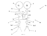
- FIGS. 1 and 2 each schematically show a filling position of a filling systems for filling containers with two components K 1 and K 2 of a filling material.
- FIG. 1 shows a schematic function representation of part of a filling system 1 , for example of a rotary filling machine for filling containers 2 with the different components K 1 and K 2 .
- these components are introduced into the respective container 2 in an amount-controlled and/or volume-controlled manner in a given mix ratio or each with a given nominal volume, and also in such a way that each container 2 contains a given total amount of the mixed product, for example of a drink or fruit juice.
- Component K 1 is for example a liquid homogenous or essentially homogenous component, for example fruit juice.
- Component K 2 is for example a non-homogenous component which with a reduced proportion of liquid contains a high proportion of solids, e.g. in the fruit pulp and/or fruit fibres etc.
- Filling system 1 comprises a plurality of filling positions, each with a filling element 3 , which in the case of rotary filling machines is provided together with further filling elements on the periphery of a rotor driven to rotate about a vertical machine axis in the manner known to the person skilled in the art.
- Filling element 3 is configured with a valve V 1 (liquid valve) for the controlled starting and stopping of the filling process.
- V 1 liquid valve
- the respective container 2 is disposed under filling element 3 or under a delivery opening there located, and in the depiction of FIG. 1 is at a distance away from filling element 3 for open jet filling.
- tank 4 contains component K 1 with a pressure P 1
- tank 5 contains component K 2 with a pressure P 2 .
- P 3 the filling pressure
- the pressure in tanks 4 and 5 is set so that pressure P 1 is less than pressure P 2 but greater than pressure P 3 , hence P 3 ⁇ P 1 ⁇ P 2 .
- Filling element 3 is connected to both tanks 4 and 5 by a liquid connecting and proportioning structure which is generally indicated by 6 in FIG. 1 .
- a separate liquid connecting and proportioning structure 6 each of which consists essentially of two liquid paths or liquid channels 7 and 8 , of which liquid channel 7 is connected to tank 4 for component K 1 and liquid channel 8 to tank 5 for component K 2 , and which in the direction of flow of components K 1 and K 2 flow at a mouth 9 into a common liquid channel of filling element 3 , said channel being the continuation of liquid channel 7 in FIG. 1 .
- liquid channel 7 there are provided sequentially in the direction of flow from tank 4 to liquid valve 3 , a restrictor 10 for reducing the volumetric flow rate of component K 1 when valves V 1 and V 2 are open, a flowmeter 11 , for example in the form of a magnetically inductive flowmeter, and a valve V 2 .
- Liquid channel 7 is configured with an extension or first chamber 7 . 1 in the region between flowmeter 11 and valve V 2 .
- a control valve V 4 and a control valve V 3 are provided sequentially in liquid channel 8 in the direction of flow from tank 5 to filling element 3 and/or to mouth 9 .
- liquid channel 8 is configured with an extension or second chamber 8 . 1 which in the depicted embodiment is formed by the interior space of a bellows 12 protruding into chamber 7 . 1 .
- Bellows 12 or its movable and/or deformable walls separate the two chambers 7 . 1 and 8 . 1 in a fluid-tight or liquid-tight manner. Consequently chamber 8 . 1 possesses a variable volume to the extent that the volume of chamber 7 . 1 changes in inverse proportion to the volume of chamber 8 . 1 .
- a piston/cylinder arrangement which provides this function.
- a cylinder with a preferentially overhung-mounted piston would have to be provided, with the piston being pressurised with the one component on the one side and with the other component on the other side.
- the piston constitutes the separation or plane of separation between the two components, with the volumes of the two chambers 7 . 1 and 8 . 1 also being inter-dependent in inverse proportion. Because the piston is also easily displaceable through pressure differences between the two components, the chamber volumes can be easily adapted or altered in the desired manner.
- Filling system 1 offers the advantage that with the aid of the only flowmeter 11 , an amount-based and/or volume-based proportioning or introducing of components K 1 and K 2 into respective container 2 is possible, whereby during the measurement component K 1 flows through flowmeter 11 in one direction of flow only, namely in the direction of flow from tank 4 to filling element 3 . With the aid of flowmeter 11 , the amount (volume) of component K 1 fed to respective container 2 is measured directly and the amount (volume) of component K 2 fed to respective container 2 is measured indirectly.
- the modus operandi of filling system 1 can be described as follows:
- the two tanks 4 and 5 are filled with components K 1 and K 2 and pressurised pressurized with pressure P 1 and P 2 .
- Bellows 12 lies with a base section 13 against a region of chamber 7 . 1 formed as a stop 14 that defines the greatest volume (initial volume) of chamber 8 . 1 .
- Liquid channels 7 and 8 and their chambers 7 . 1 and 8 . 1 are completely filled with components K 1 and K 2 respectively.
- Pressure P 1 of component K 1 in liquid channel 7 and in chamber 7 . 1 causes a compression of bellows 12 and hence an increasing reduction of the volume of chamber 8 . 1 as well as an introduction of component K 2 via open valves V 3 and V 1 into container 2 standing ready under filling element 3 .
- the volume in chamber 7 . 1 increases with the consequence of a volumetric flow rate of component K 1 from tank 4 into chamber 7 . 1 , with the amount (volume) measured by flowmeter 11 being equal to the amount of component K 2 introduced from chamber 8 . 1 into container 2 .
- Flowmeter 11 therefore supplies a measurement signal which corresponds to the amount (volume) of component K 2 introduced into container 2 in this phase of the filling process.
- the signal from flowmeter 11 stops this phase of the filling process in a controlled manner as soon as the required nominal volume of component K 2 is introduced into container 2 .
- Component K 1 flows through open valves V 1 and V 2 into container 2 until the nominal volume for component K 1 is reached. Monitoring is again effected by flowmeter 11 . The measurement signal from flowmeter 11 closes valves V 1 and V 2 in a controlled manner when the nominal volume for component K 1 is reached. The filling process is now complete. The filled container 2 can then removed from filling element 3 or from the filling position which exhibits this filling element.
- FIG. 2 shows as a further embodiment a filling system 1 a which in essence only differs from filling system 1 in that the respective filling position exhibits two separate outlets or delivery openings for components K 1 and K 2 , and wherein these outlets are formed either, as indicated in FIG. 2 , by two independent filling elements 3 a . 1 and 3 a . 2 or by at least two separate delivery openings of one and the same filling element.
- liquid connecting and proportioning structure 6 a which is again provided separately for each filling position of filling systems 1 a differs from liquid connecting and proportioning structure 6 in that the two liquid channels 7 and 8 are not connected to one another but that instead liquid channel 7 is connected via valve V 1 to the delivery opening of filling element 3 a . 1 and liquid channel 8 is connected via valve V 3 to the delivery opening of filling element 3 a . 2 . Valve V 2 is not required.
- the modus operandi of filling system 1 a corresponds very broadly to that of filling system 1 and can be described as follows:
- valves in this phase of the filling process exhibit the following status:
- the two tanks 4 and 5 are filled with components K 1 and K 2 and pressurized with pressure P 1 and P 2 .
- Bellows 12 lie with a base section 13 against a region of chamber 7 . 1 formed into a stop 14 that defines a greatest volume (initial volume) of chamber 8 . 1 .
- Liquid channels 7 and 8 and their chambers 7 . 1 and 8 . 1 are completely filled with components K 1 and K 2 respectively.
- valves in this phase of the filling process exhibit the following status:
- the respective container 2 is initially disposed beneath the delivery opening of filling element 3 a . 2 .
- Pressure P 1 of component K 1 in liquid channel 7 and in chamber 7 . 1 causes a compression of bellows 12 and hence an increasing reduction of the volume of chamber 8 . 1 as well as an introduction of component K 2 via open valve V 3 into container 2 standing ready under filling element 3 a . 2 .
- the volume in chamber 7 . 1 increases with the consequence of a volumetric flow rate of component K 1 from tank 4 into this chamber, with the amount (volume) measured by flowmeter 11 being equal to the amount of component K 2 introduced from chamber 8 . 1 into container 2 .
- Flowmeter 11 therefore supplies a measurement signal which corresponds to the amount (volume) of component K 2 introduced into container 2 in this phase of the filling process.
- the signal from flowmeter 11 stops this phase of the filling process in a controlled manner as soon as the required nominal volume of component K 2 is introduced into container 2 .
- valves in this phase of the filling process exhibit the following status:
- filling element 3 a . 1 To introduce component K 1 into container 2 , the latter is disposed beneath filling element 3 a . 1 ; this can be effected by appropriate movement of the respective container 2 and/or filling elements 3 a . 1 and 3 a . 2 of the filling position concerned.
- Component K 1 flows through open valve V 1 into container 2 until the nominal volume for component K 1 is reached. Monitoring is again effected by flowmeter 11 . The measurement signal from flowmeter 11 closes valve V 1 in a controlled manner when the nominal volume for component K 1 is reached. The filling process is now complete. The filled container 2 can then be removed from filling element 3 a . 1 or from the filling position which exhibits this filling element.
- chambers 7 . 1 and 8 . 1 with the variable volume by other means, for example generally by way of an enclosed space which is subdivided into chambers 7 . 1 and 8 . 1 by a movable wall or by at least one piston/cylinder arrangement having at least one piston axially displaceable in a cylinder and having two cylinder spaces which are separated from one another by, for example, this piston and of which one then forms chamber 7 . 1 and the other chamber 8 . 1 .
- liquid channel 8 with chamber 8 . 1 whose change of volume produces a corresponding volumetric flow rate in liquid channel 7 incorporating flowmeter 11 , to be provided more than once so as to fill more than two components of a mixed product, for example of a mixed drink, into container 2 in an amount-controlled and/or volume-controlled manner while using a single flowmeter.
Landscapes
- Basic Packing Technique (AREA)
- Filling Of Jars Or Cans And Processes For Cleaning And Sealing Jars (AREA)
Applications Claiming Priority (4)
| Application Number | Priority Date | Filing Date | Title |
|---|---|---|---|
| DE102010008166A DE102010008166A1 (de) | 2010-02-16 | 2010-02-16 | Verfahren sowie Füllsystem zum volumen- und/oder mengengesteuerten Füllen von Behältern mit einem zumindest aus zwei Komponenten bestehenden Füllgut |
| DE102010008166 | 2010-02-16 | ||
| DE102010008166.3 | 2010-02-16 | ||
| PCT/EP2010/007409 WO2011101012A1 (de) | 2010-02-16 | 2010-12-07 | Verfahren sowie füllsystem zum volumen- und/oder mengengesteuerten füllen von behältern mit einem zumindest aus zwei komponenten bestehenden füllgut |
Publications (2)
| Publication Number | Publication Date |
|---|---|
| US20120241044A1 US20120241044A1 (en) | 2012-09-27 |
| US8915269B2 true US8915269B2 (en) | 2014-12-23 |
Family
ID=43760077
Family Applications (1)
| Application Number | Title | Priority Date | Filing Date |
|---|---|---|---|
| US13/513,882 Expired - Fee Related US8915269B2 (en) | 2010-02-16 | 2010-12-07 | Method and filling system for filling containers with a filling material composed of at least two components in a volume-and/or amount-controlled manner |
Country Status (6)
| Country | Link |
|---|---|
| US (1) | US8915269B2 (de) |
| EP (1) | EP2536655B1 (de) |
| DE (1) | DE102010008166A1 (de) |
| PL (1) | PL2536655T3 (de) |
| SI (1) | SI2536655T1 (de) |
| WO (1) | WO2011101012A1 (de) |
Cited By (1)
| Publication number | Priority date | Publication date | Assignee | Title |
|---|---|---|---|---|
| US11643322B2 (en) * | 2021-02-05 | 2023-05-09 | Shenzhen Fly Rodent Dynamics Intelligent Technology Co., Ltd. | Maintenance base station and cleaning robot system |
Families Citing this family (7)
| Publication number | Priority date | Publication date | Assignee | Title |
|---|---|---|---|---|
| DE102009049583A1 (de) * | 2009-10-15 | 2011-05-12 | Khs Gmbh | Verfahren und Vorrichtung zum Befüllen von Behältern mit einem Füllgut bestehend aus wenigstens einer ersten und zweiten flüssigen Komponente in einem vorgegebenen Mengenverhältnis |
| ITMI20121565A1 (it) * | 2012-09-20 | 2014-03-21 | Idm Automation S R L | Procedimento ed apparecchiatura per il riempimento di flaconi o simili. |
| CN105229353B (zh) | 2013-03-22 | 2019-01-22 | 百事可乐公司 | 容器填充系统和用于容器填充系统的阀 |
| AU2015227506B2 (en) * | 2013-03-22 | 2017-03-30 | Pepsico, Inc. | Container filling system and valve for same |
| DE102014106404A1 (de) * | 2014-05-07 | 2015-11-12 | Khs Gmbh | Füllvorrichtung |
| EP3034829A1 (de) * | 2014-12-15 | 2016-06-22 | Magna Steyr Fahrzeugtechnik AG & Co KG | Verfahren zum Erstbefüllen der Kühlkreisläufe eines Fahrzeugs und Fahrzeug |
| DE102018122062B4 (de) | 2018-09-11 | 2021-07-08 | Khs Gmbh | Vorrichtung und Verfahren zum Befüllen von Behältern mit einem flüssigen Füllgut |
Citations (7)
| Publication number | Priority date | Publication date | Assignee | Title |
|---|---|---|---|---|
| DE8805380U1 (de) | 1988-04-22 | 1988-06-01 | Baden-Chemie Gmbh, 7570 Baden-Baden, De | |
| US20020074348A1 (en) | 2000-05-05 | 2002-06-20 | Keith Heyes | Beverage dispenser |
| DE102006045987A1 (de) | 2006-09-27 | 2008-04-03 | Khs Ag | Verfahren zum Füllen von Behältern mit einem flüssigen Füllgut sowie Füllsystem |
| FR2925022A1 (fr) | 2007-12-17 | 2009-06-19 | Sidel Participations | Machine de remplissage de recipients avec deux produits |
| WO2009129937A1 (de) | 2008-04-22 | 2009-10-29 | Khs Ag | Verfahren sowie füllsystem zum füllen von flaschen oder dergleichen behältern mit einem flüssigen füllgut sowie in behälter abgefültes füllgut |
| EP2272790A1 (de) | 2009-07-10 | 2011-01-12 | Krones AG | Vorrichtung zum Abfüllen mehrkomponentiger Getränke |
| WO2011044972A2 (de) | 2009-10-15 | 2011-04-21 | Khs Gmbh | Verfahren und vorrichtung zum befüllen von behältern mit einem füllgut bestehend aus wenigstens einer ersten und zweiten flüssigen komponente in einem vorgegebenen mengenverhältnis |
-
2010
- 2010-02-16 DE DE102010008166A patent/DE102010008166A1/de not_active Withdrawn
- 2010-12-07 EP EP10795614.6A patent/EP2536655B1/de not_active Not-in-force
- 2010-12-07 WO PCT/EP2010/007409 patent/WO2011101012A1/de active Application Filing
- 2010-12-07 US US13/513,882 patent/US8915269B2/en not_active Expired - Fee Related
- 2010-12-07 SI SI201030521T patent/SI2536655T1/sl unknown
- 2010-12-07 PL PL10795614T patent/PL2536655T3/pl unknown
Patent Citations (13)
| Publication number | Priority date | Publication date | Assignee | Title |
|---|---|---|---|---|
| DE8805380U1 (de) | 1988-04-22 | 1988-06-01 | Baden-Chemie Gmbh, 7570 Baden-Baden, De | |
| US20020074348A1 (en) | 2000-05-05 | 2002-06-20 | Keith Heyes | Beverage dispenser |
| US20090236007A1 (en) | 2006-09-27 | 2009-09-24 | Ludwig Clusserath | Method and apparatus for filling beverage bottles, in a beverage bottling plant, with a beverage material comprising a carbonated water component and a liquid flavoring component, and method and apparatus for filling containers, in a container filling plant, with a material comprising a first ingredient and a second ingredient |
| DE102006045987A1 (de) | 2006-09-27 | 2008-04-03 | Khs Ag | Verfahren zum Füllen von Behältern mit einem flüssigen Füllgut sowie Füllsystem |
| US20100300580A1 (en) * | 2007-12-17 | 2010-12-02 | Sidel Participations | Machine for filling vessels with two products |
| FR2925022A1 (fr) | 2007-12-17 | 2009-06-19 | Sidel Participations | Machine de remplissage de recipients avec deux produits |
| WO2009129937A1 (de) | 2008-04-22 | 2009-10-29 | Khs Ag | Verfahren sowie füllsystem zum füllen von flaschen oder dergleichen behältern mit einem flüssigen füllgut sowie in behälter abgefültes füllgut |
| US20110039044A1 (en) * | 2008-04-22 | 2011-02-17 | Cluesserath Ludwig | Method and filling system for filling bottles or similar containers with a liquid filling material and filling material dispensed into containers |
| EP2272790A1 (de) | 2009-07-10 | 2011-01-12 | Krones AG | Vorrichtung zum Abfüllen mehrkomponentiger Getränke |
| US20110023994A1 (en) * | 2009-07-10 | 2011-02-03 | Krones Ag | Apparatus for bottling multi-component beverages |
| WO2011044972A2 (de) | 2009-10-15 | 2011-04-21 | Khs Gmbh | Verfahren und vorrichtung zum befüllen von behältern mit einem füllgut bestehend aus wenigstens einer ersten und zweiten flüssigen komponente in einem vorgegebenen mengenverhältnis |
| DE102009049583A1 (de) | 2009-10-15 | 2011-05-12 | Khs Gmbh | Verfahren und Vorrichtung zum Befüllen von Behältern mit einem Füllgut bestehend aus wenigstens einer ersten und zweiten flüssigen Komponente in einem vorgegebenen Mengenverhältnis |
| US20120180902A1 (en) * | 2009-10-15 | 2012-07-19 | Khs Gmbh | Method and device for filling containers with a filling material composed of at least one first and one second liquid component at a predetermined ratio |
Cited By (1)
| Publication number | Priority date | Publication date | Assignee | Title |
|---|---|---|---|---|
| US11643322B2 (en) * | 2021-02-05 | 2023-05-09 | Shenzhen Fly Rodent Dynamics Intelligent Technology Co., Ltd. | Maintenance base station and cleaning robot system |
Also Published As
| Publication number | Publication date |
|---|---|
| DE102010008166A1 (de) | 2011-08-18 |
| EP2536655A1 (de) | 2012-12-26 |
| EP2536655B1 (de) | 2013-11-06 |
| WO2011101012A1 (de) | 2011-08-25 |
| US20120241044A1 (en) | 2012-09-27 |
| SI2536655T1 (sl) | 2014-03-31 |
| PL2536655T3 (pl) | 2014-04-30 |
Similar Documents
| Publication | Publication Date | Title |
|---|---|---|
| US8915269B2 (en) | Method and filling system for filling containers with a filling material composed of at least two components in a volume-and/or amount-controlled manner | |
| US9150398B2 (en) | Method and filling system for filling containers in a volume and/or quantity controlled manner | |
| US8944120B2 (en) | Method and device for filling containers with a filling material composed of at least one first and one second liquid component at a predetermined ratio | |
| JP5502625B2 (ja) | 容器に液体を充填するための装置 | |
| US8590581B2 (en) | Method and filling system for filling bottles or similar containers with a liquid filling material and filling material dispensed into containers | |
| US9120066B2 (en) | Filling device for filling containers | |
| CN102372241B (zh) | 用于灌装多组分饮料的设备和方法 | |
| CN101048336B (zh) | 液体混合物分配系统 | |
| EP2185423B1 (de) | Fluidsteueranordnung | |
| US11142443B2 (en) | Method and filling system for filling containers | |
| US20100031825A1 (en) | Blending System | |
| CN106044683B (zh) | 向容器灌装可灌注产品的灌装系统和方法及相应灌装机 | |
| CN101955147A (zh) | 采用多成分的液体填充容器的设备 | |
| US20010017815A1 (en) | Method and an assembly for the batchwise preparation of a liquid product | |
| US20150284233A1 (en) | Method and device for filling a container to be filled with a filling product | |
| US11180356B2 (en) | Container-filling assembly | |
| CN112996744B (zh) | 用于填充容器的方法和充注系统 | |
| CN112174071A (zh) | 用碳化填充产品填充待填充容器的方法和装置 | |
| CN111333002A (zh) | 用于用填充产品填充容器的装置和方法 | |
| EP2455946B1 (de) | Verfahren zum Befüllen einer Flasche mit einer auf einer radioaktiven Flüssikgeit basierenden Mischung | |
| US10933385B2 (en) | Fluid mixing system for mixing components for a fluid product | |
| US20220135388A1 (en) | Device and method for filling a container with a filling product | |
| US20120236682A1 (en) | Device for mixing the additive components of a mixture product to be added to a base component or main component | |
| JP5291825B2 (ja) | ウェイト計量式充填装置 | |
| WO2015100140A1 (en) | Pumping and metering a viscous micro-ingredient using a volumetric metering device |
Legal Events
| Date | Code | Title | Description |
|---|---|---|---|
| AS | Assignment |
Owner name: KHS GMBH, GERMANY Free format text: ASSIGNMENT OF ASSIGNORS INTEREST;ASSIGNORS:KRULITSCH, DIETER-RUDOLF;LORENZ, JONATHAN;REEL/FRAME:028373/0163 Effective date: 20120606 |
|
| FEPP | Fee payment procedure |
Free format text: PAYOR NUMBER ASSIGNED (ORIGINAL EVENT CODE: ASPN); ENTITY STATUS OF PATENT OWNER: LARGE ENTITY |
|
| FEPP | Fee payment procedure |
Free format text: MAINTENANCE FEE REMINDER MAILED (ORIGINAL EVENT CODE: REM.) |
|
| LAPS | Lapse for failure to pay maintenance fees |
Free format text: PATENT EXPIRED FOR FAILURE TO PAY MAINTENANCE FEES (ORIGINAL EVENT CODE: EXP.); ENTITY STATUS OF PATENT OWNER: LARGE ENTITY |
|
| STCH | Information on status: patent discontinuation |
Free format text: PATENT EXPIRED DUE TO NONPAYMENT OF MAINTENANCE FEES UNDER 37 CFR 1.362 |
|
| FP | Lapsed due to failure to pay maintenance fee |
Effective date: 20181223 |