US8899376B2 - Cushioning device and metal cover - Google Patents
Cushioning device and metal cover Download PDFInfo
- Publication number
- US8899376B2 US8899376B2 US13/724,998 US201213724998A US8899376B2 US 8899376 B2 US8899376 B2 US 8899376B2 US 201213724998 A US201213724998 A US 201213724998A US 8899376 B2 US8899376 B2 US 8899376B2
- Authority
- US
- United States
- Prior art keywords
- cushioning
- collar member
- vibration
- collar
- shape
- Prior art date
- Legal status (The legal status is an assumption and is not a legal conclusion. Google has not performed a legal analysis and makes no representation as to the accuracy of the status listed.)
- Active, expires
Links
Images


Classifications
-
- F—MECHANICAL ENGINEERING; LIGHTING; HEATING; WEAPONS; BLASTING
- F16—ENGINEERING ELEMENTS AND UNITS; GENERAL MEASURES FOR PRODUCING AND MAINTAINING EFFECTIVE FUNCTIONING OF MACHINES OR INSTALLATIONS; THERMAL INSULATION IN GENERAL
- F16F—SPRINGS; SHOCK-ABSORBERS; MEANS FOR DAMPING VIBRATION
- F16F15/00—Suppression of vibrations in systems; Means or arrangements for avoiding or reducing out-of-balance forces, e.g. due to motion
- F16F15/02—Suppression of vibrations of non-rotating, e.g. reciprocating systems; Suppression of vibrations of rotating systems by use of members not moving with the rotating systems
- F16F15/04—Suppression of vibrations of non-rotating, e.g. reciprocating systems; Suppression of vibrations of rotating systems by use of members not moving with the rotating systems using elastic means
- F16F15/06—Suppression of vibrations of non-rotating, e.g. reciprocating systems; Suppression of vibrations of rotating systems by use of members not moving with the rotating systems using elastic means with metal springs
-
- F—MECHANICAL ENGINEERING; LIGHTING; HEATING; WEAPONS; BLASTING
- F16—ENGINEERING ELEMENTS AND UNITS; GENERAL MEASURES FOR PRODUCING AND MAINTAINING EFFECTIVE FUNCTIONING OF MACHINES OR INSTALLATIONS; THERMAL INSULATION IN GENERAL
- F16F—SPRINGS; SHOCK-ABSORBERS; MEANS FOR DAMPING VIBRATION
- F16F7/00—Vibration-dampers; Shock-absorbers
-
- F—MECHANICAL ENGINEERING; LIGHTING; HEATING; WEAPONS; BLASTING
- F01—MACHINES OR ENGINES IN GENERAL; ENGINE PLANTS IN GENERAL; STEAM ENGINES
- F01N—GAS-FLOW SILENCERS OR EXHAUST APPARATUS FOR MACHINES OR ENGINES IN GENERAL; GAS-FLOW SILENCERS OR EXHAUST APPARATUS FOR INTERNAL COMBUSTION ENGINES
- F01N13/00—Exhaust or silencing apparatus characterised by constructional features ; Exhaust or silencing apparatus, or parts thereof, having pertinent characteristics not provided for in, or of interest apart from, groups F01N1/00 - F01N5/00, F01N9/00, F01N11/00
- F01N13/08—Other arrangements or adaptations of exhaust conduits
- F01N13/10—Other arrangements or adaptations of exhaust conduits of exhaust manifolds
-
- F—MECHANICAL ENGINEERING; LIGHTING; HEATING; WEAPONS; BLASTING
- F01—MACHINES OR ENGINES IN GENERAL; ENGINE PLANTS IN GENERAL; STEAM ENGINES
- F01N—GAS-FLOW SILENCERS OR EXHAUST APPARATUS FOR MACHINES OR ENGINES IN GENERAL; GAS-FLOW SILENCERS OR EXHAUST APPARATUS FOR INTERNAL COMBUSTION ENGINES
- F01N13/00—Exhaust or silencing apparatus characterised by constructional features ; Exhaust or silencing apparatus, or parts thereof, having pertinent characteristics not provided for in, or of interest apart from, groups F01N1/00 - F01N5/00, F01N9/00, F01N11/00
- F01N13/14—Exhaust or silencing apparatus characterised by constructional features ; Exhaust or silencing apparatus, or parts thereof, having pertinent characteristics not provided for in, or of interest apart from, groups F01N1/00 - F01N5/00, F01N9/00, F01N11/00 having thermal insulation
-
- F—MECHANICAL ENGINEERING; LIGHTING; HEATING; WEAPONS; BLASTING
- F01—MACHINES OR ENGINES IN GENERAL; ENGINE PLANTS IN GENERAL; STEAM ENGINES
- F01N—GAS-FLOW SILENCERS OR EXHAUST APPARATUS FOR MACHINES OR ENGINES IN GENERAL; GAS-FLOW SILENCERS OR EXHAUST APPARATUS FOR INTERNAL COMBUSTION ENGINES
- F01N13/00—Exhaust or silencing apparatus characterised by constructional features ; Exhaust or silencing apparatus, or parts thereof, having pertinent characteristics not provided for in, or of interest apart from, groups F01N1/00 - F01N5/00, F01N9/00, F01N11/00
- F01N13/18—Construction facilitating manufacture, assembly, or disassembly
- F01N13/1805—Fixing exhaust manifolds, exhaust pipes or pipe sections to each other, to engine or to vehicle body
- F01N13/1811—Fixing exhaust manifolds, exhaust pipes or pipe sections to each other, to engine or to vehicle body with means permitting relative movement, e.g. compensation of thermal expansion or vibration
-
- F—MECHANICAL ENGINEERING; LIGHTING; HEATING; WEAPONS; BLASTING
- F01—MACHINES OR ENGINES IN GENERAL; ENGINE PLANTS IN GENERAL; STEAM ENGINES
- F01N—GAS-FLOW SILENCERS OR EXHAUST APPARATUS FOR MACHINES OR ENGINES IN GENERAL; GAS-FLOW SILENCERS OR EXHAUST APPARATUS FOR INTERNAL COMBUSTION ENGINES
- F01N13/00—Exhaust or silencing apparatus characterised by constructional features ; Exhaust or silencing apparatus, or parts thereof, having pertinent characteristics not provided for in, or of interest apart from, groups F01N1/00 - F01N5/00, F01N9/00, F01N11/00
- F01N13/18—Construction facilitating manufacture, assembly, or disassembly
- F01N13/1872—Construction facilitating manufacture, assembly, or disassembly the assembly using stamp-formed parts or otherwise deformed sheet-metal
-
- F—MECHANICAL ENGINEERING; LIGHTING; HEATING; WEAPONS; BLASTING
- F02—COMBUSTION ENGINES; HOT-GAS OR COMBUSTION-PRODUCT ENGINE PLANTS
- F02B—INTERNAL-COMBUSTION PISTON ENGINES; COMBUSTION ENGINES IN GENERAL
- F02B77/00—Component parts, details or accessories, not otherwise provided for
- F02B77/11—Thermal or acoustic insulation
-
- F—MECHANICAL ENGINEERING; LIGHTING; HEATING; WEAPONS; BLASTING
- F16—ENGINEERING ELEMENTS AND UNITS; GENERAL MEASURES FOR PRODUCING AND MAINTAINING EFFECTIVE FUNCTIONING OF MACHINES OR INSTALLATIONS; THERMAL INSULATION IN GENERAL
- F16F—SPRINGS; SHOCK-ABSORBERS; MEANS FOR DAMPING VIBRATION
- F16F1/00—Springs
- F16F1/02—Springs made of steel or other material having low internal friction; Wound, torsion, leaf, cup, ring or the like springs, the material of the spring not being relevant
- F16F1/04—Wound springs
- F16F1/06—Wound springs with turns lying in cylindrical surfaces
-
- F—MECHANICAL ENGINEERING; LIGHTING; HEATING; WEAPONS; BLASTING
- F16—ENGINEERING ELEMENTS AND UNITS; GENERAL MEASURES FOR PRODUCING AND MAINTAINING EFFECTIVE FUNCTIONING OF MACHINES OR INSTALLATIONS; THERMAL INSULATION IN GENERAL
- F16F—SPRINGS; SHOCK-ABSORBERS; MEANS FOR DAMPING VIBRATION
- F16F1/00—Springs
- F16F1/02—Springs made of steel or other material having low internal friction; Wound, torsion, leaf, cup, ring or the like springs, the material of the spring not being relevant
- F16F1/04—Wound springs
- F16F1/12—Attachments or mountings
- F16F1/125—Attachments or mountings where the end coils of the spring engage an axial insert
-
- F—MECHANICAL ENGINEERING; LIGHTING; HEATING; WEAPONS; BLASTING
- F01—MACHINES OR ENGINES IN GENERAL; ENGINE PLANTS IN GENERAL; STEAM ENGINES
- F01N—GAS-FLOW SILENCERS OR EXHAUST APPARATUS FOR MACHINES OR ENGINES IN GENERAL; GAS-FLOW SILENCERS OR EXHAUST APPARATUS FOR INTERNAL COMBUSTION ENGINES
- F01N2260/00—Exhaust treating devices having provisions not otherwise provided for
- F01N2260/20—Exhaust treating devices having provisions not otherwise provided for for heat or sound protection, e.g. using a shield or specially shaped outer surface of exhaust device
Definitions
- the present invention relates to a cushioning device usable for, for example, attaching a cover, a housing or the like to a member which generates vibration, and particularly to a cushioning device usable for attaching a cover such as a heat insulator or the like to an exhaust manifold of an internal combustion engine or the like and a metal cover attachable by use of the cushioning device.
- an exhaust manifold 1 attached to a side surface of an engine 2 vibrates itself and generates a vibrant because combustion exhaust gas of which pressure or temperature pulsates passes inside the exhaust manifold 1 when the engine is driven.
- the exhaust manifold 1 is heated by the combustion exhaust gas having a high temperature which passes inside the exhaust manifold 1 and thus generates heat itself.
- a heat insulator 3 is attached so as to cover the exhaust manifold 1 .
- Patent Document 1 proposes a cushioning device 5 having a floating mount structure (see FIG. 15 ) for attaching a heat insulator 3 to the exhaust manifold 1 of the engine 2 as described above.
- FIG. 15 is a cross-sectional view of the cushioning device 5 proposed in Patent document 1 specified below.
- the cushioning device 5 of the conventional art includes an annular cushioning member 8 formed by knitting metal fibers into a mesh and putting the resultant metal fiber mesh into a planar mat-like shape, a grommet 20 which is a coupling member formed of an aluminum alloy and having a generally S-shaped cross-section, and a collar member 10 located between the cushioning member 8 and an attaching bolt 42 .
- a gap 17 is formed in an axial direction and in a radial direction of the attaching bolt 42 . It is described in Patent Document 1 that owing to the gap 17 , the vibration input from the exhaust manifold 1 is suppressed from being transmitted from the collar member 10 to the cushioning member 8 ; namely, the cushioning device 5 has a superb vibration-damping property.
- Patent Document 1 describes as follows.
- the vibration transmitted from the collar member 10 to the cushioning member 8 causes the cushioning member 8 itself to make a flexural motion.
- the cushioning device 5 converts the vibration energy of the vibration transmitted from the collar member 10 into a kinetic energy of the flexure of the cushioning member 8 and thus can suppress the vibration from being transmitted to the heat insulator 3 .
- the gap 17 in which the cushioning member 8 is loosely movable inside the collar member 10 is provided between the collar member 10 and the cushioning member 8 , the cushioning member 8 vibrates inside the collar member 10 and thus collides against the collar member 10 .
- the collision of the cushioning member 8 against and the collar member 10 may undesirably generate a rattling noise.
- the gap 17 provided for suppressing the vibration from being transmitted from the collar member 10 to the cushioning member 8 acts as a play between the collar member 10 and the cushioning member 8 to generate a different type of noise. Generation of such a different type of noise is considered to mean that another vibration is generated, which inhibits the vibration-damping property.
- the present invention has an object of providing a cushioning device having a stable and superb vibration-damping property and a metal cover attachable by use of the cushioning device.
- the present invention is directed to a cushioning device to be located between a vibration target member, which is a vibration source, and a connection target member, which is a connection target, the cushioning device connecting the vibration target member and the connection target member to each other and cushioning transmission of a vibration from the vibration target member to the connection target member.
- the cushioning device comprises a cushioning member for cushioning the vibration, a joining member for joining the cushioning member and the connection target member to each other, and a collar member located between a tightening member tightened to the vibration target member and the cushioning member.
- the joining member includes a first holding portion for enclosing the cushioning member and holding the connection target member on a diametrically outer side; a second holding portion for holding the cushioning member on a diametrically inner side; and a coupling portion for coupling the first holding portion and the second holding portion to each other.
- the collar member includes a tightening member insertion portion, provided on the diametrically inner side, for allowing the tightening member to pass therethrough and a cushioning member holding portion, provided on the diametrically outer side, for holding a collar member attaching portion.
- the cushioning member is formed of a wiring member having a spiral shape as seen in a plan view, and includes the collar member attaching portion, provided at a diametrically central part of the spiral shape as seen in a plan view, for allowing attachment of the collar member and a held portion held by the second holding portion, the held portion being provided in a diametrically outer part of the spiral shape as seen in a plan view.
- At least a part of the spiral shape as seen in a plan view of the cushioning member has a high spring portion having a spring constant higher than that of another portion of the spiral shape as seen in a plan view.
- the vibration target member may be, for example, an engine main body of an automobile or the like, an exhaust pipe (especially, exhaust manifold) attached to the engine, a catalyst part, a frame forming the vehicle body or the like.
- connection target member may be a heat insulator connected to, and covers, the engine main body, the exhaust pipe, the catalyst part or the like; or an undercover for covering the bottom of the vehicle body, a mission cover or the like.
- the joining member may be a so-called grommet.
- the tightening member may be, for example, a bolt or a nut for coupling the vibration target member and the collar member to each other by screwing, or a caulking jig or the like.
- the spiral shape may be formed of a circularly curved line which is at least partially distanced from the center as going toward the outer end, or may be formed of a straight line which bends at corners like drawing polygon-like shapes and is at least partially distanced from the center as going toward the outer end.
- the wiring member may be appropriately selected in accordance with the frequency band or amplitude of the vibration to be suppressed and various conditions of use such as the temperature and the like, and the cross-section thereof may be circular, elliptical, generally rectangular, or of any other optional shape of a closed curved surface.
- the diametrically inner side is on the side of the center of the spiral shape as seen in a plan view as opposed to the outer side as seen in a plan view
- the diametrically outer side is the outer side of the spiral shape as seen in a plan view as opposed to the center as seen in a plan view.
- the high spring portion having a spring constant higher than that of the another portion may be formed of, for example, a wiring member wound at a narrow pitch, a wiring member having a high spring constant, or a wiring member having the same spring constant but having a larger diameter.
- a high spring portion having a spring constant or an apparent spring constant higher than that of the another portion, which is included in at least a part of the spiral shape as seen in a plan view of the cushioning member may be located in at least a position among an inner end, an outer end or an intermediate position therebetween of the spiral shape as seen in a plan view.
- a stable and superb vibration-damping property can be provided.
- the cushioning member is formed of a wiring member having a spiral shape as seen in a plan view.
- the collar member attaching portion for allowing the collar member to be attached thereto is provided at the diametrically central part of the spiral shape as seen in a plan view, and the cushioning member holding portion for holding the collar member attaching portion is provided on the diametrically outer side of the collar member. Therefore, the vibration transmitted from the collar member to the cushioning member causes the cushioning member itself formed of the wiring member having a spiral shape as seen in a plan view to make a flexural motion.
- the cushioning device converts the vibration energy of the vibration transmitted from the collar member into a kinetic energy of the flexure of the cushioning member, and thus can suppress the vibration from being transmitted to the connection target member.
- the function of the gap of the conventional art which is actively formed in the axial direction and the radial direction (planar direction) between the collar member and the cushioning member in the cushioning device such that the collar member and the cushioning member are loosely movable, is realized by a clearance between the winds of the wiring member formed to have a spiral shape as seen in a plan view.
- the transmission of the input vibration is suppressed; namely, a superb vibration-damping property is realized.
- the collar member attaching portion for allowing the collar member to be attached thereto is provided at the diametrically central part of the spiral shape as seen in a plan view, and the cushioning member holding portion for holding the collar member attaching portion is provided on the diametrically outer side of the collar member. Therefore, the vibration can be suppressed from being transmitted without any collision of the cushioning member against the collar member. Accordingly, the vibration is suppressed from being transmitted from the collar member to the cushioning member with no rattling noise caused by the collision of the cushioning member against the collar member. Namely, a superb vibration-damping property can be provided.
- the cushioning member is formed of the wiring member having a spiral shape as seen in a plan view.
- Such cushioning members as products are less varied as compared with a cushioning member formed by knitting metal fibers into a mesh and putting the resultant metal fiber mesh into a mat-like shape.
- Such a cushioning member has a stable elasticity. Namely, the cushioning device has a stable vibration-damping property.
- the cushioning member is formed of a wiring member formed by molding to have a spiral shape as seen in a plan view. Therefore, it is not necessary to handle minute inorganic fibers, which solves the difficulty in managing the fiber length in a step of cutting the inorganic fibers to a prescribed length or the difficulty in managing the size precision so that the size precision is kept high in a step of processing the fibers into final products. Owing to this, the size precision can be improved, and the precision and the stability of the vibration-damping property of the cushioning device can be improved.
- the vibration target member which is a vibration source
- the connection target member can be connected to each other with no vibration being transmitted.
- the cushioning device can have desired cushioning characteristics.
- One cushioning member having a spiral shape as seen in a plan view includes a high spring portion having a high spring constant or a high apparent spring constant and a portion having a spring constant lower than that of the high spring portion. Therefore, a small vibration is absorbed by the portion having a low spring constant, whereas a part of a large vibration which cannot be absorbed by the portion having a low spring constant is absorbed by the high spring portion. In this manner, a more appropriate vibration absorption performance can be provided in accordance with the vibration behavior as compared with the case where, for example, both of a large vibration and a small vibration are absorbed only by the high spring portion. Accordingly, the cushioning member and the cushioning device can have desired cushioning characteristics.
- the high spring portion may be formed of a coiled portion wound in a generally cylindrical shape extending in a height direction; and the another portion having a spring constant lower than that of the coiled portion may be formed of a spiral portion having a level in the height direction gradually changed along a spiral direction.
- the coiled portion wound in the generally cylindrical shape extending in the height direction is wound in a cylindrical shape, a conical shape or a drum shape as seen in a side view, and may be a so-called coiled spring.
- the spiral portion having a level in the height direction gradually changed along the spiral direction extends like drawing a three-dimensional curve which, as being whirled, proceeds in a direction in which the curve has a vertical component to the whirling surface, and may be a so-called helix.
- a cushioning device having desired cushioning characteristics can be provided easily.
- the coiled portion and in the spiral portion the winding pitch of the wiring member is different. Therefore, the coiled portion having a high apparent spring constant and the spiral portion having a spring constant lower than that of the coiled portion can be provided easily by use of the wiring member having the same spring constant and the same cross-sectional diameter. Namely, as described above, the spring constant of the cushioning member can be appropriately set easily in accordance with the vibration behavior such that the cushioning member has both of the high spring portion having a high apparent spring constant and the portion having a spring constant lower than that of the high spring portion. Accordingly, the cushioning member and the cushioning device can have desired cushioning characteristics.
- the cushioning member includes the cylindrical coiled portion and the spiral portion. Owing to this, the cushioning member can have a more desirable spring constant as compared with a cushioning member formed merely of the spiral portion or merely of the coiled portion so as to have a desired height.
- the cushioning member is formed merely of the spiral portion so as to have a desired height
- the pitch of the wiring member used to form the spiral portion becomes too large and thus the spring constant is decreased.
- a desired elasticity cannot be guaranteed.
- the joining member on the diametrically outer side and the collar member on the diametrically inner side cannot be joined together in a cushionable manner.
- the wiring member of the cushioning member needs to be long.
- the number of winds of the wiring member used to form the spiral portion is increased, and thus the winding pitch of the wiring member in the planar direction is decreased.
- the vibration absorption performance in the planar direction is lowered, which inhibits the improvement of the vibration-damping property.
- the cushioning member includes the cylindrical coiled portion and the spiral portion, the elasticity in the diametric direction and the height direction is guaranteed by the spiral portion, and a desired height is realized by the coiled portion having a high spring constant.
- the cushioning member can have a desired spring constant.
- the cushioning member may be located in such a direction that the held portion is farther from the vibration target member than the collar member attaching portion is.
- the cushioning member is “located in such a direction that the held portion is farther from the vibration target member than the collar member attaching portion is” means that the cushioning member, including the spiral portion having a level in the height direction gradually changed and the coiled portion, is located in such a direction that the held portion is located farther from the vibration target member than the collar member attaching portion is.
- the vibration-damping property of the cushioning device can be improved.
- the cushioning member includes the coiled portion and the spiral portion. Owing to this, the elasticity of the cushioning member can be adjusted in the height direction in addition to the planar direction by use of two spring constants. Namely, the elasticity of the cushioning member, which significantly influences the vibration-damping property of the cushioning member, can be adjusted three-dimensionally based on the two spring constants.
- the cushioning member is located in such a direction that the held portion is farther from the vibration target member than the collar member attaching portion is. Owing to this, the held portion on the diametrically outer side of the cushioning member is farther from the vibration target member than the collar member attaching portion on the diametrically inner side is. Namely, the connection target member held by the first holding portion of the coupling member, which holds the held portion by the second holding portion, is located farther from the vibration target member than the collar member wound around the collar member attaching portion is.
- connection target member itself vibrates by the vibration transmitted via the collar member and the cushioning member
- the undesirable possibility that the connection target member itself collides against the vibration target member can be reduced as compared with the case where the collar member is located farther from the vibration target member than the connection target member is.
- the generation of noise caused by the collision of the connection target member itself against the vibration target member can be suppressed.
- the cushioning device by adopting the above-described structure, provides a still improved vibration-damping property.
- the collar member attaching portion may be included in the coiled portion, and the held portion may be included in a diametrically outer part of the spiral portion.
- the coiled portion is located on the diametrically inner side of the cushioning member on which the collar member attaching portion is provided, and the spiral portion is located on the diametrically outer side of the cushioning member on which the held portion is provided.
- the vibration which is input via the collar member is first input to the spiral portion on the diametrically outer side and is cushioned by the elasticity in the planar direction and the height direction.
- the vibration which is cushioned by the spiral portion is further cushioned by the coiled portion having a high apparent spring constant. Therefore, the undesirable possibility that the connection target member itself collides against the vibration target member can be further reduced. As a result, generation of noise caused by the collision of the connection target member itself against the vibration target member can be suppressed.
- the collar member attaching portion and the held portion may have an arcked shape; the second holding portion may have an annular shape as seen in a plan view; and the collar member may have a cylindrical shape, and the cushioning member holding portion may be a fitting recess, formed in a side surface of the cylindrical collar member, for allowing the collar member attaching portion to fit thereinto.
- the cushioning member and the collar member can be fitted together easily, and the held portion can be held by the second holding portion.
- the collar member attaching portion and the held portion are formed to be arcked.
- the cushioning member holding portion the fitting recess for allowing the collar member attaching portion to fit thereinto is formed in a side surface of the cylindrical collar member. Therefore, the collar member attaching portion formed to be arcked is fitted into the fitting recess formed in the side surface of the cylindrical collar member.
- the cushioning member and the collar member can be fitted into each other easily. Since the collar member attaching portion formed to be arcked and the fitting recess formed in the side surface of the cylindrical collar member are fitted into each other, the cushioning member and the collar member can be fitted into each other easily regardless of the position of the cushioning member in the circumferential direction with respect to the collar member.
- the held portion is formed to be arcked, and thus can be held by the second holding portion regardless of the position of the held portion in the circumferential direction.
- the cushioning member and the collar member can be fitted into each other easily, and also the held portion can be held by the second holding portion. Therefore, the ease of assembly of the cushioning device can be improved.
- the number of components can be reduced as compared with the case where, for example, the collar member attaching portion of the cushioning member is fitted into the cushioning member holding portion of the collar member by use of a separate member. Accordingly, the cushioning device can be reduced in weight and can be produced at lower cost.
- the vibration-damping property of the cushioning device can be further improved. This will be described in more detail.
- the gap for improving the vibration-damping property is provided in the state where the collar member attaching portion formed to be arcked is held by the fitting recess. Therefore, no colliding noise is generated by the collar member attaching portion and the fitting recess.
- the vibration input via the collar member can be absorbed by the gap.
- the gap can also block the heat transmission.
- the collar member may include collar member components assembled together, the collar member components each having a generally L-shaped cross-section and including a thick ring portion which defines the tightening member insertion portion and has an appropriate thickness in a diametric direction of the collar member and also including a disc-shaped flange portion protruding in a diametrically outer direction from one of a top end and a bottom end of the thick ring portion, the collar member components being assembled such that the flange portions are located on the outer side and end portions of the thick ring portions face each other.
- the collar member includes collar member components assembled together.
- the collar member components each have a generally L-shaped cross-section, and each include a thick ring portion which defines the tightening member insertion portion and has an appropriate thickness in the diametric direction of the collar member and also include a disc-shaped flange portion protruding in a diametrically outer direction from one of a top end and a bottom end of the thick ring portion.
- the collar member components are assembled such that the flange portions are located on the outer side and end portions of the thick ring portions face each other. Owing to this, a space enclosed by the thick ring portions facing each other and the flange portions can form the fitting recess.
- the end portions of the thick ring portions of the collar member components face each other. Therefore, during a step of inserting the tightening member into the tightening member insertion portion of the assembled collar member and thus securing the tightening member to the vibration target member, the fitting recess defined by the flanges can be prevented from being deformed due to the tightening pressure of the tightening member. Accordingly, the gap for improving the vibration-damping property can be formed without fail between the collar member attaching portion and the fitting recess.
- the vibration input via the collar member can be absorbed by the gap without causing a colliding noise at the collar member attaching portion or the fitting recess. In addition, transmission of heat can be blocked by the gap.
- the collar member components included in the collar member may be a vibration target member-side component provided on the side of the vibration target member and a connection target member-side component provided on the side of the connection target member; and the flange portion of the vibration target member-side component may have a large-diameter flange portion which has a large diameter and is contactable with the second holding portion.
- the large-diameter flange portion included in the flange portion of the vibration target member-side component can be the flange portion itself of the vibration target member-side component which is formed to have a large diameter, or a large-diameter flange portion secured to the flange portion of the vibration target member-side component.
- a cushioning device having a higher vibration-damping property can be provided.
- the present invention is also directed to a metal cover formed of one or a plurality of aluminum alloy plates so as to have a three-dimensional shape, the one or the plurality of aluminum alloy plates having a corrugated shape extending in directions crossing each other.
- the corrugated shape in a squashing target portion is squashed to be generally flat; one of the directions crossing each other is defined as a direction crossing a main ridgeline portion forming the three-dimensional shape; any of the above-described cushioning devices is used; and a vibration target member is formed of an internal combustion engine and/or an exhaust path thereof, and a first holding portion holds the squashing target portion.
- a metal cover which can suppress the heat radiation and the vibration transmission from, for example, an internal combustion engine of an automobile and/or an exhaust path thereof can be provided.
- a metal cover formed of a material having an appropriate heat-resistant performance is attached by use of the above-described cushioning device having a high vibration-damping property. Therefore, the heat radiation from an internal combustion engine and/or an exhaust path thereof, which are heat sources, can be prevented. In addition, the vibration transmission from the internal combustion engine and/or the exhaust path thereof, which are also vibration sources, to the metal cover can be prevented.
- the metal cover can be attached with a high vibration-damping property.
- the metal cover is formed of one or a plurality of aluminum alloy plates having a corrugated shape extending in directions crossing each other. Therefore, the metal cover is highly deformable. Thus, even in the case where, for example, the internal combustion engine and/or the exhaust path thereof has a complicated shape, the metal cover can be shaped in accordance therewith. Since the metal cover shaped in accordance with those shapes can be attached, the heat radiation from the internal combustion engine and/or the exhaust path thereof can be prevented with more certainty.
- the directions crossing each other are a first direction and a second direction crossing each other perpendicularly.
- the corrugated shape is such that ridges and troughs each extending in the first direction are alternately located in the second direction; the ridges include first rising portions and second rising potions rising from the troughs and alternately located in the first direction; the troughs include flat portions and concaved portions alternately located in the first direction; the first rising portions each include a pair of side walls rising from the troughs in an inverted trapezoidal shape and a relatively flat apex connecting tips of the side walls to each other, and the first rising portion is curved inward so that a top portion of the first rising portion is wider than a base portion thereof; the concaved portions each include a pair of side walls falling from the second rising portions and a recessed portion connecting tips of the side walls to each other; and the first rising portions and the flat portions are intermittently continuous in the second direction, and the second rising portions and the concave
- the shape processability of the metal cover is further improved.
- the metal cover can be easily formed into a shape more matching the shapes of the internal combustion engine and/or the exhaust path thereof. As a result, the heat radiation from the internal combustion engine and/or the exhaust path can be prevented with more certainty.
- a cushioning device having a stable and superb vibration-damping property and a metal cover attachable by use of the cushioning device can be provided.
- FIG. 1 is an isometric view of a cushioning device as seen from a bottom surface thereof.
- FIGS. 2A and 2B illustrate the cushioning device.
- FIG. 3 is a bottom view of the cushioning device.
- FIGS. 4A , 4 B, and 4 C illustrate a collar member.
- FIGS. 5A and 5B illustrate a multi-stage coil spiral spring.
- FIGS. 6A and 6B illustrate the multi-stage coil spiral spring.
- FIGS. 7A , 7 B, 7 C illustrate a grommet.
- FIGS. 9A , 9 B, 9 C, and 9 D illustrate a corrugated plate included in a heat insulator.
- FIG. 10 is a schematic front view of the cushioning device in an attached state.
- FIG. 11 is a graph regarding a spring constant confirmation test performed on the multi-stage coiled and spiral spring.
- FIG. 12 is a graph regarding an effect confirmation test performed on the cushioning device.
- FIG. 14 illustrates a cushioning device in another embodiment.
- FIG. 15 is a cross-sectional view of a cushioning device in the conventional art.
- FIG. 1 is an isometric view of a cushioning device 10 in this example as seen from a bottom surface thereof, and FIG. 2 illustrates the cushioning device 10 .
- FIG. 3 is a bottom view of the cushioning device 10 .
- FIG. 2( a ) is a front view of the cushioning device 10
- FIG. 2( b ) is a cross-sectional view of the cushioning device 10 .
- FIG. 4 illustrates a collar member 30
- FIG. 5 and FIG. 6 illustrate a multi-stage coiled and spiral spring 50
- FIG. 7 illustrates a grommet 20 in this embodiment.
- FIG. 4( a ) is a plan view of the collar member 30 of the cushioning device 10
- FIG. 4( b ) is an exploded cross-sectional view of the collar member 30
- FIG. 4( c ) is a cross-sectional view of the collar member 30 .
- FIG. 5( a ) is a bottom view of the multi-stage coiled and spiral spring 50 of the cushioning device 10
- FIG. 5( b ) is a front view of the multi-stage coiled and spiral spring 50
- FIG. 6( a ) is an isometric view of the multi-stage coiled and spiral spring 50 as seen from the bottom surface thereof
- FIG. 6( b ) is an isometric view of the multi-stage coiled and spiral spring 50 as seen from a bottom surface thereof, in which the front side thereof is shown as being transparent.
- FIG. 7( a ) is a plan view of the grommet 20
- FIG. 7( b ) is a cross-sectional view of the grommet 20
- FIG. 7( c ) is a bottom view of the grommet 20 .
- FIG. 8 is a cross-sectional view of the cushioning device 10 in an attached state
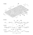
- FIG. 9 illustrates a corrugated sheet 120 included in a heat insulator 3
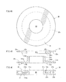
- FIG. 10 is a schematic front view of the cushioning device 10 in an attached state.
- FIG. 9( a ) is an isometric view of the corrugated sheet 120
- FIG. 9( b ) is a cross-sectional view of the corrugated sheet 120 taken along line I-I in FIG. 9( a )
- FIG. 9( c ) is a cross-sectional view of the corrugated sheet 120 taken along line II-II in FIG. 9( a )
- FIG. 9( d ) is a cross-sectional view of the corrugated sheet 120 taken along line III-III in FIG. 9( a ).
- the engine 2 of a vehicle of an automobile or the like is provided with an exhaust manifold 1 attached on a side surface thereof in order to discharge combustion exhaust gas (see FIG. 10 ).
- the exhaust manifold 1 is covered with the heat insulator 3 .
- the cushioning device 10 is of a floating mount structure for attaching the heat insulator 3 to the exhaust manifold 1 , and includes the multi-stage coiled and spiral spring 50 for cushioning the vibration, the grommet 20 and the collar member 30 .
- the collar member 30 has a cylindrical shape which is low as compared with the diameter thereof and is formed of an iron-based material such as SPCC or the like. As shown in FIG. 4( a ), the collar member 30 has a bolt hole 40 at a central position thereof as seen in a plan view for allowing an attaching bolt 42 to pass therethrough.
- the collar member 30 has a fitting recess 33 in a side surface thereof 20 , for allowing a collar member attaching portion 53 of the multi-stage coiled and spiral spring 50 described later to fit thereinto.
- the collar member 30 includes an upper collar 31 which is convexed downward and a lower collar 32 which is caulked with the upper collar 31 .
- the upper collar 31 includes a ring portion 31 a located in a diametrically outer part thereof, an annular thick portion 31 b located diametrically inner to the ring portion 31 a , and a fitting cylinder portion 31 c protruding upward from an inner circumferential edge of the thick portion 31 b .
- the ring portion 31 a , the thick portion 31 b and the fitting cylinder portion 31 c are integrated together.
- the thick portion 31 b has a bottom surface 31 ba.
- the lower collar 32 includes a ring portion 32 a located on the bottom side and in a diametrically outer part thereof so as to correspond to the ring portion 31 a , and an annular thick portion 32 b .
- a fitting opening 32 c is defined by an inner circumferential edge of the annular thick portion 32 b and allows the fitting cylinder portion 31 c to fit thereinto.
- the thick portion 32 b has a top surface 32 ba .
- the ring portions 31 a and 32 a are respectively thinner than the thick portions 31 b and 32 b by approximately a radius of a wiring member which forms the multi-stage coiled and spiral spring 50 described later and has a circular cross-section.
- the upper collar 31 and the lower collar 32 having such a structure are integrated together as follows.
- the bottom surface 31 ba of the thick portion 31 b of the upper collar 31 and the top surface 32 ba of the thick portion 32 b of the lower collar 32 are located to face each other, and the fitting cylinder portion 31 c inserted into the fitting opening 32 c is caulked in the diametrically outer direction.
- the ring portion 31 a of the upper collar 31 and the ring portion 32 a of the lower collar 32 form the fitting recess 33 which is annular as seen in a plan view and is concaved in the diametrically inner direction from the side surface of the cylindrical collar member 30 .
- the fitting recess 33 is formed by the ring portions 31 a and 32 a which face each other and are respectively thinner than the thick portions 31 b and 32 b by approximately the radius of the wiring member which forms the multi-stage coiled and spiral spring 50 . Therefore, the fitting recess 33 is a concaved portion which is annular as seen in a plan view and has a height slightly larger than a diameter of the wiring member which forms the multi-stage coiled and spiral spring 50 .
- the multi-stage coiled and spiral spring 50 is formed by winding the wiring member having a circular cross-section, and includes a diametrically outer spiral portion 51 and a diametrically inner multi-stage coiled portion 52 .
- the multi-stage coiled and spiral spring 50 includes the spiral portion 51 wound inner from the diametrically outer side while the position thereof in a height direction is gradually changed, and the multi-stage coiled portion 52 which is continued from a diametrically inner end of the spiral portion 51 and is wound in a cylindrical manner.
- the spiral portion 51 and the multi-stage coiled portion 52 although being formed of the same wiring member having a circular cross-section, have different pitches and thus have different spring constants. Namely, by changing the manner of winding from the spiral manner to the cylindrical manner, the multi-stage coiled and spiral spring 50 formed by winding one continuous wiring member having a circular cross-section has two different spring constants.
- the multi-stage coiled and spiral spring 50 includes the collar member attaching portion 53 formed at an end of the multi-stage coiled portion 52 and also a held portion 54 , which is held by a coupling portion 23 of the grommet 20 described later, on the diametrically outer side of the spiral portion 51 .
- the spiral portion 51 of the multi-stage coiled and spiral spring 50 will be described in more detail.
- the spiral portion 51 has the position thereof in the height direction (up-down direction in FIG. 5 ( b )) gradually changed along the spiral direction and has three spiral winds.
- the held portion 54 which is arcked is provided at the diametrically outer side of the spiral shape of the multi-stage coiled and spiral spring 50 , and the multi-stage coiled portion 52 is formed continuously from a center-side end of the spiral shape of the multi-stage coiled and spiral spring 50 .
- the multi-stage coiled portion 52 is continuous from the diametrically inner end of the spiral portion 51 , and is wound at a narrow pitch in the height direction and with an equal winding diameter.
- the collar member attaching portion 53 for attaching the multi-stage coiled and spiral spring 50 to the fitting recess 33 is provided.
- the collar member attaching portion 53 and the held portion 54 both have an arcked shape having a central angle of 270 degrees, which is 3 ⁇ 4 of a circle from an end thereof (see FIG. 5( a )).
- a circle defined by an inner circumference of the collar member attaching portion 53 has a diameter slightly larger, specifically by about 0.2 mm, than that of a circle 33 c defined by a circumferential surface of the fitting recess 33 of the collar member 30 . Accordingly, a gap S for improving the vibration-damping property is formed between the inner circumference of the collar member attaching portion 53 and the circle 33 c defined by the circumferential surface of the fitting recess 33 (see an enlarged view of “a” portion in FIG. 2( b ).
- the multi-stage coiled and spiral spring 50 is formed of a wiring member which is formed of a stainless steel such as SUS304 or the like.
- the multi-stage coiled and spiral spring 50 includes the spiral portion 51 and the multi-stage coiled portion 52 .
- the wiring member may have a cross-section of an elliptical shape, generally rectangular shape, or any other optional shape of a closed curved surface.
- the shape of the cross-section of the wiring member may be appropriately selectable as well as the diameter, the material or the number of winds of the wiring member.
- the grommet 20 includes a first holding portion 21 for holding the heat insulator 3 , a second holding portion 22 for holding the multi-stage coiled and spiral spring 50 , and the coupling portion 23 for coupling the first holding portion 21 and the second holding portion 22 to each other.
- the grommet 20 has an insertion hole 24 at a central position as seen in a plan view.
- the grommet 20 has an annular shape having an S-shaped cross-section.
- the first holding portion 21 for holding the heat insulator 3 on a diametrically outer side has an end having an inverted-J-shaped cross-section which is opened outward as follows. A portion of a prescribed length in a radial direction, which is extended internally from an outer circumferential edge of the annular metal plate, is extended downward in FIG. 7 and then is returned externally from the diametrically inner side.
- the first holding portion 21 is formed to have a thickness which is sufficient to hold the heat insulator 3 described later.
- the second holding portion 22 for holding the multi-stage coiled and spiral spring 50 on the diametrically inner side has an end having an inverted-J-shaped cross-section which is opened inward as follows. A portion of a prescribed length in the radial direction, which is extended externally from the diametrically inner side of the annular metal plate, is extended upward in FIG. 7 and then is returned internally from the diametrically outer side.
- the second holding portion 22 is formed to have a thickness which is sufficient to hold the multi-stage coiled and spiral spring 50 .
- the gap S is formed between the circle 33 c defined by the circumferential surface of the fitting recess 33 of the collar member 30 and the inner circumference of the collar member attaching portion 53 of the multi-stage coiled and spiral spring 50 , and the collar member attaching portion 53 can be wound along a range of 3 ⁇ 4 of the circle 33 c defined by the circumferential surface of the fitting recess 33 .
- the held portion 54 of the spiral portion 51 of the multi-stage coiled and spiral spring 50 is fitted into the second holding portion 22 of the grommet 20 , and thus the grommet 20 and the multi-stage coiled and spiral spring 50 are assembled together.
- the gap S is formed between the inner circumferential surface of the second holding portion 22 of the grommet 20 and the outer circumference of the held portion 54 of the multi-stage coiled and spiral spring 50 , and the held portion 54 is located along a range of 3 ⁇ 4 of the inner circumferential surface of the second holding portion 22 .
- the second holding portion 22 for holding the held portion 54 is located at a higher level than the collar member 30 engaged with the collar member attaching portion 53 at the fitting recess 33 .
- the cushioning device 10 having such a structure is attached to attaching holes 3 a of the heat insulator 3 and secured to the bolt boss 41 formed on the exhaust manifold 1 by the attaching bolt 42 screwed into the bolt boss 41 .
- the heat insulator 3 is formed so as to cover the exhaust manifold 1 attached to the side surface of the engine 2 , and is secured to a plurality of the bolt bosses 41 provided on the exhaust manifold 1 via the cushioning device 10 by the attaching bolts 42 .
- the heat insulator 3 having such a shape that covers the exhaust manifold 1 is conventionally formed of an aluminum-plated steel plate but is today formed of a corrugated sheet 120 put into a prescribed shape.
- the corrugated sheet 120 is formed of a light metal material, for example, aluminum and is corrugated in two directions perpendicular to each other (see FIG. 9 ).
- the corrugated sheet 120 is a corrugated aluminum plate. As shown in FIG. 9( b ) and FIG. 9( c ), the corrugated sheet 120 includes ridges 121 and troughs 122 alternately and continuously located in an X direction. As shown in FIG. 9 ( d ), in a Y direction, the ridges 121 and the troughs 122 each have apexes ( 121 a , 122 a ) and bottoms ( 121 b , 122 b ) located at a certain interval.
- the ridges 121 and the troughs 122 each have wider portions and narrow portions alternately located at a certain interval in the X direction to form a corrugated shape.
- the ridges 121 extending in the Y direction and the troughs 122 extending in the Y direction are alternately located in the X direction.
- the ridges 121 include the apexes 121 a and the bottoms 121 b , both rising from the troughs 122 , located alternately.
- the troughs 122 include flat portions 122 a as the apexes and concaved portions 122 b as the bottoms located alternately.
- the attaching holes 3 a are formed at positions corresponding to the bolt bosses 41 provided on the exhaust manifold 1 .
- the corrugated shape is squashed in the vicinity of the attaching holes 3 a to form generally flat squashed portions 3 b , and the squashed portions 3 b are held by the first holding portion 21 .
- the heat insulator 3 has a three-dimensional shape.
- One of the two directions perpendicular to each other of the corrugated shape is defined as a direction crossing a main ridgeline portion forming the three-dimensional shape.
- the heat insulator 3 is formed to have a three-dimensional shape along the three-dimensional external shape of the exhaust manifold 1 as described above. Therefore, the heat insulator 3 has one or a plurality of ridgeline portions, which are bending portions. In this example, the heat insulator 3 is pressed to have a shape such that a longitudinal direction of the corrugated shape crosses a main ridgeline portion among these plurality of ridgeline portions.
- the “main ridgeline portion” is a portion in which folding portions having a relatively large radius of curvature characterizing the overall shape of the heat insulator 3 are continuous. Namely, among various large and small folding portions of the heat insulator 3 , a folding portion which is relatively long and thus substantially determines the external shape of the heat insulator 3 is the “main ridgeline portion”.
- one direction of the corrugated shape of the heat insulator 3 is defined as a direction crossing the main ridgeline portion, preferably as a direction perpendicularly crossing the main ridgeline portion. Therefore, the corrugated shape acts as ribs against the vibration centered around the ridgeline portion. Thus, the heat insulator 3 can be suppressed from vibrating and thus prevented from cracking. As a result, the quality of the heat insulator 3 can be significantly improved.
- the spring constant confirmation test was performed for confirming the spring constant of the multi-stage coiled and spiral spring 50 attached to the cushioning device 10 .
- a tensile force in the height direction is caused to act on the multi-stage coiled and spiral spring 50 , and the spring constant at this point was calculated.
- FIG. 11 it was confirmed that a second spring constant range having a different spring constant from that of a first spring constant range appears after the displacement amount exceeds a prescribed value, namely, an apparent spring constant exists.
- the heat insulator 3 was secured to a vibration machine by use of the heat insulator 3 .
- the heat insulator 3 was secured to the vibration machine by use of a cushioning device including a spiral cushioning member.
- the solid line represents the result obtained with the cushioning device 10
- the dashed line represents the result of the comparative example.
- both the cushioning device 10 and the cushioning device in the comparative example both have a higher cushioning effect of absorbing vibration than that of a conventional cushioning device as shown in, for example, FIG. 15 , but that the resonance peak in the comparative example occurs in the engine normal range (see FIG. 12 ).
- the engine normal range is a frequency range of 30 to 230 Hz corresponding to the range from the idling rotation rate (850 rpm) to the full rotation rate (7000 rpm).
- the acceleration of the heat insulator 3 which was vibrating was measured in the case where the heat insulator 3 was mounted on a real vehicle by use of the cushioning device 10 and in the case where the heat insulator 3 was mounted on the real vehicle by use of the cushioning device in the comparative example, and the obtained accelerations was compared.
- the heat insulating 3 was mounted on an engine in a vehicle of 1300 cc by use of the cushioning device 10 and by the cushioning device in the comparative example, and the rotation rate of the engine was adjusted by an operation of the driver's foot on an accelerator pedal, and a tracking measurement of the heat insulator 3 was performed.
- the cushioning device 10 is a device to be located between the bolt boss 41 provided on the exhaust manifold 1 , which is a vibration source, and the heat insulator 3 , which is a connection target.
- the cushioning device 10 connects the bolt boss 41 provided on the exhaust manifold 1 and the heat insulator 3 to each other and cushions transmission of a vibration from the bolt boss 41 provided on the exhaust manifold 1 to the heat insulator 3 .
- the cushioning device 10 can provide a stable and superb vibration-damping property.
- the multi-stage coiled and spiral spring 50 is formed of a wiring member having a spiral shape as seen in a plan view.
- the collar member attaching portion 53 for allowing the collar member 30 to be attached thereto is provided at the diametrically central part of the spiral shape as seen in a plan view, and the fitting recess 33 for holding the collar member attaching portion 53 is provided on the diametrically outer side of the collar member 30 . Therefore, the vibration transmitted from the collar member 30 to the multi-stage coiled and spiral spring 50 causes the multi-stage coiled and spiral spring 50 itself formed of the wiring member having a spiral shape as seen in a plan view to make a flexural motion.
- the cushioning device 10 converts the vibration energy of the vibration transmitted from the collar member 30 into a kinetic energy of the flexure of the multi-stage coiled and spiral spring 50 , and thus can suppress the vibration from being transmitted to the heat insulator 3 .
- the function of the gap 17 of the conventional art which is actively formed in the axial direction and the radial direction (planar direction) between the collar member 10 and the cushioning member 8 of the cushioning device 5 such that the collar member 10 and the cushioning member 8 are loosely movable, is realized by a clearance between the winds of the wiring member of the spiral portion 51 of the multi-stage coiled and spiral spring 50 .
- the transmission of the input vibration is suppressed; namely, a superb vibration-damping property is realized.
- the collar member attaching portion 53 for allowing the collar member 30 to be attached thereto is provided at the diametrically central part of the spiral shape as seen in a plan view, and the fitting recess 33 for holding the collar member attaching portion 53 is provided on the diametrically outer side of the collar member 30 . Therefore, the vibration can be suppressed from being transmitted without any collision of the multi-stage coiled and spiral spring 50 against the collar member 30 . Accordingly, the vibration is suppressed from being transmitted from the collar member 30 to the multi-stage coiled and spiral spring 50 with no rattling noise caused by the collision of the multi-stage coiled and spiral spring 50 against the collar member 30 . Namely, a superb vibration-damping property can be provided.
- the multi-stage coiled and spiral spring 50 is formed of a wiring member formed by molding to have a spiral shape as seen in a plan view. Therefore, it is not necessary to handle minute inorganic fibers, which solves the difficulty in managing the fiber length in a step of cutting the inorganic fibers to a prescribed length or the difficulty in managing the size precision so that the size precision is kept high in a step of processing the fibers into final products. Owing to this, the size precision can be improved, and the precision and the stability of the vibration-damping property of the cushioning device 10 can be improved.
- the exhaust manifold 1 which is a vibration source
- the heat insulator 3 can be connected to each other with no vibration being transmitted.
- the multi-stage coiled portion 52 having a spring constant higher than that of the spiral portion 51 is provided on the diametrically inner side of the spiral shape as seen in a plan view of the multi-stage coiled and spiral spring 50 .
- the cushioning device 10 can have desired cushioning characteristics. This will be described in more detail.
- One multi-stage coiled and spiral spring 50 having a spiral shape as seen in a plan view includes the multi-stage coiled portion 52 having a high apparent spring constant and the spiral portion 51 having a spring constant lower than that of the multi-stage coiled portion 52 .
- the cushioning member and the cushioning device can have desired cushioning characteristics.
- the multi-stage coiled portion 52 having a high apparent spring constant is wound in a generally cylindrical shape extending in a height direction; and the spiral portion 51 having a spring constant lower than that of the multi-stage coiled portion 52 is formed to have a spiral shape having a level in the height direction gradually changed along a spiral direction. Owing to this, the cushioning device 10 can have desired cushioning characteristics easily.
- the multi-stage coiled portion 52 and in the spiral portion 51 the winding pitch of the wiring member is different. Therefore, the multi-stage coiled portion 52 having a high apparent spring constant and the spiral portion 51 having a spring constant lower than that of the multi-stage coiled portion 52 can be provided easily by use of the wiring member having the same spring constant and the same cross-sectional diameter. Namely, as described above, the spring constant of the multi-stage coiled and spiral spring 50 can be appropriately set easily in accordance with the vibration behavior such that the multi-stage coiled and spiral spring 50 has both of the multi-stage coiled portion 52 having a high apparent spring constant and the portion having a spring constant lower than that of the multi-stage coiled portion 52 . Accordingly, the multi-stage coiled and spiral spring 50 and the cushioning device 10 can have desired cushioning characteristics.
- the multi-stage coiled and spiral spring 50 includes the cylindrical multi-stage coiled portion 52 and the spiral portion 51 . Owing to this, the multi-stage coiled and spiral spring 50 can have a more desirable spring constant as compared with a multi-stage coiled and spiral spring formed merely of the spiral portion 51 or merely of the multi-stage coiled portion 52 so as to have a desired height.
- the wiring member of the multi-stage coiled and spiral spring 50 needs to be long.
- the multi-stage coiled portion 52 is formed of a wiring member having a length appropriate for guaranteeing the desired vibration-damping property in the state where the outer diameter of the wiring member is restricted by the second holding portion 22 of the grommet 20 .
- the number of winds of the wiring member used to form the spiral shape is increased, and thus the winding pitch of the wiring member in the planar direction is decreased.
- the vibration absorption performance in the planar direction is lowered, which inhibits the improvement of the vibration-damping property.
- the multi-stage coiled and spiral spring 50 includes the cylindrical multi-stage coiled portion 52 and the spiral portion 51 , the elasticity in the diametric direction and the height direction is guaranteed by the spiral portion 51 , and a desired height is realized by the multi-stage coiled portion 52 having a high spring constant.
- the multi-stage coiled and spiral spring 50 can have a desired spring constant.
- the multi-stage coiled and spiral spring 50 is located in such a direction that the held portion 54 is farther from the exhaust manifold 1 than the collar member attaching portion 53 is. Owing to this, the vibration-damping property of the cushioning device 10 can be improved.
- the multi-stage coiled and spiral spring 50 includes the multi-stage coiled portion 52 and the spiral portion 51 . Owing to this, the elasticity of the multi-stage coiled and spiral spring 50 can be adjusted in the height direction in addition to the planar direction by use of two spring constants. Namely, the elasticity of the multi-stage coiled and spiral spring 50 , which significantly influences the vibration-damping property of the multi-stage coiled and spiral spring 50 , can be adjusted three-dimensionally based on the two spring constants.
- the multi-stage coiled portion 52 is wound at a narrow pitch in the height direction and with an equal winding diameter. Therefore, it is considered that the friction between the winds of the wound wiring member used to form the multi-stage coiled portion 52 also contributes to the vibration absorption effect.
- the multi-stage coiled portion 52 is wound at a narrow pitch in the height direction and with an equal winding diameter. Therefore, a part of the wound winding member enters inside another part of the wound winding member which is adjacent to the part in the height direction and expands the another part in the diametrically outer direction against the elastic force. As a result, among vibrations input to the multi-stage coiled and spiral spring 50 , a vibration in the direction in which the held portion 54 and the collar member attaching portion 53 approach to each other can be absorbed.
- the multi-stage coiled and spiral spring 50 is located in such a direction that the held portion 54 is farther from the exhaust manifold 1 than the collar member attaching portion 53 is. Owing to this, the held portion 54 on the diametrically outer side of the multi-stage coiled and spiral spring 50 is farther from the exhaust manifold 1 than the collar member attaching portion 53 on the diametrically inner side is. Namely, the heat insulator 3 held by the first holding portion 21 of the coupling portion 23 , which holds the held portion 54 by the second holding portion 22 , is located farther from the exhaust manifold 1 than the collar member 30 wound around the collar member attaching portion 53 is.
- the cushioning device 10 by adopting the above-described structure, provides a still improved vibration-damping property.
- the collar member attaching portion 53 is included in the multi-stage coiled portion 52
- the held portion 54 is included in a diametrically outer part of the spiral portion 51 .
- the multi-stage coiled portion 52 is located on the diametrically inner side of the multi-stage coiled and spiral spring 50 on which the collar member attaching portion 53 is provided
- the spiral portion 51 is located on the diametrically outer side of the multi-stage coiled and spiral spring 50 on which the held portion 54 is provided.
- the vibration which is input via the collar member 30 is first input to the spiral portion 51 on the diametrically outer side and is cushioned by the elasticity in the planar direction and the height direction.
- the vibration which is cushioned by the spiral portion 51 is further cushioned by the multi-stage coiled portion having a high apparent spring constant. Therefore, the undesirable possibility that the heat insulator 3 itself collides against the exhaust manifold 1 can be further reduced. As a result, generation of noise caused by the collision of the heat insulator 3 itself against the exhaust manifold 1 can be suppressed.
- the collar member attaching portion 53 and the held portion 54 have an arcked shape; the second holding portion 22 has an annular shape as seen in a plan view; and the collar member 30 has a cylindrical shape, and the fitting recess 33 for allowing the collar member attaching portion 53 to fit thereinto is formed in a side surface of the cylindrical collar member 30 . Owing to this, the multi-stage coiled and spiral spring 50 and the collar member 30 can be fitted together easily, and the held portion 54 can be held by the second holding portion 22 .
- the collar member attaching portion 53 and the held portion 54 are formed to be arcked.
- the fitting recess 33 for allowing the collar member attaching portion 53 to fit thereinto is formed in the side surface of the cylindrical collar member 30 . Therefore, the collar member attaching portion 53 formed to be arcked is fitted into the fitting recess 33 formed in the side surface of the cylindrical collar member 30 .
- the multi-stage coiled and spiral spring 50 and the collar member 30 can be fitted into each other easily.
- the multi-stage coiled and spiral spring 50 and the collar member 30 can be fitted into each other easily regardless of the position of the multi-stage coiled and spiral spring 50 in the circumferential direction with respect to the collar member 30 .
- the multi-stage coiled and spiral spring 50 and the collar member 30 can be fitted into each other easily, and also the held portion 54 can be held by the second holding portion 22 . Therefore, the ease of assembly of the cushioning device 10 can be improved.
- the number of components can be reduced as compared with the case where, for example, the collar member attaching portion 53 of the multi-stage coiled and spiral spring 50 is fitted into the fitting recess 33 of the collar member 30 by use of a separate member. Accordingly, the cushioning device 10 can be reduced in weight and can be produced at lower cost.
- the gap S for improving the vibration-damping property is provided between the fitting recess 33 and the collar member attaching portion 53 . Therefore, the vibration-damping property of the cushioning device 10 can be further improved. This will be described in more detail.
- the gap S for improving the vibration-damping property is provided in the state where the collar member attaching portion 53 formed to be arcked is held by the fitting recess 33 ; namely, the gap S of only about 0.2 mm is provided for improving the vibration-damping property. Therefore, unlike in the cushioning device 5 of the conventional art, in which the gap 17 (see FIG.
- the vibration input via the collar member 30 can be absorbed by the gap S.
- the gap S can also block the heat transmission.
- the collar member 30 includes the upper collar 31 and the lower collar 32 assembled together.
- the upper collar 31 and the lower collar 32 each have a generally L-shaped cross-section.
- the upper collar 31 and the lower collar 32 respectively include thick portions 31 b and 32 b which have an appropriate thickness in a diametric direction of the collar member and also include disc-shaped ring portions 31 a and 32 a protruding in the diametrically outer direction from one of a top end and a bottom end of the respective thick portions.
- the upper collar 31 and the lower collar 32 are assembled such that the ring portions 31 a and 32 a are located on the outer side and such that the bottom surface 31 ba of the thick portion 31 b and the top surface 32 ba of the thick portion 32 b face each other. Owing to this, the product reliability of the cushioning device 10 having a high vibration-damping property can be improved.
- the collar member 30 includes the upper collar 31 and the lower collar 32 assembled together.
- the upper collar 31 and the lower collar 32 each have a generally L-shaped cross-section.
- the upper collar 31 and the lower collar 32 respectively include thick portions 31 b and 32 b having an appropriate thickness in the diametric direction of the collar member and also include disc-shaped ring portions 31 a and 32 a protruding in the diametrically outer direction from one of the top end and the bottom end of the respective thick portions.
- the upper collar 31 and the lower collar 32 are assembled such that the ring portions 31 a and 32 a are located on the outer side and such that the bottom surface 31 ba of the thick portion 31 b and the top surface 32 ba of the thick portion 32 b face each other. Owing to this, a space enclosed by the thick portions 31 b and 32 b facing each other and the ring portions 31 a and 32 a can form the fitting recess 33 .
- the bottom surface 31 ba of the thick portion 31 b and the top surface 32 ba of the thick portion 32 b face each other in the state where the upper collar 31 and the lower collar 32 are assembled. Therefore, during a step of inserting the attaching bolt 42 into the bolt hole 40 of the assembled collar member 30 and thus securing the attaching bolt 42 to the exhaust manifold 1 , the fitting recess 33 defined by the ring portions 31 a and 32 a can be prevented from being deformed due to the tightening pressure of the attaching bolt 42 . Accordingly, the gap S for improving the vibration-damping property can be formed without fail between the collar member attaching portion 53 and the fitting recess 33 . The vibration input via the collar member 30 can be absorbed by the gap S without causing a colliding noise at the collar member attaching portion 53 or the fitting recess 33 . In addition, transmission of heat can be blocked by the gap S.
- the heat insulator 3 is formed of one or a plurality of aluminum alloy plates of a three-dimensional shape having a corrugated shape extending in directions crossing each other.
- the corrugated shape of the heat insulator 3 is squashed to form generally flat squashed portions 3 b .
- One of two directions crossing each other of the heat insulator 3 is defined as a direction crossing the main ridgeline portion for forming the three-dimensional shape.
- the squashed portions 3 b of the multi-stage coiled and spiral spring 50 are held by the first holding portion 21 .
- the heat insulator 3 can, for example, suppress the heat radiation and the vibration transmission from the engine 2 of an automobile or the like and/or the exhaust manifold 1 thereof.
- the heat insulator 3 formed of a material having an appropriate heat-resistant performance is attached by use of the above-described cushioning device having a high vibration-damping property. Therefore, the heat radiation from the engine 2 and/or the exhaust manifold 1 thereof, which are heat sources, can be prevented. In addition, the vibration transmission from the engine 2 and/or the exhaust manifold 1 thereof, which are also vibration sources, to the heat insulator 3 can be prevented.
- the heat insulator 3 can be attached in a high vibration-damping state as compared with the case where, for example, the heat insulator 3 itself resonates with the vibration input from the vibration source.
- the heat insulator 3 is formed of one or a plurality of aluminum alloy plates having a corrugated shape extending in directions crossing each other. Therefore, the heat insulator 3 is highly deformable. Thus, even in the case where, for example, the engine 2 and/or the exhaust manifold 1 thereof has a complicated shape, the heat insulator 3 can be shaped in accordance therewith. Since the heat insulator 3 shaped in accordance with the shapes of the engine 2 and/or the exhaust manifold 1 thereof can be attached, the heat radiation from the engine 2 and/or the exhaust manifold 1 thereof can be prevented with more certainty.
- the directions crossing each other may be the X direction and the Y direction, which cross each other perpendicularly.
- the corrugated shape is as follows.
- the ridges extending in the Y direction and the troughs extending in the Y direction are alternately located in the X direction.
- the ridges include the apexes 121 a and the bottoms 121 b , rising from the troughs, alternately located in the Y direction.
- the troughs include the flat portions and the concaved portions alternately located in the Y direction.
- Each apex 121 a includes a pair of side walls rising from the troughs in an inverted trapezoidal shape and a relatively flat apex portion connecting tips of the side walls to each other.
- the apex 121 a is curved inward so that a top portion of the apex 121 a is wider than a base portion thereof.
- Each concaved portion includes a pair of side walls falling from the bottoms 121 b and a recessed portion connecting tips of the side walls to each other.
- the apexes 121 a and the flat portions are intermittently continuous in the X direction, and the bottoms 121 b and the concaved portions are intermittently continuous in the X direction. Therefore, the shape processability of the heat insulator 3 can be further improved.
- the heat insulator 3 can be formed into a shape more matching the shapes of the engine 2 and/or the exhaust manifold 1 thereof, to which the heat insulator 3 is to be attached. As a result, the heat radiation from the engine 2 and/or the exhaust manifold 1 thereof can be prevented with more certainty.
- the ring portion 32 a of the lower collar 32 may have a large-diameter flange portion 35 which has a large diameter and is contactable with the second holding portion 22 as shown in FIG. 14 .
- a cushioning device 10 having a higher vibration-damping property can be provided.
- the ring portion 32 a of the lower collar 32 among the upper collar 31 and the lower collar 32 included in the collar ember 30 , has a large-diameter flange portion 35 which has a large diameter and is contactable with the second holding portion 22 . Owing to this, even when the grommet 20 to be joined to the heat insulator 3 is displaced toward the exhaust manifold 1 due to a large amplitude, the large-diameter flange portion 35 included in the ring portion 32 a of the lower collar 32 contacts the second holding portion 22 and thus can prevent the second holding portion 22 from directly contacting the exhaust manifold 1 . Accordingly, the vibration-damping property can be provided without fail even against a large vibration caused by, for example, resonance or the like.
- the ring portion 32 a of the lower collar 32 is formed to have a large diameter to form the large-diameter flange portion 35 .
- the large-diameter flange portion 35 as a separate member may be secured to the ring portion 32 a of the lower collar 32 .
- the cushioning device 10 in this example has been described as being used for attaching the heat insulator 3 to the exhaust manifold 1 which is to be mounted on the engine 2 of an automobile, but the present invention is not limited to such an example.
- the cushioning device according to the present invention may be used to attach any of covers for various uses, which are to be attached to any other part of the automobile, for example, an undercover for covering the bottom of the vehicle body.
- the cushioning device according to the present invention may also be used to attach any of covers for various uses to an object other than an automobile.
- the vibration target member according to the present invention corresponds to the exhaust manifold 1 in the above embodiment; and similarly,
- connection target member corresponds to the heat insulator 3 ;
- the cushioning member corresponds to the multi-stage coiled and spiral spring 50 ;
- the coupling member corresponds to the grommet 20 ;
- the tightening member corresponds to the attaching bolt 42 ;
- the tightening member insertion portion corresponds to the bolt hole 40 ;
- the cushioning member holding portion and the fitting recess correspond to the fitting recess 33 ;
- the another portion and the spiral portion correspond to the spiral portion 51 ;
- the high spring portion and the coiled portion correspond to the multi-stage coiled portion 52 ;
- the thick ring portions correspond to the thick portions 31 b and 32 b;
- the end portions of the thick ring portions correspond to the bottom surface 31 ba of the thick portion 31 b and the top surface 32 ba of the thick portion 32 b;
- the flange portions correspond to the ring portions 31 a and 32 a;
- the collar member components correspond to the upper collar 31 and the lower collar 32 ;
- connection target member-side component corresponds to the upper collar 31 ;
- the internal combustion engine corresponds to the engine 2 ;
- the exhaust path corresponds to the exhaust manifold 1 ;
- the squashing target portion corresponds to the squashed portion 3 b;
- the first direction corresponds to the Y direction
- the second direction corresponds to the X direction
- the first rising portion corresponds to the apex 121 a ;
- the second holding portion 22 , the coupling portion 23 and the first holding portion 21 of the collar member 30 are located in this order from the side of the bolt boss 41 provided on the exhaust manifold 1 .
- these elements may be located in the order of the first holding portion 21 , the coupling portion 23 and the second holding portion 22 from the side of the bolt boss 41 provided on the exhaust manifold 1 .
- the multi-stage coiled portion 52 having an apparent spring constant higher than that of the spiral portion 51 is formed of a wiring member wound in a cylindrical shape at a narrow pitch.
- the multi-stage coiled portion 52 may be formed of a winding member having a higher spring constant or a winding member having the same spring constant but having a larger diameter.
- the spiral portion 51 is provided on the diametrically outer side of the multi-stage coiled and spiral spring 50 , and the multi-stage coiled portion 52 is provided on the diametrically inner side.
- the spiral portion 51 may be provided on the diametrically inner side of the multi-stage coiled and spiral spring 50
- the multi-stage coiled portion 52 may be provided on the diametrically outer side.
- the grommet 20 includes the first holding portion 21 for holding the heat insulator 3 on the diametrically outer side, the second holding portion 22 for holding the multi-stage coiled and spiral spring 50 on the diametrically inner side, and the coupling portion 23 for coupling the first holding portion 21 and the second holding portion 22 to each other.
- the grommet 20 has an annular shape having an S-shaped cross-section. It is sufficient that the grommet 20 holds the heat insulator 3 on the diametrically outer side and holds the multi-stage coiled and spiral spring 50 on the diametrically inner side.
- the grommet 20 may have inverted U-shaped or V-shaped holding portions in an outer direction for holding the heat insulator 3 and the multi-stage coiled and spiral spring 50 and also an annular member for coupling the holding portions to each other.
Landscapes
- Engineering & Computer Science (AREA)
- General Engineering & Computer Science (AREA)
- Mechanical Engineering (AREA)
- Chemical & Material Sciences (AREA)
- Combustion & Propulsion (AREA)
- Physics & Mathematics (AREA)
- Acoustics & Sound (AREA)
- Aviation & Aerospace Engineering (AREA)
- Vibration Prevention Devices (AREA)
- Exhaust Silencers (AREA)
- Springs (AREA)
Applications Claiming Priority (3)
| Application Number | Priority Date | Filing Date | Title |
|---|---|---|---|
| JP2010-286348 | 2010-12-22 | ||
| JP2010286348A JP4901992B1 (ja) | 2010-12-22 | 2010-12-22 | 緩衝装置及び金属製カバー |
| PCT/JP2011/057992 WO2012086224A1 (ja) | 2010-12-22 | 2011-03-30 | 緩衝装置及び金属製カバー |
Related Parent Applications (1)
| Application Number | Title | Priority Date | Filing Date |
|---|---|---|---|
| PCT/JP2011/057992 Continuation WO2012086224A1 (ja) | 2010-12-22 | 2011-03-30 | 緩衝装置及び金属製カバー |
Publications (2)
| Publication Number | Publication Date |
|---|---|
| US20130241122A1 US20130241122A1 (en) | 2013-09-19 |
| US8899376B2 true US8899376B2 (en) | 2014-12-02 |
Family
ID=46060701
Family Applications (1)
| Application Number | Title | Priority Date | Filing Date |
|---|---|---|---|
| US13/724,998 Active 2031-10-03 US8899376B2 (en) | 2010-12-22 | 2012-12-21 | Cushioning device and metal cover |
Country Status (6)
| Country | Link |
|---|---|
| US (1) | US8899376B2 (ko) |
| EP (1) | EP2565488B1 (ko) |
| JP (1) | JP4901992B1 (ko) |
| KR (1) | KR101404684B1 (ko) |
| CN (1) | CN102985719B (ko) |
| WO (1) | WO2012086224A1 (ko) |
Cited By (9)
| Publication number | Priority date | Publication date | Assignee | Title |
|---|---|---|---|---|
| US20180023657A1 (en) * | 2015-01-30 | 2018-01-25 | Nichias Corporation | Connector and shielding body |
| US9964175B2 (en) | 2015-04-24 | 2018-05-08 | Federal-Mogul Llc | Heat and vibration mounting isolator for a heat shield, heat shield assembly and method of construction thereof |
| US20180215329A1 (en) * | 2015-07-24 | 2018-08-02 | Dana Automotive Systems Group, Llc | Insulating isolator assembly |
| US20180245614A1 (en) * | 2015-10-09 | 2018-08-30 | Nichias Corporation | Connector |
| US20190172441A1 (en) * | 2017-12-05 | 2019-06-06 | GM Global Technology Operations LLC | Passive sound enhancement system for a vehicle |
| US10854184B2 (en) | 2018-12-04 | 2020-12-01 | Ford Global Technologies, Llc | Friction damped insert for highly stressed engineering components |
| US10971126B1 (en) * | 2020-01-08 | 2021-04-06 | Wilson Audio Specialties, Inc. | Vibration damper |
| US20210268410A1 (en) * | 2020-02-28 | 2021-09-02 | Andritz Inc. | Rotary drum filter deck assembly comprising a clip |
| US11408323B2 (en) * | 2020-02-06 | 2022-08-09 | Hyundai Motor Company | Exhaust manifold heat dissipation cover coupling device for thermal stress and vibration deflection |
Families Citing this family (9)
| Publication number | Priority date | Publication date | Assignee | Title |
|---|---|---|---|---|
| JP5885258B2 (ja) * | 2013-05-21 | 2016-03-15 | トヨタ自動車株式会社 | ヒートインシュレータの締結構造 |
| CN105065523B (zh) * | 2015-07-20 | 2017-07-18 | 安徽舒城华云弹簧制造有限公司 | 弹簧及其固定装置 |
| DE102016106150A1 (de) * | 2016-04-05 | 2017-10-05 | Elringklinger Ag | Befestigungsvorrichtung für ein Abschirmteil, insbesondere für ein Hitzeschild sowie Abschirmteil aufweisend zumindest eine Befestigungsvorrichtung |
| DE102016106152A1 (de) * | 2016-04-05 | 2017-10-05 | Elringklinger Ag | Befestigungsvorrichtung für eine Entkopplungsvorrichtung an einem Abschirmteil, Entkopplungsvorrichtung aufweisend die Befestigungsvorrichtung sowie Abschirmteil aufweisend die Entkopplungsvorrichtung |
| JP6177985B1 (ja) * | 2016-11-24 | 2017-08-09 | 三和パッキング工業株式会社 | 緩衝装置および金属カバー |
| JP6434069B2 (ja) | 2017-02-01 | 2018-12-05 | ニチアス株式会社 | 連結具 |
| US20210239028A1 (en) * | 2019-01-28 | 2021-08-05 | Sanwa Packing Industry Co., Ltd. | Shock absorber and metal cover |
| CN112742328B (zh) * | 2021-01-05 | 2022-05-24 | 湖北山特莱新材料有限公司 | 一种水溶性聚酯浆料酯化反应系统中的反应釜组件 |
| US20230125356A1 (en) * | 2021-10-25 | 2023-04-27 | Ophir Optronics Solutions Ltd. | Zoom Lens Assembly with Flat Coil Extension Spring Termination |
Citations (14)
| Publication number | Priority date | Publication date | Assignee | Title |
|---|---|---|---|---|
| US3028138A (en) * | 1958-08-06 | 1962-04-03 | Wells & Company Ltd A | Anti-vibration mountings |
| US3107905A (en) * | 1960-10-19 | 1963-10-22 | Charles D Lucas | Belleville spring elastic suspension |
| US4498433A (en) * | 1979-05-18 | 1985-02-12 | Nissan Motor Company, Limited | Member such as an engine cover adjacent to an automotive engine |
| JPS6246294B2 (ko) | 1983-09-08 | 1987-10-01 | Tokyo Shibaura Electric Co | |
| US6318734B1 (en) * | 1999-12-21 | 2001-11-20 | Dana Corporation | Gasket with integral support |
| US6561312B2 (en) * | 2000-05-03 | 2003-05-13 | Elring Klinger Ag | Device for in particular acoustically uncoupled mounting |
| US6565158B2 (en) * | 2000-12-11 | 2003-05-20 | The Yokohama Rubber Co., Ltd. | Automotive road wheel and attaching structure of the same |
| JP2004360496A (ja) | 2003-06-02 | 2004-12-24 | Sanwa Packing Kogyo Co Ltd | 緩衝装置及び金属製カバー |
| US20050028519A1 (en) * | 2003-07-11 | 2005-02-10 | Nichias Corporation | Buffer washer member and vibration and heat insulating board having the same |
| JP2005133594A (ja) | 2003-10-29 | 2005-05-26 | Nichias Corp | 防振遮熱板 |
| US20050140075A1 (en) * | 2003-12-25 | 2005-06-30 | Sanwa Packing Industry Co., Ltd. | Vibration damping mount and metal heat shield |
| US7065963B2 (en) * | 2003-07-11 | 2006-06-27 | Nichias Corporation | Vibration and heat insulating board |
| US20100101528A1 (en) * | 2008-10-29 | 2010-04-29 | Gm Global Technology Operations, Inc. | Acoustic bumpers with engine front cover hidden mounting |
| JP2010156372A (ja) * | 2008-12-26 | 2010-07-15 | Sanwa Packing Kogyo Co Ltd | マウント部材 |
Family Cites Families (2)
| Publication number | Priority date | Publication date | Assignee | Title |
|---|---|---|---|---|
| JPS6056836U (ja) * | 1983-09-28 | 1985-04-20 | 三菱自動車工業株式会社 | 変形円錐コイルスプリング |
| JP3944174B2 (ja) * | 2004-02-18 | 2007-07-11 | 富士重工業株式会社 | 内燃機関接続パイプ用カバー |
-
2010
- 2010-12-22 JP JP2010286348A patent/JP4901992B1/ja active Active
-
2011
- 2011-03-30 WO PCT/JP2011/057992 patent/WO2012086224A1/ja active Application Filing
- 2011-03-30 CN CN201180030968.3A patent/CN102985719B/zh active Active
- 2011-03-30 KR KR1020127032417A patent/KR101404684B1/ko active IP Right Grant
- 2011-03-30 EP EP20110850948 patent/EP2565488B1/en active Active
-
2012
- 2012-12-21 US US13/724,998 patent/US8899376B2/en active Active
Patent Citations (15)
| Publication number | Priority date | Publication date | Assignee | Title |
|---|---|---|---|---|
| US3028138A (en) * | 1958-08-06 | 1962-04-03 | Wells & Company Ltd A | Anti-vibration mountings |
| US3107905A (en) * | 1960-10-19 | 1963-10-22 | Charles D Lucas | Belleville spring elastic suspension |
| US4498433A (en) * | 1979-05-18 | 1985-02-12 | Nissan Motor Company, Limited | Member such as an engine cover adjacent to an automotive engine |
| JPS6246294B2 (ko) | 1983-09-08 | 1987-10-01 | Tokyo Shibaura Electric Co | |
| US6318734B1 (en) * | 1999-12-21 | 2001-11-20 | Dana Corporation | Gasket with integral support |
| US6561312B2 (en) * | 2000-05-03 | 2003-05-13 | Elring Klinger Ag | Device for in particular acoustically uncoupled mounting |
| US6565158B2 (en) * | 2000-12-11 | 2003-05-20 | The Yokohama Rubber Co., Ltd. | Automotive road wheel and attaching structure of the same |
| JP2004360496A (ja) | 2003-06-02 | 2004-12-24 | Sanwa Packing Kogyo Co Ltd | 緩衝装置及び金属製カバー |
| US20050028519A1 (en) * | 2003-07-11 | 2005-02-10 | Nichias Corporation | Buffer washer member and vibration and heat insulating board having the same |
| US7065963B2 (en) * | 2003-07-11 | 2006-06-27 | Nichias Corporation | Vibration and heat insulating board |
| JP2005133594A (ja) | 2003-10-29 | 2005-05-26 | Nichias Corp | 防振遮熱板 |
| US7273128B2 (en) * | 2003-10-29 | 2007-09-25 | Nichias Corporation | Vibration proofing heat shield plate |
| US20050140075A1 (en) * | 2003-12-25 | 2005-06-30 | Sanwa Packing Industry Co., Ltd. | Vibration damping mount and metal heat shield |
| US20100101528A1 (en) * | 2008-10-29 | 2010-04-29 | Gm Global Technology Operations, Inc. | Acoustic bumpers with engine front cover hidden mounting |
| JP2010156372A (ja) * | 2008-12-26 | 2010-07-15 | Sanwa Packing Kogyo Co Ltd | マウント部材 |
Non-Patent Citations (1)
| Title |
|---|
| International Search Report issued in PCT/JP2011/057992, mailed Jul. 5, 2011, 2 pages. |
Cited By (12)
| Publication number | Priority date | Publication date | Assignee | Title |
|---|---|---|---|---|
| US20180023657A1 (en) * | 2015-01-30 | 2018-01-25 | Nichias Corporation | Connector and shielding body |
| US10753423B2 (en) * | 2015-01-30 | 2020-08-25 | Nichias Corporation | Connector and shielding body |
| US9964175B2 (en) | 2015-04-24 | 2018-05-08 | Federal-Mogul Llc | Heat and vibration mounting isolator for a heat shield, heat shield assembly and method of construction thereof |
| US20180215329A1 (en) * | 2015-07-24 | 2018-08-02 | Dana Automotive Systems Group, Llc | Insulating isolator assembly |
| US20180245614A1 (en) * | 2015-10-09 | 2018-08-30 | Nichias Corporation | Connector |
| US10920850B2 (en) * | 2015-10-09 | 2021-02-16 | Nichias Corporation | Connector |
| US11333216B2 (en) * | 2015-10-09 | 2022-05-17 | Nichias Corporation | Connector |
| US20190172441A1 (en) * | 2017-12-05 | 2019-06-06 | GM Global Technology Operations LLC | Passive sound enhancement system for a vehicle |
| US10854184B2 (en) | 2018-12-04 | 2020-12-01 | Ford Global Technologies, Llc | Friction damped insert for highly stressed engineering components |
| US10971126B1 (en) * | 2020-01-08 | 2021-04-06 | Wilson Audio Specialties, Inc. | Vibration damper |
| US11408323B2 (en) * | 2020-02-06 | 2022-08-09 | Hyundai Motor Company | Exhaust manifold heat dissipation cover coupling device for thermal stress and vibration deflection |
| US20210268410A1 (en) * | 2020-02-28 | 2021-09-02 | Andritz Inc. | Rotary drum filter deck assembly comprising a clip |
Also Published As
| Publication number | Publication date |
|---|---|
| EP2565488A1 (en) | 2013-03-06 |
| CN102985719B (zh) | 2015-06-17 |
| KR20130006710A (ko) | 2013-01-17 |
| KR101404684B1 (ko) | 2014-06-10 |
| WO2012086224A1 (ja) | 2012-06-28 |
| US20130241122A1 (en) | 2013-09-19 |
| JP2012132389A (ja) | 2012-07-12 |
| EP2565488A4 (en) | 2013-12-04 |
| JP4901992B1 (ja) | 2012-03-21 |
| CN102985719A (zh) | 2013-03-20 |
| EP2565488B1 (en) | 2015-05-13 |
Similar Documents
| Publication | Publication Date | Title |
|---|---|---|
| US8899376B2 (en) | Cushioning device and metal cover | |
| KR101356007B1 (ko) | 완충장치 및 금속제 커버 | |
| KR100955757B1 (ko) | 완충장치와 금속제 커버 | |
| US10151345B2 (en) | Center bearing bush unit for propeller shaft | |
| JP6585178B2 (ja) | 連結具 | |
| US9835219B2 (en) | Vibration damper for shielding plate | |
| US20210239028A1 (en) | Shock absorber and metal cover | |
| JP2018516332A (ja) | 熱シールドのための熱および振動取付アイソレータ、熱シールドアセンブリ、およびその構成方法 | |
| JP2007297980A (ja) | 金属製積層型カバー | |
| CN107208733B (zh) | 连结件和屏蔽体 | |
| KR20110100163A (ko) | 차음 구조 및 차음 커버 | |
| JP2016121639A (ja) | カバー部材 | |
| CN110234903B (zh) | 连结件 | |
| JP6126202B2 (ja) | エンジンコンパートメント部品のためのブラケット組立体 | |
| JP2006283951A (ja) | ダイナミックダンパ | |
| JP5141261B2 (ja) | 振動騒音低減構造 | |
| JP2023104422A (ja) | 内燃機関の排気系装置 | |
| JP2008275056A (ja) | ダイナミックダンパ |
Legal Events
| Date | Code | Title | Description |
|---|---|---|---|
| AS | Assignment |
Owner name: SANWA PACKING INDUSTRY CO., LTD., JAPAN Free format text: ASSIGNMENT OF ASSIGNORS INTEREST;ASSIGNOR:AKIMOTO, KAZUYO;REEL/FRAME:030108/0618 Effective date: 20121116 |
|
| STCF | Information on status: patent grant |
Free format text: PATENTED CASE |
|
| MAFP | Maintenance fee payment |
Free format text: PAYMENT OF MAINTENANCE FEE, 4TH YEAR, LARGE ENTITY (ORIGINAL EVENT CODE: M1551) Year of fee payment: 4 |
|
| MAFP | Maintenance fee payment |
Free format text: PAYMENT OF MAINTENANCE FEE, 8TH YEAR, LARGE ENTITY (ORIGINAL EVENT CODE: M1552); ENTITY STATUS OF PATENT OWNER: LARGE ENTITY Year of fee payment: 8 |