US8899370B1 - Casing for housing occupant protection device control unit - Google Patents
Casing for housing occupant protection device control unit Download PDFInfo
- Publication number
- US8899370B1 US8899370B1 US14/291,071 US201414291071A US8899370B1 US 8899370 B1 US8899370 B1 US 8899370B1 US 201414291071 A US201414291071 A US 201414291071A US 8899370 B1 US8899370 B1 US 8899370B1
- Authority
- US
- United States
- Prior art keywords
- base
- casing
- main body
- extension portion
- occupant protection
- Prior art date
- Legal status (The legal status is an assumption and is not a legal conclusion. Google has not performed a legal analysis and makes no representation as to the accuracy of the status listed.)
- Active
Links
- 239000000758 substrate Substances 0.000 description 10
- 230000001133 acceleration Effects 0.000 description 9
- XLYOFNOQVPJJNP-UHFFFAOYSA-N water Substances O XLYOFNOQVPJJNP-UHFFFAOYSA-N 0.000 description 7
- 238000012986 modification Methods 0.000 description 3
- 230000004048 modification Effects 0.000 description 3
- 238000000465 moulding Methods 0.000 description 3
- 239000006185 dispersion Substances 0.000 description 2
- 229910001234 light alloy Inorganic materials 0.000 description 2
- 239000011347 resin Substances 0.000 description 2
- 229920005989 resin Polymers 0.000 description 2
- 229910000838 Al alloy Inorganic materials 0.000 description 1
- 229910000831 Steel Inorganic materials 0.000 description 1
- 230000005540 biological transmission Effects 0.000 description 1
- 238000001514 detection method Methods 0.000 description 1
- 230000000694 effects Effects 0.000 description 1
- 238000009434 installation Methods 0.000 description 1
- 230000010354 integration Effects 0.000 description 1
- 238000000034 method Methods 0.000 description 1
- 239000010959 steel Substances 0.000 description 1
Images


Classifications
-
- B—PERFORMING OPERATIONS; TRANSPORTING
- B60—VEHICLES IN GENERAL
- B60R—VEHICLES, VEHICLE FITTINGS, OR VEHICLE PARTS, NOT OTHERWISE PROVIDED FOR
- B60R16/00—Electric or fluid circuits specially adapted for vehicles and not otherwise provided for; Arrangement of elements of electric or fluid circuits specially adapted for vehicles and not otherwise provided for
- B60R16/02—Electric or fluid circuits specially adapted for vehicles and not otherwise provided for; Arrangement of elements of electric or fluid circuits specially adapted for vehicles and not otherwise provided for electric constitutive elements
- B60R16/023—Electric or fluid circuits specially adapted for vehicles and not otherwise provided for; Arrangement of elements of electric or fluid circuits specially adapted for vehicles and not otherwise provided for electric constitutive elements for transmission of signals between vehicle parts or subsystems
- B60R16/0239—Electronic boxes
-
- B—PERFORMING OPERATIONS; TRANSPORTING
- B60—VEHICLES IN GENERAL
- B60R—VEHICLES, VEHICLE FITTINGS, OR VEHICLE PARTS, NOT OTHERWISE PROVIDED FOR
- B60R21/00—Arrangements or fittings on vehicles for protecting or preventing injuries to occupants or pedestrians in case of accidents or other traffic risks
- B60R21/01—Electrical circuits for triggering passive safety arrangements, e.g. airbags, safety belt tighteners, in case of vehicle accidents or impending vehicle accidents
- B60R2021/01006—Mounting of electrical components in vehicles
Definitions
- the present disclosure relates to a casing for housing an occupant protection device control unit which houses an occupant protection device control unit for installation to a vehicle body.
- An occupant protection system installed in a vehicle uses an acceleration sensor to detect that the vehicle has been subjected to a collision load from a vehicle front and cause an occupant protection device control unit to control the occupant protection system in accordance with a detection signal from the acceleration sensor.
- the occupant protection device control unit is a unit that is housed in a casing and installed in the front section of the vehicle body. Some of occupant protection device control units have an acceleration unit integrated thereinto, which are called a sensor integrated type. Integration of sensors allows the simplification of, for example, a signal system of the occupant protection system.
- a casing that houses an occupant protection device control unit is known by, for example, Japanese Unexamined Patent Application Publication No. 2010-083382.
- the casing for an occupant protection device control unit known by Japanese Unexamined Patent Application Publication No. 2010-083382 is composed of a resin-made main body having its bottom surface opened and a cover that covers the bottom surface of the main body.
- a substrate for the occupant protection device control unit is secured to the main body with screws, together with the cover located below the substrate.
- the main body has a plurality of brackets formed thereon in an integral manner. Each of the brackets is mounted on a vehicle body. A collision load to which the vehicle body is subjected is transmitted from the vehicle body to the main body through the brackets and to the substrate through the screws and then to an acceleration sensor installed in the substrate.
- the inventors found the followings. It is preferable that the collision load is transmitted from the vehicle body to the acceleration sensor as directly as possible without the resin-made main body in a transmission path in order to allow the collision load to be transmitted to the acceleration sensor more quickly and exactly.
- the cover is changed to a metallic base and only the base is installed to the vehicle body. If the metallic base is used, the brackets formed on the main body are not required.
- the metallic base must bear a great burden since it is fully subjected to a collision load.
- the base must protect the occupant protection device control unit housed in the casing from an excessive collision load.
- Use of, for example, a thicker base would be a solution for ensuring the rigidity of the base, but it would have a disadvantage in reducing weight and cost of the casing.
- the present application describes a technique for reducing the weight and cost of a casing for housing an occupant protection device control unit.
- a casing for housing an occupant protection device control unit and being mounted to a vehicle body is preferably composed of a metallic base mounted on the vehicle body with its plate surfaces facing upward and downward, respectively, and a main body that is put on and mounted on the base, wherein the base has a lock portion that is deformable according to a deformation of the vehicle body caused by a collision load from a vehicle front and wherein the lock portion, when deformed, causes a front portion of the base to be locked with at least a part of a front wall of the main body.
- the collision load can be dispersed in the front portion of the base to the front wall of the main body.
- the base has only the lock portion, which helps prevent the casing from growing in size.
- the dispersion of the collision load in the front portion of the base to the front wall of the main body limits the deformation of the base and the main body. This enhances the performance for protecting the occupant protection device control unit housed in the casing against the collision load.
- the occupant protection device control unit has various important data stored therein. Such enhanced protection of the occupant protection device control unit ensures that the various data are read out from the occupant protection device control unit.
- the lock portion is preferably composed of front and rear extension portions each extending upward from a front portion of the base, wherein the front extension portion is located so as to cover at least a part of the front wall of the main body from a vehicle front, and wherein the rear extension portion and the front extension portion are located so as to be able to longitudinally put the front wall of the main body therebetween.
- This configuration allows the front portion of the base to be locked with at least a part of the front wall of the main body.
- the lock portion is simple and compact because the front and rear extension portions just extend upward from the front portion of the base.
- the main body of the casing is preferably provided with a waterproof cover that covers the front extension portion from top to a front face.
- the waterproof cover prevents water from entering the casing when the main body is exposed to water.
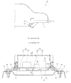
- FIG. 1 is a schematic side view showing a front section of a vehicle provided with a casing for housing an occupant protection device control unit according to an embodiment of the present disclosure.
- FIG. 2 is a sectional view taken along line II-II of FIG. 1 .
- FIG. 5 is an explanatory drawing illustrating a state where a lock portion is locked in a casing shown in FIG. 4 .
- FIG. 6 is an explanatory drawing illustrating a state in which a floor panel comes into contact with a casing shown in FIG. 5 from a lower front of a vehicle.
- the base 40 is an integral molding consisting of a flat center section 41 that is substantially rectangular in plan view, a frame section 42 that surrounds the center section 41 , and a flat edge section 43 that surrounds the frame section 42 .
- the frame section 42 extends upward from an edge of the center section 41 and has its upper end surface 42 a formed to have a flat surface.
- the upper end surface 42 a is parallel to the center section 41 .
- the edge section 43 is formed to be parallel to and be leveled with the center section 41 .
- the edge section 43 has a vertical plate-like front wall 45 (front extension part 45 ) formed at a front end thereof, which extends upward from the entire extent of the front end.
- the edge section 43 has a vertical plate-like rear wall 46 formed at a rear end thereof, which extends upward from the entire extent of the rear end.
- a front groove 47 is provided between a front end of the frame section 42 and the front wall 45 .
- a rear groove 48 is provided between a rear end of the frame section 42 and the rear wall 46 .
- the front wall 45 and the rear wall 46 are leveled with an upper end surface 42 a of the frame section 42 .
- the casing 20 is composed of the main body 70 having its bottom opened and the base 40 that covers the bottom surface of the main body 70 .
- the substrate 31 is secured to the main body 70 with the screws 71 , together with the base 40 located therebelow.
- the main body 70 has a skirt 72 formed integrally therewith at its bottom edge, which extends downward along its entire circumference.
- the skirt 72 covers the entire outer circumference of the frame section 42 .
- each of the front groove 47 and rear groove 48 has the skirt 72 put thereinto from above.
- the front and rear sides of the casing 20 are configured to be water-proof through the grooves 47 , 48 and the skirt 72 , thereby more providing a water-proof performance.
- the base 40 has a lock portion 80 that is deformable according to a deformation of the vehicle body 11 caused by a collision load fc from a vehicle front.
- the lock portion 80 when deformed, causes a front end of the base 40 to be locked with at least a part of a front wall 73 of the main body 70 .
- the front wall 73 of the main body 70 is composed of, for example, a front portion of the skirt 72 .
- the lock portion 80 is composed of the front wall 45 extending upward from a front end surface of the edge section 43 in the base 40 and a front portion 42 b of the frame section 42 in the base 40 .
- the front wall 45 is referred to as “front extension portion 45 extending upward from a front portion of the base 40 ”.
- the front portion 42 b in the frame section 42 is referred to as “rear extension portion 42 b extending upward from a front portion of the base 40 ”.
- the lock portion 80 is composed of the front and rear extension portions 45 , 42 b extending upward from a front portion of the base 40 .
- the front extension portion 45 is located so as to cover at least a part of the front wall 73 of the main body 70 from a vehicle front.
- the rear extension portion 42 b and the front extension portion 45 are located so as to be able to longitudinally put the front wall 73 of the main body 70 therebetween.
- the lock portion 80 when deformed by a collision load fc, causes a front end of the base 40 to be locked with at least a part of the front wall 73 of the main body 70 , thereby allowing the collision load fc to be dispersed from the front end of the base 40 to the front wall 73 of the main body 70 .
- the base 40 has only the lock portion 80 , which helps prevent the casing 20 from growing in size.
- the dispersion of the collision load fc in the front end of the base 40 to the front wall 73 of the main body 70 limits the deformation of the base 40 and the main body 70 .
- the occupant protection device control unit 30 has various important data stored therein. Such enhanced protection of the occupant protection device control unit 30 ensures that the various data are read out from the occupant protection device control unit 30 .
- the lock portion 80 puts the front wall 73 of the main body 70 between the front and rear extension portions 45 , 42 b extending upward from the front portion of the base 40 and thereby locks the front end of the base 40 with at least a part of the front wall 73 of the main body 70 .
- the lock portion 80 is simple and compact because the front and rear extension portions 45 , 42 b just extend upward from the front portion of the base 40 .
- the portion 11 a further deforms and presses the front extension portion 45 of the base 40 in the rearward and upward direction (indicated by arrow A 1 of FIG. 6 ), thereby causing the first bracket 51 to be torn off. This protects the occupant protection device control unit 30 (see FIG. 2 ) in the casing against the collision load fc.
- the portion 11 a further deforms and presses the front extension portion 45 of the base 40 in the rearward direction (indicated by arrow A 2 of FIG. 7 ), thereby causing the first bracket 51 to be deformed or torn off. This protects the occupant protection device control unit 30 (see FIG. 2 ) in the casing against the collision load fc.
- FIG. 8 shows an example of modifications to the main body 70 .
- the main body 70 has a waterproof cover 75 that covers the front extension portion 45 from top to a front face.
- the waterproof cover 75 prevents water Wa from entering the casing 20 when the main body 70 is exposed to water Wa.
- the casing 20 according to the present disclosure is suitable for use in the casing for housing the occupant protection device control unit 30 provided with an acceleration sensor.
Landscapes
- Engineering & Computer Science (AREA)
- Mechanical Engineering (AREA)
- Casings For Electric Apparatus (AREA)
- Vehicle Step Arrangements And Article Storage (AREA)
Applications Claiming Priority (2)
| Application Number | Priority Date | Filing Date | Title |
|---|---|---|---|
| JP2013116084A JP6012547B2 (ja) | 2013-05-31 | 2013-05-31 | 乗員保護装置制御ユニット収納用のケース |
| JP2013-116084 | 2013-05-31 |
Publications (2)
| Publication Number | Publication Date |
|---|---|
| US8899370B1 true US8899370B1 (en) | 2014-12-02 |
| US20140354123A1 US20140354123A1 (en) | 2014-12-04 |
Family
ID=51948268
Family Applications (1)
| Application Number | Title | Priority Date | Filing Date |
|---|---|---|---|
| US14/291,071 Active US8899370B1 (en) | 2013-05-31 | 2014-05-30 | Casing for housing occupant protection device control unit |
Country Status (2)
| Country | Link |
|---|---|
| US (1) | US8899370B1 (https=) |
| JP (1) | JP6012547B2 (https=) |
Cited By (6)
| Publication number | Priority date | Publication date | Assignee | Title |
|---|---|---|---|---|
| US20160157364A1 (en) * | 2007-12-20 | 2016-06-02 | Trw Automotive U.S. Llc | Electronic assembly and method of manufacturing same |
| CN106427860A (zh) * | 2016-11-08 | 2017-02-22 | 刘昭辰 | 一种汽车防水应急系统 |
| US20170210307A1 (en) * | 2016-01-22 | 2017-07-27 | Toyota Motor Engineering & Manufacturing North America, Inc. | Attachment for electrical components |
| US20180263136A1 (en) * | 2017-03-11 | 2018-09-13 | Microsoft Technology Licensing, Llc | Flexible or rotatable connectors in electronic devices |
| EP3578421A1 (en) * | 2018-06-07 | 2019-12-11 | Yazaki Corporation | Liquid-proof structure of fitting body, electrical connection box, and wire harness |
| US20220348157A1 (en) * | 2021-04-30 | 2022-11-03 | Denso Ten Limited | Control device |
Families Citing this family (3)
| Publication number | Priority date | Publication date | Assignee | Title |
|---|---|---|---|---|
| CN109076711B (zh) * | 2016-04-28 | 2021-02-02 | 康奈可关精株式会社 | 车载支架及将箱体组装于车载支架而成的单元 |
| JP6192769B1 (ja) * | 2016-04-28 | 2017-09-06 | カルソニックカンセイ株式会社 | 車載ブラケット、および車載ブラケットに筐体を組み付けたユニット |
| CN111231912B (zh) * | 2020-02-18 | 2021-05-14 | 寿光市顺凯机械有限公司 | 一种安全性高的汽车底盘 |
Citations (3)
| Publication number | Priority date | Publication date | Assignee | Title |
|---|---|---|---|---|
| US7510404B2 (en) * | 2003-11-27 | 2009-03-31 | Fujitsu Ten Limited | Fixing structure and control device using that fixing structure |
| JP2010083382A (ja) | 2008-09-30 | 2010-04-15 | Fujitsu Ten Ltd | 筐体固定構造 |
| US8414013B2 (en) * | 2009-04-03 | 2013-04-09 | Fujitsu Ten Limited | Housing structure for in-vehicle electronic device |
Family Cites Families (3)
| Publication number | Priority date | Publication date | Assignee | Title |
|---|---|---|---|---|
| JP2010215127A (ja) * | 2009-03-17 | 2010-09-30 | Fujitsu Ten Ltd | 車載用電子機器 |
| JP2010241387A (ja) * | 2009-04-09 | 2010-10-28 | Fujitsu Ten Ltd | 車載用電子機器の筐体構造 |
| JP5110130B2 (ja) * | 2010-07-27 | 2012-12-26 | 株式会社デンソー | 車載電子制御ユニット用筺体 |
-
2013
- 2013-05-31 JP JP2013116084A patent/JP6012547B2/ja not_active Expired - Fee Related
-
2014
- 2014-05-30 US US14/291,071 patent/US8899370B1/en active Active
Patent Citations (4)
| Publication number | Priority date | Publication date | Assignee | Title |
|---|---|---|---|---|
| US7510404B2 (en) * | 2003-11-27 | 2009-03-31 | Fujitsu Ten Limited | Fixing structure and control device using that fixing structure |
| JP2010083382A (ja) | 2008-09-30 | 2010-04-15 | Fujitsu Ten Ltd | 筐体固定構造 |
| US8096576B2 (en) | 2008-09-30 | 2012-01-17 | Fujitsu Ten Limited | Housing fixing structure |
| US8414013B2 (en) * | 2009-04-03 | 2013-04-09 | Fujitsu Ten Limited | Housing structure for in-vehicle electronic device |
Cited By (8)
| Publication number | Priority date | Publication date | Assignee | Title |
|---|---|---|---|---|
| US20160157364A1 (en) * | 2007-12-20 | 2016-06-02 | Trw Automotive U.S. Llc | Electronic assembly and method of manufacturing same |
| US9756741B2 (en) * | 2007-12-20 | 2017-09-05 | Trw Automotive U.S. Llc | Electronic assembly and method of manufacture same |
| US20170210307A1 (en) * | 2016-01-22 | 2017-07-27 | Toyota Motor Engineering & Manufacturing North America, Inc. | Attachment for electrical components |
| CN106427860A (zh) * | 2016-11-08 | 2017-02-22 | 刘昭辰 | 一种汽车防水应急系统 |
| US20180263136A1 (en) * | 2017-03-11 | 2018-09-13 | Microsoft Technology Licensing, Llc | Flexible or rotatable connectors in electronic devices |
| EP3578421A1 (en) * | 2018-06-07 | 2019-12-11 | Yazaki Corporation | Liquid-proof structure of fitting body, electrical connection box, and wire harness |
| US20220348157A1 (en) * | 2021-04-30 | 2022-11-03 | Denso Ten Limited | Control device |
| US12024107B2 (en) * | 2021-04-30 | 2024-07-02 | Denso Ten Limited | Control device |
Also Published As
| Publication number | Publication date |
|---|---|
| JP2014234053A (ja) | 2014-12-15 |
| JP6012547B2 (ja) | 2016-10-25 |
| US20140354123A1 (en) | 2014-12-04 |
Similar Documents
| Publication | Publication Date | Title |
|---|---|---|
| US8899370B1 (en) | Casing for housing occupant protection device control unit | |
| US9320156B2 (en) | Mounting structure for casing of occupant protection device control unit | |
| US8096576B2 (en) | Housing fixing structure | |
| US8387457B2 (en) | Collision sensor housing and module | |
| US8830686B2 (en) | In-vehicle electronic control unit housing | |
| US10837807B2 (en) | Sensor mount structure | |
| US10766430B2 (en) | Autonomous rear viewing sensor mount | |
| CN105180984B (zh) | 用于卡扣配合安装碰撞传感器的设备 | |
| US10399522B2 (en) | Mounting structure of vehicle periphery monitoring device | |
| US11059430B2 (en) | Sensor mount structure | |
| US10201108B2 (en) | Electronic control apparatus for vehicle | |
| US9738237B2 (en) | In-vehicle device covering structure | |
| US20070273166A1 (en) | System for detecting objects colliding with automotive vehicle | |
| JP2015050337A (ja) | 筐体の被水防止構造 | |
| JP6588202B2 (ja) | 電子装置 | |
| JP5648886B2 (ja) | 車両用電子制御装置の取付構造 | |
| US6676156B2 (en) | Electronic impact sensor mounted on supporting member | |
| KR101518724B1 (ko) | 전자 장치의 안정된 연결을 위한 구조체 | |
| CN110893825A (zh) | 外界传感器安装构造 | |
| JP6555003B2 (ja) | フェンダー構造 | |
| JP5270649B2 (ja) | 乗員拘束装置用の制御装置 | |
| US20070034439A1 (en) | Safety device for a motor vehicle | |
| JP2025156990A (ja) | 撮像装置 | |
| JP6573165B2 (ja) | カバーの取付構造 | |
| JP2021070328A (ja) | 車載センサ搭載構造 |
Legal Events
| Date | Code | Title | Description |
|---|---|---|---|
| AS | Assignment |
Owner name: HONDA MOTOR CO., LTD., JAPAN Free format text: ASSIGNMENT OF ASSIGNORS INTEREST;ASSIGNORS:OHMOTO, TAKAHIRO;OKAMURA, KENYU;ISHIKAWA, TAKAHIRO;AND OTHERS;SIGNING DATES FROM 20140515 TO 20140520;REEL/FRAME:032994/0194 |
|
| STCF | Information on status: patent grant |
Free format text: PATENTED CASE |
|
| MAFP | Maintenance fee payment |
Free format text: PAYMENT OF MAINTENANCE FEE, 4TH YEAR, LARGE ENTITY (ORIGINAL EVENT CODE: M1551) Year of fee payment: 4 |
|
| MAFP | Maintenance fee payment |
Free format text: PAYMENT OF MAINTENANCE FEE, 8TH YEAR, LARGE ENTITY (ORIGINAL EVENT CODE: M1552); ENTITY STATUS OF PATENT OWNER: LARGE ENTITY Year of fee payment: 8 |