US8866882B2 - Stereoscopic image format transformation method applied to display system - Google Patents
Stereoscopic image format transformation method applied to display system Download PDFInfo
- Publication number
- US8866882B2 US8866882B2 US11/822,226 US82222607A US8866882B2 US 8866882 B2 US8866882 B2 US 8866882B2 US 82222607 A US82222607 A US 82222607A US 8866882 B2 US8866882 B2 US 8866882B2
- Authority
- US
- United States
- Prior art keywords
- stereoscopic image
- aspect ratio
- format
- panel
- edge
- Prior art date
- Legal status (The legal status is an assumption and is not a legal conclusion. Google has not performed a legal analysis and makes no representation as to the accuracy of the status listed.)
- Active, expires
Links
- 238000011426 transformation method Methods 0.000 title claims abstract description 5
- 230000001131 transforming effect Effects 0.000 claims abstract description 10
- 238000000034 method Methods 0.000 claims description 23
- 238000010586 diagram Methods 0.000 description 22
- 230000009466 transformation Effects 0.000 description 7
- 239000011521 glass Substances 0.000 description 5
- 230000010287 polarization Effects 0.000 description 5
- 230000000007 visual effect Effects 0.000 description 5
- 235000015096 spirit Nutrition 0.000 description 2
- 230000004075 alteration Effects 0.000 description 1
- 210000004556 brain Anatomy 0.000 description 1
- 239000004973 liquid crystal related substance Substances 0.000 description 1
- 238000004519 manufacturing process Methods 0.000 description 1
- 238000012986 modification Methods 0.000 description 1
- 230000004048 modification Effects 0.000 description 1
Images


Classifications
-
- H04N13/0029—
-
- H—ELECTRICITY
- H04—ELECTRIC COMMUNICATION TECHNIQUE
- H04N—PICTORIAL COMMUNICATION, e.g. TELEVISION
- H04N13/00—Stereoscopic video systems; Multi-view video systems; Details thereof
- H04N13/10—Processing, recording or transmission of stereoscopic or multi-view image signals
- H04N13/106—Processing image signals
- H04N13/139—Format conversion, e.g. of frame-rate or size
-
- H—ELECTRICITY
- H04—ELECTRIC COMMUNICATION TECHNIQUE
- H04N—PICTORIAL COMMUNICATION, e.g. TELEVISION
- H04N7/00—Television systems
- H04N7/01—Conversion of standards, e.g. involving analogue television standards or digital television standards processed at pixel level
- H04N7/0117—Conversion of standards, e.g. involving analogue television standards or digital television standards processed at pixel level involving conversion of the spatial resolution of the incoming video signal
- H04N7/012—Conversion between an interlaced and a progressive signal
-
- H—ELECTRICITY
- H04—ELECTRIC COMMUNICATION TECHNIQUE
- H04N—PICTORIAL COMMUNICATION, e.g. TELEVISION
- H04N7/00—Television systems
- H04N7/01—Conversion of standards, e.g. involving analogue television standards or digital television standards processed at pixel level
- H04N7/0117—Conversion of standards, e.g. involving analogue television standards or digital television standards processed at pixel level involving conversion of the spatial resolution of the incoming video signal
- H04N7/0122—Conversion of standards, e.g. involving analogue television standards or digital television standards processed at pixel level involving conversion of the spatial resolution of the incoming video signal the input and the output signals having different aspect ratios
Definitions
- This invention relates to a stereoscopic image transformation method and, more particularly, relates to a method for transforming a non-interlace format of a stereoscopic image into an interlace format.
- a 3D stereoscopic image is formed by combining two sets of image data in different visual angles, wherein one set of image data corresponds to left-eye visual angle, and the other set of image data corresponds to right-eye visual angle.
- one set of image data corresponds to left-eye visual angle
- the other set of image data corresponds to right-eye visual angle.
- FIG. 1A is a schematic diagram illustrating an anaglyph stereoscopic image.
- FIG. 1B is an external view illustrating a pair of glasses for seeing an anaglyph stereoscopic image.
- the anaglyph theory is applied to the stereoscopic image.
- a normal image is divided into the left-eye and the right-eye image data.
- red or blue color in the left-eye or right-eye image data is respectively filtered off.
- a stereoscopic image is formed by interlacing those two image data being processed before.
- FIG. 1B a viewer needs to wear a pair of glasses with one red and one blue eyeglass, so as to enable his left eye and right eye to see respective color image. Consequently, the viewer will see a stereoscopic image.
- Another technique utilizes a polarizer to generate two different polarizations, such that an image can be divided into left-eye and right-eye image data.
- the polarizers can be attached onto each lens of two projectors respectively, such that the light emitted from one projector differs from the other one by 90 degrees. Then, by using a screen capable of keeping the polarization of light, the viewer can wear a pair of glasses having eyeglasses with two different polarizations to see a stereoscopic image.
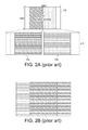
- FIG. 2A is a schematic diagram illustrating a stereoscopic image 10 with a side-by-side format being transformed into an interlace format.
- the panel 12 is an interlaced panel
- the aspect ratio of the panel 12 is 16:10 (the resolution is 1680*1050)
- the aspect ratio of the stereoscopic image 10 is 4:3.
- the left part of the image 10 on the panel 12 will be extended to a width of 1680 and be transformed into odd scanning lines as image 10 a shown in FIG. 2A .
- the right part of image 10 on the panel 12 will also be extended to a width of 1680 and be transformed into even scanning lines as image 10 b shown in FIG. 2A .
- the odd and even scanning lines can be interlaced to form a stereoscopic image.
- FIG. 2B is a schematic diagram illustrating an interlace format of the stereoscopic image 10 .
- a completely stereoscopic image can not be formed by interlacing the left-eye and right-eye image data, because it will make the viewer uncomfortable.
- FIG. 3A is a schematic diagram illustrating a stereoscopic image 14 with an above-and-below format being transformed into an interlace format.
- the panel 16 is an interlaced panel
- the aspect ratio of the panel 16 is 16:10 (the resolution is 1680*1050)
- the aspect ratio of the stereoscopic image 14 is 16:9.
- the upper part of the image 14 on the panel 16 will be extended to a height of 1050 and be transformed into odd scanning lines as image 14 a shown in FIG. 3A .
- the lower part of the image 14 on the panel 16 will also be extended to a height of 1050 and be transformed into even scanning lines as image 14 b shown in FIG. 3A . Finally, the odd and even scanning lines can be interlaced to form a stereoscopic image.
- FIG. 3B is a schematic diagram illustrating an interlace format of the stereoscopic image 14 .
- a completely stereoscopic image can not be formed by interlacing the left-eye and right-eye image data, because it will make the viewer uncomfortable.
- the main scope of the invention is to provide a method for transforming a non-interlace format of the stereoscopic image into an interlace format, so as to solve the aforesaid problems.
- a scope of the invention is to provide a method for transforming a format of a stereoscopic image by interlacing a left-eye image data and a right-eye image data of the stereoscopic image according to the format of the stereoscopic image, a first aspect ratio of the panel, and a second aspect ratio of the stereoscopic image, so as to form a completely interlaced stereoscopic image.
- the method of the invention is used for transforming a non-interlace format of a stereoscopic image into an interlace format.
- a panel of the display system has a first aspect ratio, and the stereoscopic image with a second aspect ratio comprises a left-eye image data and a right-eye image data.
- the method of the invention comprises the following steps.
- the stereoscopic image is received. Afterward, whether the second aspect ratio of the stereoscopic image is equal to the first aspect ratio of the panel is judged, and if it is YES, the non-interlace format of the stereoscopic image is transformed into the interlace format in a general manner; otherwise, the left-eye image data and the right-eye image data of the stereoscopic image are interlaced according to the non-interlace format of the stereoscopic image, the first aspect ratio of the panel, and the second aspect ratio of the stereoscopic image, so as to form a completely interlaced stereoscopic image.
- the method of the invention transforms the non-interlace format of the stereoscopic image into the interlace format according to the format of the stereoscopic image, the aspect ratio of the panel, and the aspect ratio of the stereoscopic image.
- the invention can correct an image without affecting the aspect ratio of the image, so as to form a completely interlaced stereoscopic image.
- FIG. 1A is a schematic diagram illustrating an anaglyph stereoscopic image.
- FIG. 1B is an external view illustrating a pair of glasses for seeing an anaglyph stereoscopic image.
- FIG. 2A is a schematic diagram illustrating a stereoscopic image with a side-by-side format being transformed into an interlace format.
- FIG. 2B is a schematic diagram illustrating an interlace format of the stereoscopic image.
- FIG. 3A is a schematic diagram illustrating a stereoscopic image with an above-and-below format being transformed into an interlace format.
- FIG. 3B is a schematic diagram illustrating an interlace format of the stereoscopic image.
- FIG. 4 is a functional block diagram illustrating a display system according to a preferred embodiment of the invention.
- FIG. 5A is a schematic diagram illustrating the stereoscopic image with a side-by-side format being transformed into an interlace format.
- FIG. 5B is a flow chart judging whether the aspect ratio of the stereoscopic image is equal to the aspect ratio of the panel according to the invention.
- FIG. 5C is a flow chart showing a side-by-side format of the stereoscopic image being transformed into an interlace format according to the invention.
- FIG. 5D is a schematic diagram illustrating a completely interlaced stereoscopic image being formed by the method of the invention.
- FIG. 6A is a schematic diagram illustrating the stereoscopic image with an above-and-below format being transformed into an interlace format.
- FIG. 6B is a schematic diagram illustrating a completely interlaced stereoscopic image being formed by the method of the invention.
- FIG. 7 is a functional block diagram illustrating a transformation apparatus according to a preferred embodiment of the invention.
- FIG. 4 is a functional block diagram illustrating a display system 3 according to a preferred embodiment of the invention.
- the display system 3 comprises a decoder 30 , a scaler 32 , a transformation apparatus 34 , and a panel 36 with a first aspect ratio.
- the decoder 30 is used for receiving and decoding a stereoscopic image 5 .
- the stereoscopic image 5 with a non-interlace format and a second aspect ratio comprises a left-eye image data and a right image data.
- the scaler 32 is used for scaling the stereoscopic image 5 to comply with the native resolution of the panel 36 .
- the transformation apparatus 34 is used for transforming the non-interlace format of the stereoscopic image 5 into an interlace format.
- the interlace format of the stereoscopic image 5 can be a side-by-side format or an above-and-below format. Some examples will be taken to explain how the invention transforms the side-by-side format or the above-and-below format into the interlace format.
- FIG. 5A is a schematic diagram illustrating the stereoscopic image 5 with a side-by-side format being transformed into an interlace format.
- the panel 36 is an interlaced panel
- the aspect ratio of the panel is, but not limited to, 16:10 (the resolution is 1680*1050)
- the aspect ratio of the stereoscopic image 5 is, but not limited to, 4:3.
- FIG. 5B is a flow chart judging whether the aspect ratio of the stereoscopic image 5 is equal to the aspect ratio of the panel 36 according to the invention.
- the method of the invention will judge whether the aspect ratio of the stereoscopic image 5 is equal to the aspect ratio of the panel 36 .
- step S 100 is performed to determine a first edge 50 , a second edge 52 , and a boundary 54 of the stereoscopic image 5 according to the aspect ratio (16:10) of the panel 36 and the aspect ratio (4:3) of the stereoscopic image 5 .
- step S 102 is performed to find out all pixels on the panel 36 excluding an area between the first edge 50 and the second edge 52 (i.e. all pixels in the areas A 1 and A 2 are shown in FIG. 5A ), wherein each pixel comprises N color components and N gray levels, each gray level corresponds to one of the N color components, and N is a natural number.
- each pixel comprises three color components, i.e. RGB.
- Step S 104 is then performed to judge whether the maximum of the three gray levels of each pixel in areas A 1 and A 2 (as shown in FIG. 5A ) is larger than a first threshold, wherein the first threshold can be set based on practical applications.
- the first threshold can be set as a gray level equal to 15.
- Step S 106 is then performed to count the number of pixels with the maximum gray level larger than the first threshold.
- step S 108 is performed to judge whether the number of pixels counted in the step S 106 is larger than a second threshold. If the number is smaller than the second threshold, the aspect ratio of the stereoscopic image 5 is not equal to the aspect ratio of the panel 36 .
- the second threshold can be set based on practical applications. For example, the second threshold can be set as 15.
- FIG. 5C is a flow chart showing a side-by-side format of the stereoscopic image 5 being transformed into an interlace format according to the invention.
- FIG. 5D is a schematic diagram illustrating a completely interlaced stereoscopic image being formed by the method of the invention.
- the method of the invention will transform the side-by-side format of the stereoscopic image 5 into the interlace format according to the format (side-by-side) of the stereoscopic image 5 , the aspect ratio (16:10) of the panel 36 , and the aspect ratio (4:3) of the stereoscopic image 5 .
- step S 200 is performed to transform the left-eye image data (i.e. the area L shown in FIG. 5A ) of the stereoscopic image 5 into a plurality of first scanning lines L 1 according to the side-by-side format, the first edge 50 , and the boundary 54 of the stereoscopic image 5 .
- step S 202 is performed to transform the right-eye image data (i.e. the area R shown in FIG. 5A ) of the stereoscopic image 5 into a plurality of second scanning lines R 1 according to the side-by-side format, the second edge 52 , and the boundary 54 of the stereoscopic image 5 .
- step S 204 is performed to interlace all first scanning lines L 1 and all second scanning lines R 1 to form a completely interlaced stereoscopic image, as shown in FIG. 5D .
- step S 202 can be performed first, followed by step S 200 .
- FIG. 6A is a schematic diagram illustrating the stereoscopic image 5 with an above-and-below format being transformed into an interlace format.
- the panel 36 is an interlaced panel
- the aspect ratio of the panel is, but not limited to, 16:10 (the resolution is 1680*1050)
- the aspect ratio of the stereoscopic image 5 is, but not limit to, 16:9.
- the method of the invention will judge whether the aspect ratio of the stereoscopic image 5 is equal to the aspect ratio of the panel 36 .
- a first edge 50 , a second edge 52 , and a boundary 54 of the stereoscopic image 5 are determined according to the aspect ratio (16:10) of the panel 36 and the aspect ratio (16:9) of the stereoscopic image 5 .
- all pixels on the panel 36 are found out excluding an area between the first edge 50 and the second edge 52 (i.e. all pixels in the areas A 1 and A 2 shown in FIG. 6A ).
- the first threshold can be set based on practical applications.
- the first threshold can be set as gray level equal to 15.
- the number of pixels with the maximum gray level larger than the first threshold is counted.
- the second threshold can be set based on practical applications. For example, the second threshold can be set as 15.
- FIG. 6B is a schematic diagram illustrating a completely interlaced stereoscopic image being formed by the method of the invention.
- the method of the invention will transform the above-and-below format of the stereoscopic image 5 into the interlace format according to the format (above-and-below) of the stereoscopic image 5 , the aspect ratio (16:10) of the panel, and the aspect ratio (16:9) of the stereoscopic image 5 .
- the left-eye image data (i.e. the area L shown in FIG. 6A ) of the stereoscopic image 5 is transformed into a plurality of first scanning lines L 1 according to the above-and-below format, the first edge 50 , and the boundary 54 of the stereoscopic image 5 .
- the right-eye image data (i.e. the area R shown in FIG. 6A ) of the stereoscopic image 5 is transformed into a plurality of second scanning lines R 1 according to the above-and-below format, the second edge 52 , and the boundary 54 of the stereoscopic image 5 .
- all first scanning lines L 1 and all second scanning lines R 1 are interlaced to form a completely interlaced stereoscopic image, as shown in FIG. 6B .
- FIG. 7 is a functional block diagram illustrating a transformation apparatus 34 according to a preferred embodiment of the invention.
- the transformation apparatus 34 comprises a processing unit 340 , a first judging unit 342 , a second judging unit 344 , and a transformation unit 346 .
- the processing unit 340 transmits the stereoscopic image 5 with a side-by-side format to the first judging unit 342 , or transmits the stereoscopic image 5 with an above-and-below format to the second judging unit 344 .
- the first judging unit 342 judges whether the aspect ratio of the stereoscopic image 5 with the side-by-side format is equal to the aspect ratio of the panel 36 .
- the second judging unit 344 judges whether the aspect ratio of the stereoscopic image 5 with the above-and-below format is equal to the aspect ratio of the panel 36 .
- the transformation unit 346 interlaces the left-eye image data and the right-eye image data of the stereoscopic image 5 to form a completely interlaced stereoscopic image according to the format (side-by-side or above-and-below) of the stereoscopic image 5 , the aspect ratio of the panel 36 , and the aspect ratio of the stereoscopic image 5 . Accordingly, when the stereoscopic image is played repeatedly, a wrong image will not be formed when the aspect ratio (the resolution) of the panel is not equal to the stereoscopic image.
- the method of the invention can be used for transforming a non-interlace format of the stereoscopic image to an interlace format according to the format of the stereoscopic image, the aspect ratio of the panel, and the aspect ratio of the stereoscopic image.
- the method of the invention can be used to correct an image without affecting the aspect ratio, and a completely interlaced stereoscopic image is formed.
Landscapes
- Engineering & Computer Science (AREA)
- Multimedia (AREA)
- Signal Processing (AREA)
- Testing, Inspecting, Measuring Of Stereoscopic Televisions And Televisions (AREA)
- Liquid Crystal Display Device Control (AREA)
- Television Systems (AREA)
- Control Of Indicators Other Than Cathode Ray Tubes (AREA)
Applications Claiming Priority (3)
| Application Number | Priority Date | Filing Date | Title |
|---|---|---|---|
| TW95140867A | 2006-11-03 | ||
| TW095140867A TWI324477B (en) | 2006-11-03 | 2006-11-03 | Stereoscopic image format transformation method applied to display system |
| TW095140867 | 2006-11-03 |
Publications (2)
| Publication Number | Publication Date |
|---|---|
| US20080198218A1 US20080198218A1 (en) | 2008-08-21 |
| US8866882B2 true US8866882B2 (en) | 2014-10-21 |
Family
ID=39504149
Family Applications (1)
| Application Number | Title | Priority Date | Filing Date |
|---|---|---|---|
| US11/822,226 Active 2033-04-19 US8866882B2 (en) | 2006-11-03 | 2007-07-03 | Stereoscopic image format transformation method applied to display system |
Country Status (3)
| Country | Link |
|---|---|
| US (1) | US8866882B2 (ja) |
| JP (1) | JP4940397B2 (ja) |
| TW (1) | TWI324477B (ja) |
Cited By (1)
| Publication number | Priority date | Publication date | Assignee | Title |
|---|---|---|---|---|
| US10154251B2 (en) | 2015-12-21 | 2018-12-11 | Visteon Global Technologies, Inc. | Display assembly |
Families Citing this family (14)
| Publication number | Priority date | Publication date | Assignee | Title |
|---|---|---|---|---|
| US8478074B2 (en) * | 2006-07-07 | 2013-07-02 | Microsoft Corporation | Providing multiple and native representations of an image |
| US20090315981A1 (en) * | 2008-06-24 | 2009-12-24 | Samsung Electronics Co., Ltd. | Image processing method and apparatus |
| US20090315980A1 (en) * | 2008-06-24 | 2009-12-24 | Samsung Electronics Co., | Image processing method and apparatus |
| US20090317062A1 (en) * | 2008-06-24 | 2009-12-24 | Samsung Electronics Co., Ltd. | Image processing method and apparatus |
| KR20100002032A (ko) * | 2008-06-24 | 2010-01-06 | 삼성전자주식회사 | 영상 생성 방법, 영상 처리 방법, 및 그 장치 |
| US8629898B2 (en) * | 2008-09-03 | 2014-01-14 | Sony Corporation | Stereoscopic video delivery |
| US20100107126A1 (en) * | 2008-10-28 | 2010-04-29 | Hulu Llc | Method and apparatus for thumbnail selection and editing |
| US8773430B2 (en) * | 2009-12-09 | 2014-07-08 | Thomson Licensing | Method for distinguishing a 3D image from a 2D image and for identifying the presence of a 3D image format by feature correspondence determination |
| KR101691252B1 (ko) * | 2010-01-05 | 2016-12-29 | 리얼디 인크. | 타임 시퀀셜 액정 스테레오스코픽 디스플레이 시스템에서의 크로스토크 억제 |
| CN102238395A (zh) * | 2010-04-21 | 2011-11-09 | 深圳Tcl新技术有限公司 | 3d图像格式的运算方法以及采用该方法的3d电视机 |
| TWI400937B (zh) * | 2010-06-21 | 2013-07-01 | Acer Inc | 影像轉換裝置以及影像信號的轉換方法 |
| KR101279660B1 (ko) * | 2010-07-07 | 2013-06-27 | 엘지디스플레이 주식회사 | 입체영상 표시장치 및 그 구동방법 |
| TWI464666B (zh) * | 2012-05-03 | 2014-12-11 | Asustek Comp Inc | 顯示方法與可攜式裝置 |
| KR101392340B1 (ko) * | 2012-05-04 | 2014-05-07 | 엘지디스플레이 주식회사 | 입체영상 표시장치와 그 구동방법 |
Citations (9)
| Publication number | Priority date | Publication date | Assignee | Title |
|---|---|---|---|---|
| US6088052A (en) | 1997-01-08 | 2000-07-11 | Recherches Point Lab Inc. | 3D stereoscopic video display system |
| JP2001036871A (ja) | 1999-07-22 | 2001-02-09 | Matsushita Electric Ind Co Ltd | 画像供給装置および画像表示装置 |
| US20020011969A1 (en) | 2000-06-07 | 2002-01-31 | Lenny Lipton | Autostereoscopic pixel arrangement techniques |
| US20020163574A1 (en) | 2001-05-07 | 2002-11-07 | Divelbiss Adam W. | Aperture controlled flicker reduction for active stereoscopic glasses |
| JP2003289553A (ja) | 2002-03-28 | 2003-10-10 | Sanyo Electric Co Ltd | 映像データ処理装置及び立体映像表示システム |
| US20040218269A1 (en) * | 2002-01-14 | 2004-11-04 | Divelbiss Adam W. | General purpose stereoscopic 3D format conversion system and method |
| US6947097B1 (en) * | 1999-05-06 | 2005-09-20 | Thomson Licensing S.A. | Process for detecting black bars in a video image |
| US20060125916A1 (en) | 2002-11-07 | 2006-06-15 | Ken Mashitani | Three-dimensional video processing method and three-dimensional video display |
| US20060204239A1 (en) | 2005-03-10 | 2006-09-14 | Minoru Inaba | Digital stereo camera/digital stereo video camera, 3-dimensional display, 3-dimensional projector, and printer and stereo viewer |
Family Cites Families (3)
| Publication number | Priority date | Publication date | Assignee | Title |
|---|---|---|---|---|
| US608805A (en) * | 1898-08-09 | templin | ||
| JPH099293A (ja) * | 1995-06-20 | 1997-01-10 | Matsushita Electric Ind Co Ltd | 立体映像表示方法および立体映像データ作成方法 |
| JP4471979B2 (ja) * | 2004-11-08 | 2010-06-02 | シャープ株式会社 | 画像合成装置及び画像合成方法 |
-
2006
- 2006-11-03 TW TW095140867A patent/TWI324477B/zh active
-
2007
- 2007-07-03 US US11/822,226 patent/US8866882B2/en active Active
- 2007-07-18 JP JP2007187120A patent/JP4940397B2/ja active Active
Patent Citations (9)
| Publication number | Priority date | Publication date | Assignee | Title |
|---|---|---|---|---|
| US6088052A (en) | 1997-01-08 | 2000-07-11 | Recherches Point Lab Inc. | 3D stereoscopic video display system |
| US6947097B1 (en) * | 1999-05-06 | 2005-09-20 | Thomson Licensing S.A. | Process for detecting black bars in a video image |
| JP2001036871A (ja) | 1999-07-22 | 2001-02-09 | Matsushita Electric Ind Co Ltd | 画像供給装置および画像表示装置 |
| US20020011969A1 (en) | 2000-06-07 | 2002-01-31 | Lenny Lipton | Autostereoscopic pixel arrangement techniques |
| US20020163574A1 (en) | 2001-05-07 | 2002-11-07 | Divelbiss Adam W. | Aperture controlled flicker reduction for active stereoscopic glasses |
| US20040218269A1 (en) * | 2002-01-14 | 2004-11-04 | Divelbiss Adam W. | General purpose stereoscopic 3D format conversion system and method |
| JP2003289553A (ja) | 2002-03-28 | 2003-10-10 | Sanyo Electric Co Ltd | 映像データ処理装置及び立体映像表示システム |
| US20060125916A1 (en) | 2002-11-07 | 2006-06-15 | Ken Mashitani | Three-dimensional video processing method and three-dimensional video display |
| US20060204239A1 (en) | 2005-03-10 | 2006-09-14 | Minoru Inaba | Digital stereo camera/digital stereo video camera, 3-dimensional display, 3-dimensional projector, and printer and stereo viewer |
Non-Patent Citations (3)
| Title |
|---|
| Chinese language Taiwan Office Action dated Sep. 5, 2011. |
| English language translation of abstract of JP 2001-036871 (published Feb. 9, 2001). |
| English language translation of abstract of JP 2003-289553 (published Oct. 10, 2003). |
Cited By (1)
| Publication number | Priority date | Publication date | Assignee | Title |
|---|---|---|---|---|
| US10154251B2 (en) | 2015-12-21 | 2018-12-11 | Visteon Global Technologies, Inc. | Display assembly |
Also Published As
| Publication number | Publication date |
|---|---|
| TW200822703A (en) | 2008-05-16 |
| US20080198218A1 (en) | 2008-08-21 |
| JP2008118617A (ja) | 2008-05-22 |
| JP4940397B2 (ja) | 2012-05-30 |
| TWI324477B (en) | 2010-05-01 |
Similar Documents
| Publication | Publication Date | Title |
|---|---|---|
| US8866882B2 (en) | Stereoscopic image format transformation method applied to display system | |
| EP2699009B1 (en) | Stereoscopic display device with subpixel structures | |
| JP4637863B2 (ja) | 3d画像表示装置の画質の改善 | |
| US9812052B2 (en) | 2D/3D image displaying apparatus | |
| EP2285125A2 (en) | Display device, display method and computer program | |
| CN104539935B (zh) | 图像亮度的调节方法及调节装置、显示装置 | |
| TW201405483A (zh) | 影像資料處理方法以及使用該方法的立體影像顯示裝置 | |
| EP2541948B1 (en) | Stereoscopic image display method and display timing controller | |
| US8872902B2 (en) | Stereoscopic video processing device and method for modifying a parallax value, and program | |
| US20110279450A1 (en) | Three dimensional (3d) image display apparatus, and driving method thereof | |
| WO2011096280A1 (ja) | 画像表示装置、画像表示システム及び画像表示方法 | |
| CN110177267A (zh) | 一种平面led屏幕的3d效果显示方法 | |
| EP2595395A1 (en) | Display apparatus and driving method thereof | |
| US9137510B2 (en) | Image processing method, image processor and stereoscopic image display device using the image processor | |
| CN101198074B (zh) | 立体图像格式转换方法及应用该方法的显示系统 | |
| US20080094468A1 (en) | Method for displaying stereoscopic image and display system thereof | |
| KR101894090B1 (ko) | 멀티뷰 영상 생성방법과 이를 이용한 입체영상 표시장치 | |
| KR102126532B1 (ko) | 멀티뷰 영상 생성 방법과 이를 이용한 입체 영상 표시 장치 | |
| US9325980B2 (en) | 3D display panel and 3D display apparatus using the same and driving method thereof | |
| US20130063420A1 (en) | Stereoscopic Image Display Method, Stereoscopic Image Driving Method, and Stereoscopic Image Display System | |
| US9407907B2 (en) | Method and display for concurrently displaying a first image and a second image | |
| JPH07199143A (ja) | 液晶表示装置 | |
| KR101567710B1 (ko) | 특수 안경을 착용한 관찰자만 정보를 볼 수 있는 디스플레이 시스템 | |
| CN101794026A (zh) | 一种立体显示装置及立体显示方法 | |
| KR20040062251A (ko) | 3차원 영상 표시장치 |
Legal Events
| Date | Code | Title | Description |
|---|---|---|---|
| AS | Assignment |
Owner name: QUANTA COMPUTER INC., TAIWAN Free format text: ASSIGNMENT OF ASSIGNORS INTEREST;ASSIGNORS:LIU, YUN-CHENG;LEE, HSIN-HUNG;HUANG, YU-HSIANG;AND OTHERS;REEL/FRAME:019581/0366 Effective date: 20070615 |
|
| STCF | Information on status: patent grant |
Free format text: PATENTED CASE |
|
| MAFP | Maintenance fee payment |
Free format text: PAYMENT OF MAINTENANCE FEE, 4TH YEAR, LARGE ENTITY (ORIGINAL EVENT CODE: M1551) Year of fee payment: 4 |
|
| MAFP | Maintenance fee payment |
Free format text: PAYMENT OF MAINTENANCE FEE, 8TH YEAR, LARGE ENTITY (ORIGINAL EVENT CODE: M1552); ENTITY STATUS OF PATENT OWNER: LARGE ENTITY Year of fee payment: 8 |