US8858037B2 - Light emitting diode array illumination system with recycling - Google Patents
Light emitting diode array illumination system with recycling Download PDFInfo
- Publication number
- US8858037B2 US8858037B2 US13/403,172 US201213403172A US8858037B2 US 8858037 B2 US8858037 B2 US 8858037B2 US 201213403172 A US201213403172 A US 201213403172A US 8858037 B2 US8858037 B2 US 8858037B2
- Authority
- US
- United States
- Prior art keywords
- led
- illumination system
- light
- recycling
- recycling unit
- Prior art date
- Legal status (The legal status is an assumption and is not a legal conclusion. Google has not performed a legal analysis and makes no representation as to the accuracy of the status listed.)
- Active, expires
Links
Images


Classifications
-
- G—PHYSICS
- G03—PHOTOGRAPHY; CINEMATOGRAPHY; ANALOGOUS TECHNIQUES USING WAVES OTHER THAN OPTICAL WAVES; ELECTROGRAPHY; HOLOGRAPHY
- G03B—APPARATUS OR ARRANGEMENTS FOR TAKING PHOTOGRAPHS OR FOR PROJECTING OR VIEWING THEM; APPARATUS OR ARRANGEMENTS EMPLOYING ANALOGOUS TECHNIQUES USING WAVES OTHER THAN OPTICAL WAVES; ACCESSORIES THEREFOR
- G03B21/00—Projectors or projection-type viewers; Accessories therefor
- G03B21/14—Details
- G03B21/20—Lamp housings
- G03B21/2006—Lamp housings characterised by the light source
- G03B21/2033—LED or laser light sources
-
- F21K9/50—
-
- F—MECHANICAL ENGINEERING; LIGHTING; HEATING; WEAPONS; BLASTING
- F21—LIGHTING
- F21K—NON-ELECTRIC LIGHT SOURCES USING LUMINESCENCE; LIGHT SOURCES USING ELECTROCHEMILUMINESCENCE; LIGHT SOURCES USING CHARGES OF COMBUSTIBLE MATERIAL; LIGHT SOURCES USING SEMICONDUCTOR DEVICES AS LIGHT-GENERATING ELEMENTS; LIGHT SOURCES NOT OTHERWISE PROVIDED FOR
- F21K9/00—Light sources using semiconductor devices as light-generating elements, e.g. using light-emitting diodes [LED] or lasers
- F21K9/60—Optical arrangements integrated in the light source, e.g. for improving the colour rendering index or the light extraction
-
- F—MECHANICAL ENGINEERING; LIGHTING; HEATING; WEAPONS; BLASTING
- F21—LIGHTING
- F21V—FUNCTIONAL FEATURES OR DETAILS OF LIGHTING DEVICES OR SYSTEMS THEREOF; STRUCTURAL COMBINATIONS OF LIGHTING DEVICES WITH OTHER ARTICLES, NOT OTHERWISE PROVIDED FOR
- F21V5/00—Refractors for light sources
- F21V5/007—Array of lenses or refractors for a cluster of light sources, e.g. for arrangement of multiple light sources in one plane
-
- F—MECHANICAL ENGINEERING; LIGHTING; HEATING; WEAPONS; BLASTING
- F21—LIGHTING
- F21V—FUNCTIONAL FEATURES OR DETAILS OF LIGHTING DEVICES OR SYSTEMS THEREOF; STRUCTURAL COMBINATIONS OF LIGHTING DEVICES WITH OTHER ARTICLES, NOT OTHERWISE PROVIDED FOR
- F21V7/00—Reflectors for light sources
-
- F—MECHANICAL ENGINEERING; LIGHTING; HEATING; WEAPONS; BLASTING
- F21—LIGHTING
- F21V—FUNCTIONAL FEATURES OR DETAILS OF LIGHTING DEVICES OR SYSTEMS THEREOF; STRUCTURAL COMBINATIONS OF LIGHTING DEVICES WITH OTHER ARTICLES, NOT OTHERWISE PROVIDED FOR
- F21V7/00—Reflectors for light sources
- F21V7/04—Optical design
- F21V7/045—Optical design with spherical surface
-
- G—PHYSICS
- G03—PHOTOGRAPHY; CINEMATOGRAPHY; ANALOGOUS TECHNIQUES USING WAVES OTHER THAN OPTICAL WAVES; ELECTROGRAPHY; HOLOGRAPHY
- G03B—APPARATUS OR ARRANGEMENTS FOR TAKING PHOTOGRAPHS OR FOR PROJECTING OR VIEWING THEM; APPARATUS OR ARRANGEMENTS EMPLOYING ANALOGOUS TECHNIQUES USING WAVES OTHER THAN OPTICAL WAVES; ACCESSORIES THEREFOR
- G03B21/00—Projectors or projection-type viewers; Accessories therefor
- G03B21/14—Details
- G03B21/20—Lamp housings
- G03B21/208—Homogenising, shaping of the illumination light
-
- G—PHYSICS
- G03—PHOTOGRAPHY; CINEMATOGRAPHY; ANALOGOUS TECHNIQUES USING WAVES OTHER THAN OPTICAL WAVES; ELECTROGRAPHY; HOLOGRAPHY
- G03B—APPARATUS OR ARRANGEMENTS FOR TAKING PHOTOGRAPHS OR FOR PROJECTING OR VIEWING THEM; APPARATUS OR ARRANGEMENTS EMPLOYING ANALOGOUS TECHNIQUES USING WAVES OTHER THAN OPTICAL WAVES; ACCESSORIES THEREFOR
- G03B33/00—Colour photography, other than mere exposure or projection of a colour film
- G03B33/06—Colour photography, other than mere exposure or projection of a colour film by additive-colour projection apparatus
-
- G—PHYSICS
- G03—PHOTOGRAPHY; CINEMATOGRAPHY; ANALOGOUS TECHNIQUES USING WAVES OTHER THAN OPTICAL WAVES; ELECTROGRAPHY; HOLOGRAPHY
- G03B—APPARATUS OR ARRANGEMENTS FOR TAKING PHOTOGRAPHS OR FOR PROJECTING OR VIEWING THEM; APPARATUS OR ARRANGEMENTS EMPLOYING ANALOGOUS TECHNIQUES USING WAVES OTHER THAN OPTICAL WAVES; ACCESSORIES THEREFOR
- G03B33/00—Colour photography, other than mere exposure or projection of a colour film
- G03B33/10—Simultaneous recording or projection
- G03B33/12—Simultaneous recording or projection using beam-splitting or beam-combining systems, e.g. dichroic mirrors
-
- F21Y2101/02—
-
- F—MECHANICAL ENGINEERING; LIGHTING; HEATING; WEAPONS; BLASTING
- F21—LIGHTING
- F21Y—INDEXING SCHEME ASSOCIATED WITH SUBCLASSES F21K, F21L, F21S and F21V, RELATING TO THE FORM OR THE KIND OF THE LIGHT SOURCES OR OF THE COLOUR OF THE LIGHT EMITTED
- F21Y2115/00—Light-generating elements of semiconductor light sources
- F21Y2115/10—Light-emitting diodes [LED]
-
- G—PHYSICS
- G03—PHOTOGRAPHY; CINEMATOGRAPHY; ANALOGOUS TECHNIQUES USING WAVES OTHER THAN OPTICAL WAVES; ELECTROGRAPHY; HOLOGRAPHY
- G03B—APPARATUS OR ARRANGEMENTS FOR TAKING PHOTOGRAPHS OR FOR PROJECTING OR VIEWING THEM; APPARATUS OR ARRANGEMENTS EMPLOYING ANALOGOUS TECHNIQUES USING WAVES OTHER THAN OPTICAL WAVES; ACCESSORIES THEREFOR
- G03B21/00—Projectors or projection-type viewers; Accessories therefor
- G03B21/14—Details
- G03B21/20—Lamp housings
- G03B21/2006—Lamp housings characterised by the light source
- G03B21/2033—LED or laser light sources
- G03B21/204—LED or laser light sources using secondary light emission, e.g. luminescence or fluorescence
Definitions
- the present invention relates to a light illumination system and more particularly to an LED illumination system
- arc lamps capable of generating an output of 10,000 lumens or more are still considered to be the most cost effective light source.
- Laser is an alternative light source, but requires substantial price premium.
- Another possible alternative light source is a light emitting diode (LED) which can be an ideal candidate because the lifetime of more than 20,000 hours is several orders of magnitude greater than that of arc lamps, thereby resulting in lower operating cost.
- LED light emitting diode
- an LED is its low brightness compared to the arc lamps.
- An LED chip for example, may produce an output of less than 1,000 lumens.
- a high efficiency LED illumination system includes a plurality of LED modules and a plurality of corresponding collimating lenses to provide increased brightness.
- Each LED module has at least one LED element having a light emitting area that emits light and a recycling reflector.
- the reflector is positioned to reflect the light from the light emitting area back to the LED element and has a transmissive aperture through which the emitted light exits.
- the collimating lenses are arranged to receive and collimate the light exiting from the LED modules.
- FIG. 1 shows an LED module having a recycling reflector according an aspect of the present invention.
- FIG. 2 shows an LED recycling illumination unit having an array of LED modules and an array of corresponding collimating lenses according to an aspect of the present invention.
- FIG. 3A shows an alternative embodiment of an array of collimating lenses in the shape of a regular hexagon with rounded corners.
- FIG. 3B shows still another alternative embodiment of an array of collimating lenses in the shape of a regular hexagon with rounded corners in which the outer periphery of the array is circular in shape.
- FIG. 4 shows a schematic diagram of a projection system using an LED recycling illumination unit according to an aspect of the present invention.
- FIG. 5 shows a schematic diagram of a projection system using an LED recycling illumination unit according to another aspect of the present invention.
- FIG. 6 shows a schematic diagram of an alternative projection system using an LED recycling illumination unit according to an aspect of the present invention.
- FIGS. 7A and 7B show beam size changers for use with the projection system of FIG. 6 .
- FIG. 8 shows a schematic diagram of an LCD projection system using an LED recycling illumination unit according to an aspect of the present invention.
- FIG. 9 shows a schematic diagram of an LCOS projection system using an LED recycling illumination unit according to an aspect of the present invention.
- FIGS. 10A and 10B illustrate polarization recovery systems for use with the projection systems of FIGS. 8 and 9 .
- FIG. 1 shows an LED recycling module 18 which includes an LED module 4 , and a recycling reflector 6 such as a recycling collar positioned in front of an LED chip/element 10 .
- the recycling reflector 6 has a transmissive aperture 8 through which the LED light passes.
- a driver circuit 3 generates driving current to drive the LED chip/element 10 .
- the LED module 4 includes at least one LED chip 10 which is typically an LED element having a light emitting area that emits light and a substrate 12 on which the chip is attached.
- the emitting area includes an optional transparent window or lens 7 that protects the LED chip 10 and distributes light.
- the LED chip 10 can also have a phosphor coating for creating certain colors or white color.
- the heat sink 5 is attached to the substrate 12 to carry heat away from the LED chip 10 .
- Such LED modules 4 for example, are available from Luminus Devices, Inc. of Billerica, Mass.
- the LED chip 10 can be a single chip or multiple chips of white color, single color, or multiple color. For particular applications, they can be arranged such that the optical axis 16 of the transmissive aperture 8 of the recycling reflector 6 goes through the center of the LED chip's light emitting area which is also substantially at the proximity of the center of curvature of the recycling reflector.
- the LED elements 10 can emit light of a single color such as red, green and blue or emit white light through the coated phosphor. The emission angle is typically 180 degrees or less.
- the transmissive aperture 8 can be circular, rectangular, square, hexagonal or other shapes, depending on particular lighting applications.
- the recycling collar 6 is curved in a concave manner relative to the LED element 10 .
- the inner surface 14 is a reflective surface such that the LED light that impinges on the inner surface is reflected back to the light source, i.e., LED elements 10 .
- the reflective surface 14 can be provided by coating the exterior or interior surface of the collar 6 or by having a separate reflective mirror attached to the collar.
- the recycling collar 6 is spherical in shape relative to the center of the LED elements 10 such that the output is reflected back to itself with unit magnification.
- it is effectively an imaging system where the LED elements 10 form an image on to itself.
- substantially all LED light that impinges on the inner spherical reflective surface 14 is reflected back to the light source, i.e., emitting areas of the LED elements 10 .
- any LED light that does not pass through the transmissive aperture of a conventional illumination system is lost forever.
- the LED illumination system of the present invention allows recovery of a substantial amount of light that would have been lost. For example, in an illumination system whose transmissive aperture size captures about 20% of emitted light (i.e., 80% of the original light output is reflected back to the LED chip 10 for recycling), over 80% of brightness increase can be achieved. Using a 9 sq. mm.
- the etendue (light emitting area) white LED module (etendue of 30) with a total output of 2,250 lumens and using a 20% output coupled to the target without the recycling reflector, the etendue will have a value of 6 and an output of 450 lumens (2,250*20%) because 80% of the original light output would be lost. With a recycling gain of 80%, however, the output becomes 810 lumens (2250*20%+2250*20%*80%) with the same etendue of 6.
- the LED module 4 in the present invention can have a single LED element or an array of LEDs.
- the LED can be white, single color, or composed of multiple chips with single or multiple colors.
- the LED can also be a DC LED, or an AC LED.
- an LED recycling unit having an array 20 of LED recycling modules 18 and array 22 of corresponding collimating lenses 28 as shown in FIG. 2 can be used.
- the LED recycling module array 20 consists of seven LED recycling modules 18 that are closely positioned preferably in the same plane.
- each recycling module 18 has a light emitting area of 12 sq. mm. and the modules are closely positioned in a regular hexagonal manner with six outer modules surrounding one center module.
- regular hexagonal manner in the present invention means that the modules are arranged such that a line drawn through the center of each outer LED recycling module 18 defines a regular hexagon.
- An array 22 of seven corresponding collimating lenses 28 attached to a circular support plate 30 are positioned in front of the LED recycling modules 18 to collimate the light exiting the recycling modules.
- the optical axis of each collimating lens 28 is aligned with the optical axis 16 of a corresponding recycling module 18 for maximum efficiency.
- the support plate 30 is in turn attached to the common heat sink 24 .
- the LED recycling module array 20 is mounted on a common heat sink 24 with fins which removes heat generated from all of the LED modules 18 .
- the common heat sink 24 is in thermal communication, and preferably in contact, with the individual heat sinks 5 for all of the LED modules 4 .
- a fan 26 attached to the common heat sink 24 removes heat from the heat sink into the air.
- the collimating lenses 28 are shown as circular in shape. Since the apertures 8 of the recycling reflectors 6 should match the shape of the associated collimating lenses 28 for efficiency, the apertures should also be circular.
- the collimating lenses 28 and their associated apertures 8 of the recycling reflectors 6 are generally in the shape of a regular hexagon, i.e., all angles between any two adjacent sides are 120 degrees.
- the shape could be either strictly regular hexagon (both in collimating lenses 28 and associated apertures 8 ) or regular hexagon with rounded corners 38 (both in collimating lenses 28 and associated apertures 8 ).
- the rounded corners 38 can be circular in shape.
- the shape of both the collimating lenses 28 and associated apertures 8 can be in the shape of a regular hexagon.
- the periphery of the aperture 8 casts a shadow in the collimating lens 28 due to the relatively large light emitting area.
- the center collimating lens 28 is in the shape of a regular hexagon with rounded corners while the outer lenses are partially hexagonal and partially round. This may have the added benefit of decreasing the manufacturing cost as there is less number of cuts to be made.
- the lens array 22 can be made by polishing individual lenses, in one embodiment, the entire lens array can be made as a single piece by injection molding which substantially decreases the manufacturing cost.
- the lens array can be either molded glass or plastic depending on applications.
- an array of nineteen LED recycling modules 18 arranged in a regular hexagonal manner can also be used to generate even more brightness.
- a center recycling module is surrounded by six intermediate modules as in the previous embodiment and the six intermediate modules are in turn surrounded by twelve outermost modules such that a line drawn through the center of each outermost module defines a regular hexagon.
- an array of nineteen corresponding collimating lenses 28 are positioned in front of the LED recycling modules 18 .
- the shapes and arrangements of the lens 28 and aperture 8 for the seven LED recycling module array 20 also apply to the 19 LED recycling module array.
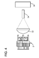
- FIG. 4 shows a schematic diagram of a projection system using an LED recycling illumination unit according to an aspect of the present invention.
- the projection system 40 includes a 7-LED recycling unit 2 , focusing lens 32 , light pipe 34 and a projection engine 36 such as a DLP engine.
- the collimated light output from the 7-LED recycling unit 2 is focused by the focusing lens 32 and is inputted to the light pipe 34 .
- the output of the light pipe 34 is then inputted to the projection engine 36 .
- the projection engine 36 projects still or moving images onto a screen (not shown).
- Table 1 below shows the potential projector output using the present invention of FIG. 4 .
- each LED recycling module 18 of the present invention outputs 1350 lumens, thereby yielding an output of 9450 lumens with an array of 7 LED recycling modules 18 .
- the projector output is 3308 lumens.
- FIG. 5 shows a schematic diagram of a projection system using an LED recycling illumination unit according to another aspect of the present invention. While the projection system 40 of FIG. 4 uses a single LED recycling module, the projection system 50 of FIG. 5 uses three separate LED recycling units 2 : red LED recycling unit 42 using an array of 7 red LED chips, green LED recycling unit 44 using an array of 7 green LED chips, and blue LED recycling unit 46 using an array of 7 blue LED chips.
- Filter combiner 48 passes red color from the red LED recycling unit 42 and blocks and reflects green color.
- Filter combiner 49 passes red and green colors from the red and green LED recycling units 42 , 44 , and blocks and reflects blue color.
- the combiners 48 and 49 combine red, green and blue colors and pass them to the focusing lens.
- each filter combiner is a cube prism which consists of two prisms and a filter therebetween.
- all sides of the cube prism are polished to act as a waveguide to efficiently transmit the collimated lights from the LED recycling units 42 - 46 with minimal loss.
- Table 2 below shows the potential projector output using the present invention of FIG. 5 .
- Figures in Table 2 are based on RGB LED chips from Osram Opto Semiconductors GmbH, Germany, 1.24 inch DLP chip and F/2.4 projector output lens. Without using the present invention, the output with 7 LED modules would be 12288.5 (3920 from red, 7371 from green and 997.5 from blue) and the final projector output would be 4301 lumens (35% of 12288.5).
- the output increases by 80%.
- the total output from the combination of red, green and blue LED recycling units 42-46 is 18486 lumens and the final projector output is 6470 lumens, which is a vast improvement over 4301 lumens without using the present invention.
- FIG. 6 shows a schematic diagram of an alternative projection system 60 using an LED recycling illumination unit 2 according to an aspect of the present invention.
- the illumination system 60 comprising the LED recycling unit 2 can be used for LCD (liquid crystal display) and LCOS (liquid crystal on silicon) projection systems 60 .
- LCD liquid crystal display
- LCOS liquid crystal on silicon
- the output parallel beam from the LED recycling unit 2 is directed to a reflective polarizer 52 which passes one polarization while reflecting the other polarization toward the recycling unit 2 , thereby further enhancing the recycling effect of the recycling unit 2 .
- the output of the reflective polarizer 52 is then directed to the LCD or LCOS projection engine 36 .
- the LED recycling unit 2 replaces the standard arc lamp as the illumination system.
- FIG. 7A shows a beam size changer 70 that decreases the cross-sectional size of the beam by a predetermined amount.
- FIG. 7B shows a beam size changer 72 that increases the cross-sectional size of the beam by a predetermined amount.
- FIG. 8 shows a schematic diagram of an LCD projection system 78 using an LED recycling illumination unit according to an aspect of the present invention.
- the illumination system of FIG. 8 uses three separate LED recycling units 42 - 46 outputting red, green and blue colors.
- the three LED recycling units 42 - 46 can also contain the size changing lens system 70 , 72 of FIGS. 7A-B as required.
- the projection system 78 also includes red, green, blue LCD imaging panels 80 , 82 , 84 and an x-cube 88 .
- the x-cube 88 combines illuminated images from the three imaging panels 80 - 84 and routes them to a projection lens system 86 .
- FIG. 9 shows a schematic diagram of an LCOS projection system 100 using an LED recycling illumination unit according to an aspect of the present invention.
- the LCOS projection system 100 includes three color LED recycling units 42 - 46 46 outputting red, green and blue colors.
- the three LED recycling units 42 - 46 can also contain the size changing lens system 70 , 72 of FIGS. 7A-B as required.
- the projection system 100 also includes red, green, blue LCOS imaging panels 90 , 92 , 94 , polarizing beam splitters (PBS) 96 , 97 , 98 and an x-cube 99 .
- the x-cube 99 combines illuminated images from the three imaging panels 90 - 94 and routes them to a projection lens system 86 .
- the PBS 97 is positioned behind the green LED recycling units 44 and the green LCOS imaging panel 92 is positioned behind the PBS 97 such that the collimated light from the green LED recycling unit is imaged by the green LCOS imaging panel and the imaged light is reflected into the x-cube 99 by the PBS 97 .
- FIGS. 10A and 10B can be added to each LED recycling unit 42 - 46 .
- FIG. 10A shows an embodiment with a reflective polarizer 52 and a wave plate 102 .
- the unused polarization is reflected back into the LED recycling unit 42 - 46 , which further increases the amount of recycling, thereby increasing the amount of polarized light output.
- the wave plate 102 is preferably a quarter wave plate such that the reflected light travels through the plate twice to turn the polarization of light by 90 degrees.
- FIG. 10B illustrates a polarization recovery system including a PBS array 102 and a fly-eye lens array 104 interposed between a LED recycling unit 42 - 46 and the PBS array.
- each LED module 18 used in the LED recycling units can have a single large emitting area, or have an array of smaller LEDs thus providing multiple light emitting areas.
- an array other than 7 LEDs can be used.
- an array of 2 or more LED recycling modules 18 can be used.
- a ring of LED modules is packed around a single LED module forming 7 LED array.
- One or more rings such as in a 19 LED module illumination system can be added further to increase the light output.
Priority Applications (1)
| Application Number | Priority Date | Filing Date | Title |
|---|---|---|---|
| US13/403,172 US8858037B2 (en) | 2011-02-23 | 2012-02-23 | Light emitting diode array illumination system with recycling |
Applications Claiming Priority (2)
| Application Number | Priority Date | Filing Date | Title |
|---|---|---|---|
| US201161445574P | 2011-02-23 | 2011-02-23 | |
| US13/403,172 US8858037B2 (en) | 2011-02-23 | 2012-02-23 | Light emitting diode array illumination system with recycling |
Publications (2)
| Publication Number | Publication Date |
|---|---|
| US20120212929A1 US20120212929A1 (en) | 2012-08-23 |
| US8858037B2 true US8858037B2 (en) | 2014-10-14 |
Family
ID=46652578
Family Applications (1)
| Application Number | Title | Priority Date | Filing Date |
|---|---|---|---|
| US13/403,172 Active 2033-04-14 US8858037B2 (en) | 2011-02-23 | 2012-02-23 | Light emitting diode array illumination system with recycling |
Country Status (6)
| Country | Link |
|---|---|
| US (1) | US8858037B2 (ja) |
| EP (1) | EP2678604A4 (ja) |
| JP (1) | JP6155200B2 (ja) |
| CN (1) | CN103502726A (ja) |
| TW (1) | TWI572821B (ja) |
| WO (1) | WO2012116139A1 (ja) |
Cited By (2)
| Publication number | Priority date | Publication date | Assignee | Title |
|---|---|---|---|---|
| US20160091784A1 (en) * | 2013-05-13 | 2016-03-31 | Appotronics China Corporation | Laser light source, wavelength conversion light source, light combining light source, and projection system |
| US10845027B2 (en) | 2018-09-13 | 2020-11-24 | Elation Lighting, Inc. | Sparkle effect lighting device |
Families Citing this family (17)
| Publication number | Priority date | Publication date | Assignee | Title |
|---|---|---|---|---|
| US9454004B2 (en) * | 2012-10-03 | 2016-09-27 | The United States Of America As Represented By The Secretary Of The Army | Apparatus for coherent beam combining in an array of laser collimators |
| JP6349784B2 (ja) * | 2013-03-14 | 2018-07-04 | 株式会社リコー | 光源ユニット並びに照明装置及び画像投射装置 |
| CN107632487B (zh) | 2013-04-20 | 2020-03-24 | 深圳光峰科技股份有限公司 | 发光装置及相关光源系统 |
| JP6232128B2 (ja) * | 2013-06-06 | 2017-11-15 | ドルビー ラボラトリーズ ライセンシング コーポレイション | オーディオ装置のためのライティング |
| CN103822140A (zh) * | 2014-02-12 | 2014-05-28 | 吴震 | 发光二极管光源、投影显示光源和投影显示光机 |
| CN103822141A (zh) * | 2014-02-12 | 2014-05-28 | 吴震 | 发光二极管光源、投影显示光源和投影显示光机 |
| KR101737321B1 (ko) * | 2015-03-23 | 2017-05-22 | (주)엔디에스 | 집광 조명장치 |
| JP6659240B2 (ja) * | 2015-06-01 | 2020-03-04 | 株式会社ユーテクノロジー | Led照明装置 |
| CN105135255A (zh) * | 2015-09-24 | 2015-12-09 | 长沙蓝锐知识产权咨询有限公司 | 一种多功能照明灯具 |
| JP6653450B2 (ja) | 2016-06-29 | 2020-02-26 | パナソニックIpマネジメント株式会社 | 光源装置及び照明装置 |
| JP2018006535A (ja) * | 2016-06-30 | 2018-01-11 | ウシオ電機株式会社 | 半導体発光素子 |
| US10824060B2 (en) * | 2016-08-19 | 2020-11-03 | Sony Corporation | Light source module, method of manufacturing light source module, and projection-type display unit |
| CN106875853A (zh) * | 2017-01-22 | 2017-06-20 | 深圳晗竣雅科技有限公司 | 一种数字化阵列光源芯片及制造方法以及投影装置 |
| US10571788B2 (en) * | 2017-07-25 | 2020-02-25 | Seiko Epson Corporation | Light source device, illumination device, and projector |
| JP2019096637A (ja) * | 2017-11-17 | 2019-06-20 | 株式会社小糸製作所 | レーザー光源ユニット |
| CN110566841B (zh) * | 2018-06-05 | 2022-03-29 | 深圳市绎立锐光科技开发有限公司 | 散热结构及照明装置 |
| US11611730B2 (en) * | 2020-02-11 | 2023-03-21 | Brian Robert Moon | Modular LED imaging projector and optical systems |
Citations (21)
| Publication number | Priority date | Publication date | Assignee | Title |
|---|---|---|---|---|
| US5005108A (en) | 1989-02-10 | 1991-04-02 | Lumitex, Inc. | Thin panel illuminator |
| US5142387A (en) | 1990-04-11 | 1992-08-25 | Mitsubishi Denki Kabushiki Kaisha | Projection-type display device having light source means including a first and second concave mirrors |
| US5982540A (en) | 1994-03-16 | 1999-11-09 | Enplas Corporation | Surface light source device with polarization function |
| US6144536A (en) | 1997-02-13 | 2000-11-07 | Honeywell International Inc. | Illumination system with light recycling to enhance brightness |
| US6227682B1 (en) | 2000-03-22 | 2001-05-08 | Cogent Light Technologies, Inc. | Coupling of light from a small light source for projection systems using parabolic reflectors |
| US20010007527A1 (en) * | 2000-01-07 | 2001-07-12 | U.S. Philips Corporation | Luminaire |
| US6341876B1 (en) | 1997-02-19 | 2002-01-29 | Digital Projection Limited | Illumination system |
| US20040002169A1 (en) | 2001-11-27 | 2004-01-01 | Kraus Robert H. | Bioassay and biomolecular identification, sorting, and collection methods using magnetic microspheres |
| US20040233679A1 (en) | 2003-05-21 | 2004-11-25 | Ferri John M. | System and method for providing a uniform source of light |
| US20050002169A1 (en) | 2001-11-27 | 2005-01-06 | Valter Drazic | Polarization recycler |
| US6869206B2 (en) | 2003-05-23 | 2005-03-22 | Scott Moore Zimmerman | Illumination systems utilizing highly reflective light emitting diodes and light recycling to enhance brightness |
| US20050207177A1 (en) | 2004-03-18 | 2005-09-22 | Guy James K | Remote source lighting |
| US20060008237A1 (en) | 2004-07-07 | 2006-01-12 | Olympus Corporation | Light guiding member, illumination apparatus, and projector |
| US20060062013A1 (en) | 2004-09-22 | 2006-03-23 | Olympus Corporation | Light guiding apparatus, illumination apparatus and image projection system |
| US7052150B2 (en) | 1999-12-30 | 2006-05-30 | Texas Instruments Incorporated | Rod integrator |
| US20060203352A1 (en) | 2003-06-24 | 2006-09-14 | Pashley Michael D | Method and apparatus for recycling reflected light in optical systems as e.g. projection display |
| US20060262514A1 (en) | 2005-05-19 | 2006-11-23 | Conner Arlie R | Polarized, LED-based illumination source |
| US20070236956A1 (en) | 2006-03-31 | 2007-10-11 | Gelcore, Llc | Super bright LED power package |
| US7390116B2 (en) | 2004-04-23 | 2008-06-24 | Anvik Corporation | High-brightness, compact illuminator with integrated optical elements |
| US7494228B2 (en) | 2005-04-11 | 2009-02-24 | Philips Lumileds Lighting Company, Llc | Compact mixing cavity for multiple colors of LEDs |
| US7976204B2 (en) | 2006-06-13 | 2011-07-12 | Wavien, Inc. | Illumination system and method for recycling light to increase the brightness of the light source |
Family Cites Families (12)
| Publication number | Priority date | Publication date | Assignee | Title |
|---|---|---|---|---|
| CA2444092A1 (en) * | 2001-04-25 | 2002-10-31 | Wavien, Inc. | Light recovery for projection displays |
| US7274043B2 (en) * | 2003-04-15 | 2007-09-25 | Luminus Devices, Inc. | Light emitting diode systems |
| JP2005024964A (ja) * | 2003-07-03 | 2005-01-27 | Seiko Epson Corp | レンズ鏡筒及び光源装置 |
| JP4617695B2 (ja) * | 2004-03-31 | 2011-01-26 | セイコーエプソン株式会社 | 光源装置及びプロジェクタ |
| JP2007080565A (ja) * | 2005-09-12 | 2007-03-29 | Yamaha Corp | 光源装置およびアレイ光源装置 |
| JP2007200730A (ja) * | 2006-01-27 | 2007-08-09 | Casio Comput Co Ltd | 光源ユニット、光源装置及びプロジェクタ |
| US7902560B2 (en) * | 2006-12-15 | 2011-03-08 | Koninklijke Philips Electronics N.V. | Tunable white point light source using a wavelength converting element |
| US7940341B2 (en) * | 2007-08-23 | 2011-05-10 | Philips Lumileds Lighting Company | Light source for a projector |
| JP2009158309A (ja) | 2007-12-26 | 2009-07-16 | Samsung Electronics Co Ltd | 光源ユニットおよび画像表示装置 |
| TWI501019B (zh) * | 2008-06-04 | 2015-09-21 | Wavien Inc | 光多工器暨回收器,及其組合的微投影機 |
| WO2010093956A1 (en) | 2009-02-13 | 2010-08-19 | PerkinElmer LED Solutions, Inc. | Led illumination device |
| US8979308B2 (en) * | 2009-08-17 | 2015-03-17 | Wavien, Inc. | LED illumination system with recycled light |
-
2012
- 2012-02-23 WO PCT/US2012/026251 patent/WO2012116139A1/en active Application Filing
- 2012-02-23 EP EP12749344.3A patent/EP2678604A4/en not_active Withdrawn
- 2012-02-23 TW TW101105998A patent/TWI572821B/zh active
- 2012-02-23 JP JP2013555540A patent/JP6155200B2/ja not_active Expired - Fee Related
- 2012-02-23 CN CN201280010092.0A patent/CN103502726A/zh active Pending
- 2012-02-23 US US13/403,172 patent/US8858037B2/en active Active
Patent Citations (22)
| Publication number | Priority date | Publication date | Assignee | Title |
|---|---|---|---|---|
| US5005108A (en) | 1989-02-10 | 1991-04-02 | Lumitex, Inc. | Thin panel illuminator |
| US5142387A (en) | 1990-04-11 | 1992-08-25 | Mitsubishi Denki Kabushiki Kaisha | Projection-type display device having light source means including a first and second concave mirrors |
| US5982540A (en) | 1994-03-16 | 1999-11-09 | Enplas Corporation | Surface light source device with polarization function |
| US6144536A (en) | 1997-02-13 | 2000-11-07 | Honeywell International Inc. | Illumination system with light recycling to enhance brightness |
| US6341876B1 (en) | 1997-02-19 | 2002-01-29 | Digital Projection Limited | Illumination system |
| US7052150B2 (en) | 1999-12-30 | 2006-05-30 | Texas Instruments Incorporated | Rod integrator |
| US20010007527A1 (en) * | 2000-01-07 | 2001-07-12 | U.S. Philips Corporation | Luminaire |
| US6227682B1 (en) | 2000-03-22 | 2001-05-08 | Cogent Light Technologies, Inc. | Coupling of light from a small light source for projection systems using parabolic reflectors |
| US20040002169A1 (en) | 2001-11-27 | 2004-01-01 | Kraus Robert H. | Bioassay and biomolecular identification, sorting, and collection methods using magnetic microspheres |
| US20050002169A1 (en) | 2001-11-27 | 2005-01-06 | Valter Drazic | Polarization recycler |
| US20040233679A1 (en) | 2003-05-21 | 2004-11-25 | Ferri John M. | System and method for providing a uniform source of light |
| US6869206B2 (en) | 2003-05-23 | 2005-03-22 | Scott Moore Zimmerman | Illumination systems utilizing highly reflective light emitting diodes and light recycling to enhance brightness |
| US20060203352A1 (en) | 2003-06-24 | 2006-09-14 | Pashley Michael D | Method and apparatus for recycling reflected light in optical systems as e.g. projection display |
| US20050207177A1 (en) | 2004-03-18 | 2005-09-22 | Guy James K | Remote source lighting |
| US7390116B2 (en) | 2004-04-23 | 2008-06-24 | Anvik Corporation | High-brightness, compact illuminator with integrated optical elements |
| US20060008237A1 (en) | 2004-07-07 | 2006-01-12 | Olympus Corporation | Light guiding member, illumination apparatus, and projector |
| US20060062013A1 (en) | 2004-09-22 | 2006-03-23 | Olympus Corporation | Light guiding apparatus, illumination apparatus and image projection system |
| US7494228B2 (en) | 2005-04-11 | 2009-02-24 | Philips Lumileds Lighting Company, Llc | Compact mixing cavity for multiple colors of LEDs |
| US20060262514A1 (en) | 2005-05-19 | 2006-11-23 | Conner Arlie R | Polarized, LED-based illumination source |
| US20070236956A1 (en) | 2006-03-31 | 2007-10-11 | Gelcore, Llc | Super bright LED power package |
| US7976204B2 (en) | 2006-06-13 | 2011-07-12 | Wavien, Inc. | Illumination system and method for recycling light to increase the brightness of the light source |
| US8388190B2 (en) * | 2006-06-13 | 2013-03-05 | Wavien, Inc. | Illumination system and method for recycling light to increase the brightness of the light source |
Non-Patent Citations (2)
| Title |
|---|
| Hoepfner, "61.1: Invited Paper: PhlatLight(TM) Photonic Lattice LEDs for RPTV Light Engines," SID 06 Digest, 1808-1811 (2006). |
| Hoepfner, "61.1: Invited Paper: PhlatLight™ Photonic Lattice LEDs for RPTV Light Engines," SID 06 Digest, 1808-1811 (2006). |
Cited By (6)
| Publication number | Priority date | Publication date | Assignee | Title |
|---|---|---|---|---|
| US20160091784A1 (en) * | 2013-05-13 | 2016-03-31 | Appotronics China Corporation | Laser light source, wavelength conversion light source, light combining light source, and projection system |
| US9778554B2 (en) * | 2013-05-13 | 2017-10-03 | Appotronics China Corporation | Laser light source, wavelength conversion light source, light combining light source, and projection system |
| US20180004076A1 (en) * | 2013-05-13 | 2018-01-04 | Appotronics China Corporation | Laser light source, wavelength conversion light source, light combining light source, and projection system |
| US20180011394A1 (en) * | 2013-05-13 | 2018-01-11 | Appotronics China Corporation | Laser light source, wavelength conversion light source, light combining light source, and projection system |
| US11106121B2 (en) * | 2013-05-13 | 2021-08-31 | Appotronics Corporation Limited | Laser light source incorporating an angular distribution control element, and related wavelength conversion light source, light combining light source, and projection system |
| US10845027B2 (en) | 2018-09-13 | 2020-11-24 | Elation Lighting, Inc. | Sparkle effect lighting device |
Also Published As
| Publication number | Publication date |
|---|---|
| EP2678604A1 (en) | 2014-01-01 |
| JP6155200B2 (ja) | 2017-06-28 |
| TW201243236A (en) | 2012-11-01 |
| CN103502726A (zh) | 2014-01-08 |
| US20120212929A1 (en) | 2012-08-23 |
| WO2012116139A1 (en) | 2012-08-30 |
| TWI572821B (zh) | 2017-03-01 |
| EP2678604A4 (en) | 2016-06-01 |
| JP2014507779A (ja) | 2014-03-27 |
Similar Documents
| Publication | Publication Date | Title |
|---|---|---|
| US8858037B2 (en) | Light emitting diode array illumination system with recycling | |
| US7261423B2 (en) | Combined light source for projection display | |
| US9057940B2 (en) | Light source module and projection apparatus for switching illumination between wavelength conversion element and reflection element | |
| US9249949B2 (en) | Lighting device and projection-type display device using the same including a color-combining prism | |
| US9201295B2 (en) | High efficiency LED optical engine for a digital light processing (DLP) projector and method of forming same | |
| US20090128781A1 (en) | LED multiplexer and recycler and micro-projector incorporating the Same | |
| US8523362B2 (en) | Illumination system and projection apparatus | |
| US9423680B2 (en) | Light source apparatus that irradiates a phosphor layer with excitation light and projector | |
| JP2013250494A (ja) | 光源装置および投写型表示装置 | |
| JP2004184777A (ja) | 光源装置及び投写型表示装置 | |
| CA2710963A1 (en) | Light multiplexer and recycler, and micro-projector incorporating the same | |
| US20130169893A1 (en) | Tilted dichroic color combiner ii | |
| US20120120647A1 (en) | Illumination device for stage lighting with high light-combining efficiency | |
| US20180149955A1 (en) | Illumination device and projector | |
| US8733941B2 (en) | Light source system with high luminance and miniaturized profile and projection apparatus using the same | |
| US20130169937A1 (en) | Tilted dichroic color combiner i | |
| US8998419B2 (en) | Illuminating device and projection display device using the same | |
| US8708499B2 (en) | Illuminating device and projection display device using the same | |
| Sun et al. | Optical design for the DLP pocket projector using LED light source | |
| US20120002174A1 (en) | Light source system of pico projector | |
| KR100410961B1 (ko) | 멀티 칩 발광다이오드를 이용한 프로젝션 광원 | |
| TWI501019B (zh) | 光多工器暨回收器,及其組合的微投影機 | |
| KR20150066921A (ko) | 프로젝터 |
Legal Events
| Date | Code | Title | Description |
|---|---|---|---|
| AS | Assignment |
Owner name: WAVIEN, INC., CALIFORNIA Free format text: ASSIGNMENT OF ASSIGNORS INTEREST;ASSIGNOR:LI, KENNETH;REEL/FRAME:027750/0333 Effective date: 20120222 |
|
| STCF | Information on status: patent grant |
Free format text: PATENTED CASE |
|
| AS | Assignment |
Owner name: CLT ASSOCIATES, L.P., NEW JERSEY Free format text: INTELLECTUAL PROPERTY SECURITY AGREEMENT;ASSIGNOR:WAVIEN, INC.;REEL/FRAME:037159/0048 Effective date: 20151123 |
|
| AS | Assignment |
Owner name: MEADOWSTAR ENTERPRISES, LTD., NEW YORK Free format text: ASSIGNMENT OF ASSIGNORS INTEREST;ASSIGNOR:WAVIEN, INC.;REEL/FRAME:037361/0364 Effective date: 20151217 |
|
| AS | Assignment |
Owner name: MEADOWSTAR ENTERPRISES, LTD., NEW YORK Free format text: SECURITY AGREEMENT;ASSIGNOR:WAVIEN, INC.;REEL/FRAME:037396/0475 Effective date: 20151217 Owner name: WAVIEN, INC., CALIFORNIA Free format text: RELEASE BY SECURED PARTY;ASSIGNOR:CLT ASSOCIATES, L.P.;REEL/FRAME:037397/0175 Effective date: 20151217 |
|
| MAFP | Maintenance fee payment |
Free format text: PAYMENT OF MAINTENANCE FEE, 4TH YR, SMALL ENTITY (ORIGINAL EVENT CODE: M2551) Year of fee payment: 4 |
|
| FEPP | Fee payment procedure |
Free format text: MAINTENANCE FEE REMINDER MAILED (ORIGINAL EVENT CODE: REM.); ENTITY STATUS OF PATENT OWNER: SMALL ENTITY |
|
| FEPP | Fee payment procedure |
Free format text: 7.5 YR SURCHARGE - LATE PMT W/IN 6 MO, SMALL ENTITY (ORIGINAL EVENT CODE: M2555); ENTITY STATUS OF PATENT OWNER: SMALL ENTITY |
|
| MAFP | Maintenance fee payment |
Free format text: PAYMENT OF MAINTENANCE FEE, 8TH YR, SMALL ENTITY (ORIGINAL EVENT CODE: M2552); ENTITY STATUS OF PATENT OWNER: SMALL ENTITY Year of fee payment: 8 |